EP1462259A2 - Inkjet printer and cap unit for maintenance unit of inkjet printer - Google Patents
Inkjet printer and cap unit for maintenance unit of inkjet printer Download PDFInfo
- Publication number
- EP1462259A2 EP1462259A2 EP04251759A EP04251759A EP1462259A2 EP 1462259 A2 EP1462259 A2 EP 1462259A2 EP 04251759 A EP04251759 A EP 04251759A EP 04251759 A EP04251759 A EP 04251759A EP 1462259 A2 EP1462259 A2 EP 1462259A2
- Authority
- EP
- European Patent Office
- Prior art keywords
- ink
- recovery portion
- cap
- primary recovery
- head
- Prior art date
- Legal status (The legal status is an assumption and is not a legal conclusion. Google has not performed a legal analysis and makes no representation as to the accuracy of the status listed.)
- Granted
Links
- 238000012423 maintenance Methods 0.000 title claims abstract description 107
- 238000011084 recovery Methods 0.000 claims abstract description 211
- 239000006096 absorbing agent Substances 0.000 claims abstract description 60
- 230000007246 mechanism Effects 0.000 claims description 29
- 238000003825 pressing Methods 0.000 claims description 22
- 238000011144 upstream manufacturing Methods 0.000 claims description 5
- 238000010926 purge Methods 0.000 abstract description 20
- 239000000976 ink Substances 0.000 description 327
- 238000007639 printing Methods 0.000 description 15
- 229920001971 elastomer Polymers 0.000 description 11
- 230000000717 retained effect Effects 0.000 description 7
- 230000006835 compression Effects 0.000 description 6
- 238000007906 compression Methods 0.000 description 6
- 238000006073 displacement reaction Methods 0.000 description 6
- 230000000694 effects Effects 0.000 description 6
- 238000005299 abrasion Methods 0.000 description 5
- 238000013459 approach Methods 0.000 description 3
- 238000000926 separation method Methods 0.000 description 3
- 239000003086 colorant Substances 0.000 description 2
- 230000008878 coupling Effects 0.000 description 2
- 238000010168 coupling process Methods 0.000 description 2
- 238000005859 coupling reaction Methods 0.000 description 2
- 238000001704 evaporation Methods 0.000 description 2
- 239000000463 material Substances 0.000 description 2
- 238000012986 modification Methods 0.000 description 2
- 230000004048 modification Effects 0.000 description 2
- 239000004745 nonwoven fabric Substances 0.000 description 2
- 239000011148 porous material Substances 0.000 description 2
- 239000002904 solvent Substances 0.000 description 2
- 229920002943 EPDM rubber Polymers 0.000 description 1
- XUIMIQQOPSSXEZ-UHFFFAOYSA-N Silicon Chemical compound [Si] XUIMIQQOPSSXEZ-UHFFFAOYSA-N 0.000 description 1
- 239000000853 adhesive Substances 0.000 description 1
- 230000001070 adhesive effect Effects 0.000 description 1
- 238000005452 bending Methods 0.000 description 1
- 229920005549 butyl rubber Polymers 0.000 description 1
- 238000010586 diagram Methods 0.000 description 1
- 230000008020 evaporation Effects 0.000 description 1
- 238000007667 floating Methods 0.000 description 1
- 230000005484 gravity Effects 0.000 description 1
- 235000019645 odor Nutrition 0.000 description 1
- 230000000149 penetrating effect Effects 0.000 description 1
- 239000011347 resin Substances 0.000 description 1
- 229920005989 resin Polymers 0.000 description 1
- 229920006395 saturated elastomer Polymers 0.000 description 1
- 238000007789 sealing Methods 0.000 description 1
- 229910052710 silicon Inorganic materials 0.000 description 1
- 239000010703 silicon Substances 0.000 description 1
- 239000002699 waste material Substances 0.000 description 1
- XLYOFNOQVPJJNP-UHFFFAOYSA-N water Substances O XLYOFNOQVPJJNP-UHFFFAOYSA-N 0.000 description 1
Images




Classifications
-
- B—PERFORMING OPERATIONS; TRANSPORTING
- B41—PRINTING; LINING MACHINES; TYPEWRITERS; STAMPS
- B41J—TYPEWRITERS; SELECTIVE PRINTING MECHANISMS, i.e. MECHANISMS PRINTING OTHERWISE THAN FROM A FORME; CORRECTION OF TYPOGRAPHICAL ERRORS
- B41J2/00—Typewriters or selective printing mechanisms characterised by the printing or marking process for which they are designed
- B41J2/005—Typewriters or selective printing mechanisms characterised by the printing or marking process for which they are designed characterised by bringing liquid or particles selectively into contact with a printing material
- B41J2/01—Ink jet
- B41J2/135—Nozzles
- B41J2/165—Prevention or detection of nozzle clogging, e.g. cleaning, capping or moistening for nozzles
- B41J2/16505—Caps, spittoons or covers for cleaning or preventing drying out
- B41J2/16508—Caps, spittoons or covers for cleaning or preventing drying out connected with the printer frame
Definitions
- an inkjet printer includes a line-type head, a movable body, a cap, a primary recovery portion, and a secondary recovery portion.
- the line-type head is fixed to a main body at a position where the head faces a transport path of a paper-like recording medium.
- the head includes an ink ejection surface that ejects ink.
- the movable body is movable forward and backward between a first position where the movable body is present in front of the ink ejection surface of the head in an ink ejection direction and a second position where the movable body is out of a front of the ink ejection surface of the head in the ink ejection direction.
- a cap unit for a maintenance unit of an ink jet printer includes a cap member and a valve.
- the cap member includes a channel communicating one side of the cap member and another side of the cap member.
- the valve contacts an end portion of the channel to close the channel.
- the ink ejected from the head flows out to the external due to weight of the ink through the ink outflow channel provided in the cap.
- Such an ink outflow channel can be formed by setting its diameter and length to be large enough to prevent the ink from staying inside the ink outflow channel and allow the ink to flow down due to weight of the ink, in consideration of the viscosity, the surface tension and the like of the ink.
- Fig. 1 is a schematic structural diagram of the internal structure of an inkjet printer according to an embodiment of the invention, illustrated by way of example and viewed from its left side.
- Each head 2 is a line-type head in which a number of eject nozzles required for forming a line of an image extending in a direction perpendicular to the paper transport direction are formed into a predetermined array.
- the head 2 configured thus is disposed to form a slight space between the lower surface of the head 2 and the transport surface of the transport belt 8.
- the paper transported on the transport belt 8 passes just under the ink eject portions of the four heads 2 in turn, and inks of respective colors are ejected from the eject nozzles toward the upper surface (printing surface) of the paper. In such a manner, a desired color image can be formed.
- the movable body 13 is supported slidably on two guide bars 14 and 16 through a plurality of sliding members 18 as shown in Fig. 4.
- the guide bars 14 and 16 extend horizontally in a direction perpendicular to the paper transport direction.
- a timing belt 19 is laid in parallel to the guide bars 14 and 16.
- the movable body 13 and the timing belt 19 are coupled with each other through a coupling member 20.
- the timing belt 19 is actuated by a not-shown motor, the movable body 13 is moved along the guide bars 14 and 16 so that the movable body 13 moves to a first position (see Fig. 3) where the movable body 13 is present in the ink ejection direction with respect to the head 2, or a second position (see Fig.
- the cap unit 22 is attached to the movable body 13 through a plurality of links 24.
- the cap unit 22 has a structure as follows. That is, a maintenance holder 26 is provided in a lower portion of the cap unit 22, and one end of each link 24 is coupled rotatably with the movable body 13 while the other end of the link 24 is coupled rotatably with the maintenance holder 26. Due to such a coupling structure, the cap unit 22 canmove obliquelyupward (right obliquely upward in Fig. 5) relatively to the movable body 13 around one end of each link 24 in an arc while retaining the parallel position relationship between the maintenance holder 26 and the movable body 13.
- Figs. 7A and 7B are more detailed structural front views of the cap unit 22.
- Fig. 7A shows the state where the maintenance unit 12 is located at the retraction position.
- Fig. 7B shows the state where the maintenance unit 12 is located at the maintenance position.
- the valve 35 includes a plate spring (elastic body) 37 and rubber plates (elastically deformable sealing bodies) 38.
- the plate spring 37 is fixed at its longitudinally central portion to the lower surface of the maintenance holder 26 so that the end portions of the plate spring 37 can be deformed elastically.
- the rubber plates 38 are fixedly attached to the upper surface of the plate spring 37 at its longitudinally opposite end portions respectively. Holes one size larger than the rubber plates 38 are formed in the maintenance holder 26. The rubber plates 38 are put into the holes. Thus, the rubber plates 38 are positioned to be opposed to the lower ends of the cylindrical portions 30b, respectively.
- the inkjet printer 1 has ink supply mechanisms each including an exchangeable ink cartridge 43, an ink supply pump 44 and an ink supply tube 45.
- the ink supply mechanism is configured to supply ink from the ink cartridge 43 to the head 2 through the ink supply pump 44 and the ink supply tube 45.
- Four sets of such ink supply mechanisms are provided correspondingly to the number of heads 2 in order to supply different color inks to the four heads 2.
- the secondary recovery portion 52 includes ink absorbers 52a to 52d made of a porous material, nonwoven fabric, or the like, capable of absorbing ink due to a capillary phenomenon in the same manner as the primary recovery portion 51.
- the ink absorber 52a is disposed at a position where the primary recovery portion 51 will come into contact with the ink absorber 52a when the maintenance unit 12 moves to the maintenance position (see Fig. 3).
- the ink absorber 52a can absorb ink from the primary recovery portion 51 when the primary recovery portion 51 is in contact with the ink absorber 52a.
- the ink absorber 52b is disposed at a position where the primary recovery portion 51 will come into contact with the ink absorber 52b when the maintenance unit 12 moves to the retraction position (see Fig. 2).
- the ink absorber 52b can absorb ink from the primary recovery portion 51 when the primary recovery portion 51 is in contact with the ink absorber 52b.
- the ink absorber 52c is disposed at a position where the ink absorber 52b is always in contact with the ink absorber 52c, so that the ink absorber 52c can absorb ink from the ink absorber 52b.
- the ink absorber 52d is an ink absorber having the largest volume.
- the ink absorber 52d is disposed at a position where the ink absorbers 52a and 52c are always in contact with the ink absorber 52d, so that the ink absorber 52d can absorb ink from the ink absorbers 52a and 52c.
- purge processing is first performed to recover the nozzles of the head 2 from clogging or the like.
- the ink supply pump 44 is actuated to send ink from the ink cartridge 43 to the head 2 under pressure.
- the ink is ejected from the nozzles of the head 2.
- the ejected ink stays in the cap 34, but the volume thereof is set to be smaller than the volume of the cap 34.
- the head 2 moves down. Printing is performed in this state. Further, after the printing is terminated, the head 2 moves up again while the maintenance unit 12 moves to the maintenance position, as shown in Fig. 3. After becoming this state, the power is turned off.
- the ink once absorbed in the primary recovery portion 51 including a low-profile ink absorber is moved to the large-volume secondary recovery portion 52 due to a capillary phenomenon. Accordingly, the primary recovery portion 51 can be put compactly into a limited space near the cap 34 while the secondary recovery portion is put into an enough space at a distance from the cap 34. Thus, the space inside the printer can be used effectively.
- the primary recovery portion 51 is brought into contact with the secondary recovery portion 52 in each of the rest positions at the opposite ends in the moving direction in which the primary recovery portion 51 moves forward and backward. Accordingly, ink can be recovered into the secondary recovery portion 52 efficiently in comparison with a case where such a rest position is set at only one of the opposite ends.
- the ink outflow channel 36 is formed to allow ink to flow down due to weight of the ink, so that there is no fear that the ink outflow channel 36 is clogged with the ink even if the concentration of the ink increases somewhat. Accordingly, there is no special problem even if a small quantity of ink is left in the cap 34 or the ink outflow channel 36 when the valve 35 is closed. Thus, there is no problem even if the valve 35 is left closed with ink staying due to power off or the like.
- the valve 35 may be closed in the state in which a certain quantity of ink stays in the ink outflow channel 36, or a small quantity of ink may be ejected from the head 2 after the valve 35 is closed. In such a manner, a small quantity of ink may be left in the cap 34 or the ink outflow channel 36 on purpose.
- the pressing mechanism 54 is a mechanism for pressing an ink absorber 52e, which is a part of the secondary recovery portion 52, onto the primary recovery portion 51 when the maintenance unit 12 moves to the maintenance position.
- the pressing mechanism 54 has a rotary member 60 and a torsion spring 62.
- the rotary member 60 can rotate around a spindle 58 fixed to a frame 56.
- the torsion spring 62 urges the rotary member 60 to rotate clockwise in Figs. 8A and 8B.
- a pressing mechanism 64 as shown in Figs. 9A and 9B may be adopted in the inkjet printer 1.
- the pressing mechanism 64 is a mechanism for pressing an ink absorber 52f, which is a part of the secondary recovery portion 52, onto the primary recovery portion 51 when the maintenance unit 12 moves to the retraction position.
- the pressing mechanism 64 includes a rotary member 70 which can rotate around a spindle 68 fixed to a frame 66.
- both the pressing mechanisms 54 and 64 it is preferable to provide both the pressing mechanisms 54 and 64. However, a reasonable effect can be achieved even when only one of them is provided.
- the aforementioned embodiment shows a case where the primary recoveryportion 51 comes into contact with the secondary recovery portion 52 so as to allow the secondary recovery portion 52 to absorb ink from the primary recovery portion 51 when the primary recovery portion 51 reaches a rest position where it stops moving.
- the invention is not limited to this embodiment, but may be applied to, for example, a structure where the primary recovery portion 51 is in contact with the primary recovery portion 52 even during the movement of the primary recovery portion 51. In this case, however, the sliding surface between the primary recovery portion 51 and the secondary recovery portion 52 is abraded easily. Thus, it is desired to adopt a structure in which such abrasion can be suppressed.
Landscapes
- Ink Jet (AREA)
Abstract
Description
- The present invention relates to an inkjet printer and a cap unit for maintenance unit of the inkjet printer.
- In a head of an inkjet printer, a large number of nozzles are formed to ej ect ink therefrom so that printing can be carried out on recording paper or various sheet-like recording media (hereinafter also referred to collectively as "paper-like recording medium") . When ink is ejected through the nozzles, ink is supplied thereto. Therefore, the nozzles are always filled with ink.
- When such a head is exposed to the atmosphere for a long time without carrying out printing, a solvent component evaporates gradually from the ink in the nozzles so that the ink in the nozzles may increase in concentration or the inside of each nozzle may be dried. In such a state, ink cannot be ejected properly from the nozzles. Thus, the quality of printing is deteriorated.
- Therefore, the inkjet printer is provided with a cap, which comes into close contact with the head when the head does not engage in printing, in order to prevent the ink in the nozzles from increasing in concentration or the inside of each nozzle from being dried (for example, see JP-A-2001-301186 and JP-A-2002-301831).
- Even though such a cap is provided, passage of a long time may result in evaporation of the solvent component from the ink so that the ink charged into the nozzles may increase in concentration. At a time of starting printing, processing for bringing the cap into close contact with the head while ejecting ink from the head to thereby eliminate high-concentration ink from the head (hereinafter also referred to as "purge processing") is therefore performed (see the paragraph [0010] in JP-A-2001-301186 and the paragraph [0035] in JP-A-2002-301831).
- JP-A-2001-301186 and JP-A-2002-301831 disclose the following purge processing system. In the disclosed purge processing system, a negative pressure is generated in a cap byuse of a suction pump so as to generate a difference in pressure between an ink flow channel on the upstream side of the head and the inside of the cap, by which ink is ejected from the head. In the following description, this purge processing system will be referred to as "suction system".
- On the other hand, the present inventor has examined another purge processing system in which the pressure is increased in an ink flow channel on the upstream side of the head by use of a pressure pump so as to generate a different in pressure between the ink flow channel on the upstream side of the head and the inside of the cap, by which ink is ejected from the head. In the following description, this purge processing system will be referred to as "pressure system".
- However, in a case of performing the purge processing in the pressure system, there has been a problem as will described below.
- In the case of the suction-system purge processing, ink ejected from the head is sucked by the suction pump so that the ink canbe discharged to the outside of the cap. Accordingly, waste ink in the cap can be eliminated comparatively easily.
- However, in the case of the pressure-system purge processing, if the system is not provided with the suction pump for generating a negative pressure in the cap, there occurs a problem that the ink ejected from the head stays in the cap so that the ink cannot be discharged to the outside of the cap effectually.
- As for this problem, it is not impossible to provide a suction pump even when the pressure-system purge processing is performed. Indeed, there is a solution that a suction pump is provided to eliminate the ink from the cap.
- However, in such a solution, the suction pump is provided separately in addition to the pressure pump. Thus, there occurs another problem that the number of pumps increases, thereby causing disadvantages in terms of both the cost and the number of man-hours in comparison with the suction system in which ink suction and negative pressure generation in the cap can be performed with a single pump.
- In addition, the inventor has examined a structure in which a cap has a large displacement between a time when the cap is in close contact with the head and a time when the cap is at a distance from the head. In this case, when the suction pump is fixed to a main body side as in the ink jet printer according to JP-A-2002-301831, it is necessary to provide a countermeasure such as a sufficiently long flexible tube for connecting the cap having the large displacement and the suction pump having no displacement.
- However, the longer such a flexible tube is, the lower the suction capability of the pump is. It is therefore necessary to provide a pump having higher performance, causing increase in size or cost of the pump. In addition, as the flexible tube is longer, the risk that the flexible tube moving following the cap is caught or entangled by something becomes higher. Further, when a barrier-free space for allowing the flexible tube to move smoothly is secured to prevent the flexible tube from being caught or entangled by something, the size of the printer may be increased correspondingly to the secured barrier-free space.
- When, for example, a structure is adopted in which a suction pump moves retaining the position relationship with a cap, such an excessively long flexible tube is dispensed with. Accordingly, these problems may be solved.
- However, for such a countermeasure, it is also necessary to secure a space for allowing the pump to move, still causing increase in the size of the printer. In addition, the movement of the pump may provoke a failure of the pump.
- The present invention was developed to solve the foregoing problems. It is a first object of the invention to provide an inkjet printer in which purge processing using a pressure system is performed and in which ink ejected into a cap can be recovered easily without providing any suction pump.
- It is a second object of the invention to provide an inkjet printer adopting a structure in which even if a position of a cap changes largely, ink ejected into the cap can be recovered easily without using any long flexible tube or any suction pump.
- It is a third object of the invention to provide a cap unit for a maintenance unit of an inkjet printer, which has a simple configuration for closing an ink channel thereof.
- According to a first aspect of the invention, an inkjet printer includes a head, a cap, a primary recovery portion, and a secondary recovery portion. The head includes an ink ejection surface that ejects ink. The cap is capable of moving to come into contact with the ink ejection surface of the head. The cap includes an ink outflow channel where the ink ejected from the head flows out to external due to weight of the ink. The primary recovery portion allows the ink flowing out from the cap through the ink outflow channel to flow into the primary recovery portion to recover the ink. The secondary recovery portion includes an ink absorber, which absorbs the ink due to a capillary phenomenon from the primary recovery portion to recover the ink.
- According to a second aspect of the invention, an inkjet printer includes a line-type head, a movable body, a cap, a primary recovery portion, and a secondary recovery portion. The line-type head is fixed to a main body at a position where the head faces a transport path of a paper-like recording medium. The head includes an ink ejection surface that ejects ink. The movable body is movable forward and backward between a first position where the movable body is present in front of the ink ejection surface of the head in an ink ejection direction and a second position where the movable body is out of a front of the ink ejection surface of the head in the ink ejection direction. The cap is mounted on the movable body. The cap is capable of moving to come into contact with the ink ejection surface of the head and includes an ink out flow channel where the ink ejected from the head flows out to external due to weight of the ink. The primary recovery portion is mounted on the movable body. The primary recovery portion allows the ink flowing out from the cap through the ink outflow channel to flow into the primary recovery portion to recover the ink. The secondary recovery portion is fixed to the main body. The secondary recovery portion includes an ink absorber, which absorbs the ink due to a capillary phenomenon from the primary recovery portion to recover the ink. The primary recovery portion comes into contact with the secondary recovery portion to allow the secondary recovery portion to absorb the ink from the primary recovery portion when the movable body reaches one of the first and second positions.
- According to a third aspect of the invention, a cap unit for a maintenance unit of an ink jet printer includes a cap member and a valve. The cap member includes a channel communicating one side of the cap member and another side of the cap member. The valve contacts an end portion of the channel to close the channel.
- First, in the inkjet printer of the first aspect, the ink ejected from the head flows out to the external due to weight of the ink through the ink outflow channel provided in the cap. Such an ink outflow channel can be formed by setting its diameter and length to be large enough to prevent the ink from staying inside the ink outflow channel and allow the ink to flow down due to weight of the ink, in consideration of the viscosity, the surface tension and the like of the ink.
- Then, the ink flowing out from the cap through the ink outflow channel flows into the primary recovery portion. The primary recovery portion is a place where the ink flowing therein from the cap is recovered temporarily. The ink absorbed into the primary recovery portion is absorbed further into the secondary recovery portion due to a capillary phenomenon.
- In the inkjet printer configured thus, the ink in the cap reaches the primary recovery portion due to weight of the ink and further reaches the secondary recovery portion due to a capillary phenomenon. Accordingly, the ink in the cap can be discharged from the cap without providing any suction pump. Therefore, even when the pressure-system purge processing is adopted, the ink can be discharged from the cap without any problems, but it is not necessary to provide a suction pump separately in addition to the pressure pump. Thus, there is no disadvantage in terms of the cost or the number of man-hours, in comparison with the suction system.
- In addition, since the ink is once absorbed in the primary recovery portion and then moved to the secondary recovery portion due to a capillary phenomenon, there is no problem even when the volume of the primary recovery portion is made comparatively small. Thus, the primary recovery portion can be made compact enough to be put in a limited space near the cap. On the other hand, the secondary recovery portion does not have to be always provided near the cap as long as the secondary recovery portion can absorb ink from the primary recovery portion. Thus, the secondary recovery portion may be put in an enough space at a distance from the cap. Accordingly, the space inside the printer can be used effectively.
- Further, ink can be recovered temporarily by the primary recovery portion, and then the ink recovered by the primary recovery portion can be absorbed into the secondary recovery portion when the secondary recovery portion is ready to absorb the ink. Accordingly, as long as the secondary recovery portion can absorb ink before the primary recovery portion is saturated, the secondary recovery portion may have a structure in which the secondary recovery portion cannot always absorb ink.
- In the ink jet printer of the second aspect, when ink is ejected from the head, the ink flows out to the external through the ink outflow channel due to weight of the ink. The ink flows into the primary recovery portion and is further absorbed by the secondary recovery portion due to a capillary phenomenon. Thus, the ink in the cap can be discharged from the cap without providing any suction pump. In addition, even when the pressure-system purge processing is adopted, the ink can be discharged from the cap without any problems, and it is not necessary to provide a suction pump separately in addition to the pressure pump. Thus, there is no disadvantage in terms of the cost or the number of man-hours, in comparison with the suction system.
- In addition, since the ink once absorbed by the primary recovery portion is moved to the secondary recovery portion due to a capillary phenomenon, there is no problem even if the volume of the primary recovery portion is made comparatively small. Thus, the primary recovery portion to be mounted on the movable body can be made compact, while the secondary recovery portion is put in an enough space on the body side. Accordingly, the space inside the printer can be used effectively.
- Further, due to the structure in which the primary recovery portion moves together with the cap, ink can be always absorbed by the primary recovery portion even during the movement of the cap. Accordingly, it is not necessary to connect the cap and the primary recovery portion through a long flexible tube. In addition, when the primary recovery portion reaches the first or second position, the primary recovery portion comes into contact with the secondary recoveryportion so that the secondary recovery portion can absorb the ink from the primary recovery portion. It is therefore also unnecessary to connect the primary recovery portion and the secondary recovery portion through a long flexible tube. Accordingly, in spite of the structure in which the cap is displaced largely together with themovablebody, it is not necessary to provide any long flexible tube, and there occurs no problem that such a flexible tube is caught or entangled with anything when the flexible tube moves. Thus, it is also unnecessary to secure a barrier-free space required for wiring such a flexible tube.
- In the cap unit of the third aspect, it is sufficient for the valve to have a simple configuration in order to open and close the ink outflow channels. Therefore, the valve can switch easily between the open state in which ink is flown out from the cap and the close state in which the ink outflow channels are sealed adequately.
-
- Fig. 1 is a schematic structural view of the internal structure of an inkjet printer, viewed from its left side.
- Fig. 2 is a schematic structural front view of the internal structure of the inkjet printer in which a maintenance unit is in a retraction position.
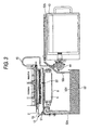
- Fig. 3 is a schematic structural front view of the internal structure of the inkjet printer in which the maintenance unit is in a maintenance position.
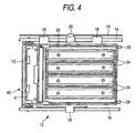
- Fig. 4 is a schematic structural plan view of the maintenance unit.
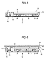
- Fig. 5 is a schematic structural front view of the maintenance unit which has moved to the retraction position.
- Fig. 6 is a schematic structural front view of the maintenance unit which has moved to the maintenance position.
- Figs. 7A and 7B are detailed structural front views of a cap unit.
- Figs. 8A and 8B are explanatory views showing the state where a pressing mechanism is actuated.
- Figs. 9A and 9B are explanatory views showing the state where another pressing mechanism is actuated.
- Figs. 10A to 10D are structural views showing ink reservoirs.
- Figs. 11A to 11C are explanatory views showing modifications as to the state where a primary recovery portion and a secondary recovery portion are in contact with each other.
-
- Next, an embodiment of the invention will be described by way of example.
- Fig. 1 is a schematic structural diagram of the internal structure of an inkjet printer according to an embodiment of the invention, illustrated by way of example and viewed from its left side.
- This inkjet printer 1 is a color inkjet printer, internally provided with four
heads 2 corresponding to inks of four colors (magenta, yellow, cyanandblack), respectively. In addition, the inkjet printer 1 is configured to transport a paper-like recording medium such as recording paper or various film (hereinafter also referred to as "paper") from a paper feed portion 3 on the back side (left in Fig. 1) to a paper discharge portion 4 on the front side (right in Fig. 1) along a paper transport path. The inkjet printer 1 is internally provided with a pair offeed rollers 5, twobelt rollers transport belt 8, a presser member 9, a separation unit 10, aguide member 11, etc. - The pair of
feed rollers 5 are disposed just on the downstream side of the paper feed portion 3, and pulls out paper from the paper feed portion 3 one by one and feeds the paper downstream in the paper transport direction. - The two
belt rollers transport belt 8 laid between thebelt rollers transport belt 8 is driven by one of thebelt rollers 6. Thetransport belt 8 uses its outer circumferential surface as a transport surface to retain thereon the paper fed by the pair offeed rollers 5 and to transport the paper to the downstream side. The outer circumferential surface of thetransport belt 8 has been subjected to silicon treatment so that the paper can be retained on the outer circumferential surface by the adhesive force of the'outer circumferential surface. - The presser member 9 is disposed in a position opposed to the
belt roller 6 through the paper transport path. The presser member 9 presses the paper onto the transport surface of thetransport belt 8 so as to make the paper adhere to the transport surface firmly enough to prevent the paper on thetransport belt 8 from floating from the transport surface. - The separation unit 10 is provided on the downstream side of the
transport belt 8. The separation unit 10 is a unit for separating the paper adhering to the transport surface of thetransport belt 8 from the transport surface, and feeding the paper toward the paper discharge portion 4 on the downstream side. - The
guide member 11 is disposed in a space on the inner circumferential side of thetransport belt 8. Theguide member 11 has a substantially rectangular parallelepiped shape substantially as wide as thetransport belt 8. Theguide member 11 is located to be just opposed to thehead 2. Coming into contact with the inner circumferential surface of thetransport belt 8 passing above theguide member 11, theguide member 11 supports thetransport belt 8 from its inner circumferential side. - The four
heads 2 are disposed in parallel in the paper transport direction. Eachhead 2 is formed into a long rectangular shape extending in a direction perpendicular to the paper transport direction in plan view, and provided with an ink eject portion on its lower end side. The ink eject portion of thehead 2 includes a flow channel unit in which an ink flow channel including a pressure chamber is formed, and an actuator for applying pressure to ink in the pressure chamber. The flow channel unit and the actuator are glued with each other so as to eject ink onto the paper passing under the ink eject portion through small-diameter eject nozzles formed in the bottom surface of the ink eject portion. Eachhead 2 is a line-type head in which a number of eject nozzles required for forming a line of an image extending in a direction perpendicular to the paper transport direction are formed into a predetermined array. Thehead 2 configured thus is disposed to form a slight space between the lower surface of thehead 2 and the transport surface of thetransport belt 8. Thus, the paper transported on thetransport belt 8 passes just under the ink eject portions of the fourheads 2 in turn, and inks of respective colors are ejected from the eject nozzles toward the upper surface (printing surface) of the paper. In such a manner, a desired color image can be formed. - Figs. 2 and 3 are schematic structural front views of the internal structure of the inkjet printer 1. The
heads 2, thebelt roller 6, thetransport belt 8, and so on, described above, are disposed on the left side with respect to the center in Figs. 2 and 3. - Each
head 2 has a structure in which thehead 2 is movable in directions perpendicular to a surface of the paper (up/down directions). Thehead 2 is configured as follows. That is, at the time of printing, thehead 2 driven by a not-shown motor to move to a descent position (see Fig. 2) where thehead 2 approaches the upper surface of thetransport belt 8. At the time of non-printing, thehead 2 driven by the motor to move to an ascent position (see Fig. 3) where thehead 2 has a more distance from the upper surface of thetransport belt 8 than at the time of printing, and expands the hap between thehead 2 and thetransport belt 8. - In addition, a
maintenance unit 12 is disposed in the gap between thehead 2 and thetransport belt 8, which is formed when thehead 2 is displaced to the ascent position. - Fig. 4 is a schematic structural plan view of the
maintenance unit 12. - The
maintenance unit 12 has amovable body 13 movable in the direction (left/right direction), which is perpendicular to the paper transport direction (front/rear direction) and is perpendicular to the moving direction (up/down direction) of thehead 2. - The
movable body 13 is supported slidably on twoguide bars members 18 as shown in Fig. 4. The guide bars 14 and 16 extend horizontally in a direction perpendicular to the paper transport direction. In addition, atiming belt 19 is laid in parallel to the guide bars 14 and 16. Themovable body 13 and thetiming belt 19 are coupled with each other through acoupling member 20. When thetiming belt 19 is actuated by a not-shown motor, themovable body 13 is moved along the guide bars 14 and 16 so that themovable body 13 moves to a first position (see Fig. 3) where themovable body 13 is present in the ink ejection direction with respect to thehead 2, or a second position (see Fig. 2) where themovable body 13 is not present in the ink ejection direction with respect to thehead 2. Incidentally, in the following description, the position of themaintenance unit 12 when themovable body 13 moves to the first position will be referred to as "maintenance position", and the position of themaintenance unit 12 when themovable body 13 moves to the second position will be referred to as "retraction position". - Figs. 5 and 6 are schematic structural front views of the
maintenance unit 12. Fig. 5 shows a state where themaintenance unit 12 has moved to the retraction position. Fig. 6 shows a state where themaintenance unit 12 has moved to the maintenance position. - The
maintenance unit 12 has a structure where acap unit 22 is mounted on the top side of themovable body 13, as shown in Figs. 5 and 6. - The
cap unit 22 is attached to themovable body 13 through a plurality oflinks 24. In particular, thecap unit 22 has a structure as follows. That is, amaintenance holder 26 is provided in a lower portion of thecap unit 22, and one end of eachlink 24 is coupled rotatably with themovable body 13 while the other end of thelink 24 is coupled rotatably with themaintenance holder 26. Due to such a coupling structure, thecap unit 22 canmove obliquelyupward (right obliquely upward in Fig. 5) relatively to themovable body 13 around one end of eachlink 24 in an arc while retaining the parallel position relationship between themaintenance holder 26 and themovable body 13. - When the
maintenance unit 12 is located at the retraction position, thecap unit 22 moves down, due to weight of the ink, to the position where thecap unit 22 comes into contact with the upper surface side of the movable body 13 (see Fig. 5). On the other hand, when themaintenance unit 12 moves to the maintenance position so that eachlever 28 provided to project over themaintenance holder 26 abuts against eachabutment portion 29 on a main body side of the inkjet printer 1, thecap unit 22 moves obliquely upward relatively to themovable body 13 as described above, due to the force of theabutment portion 29 acting on the cap unit 22 (see Fig. 6). Incidentally, thecap unit 22 moves obliquely upward in an arc relatively to themovable body 13 as described above. However, due to the abutment of thelever 28 against theabutment portion 29, thecap unit 22 is not displaced horizontally relatively to theabutment portion 29. Therefore, thecap unit 22 is displaced vertically with respect to the main body of the inkjet printer 1, so as to move upward straightly toward the ink ejection surface of thehead 2 just above thecap unit 22 in Fig. 6 and come into contact with the ink ejection surface. - In this embodiment, a mechanical structure including the
links 24 and thelever 28 is adopted to move thecap unit 22 upward. Since the mechanical structure includes no driving device, e.g. a motor, the mechanical structure has advantages in the size and the cost. - Figs. 7A and 7B are more detailed structural front views of the
cap unit 22. Fig. 7A shows the state where themaintenance unit 12 is located at the retraction position. Fig. 7B shows the state where themaintenance unit 12 is located at the maintenance position. - The
cap unit 22 is provided with a structure including acap holder 30, compression springs 33, acap 34, avalve 35 and so on as well as themaintenance holder 26. - The
cap holder 30 is attached to the upper surface side of themaintenance holder 26 so as to be movable in the up/down direction relatively to themaintenance holder 26. Threeshafts 30a are provided to project from the lower surface side of thecap holder 30. The compression springs 33 are fitted to the outer circumferences of theshafts 30a, respectively. The compression springs 33 are interposed between themaintenance holder 26 and thecap holder 30 so as to apply an urging force to thereby expand the distance between themaintenance holder 26 and thecap holder 30. A plurality of lock pieces (not shown) extending downward are formed on thecap holder 30 . When the distance between themaintenance holder 26 and thecap holder 30 is expanded, those lock pieces are hung on themaintenance holder 26 so as to prevent the distance between themaintenance holder 26 and thecap holder 30 from being expanded to be larger than a predetermined distance. Thus, the compression springs 33 are always compressed somewhat. In addition, twocylindrical portions 30b are provided to project from thecap holder 30. - The
cap 34 is formed out of a material having rubber elasticity, particularly formed out of a material resistant against ink (such as butyl rubber or EPDM). Thecap 34 is mounted on the upper surface side of thecap holder 30 so as to move up/down together with thecap holder 30. The upper end of thecap 34 is formed into a shape, which will surround all of a large number of nozzles formed in the ink ejection surface of thehead 2 when thecap 34 is brought into close contact with the ink ejection surface of thehead 2. Arecess portion 34a dished downward is formed on the upper surface side of thecap 34. Through holes penetrating thecap 34 in the up/down direction are formed at two places, which are the deepest in therecess portion 34a, respectively. The upper ends of thecylindrical portions 30b are inserted into the through holes of thecap 34 respectively. Thus, each of lumens of thecylindrical portions 30b defines each ofink outflow channels 36 for allowing ink to flow out from the inside of thecap 34 to the outside due to weight of the ink. Incidentally, fourcaps 34 are provided correspondingly to the fourheads 2 as shown in Fig. 4. - The
valve 35 includes a plate spring (elastic body) 37 and rubber plates (elastically deformable sealing bodies) 38. Theplate spring 37 is fixed at its longitudinally central portion to the lower surface of themaintenance holder 26 so that the end portions of theplate spring 37 can be deformed elastically. Therubber plates 38 are fixedly attached to the upper surface of theplate spring 37 at its longitudinally opposite end portions respectively. Holes one size larger than therubber plates 38 are formed in themaintenance holder 26. Therubber plates 38 are put into the holes. Thus, therubber plates 38 are positioned to be opposed to the lower ends of thecylindrical portions 30b, respectively. - Incidentally, a
wiping mechanism 40 is also mounted on themaintenance unit 12 as shown in Figs. 5 and 6. Thewiping mechanism 40 is a mechanism for moving awiper blade 41 up and down so as to wipe the ink ejection surface of thehead 2 with thewiper blade 41. When themaintenance unit 12 moves from the retraction position to the maintenance position, thewiper blade 41 is moved upward. When themaintenance unit 12 moves from the maintenance position to the retraction position again, the ink ejection surface of thehead 2 can be wiped with thewiper blade 41. - Further, the inkjet printer 1 has ink supply mechanisms each including an
exchangeable ink cartridge 43, anink supply pump 44 and anink supply tube 45. The ink supply mechanism is configured to supply ink from theink cartridge 43 to thehead 2 through theink supply pump 44 and theink supply tube 45. Four sets of such ink supply mechanisms are provided correspondingly to the number ofheads 2 in order to supply different color inks to the fourheads 2. - The
ink supply pump 44 is actuated to supply ink to thehead 2 for the first time after the exchange of theink cartridge 43. Thus, the ink supply channel from theink cartridge 43 to thehead 2 can be filled with the ink. In addition, theink supply pump 44 is also actuated to perform purge processing for eliminating high-concentration ink staying in the nozzles of thehead 2. Ink is transmitted to thehead 2 under pressure so as to eject the high-concentration ink from the nozzles of thehead 2. Thus, the performance of thehead 2 can be recovered. - In addition, the inkjet printer 1 has a
primary recovery portion 51 and asecondary recovery portion 52 as an ink recovery mechanism. Theprimary recovery portion 51 is mounted on themovable body 13, and thesecondary recovery portion 52 is provided on the main body side of the inkjet printer 1. - The
primary recovery portion 51 is constituted by an ink absorber made from a porous material, nonwoven fabric, or the like, capable of absorbing ink due to a capillary phenomenon. Ink flowing out from thecap 34 flows into theprimary recovery portion 51 through the ink outflow channels 36 (see Figs. 7A and 7B). Thus, the ink is absorbed into theprimary recovery portion 51 temporarily. Theprimary recovery portion 51 has a lower profile than any part of thesecondary recovery portion 52. Thus, the volume of theprimary recovery portion 51 capable of absorbing ink is smaller than that of thesecondary recovery portion 52 in accordance with the size difference. - The
secondary recovery portion 52 includesink absorbers 52a to 52d made of a porous material, nonwoven fabric, or the like, capable of absorbing ink due to a capillary phenomenon in the same manner as theprimary recovery portion 51. Theink absorber 52a is disposed at a position where theprimary recovery portion 51 will come into contact with theink absorber 52a when themaintenance unit 12 moves to the maintenance position (see Fig. 3). Theink absorber 52a can absorb ink from theprimary recovery portion 51 when theprimary recovery portion 51 is in contact with theink absorber 52a. Theink absorber 52b is disposed at a position where theprimary recovery portion 51 will come into contact with theink absorber 52b when themaintenance unit 12 moves to the retraction position (see Fig. 2). Theink absorber 52b can absorb ink from theprimary recovery portion 51 when theprimary recovery portion 51 is in contact with theink absorber 52b. Theink absorber 52c is disposed at a position where theink absorber 52b is always in contact with theink absorber 52c, so that theink absorber 52c can absorb ink from theink absorber 52b. Theink absorber 52d is an ink absorber having the largest volume. Theink absorber 52d is disposed at a position where theink absorbers ink absorber 52d, so that theink absorber 52d can absorb ink from theink absorbers - At a place where the
primary recovery portion 51 and thesecondary recovery portion 52 are in contact with each other or at a place where theink absorbers 52a-52d of the secondary recovery portion 52are in contact with each other, ink migrates in accordance with a difference in volume of absorbed ink, that is, from an ink absorber having a larger volume of absorbed ink to an ink absorber having a smaller volume of absorbed ink. In addition, affected by gravitation, ink is easy to migrate to an ink absorber at a lower position. Thus, when a certain quantity or more of ink has been absorbed, the ink finally migrates to theink absorber 52d, which is disposed at the lowest position. - In the inkjet printer 1 configured thus, at the time of nonprinting (for example, before turning on of power), the
head 2 moves up and themaintenance unit 12 is located at the maintenance position, as shown in Fig. 3. - Here, in order to understand the state where the
maintenance unit 12 is located at the maintenance position, it is important to know the motion of each part of themaintenance unit 12 when themaintenance unit 12 moves from the retraction position to the maintenance position. - When the
maintenance unit 12 moves from the retraction position toward the maintenance position, eachlever 28 abuts against eachabutment portion 29 when themovable body 13 reaches the vicinity of the maintenance position. Then, when themovably body 13 moves further toward the maintenance position while retaining the abutment between thelever 28 and theabutment portion 29, thecap unit 22 moves up toward thehead 2 with the rotations of thelinks 24. Incidentally, thewiping mechanism 40 also operates in this event, so as to move thewiper blade 41 to a position where thewiper blade 41 abuts against the ink ejection surface of thehead 2. - Before the
maintenance unit 12 moves to the maintenance position (that is, when themaintenance unit 12 is located at the retraction position), thecap unit 22 is located at a position where thecap unit 22 has moved down relatively to themovable body 13, and thecap 34 has been separated from the ink ejection surface of thehead 2. Therefore, the pressure force of the compression springs 33 has pushes thecap holder 30 and thecap 34 so as to displace thecap holder 30 and thecap 34 to a position where thecap holder 30 and thecap 34 have moved up relatively to the maintenance holder 26 (see Fig. 7A). In this event, the lower ends of thecylindrical portions 30b on the lower surface side of thecap holder 30 have been separated from the upper surfaces of therubber plates 38 of thevalve 35, so that thevalve 35 has opened theink outflow channels 36. - In this state, when the
maintenance unit 12 moves to the maintenance position and then thecap unit 22 moves up relatively to themovable body 13, thecap holder 30 and thecap 34 move up together with themaintenance holder 26. However, thecap holder 30 and thecap 34 cannot move up any more when the upper end of thecap 34 is brought into abutment and close contact with the ink ejection surface of thehead 2. As a result, only themaintenance holder 26 moves up further relatively to themovable body 13. Thus, the compression springs 33 are compressed between themaintenance holder 26 and thecap holder 30 so that themaintenance holder 26 is displaced to narrow the distance between thecap holder 30 and the maintenance holder 26 (see Fig. 7B). In this event, the lower ends of thecylindrical portions 30b on the lower surface side of thecap holder 30 are pressed onto the upper surfaces of therubber plates 38 of the valve, 35 respectively. Thus, therubber plates 38 are displaced downward to increase bending of theplate spring 37. As a result, therubber plates 38 are brought into pressure contact with the lower ends of thecylindrical portions 30b, respectively by the force of theplate spring 37. Thus, thevalve 35 closes theink outflow channels 36. - Each part on the
maintenance unit 26 operates in such a manner. Thus, at the time of nonprinting when themaintenance unit 12 is located at the maintenance position, thecap 34 is in close contact with thehead 2, and thevalve 35 closes theink outflow channels 36. Accordingly, at the time of nonprinting, the inside of thecap 34 is blocked from the atmosphere so that ink can be prevented from evaporating from the nozzles of thehead 2. - On the other hand, when printing is started, purge processing is first performed to recover the nozzles of the
head 2 from clogging or the like. When the purge processing is performed, theink supply pump 44 is actuated to send ink from theink cartridge 43 to thehead 2 under pressure. Thus, the ink is ejected from the nozzles of thehead 2. The ejected ink stays in thecap 34, but the volume thereof is set to be smaller than the volume of thecap 34. - After that,
themaintenance unit 12 moves to the retraction position as shown in Fig. 2. In this event, themaintenance unit 12 moves toward the retraction position while thewiper blade 41 is wiping the ink ejection surface of thehead 2. In addition, when themaintenance unit 12 moves to the retraction position so that thecap 34 leaves thehead 2, thevalve 35 opens theink outflow channels 36. Thus, the ink staying in thecap 34 flows down through theink outflow channels 36 due to weight of the ink. The ink flowing out theink outflow channels 36 flows down the through holes formed in the bottom portion of themaintenance holder 26 of thecap unit 22. Then, the ink is absorbed into theprimary recovery portion 51 provided on the upper surface side of themovable body 13. - The
primary recovery portion 51 comes into contact with theink absorber 52a of thesecondary recovery portion 52 when themaintenance unit 12 moves to the maintenance position (see Fig. 3). Theprimary recovery portion 51 also comes into contact with theink absorber 52b of thesecondary recovery portion 52 when themaintenance unit 12 moves to the retraction position (see Fig. 2). That is, theprimary recovery portion 51 and thesecondary recovery portion 52 come into contact with each other when themaintenance unit 12 reaches each of the rest positions at the opposite ends. In this state, the ink absorbed in theprimary recovery portion 51 is further absorbed into thesecondary recovery portion 52. Thus, the ink absorbing ability of theprimary recovery portion 51 is restored. Then, the ink absorbed by theink absorbers ink absorber 52d. - Incidentally, after the
maintenance unit 12 moves to the retraction position, thehead 2 moves down. Printing is performed in this state. Further, after the printing is terminated, thehead 2 moves up again while themaintenance unit 12 moves to the maintenance position, as shown in Fig. 3. After becoming this state, the power is turned off. - In the inkjet printer 1 configured thus, the ink in the
cap 34 reaches theprimary recovery portion 51 due to weight of the ink, and further reaches thesecondary recovery portion 52 due to a capillary phenomenon. Accordingly, the ink in thecap 34 can be discharged to the outside of thecap 34 without providing any suction pump. Thus, in the inkjet printer 1, the ink can be discharged to the outside of thecap 34 with no problem in spite of the pressure-system purge processing adopted therein. - In addition, in the inkj et printer 1, the ink once absorbed in the
primary recovery portion 51 including a low-profile ink absorber is moved to the large-volumesecondary recovery portion 52 due to a capillary phenomenon. Accordingly, theprimary recovery portion 51 can be put compactly into a limited space near thecap 34 while the secondary recovery portion is put into an enough space at a distance from thecap 34. Thus, the space inside the printer can be used effectively. - In addition, the inkjet printer 1 has a structure in which the
primary recovery portion 51 moves together with thecap 34. Accordingly, theprimary recovery portion 51 can always absorb ink even during the movement of thecap 34. It is therefore unnecessary to connect thecap 34 and theprimary recovery portion 51 through a long flexible tube. In addition, when themovable body 13 reaches the first or second position, theprimary recovery portion 51 comes into contact with thesecondary recovery portion 52 so that the ink in theprimary recovery portion 51 is made absorbable into thesecondary recovery portion 52. Thus, it is also unnecessary to connect theprimary recovery portion 51 and thesecondary recovery portion 52 through a long flexible tube. Accordingly, even if the structure in which thecap 34 is displaced largely together with themovable body 13 is adopted, it is unnecessary to provide any long flexible tube, and there occurs no problem that such a flexible tube is caught or entangled with anything when the flexible tube moves. Thus, it is also unnecessary to secure a barrier-free space required for wiring such a flexible tube. - The
secondary recovery portion 52 does not require a movable structure in which thesecondary recovery portion 52 is movable following the moving direction of theprimary recovery portion 51. Thus, there occurs no needless trouble such as a failure in operation. Further, the configuration that only theprimary recovery portion 51 moves while theprimary recovery portion 51 is always in contact with thesecondary recovery portion 52 is not adopted. Thus, the abrasion in the contact surface between theprimary recoveryportion 51 and thesecondary recovery portion 52 can be suppressed. - Further, in the inkjet printer 1, the
primary recovery portion 51 is brought into contact with thesecondary recovery portion 52 in each of the rest positions at the opposite ends in the moving direction in which theprimary recovery portion 51 moves forward and backward. Accordingly, ink can be recovered into thesecondary recovery portion 52 efficiently in comparison with a case where such a rest position is set at only one of the opposite ends. - Furthermore, in the inkjet printer 1, an ink absorber capable of absorbing ink due to a capillary phenomenon is provided also in the
primary recovery portion 51. Accordingly, there occurs no trouble that ink spills out due to the vibration of theprimary recovery portion 51 caused by the movement of themovable body 13. - In addition, in the inkjet printer 1, the
valve 35 closes theink outflow channels 36 when thecap 34 is in close contact with thehead 2. Accordingly, there is no fear that the atmosphere is introduced into thecap 34 through theink outflow channels 36. Thus, the effect of retaining the moist condition of thehead 2 is enhanced so that the ink in the nozzles can be prevented from increasing in concentration. - Also, in the ink jet printer 1, the
valve 35 of the simple configuration can open and close theink outflow channels 36. Therefore, thevalve 35 can switch easily between the open state in which ink is flown out from thecap 34 and the close state in which theink outflow channels 36 are sealed adequately. - Incidentally, in the case where such a
valve 35 is provided, when thecap 34 is brought into close contact with thehead 2 for performing purge processing, thevalve 35 closes theink outflow channel 36 so that the ink stays in thecap 34 or theink outflow channel 36. Routinely, it is therefore preferable to separate thecap 34 from thehead 2 to thereby open thevalve 35 at least once, and then close thevalve 35 after the ink flows out through theink outflow channel 36. For example, when printing operation is performed at least once after the purge processing, thecap 34 can be separated from thehead 2 to thereby open thevalve 35. Thus, it is sufficient to perform the printing operation. - However, differently from a long flexible tube needing a pump, the
ink outflow channel 36 is formed to allow ink to flow down due to weight of the ink, so that there is no fear that theink outflow channel 36 is clogged with the ink even if the concentration of the ink increases somewhat. Accordingly, there is no special problem even if a small quantity of ink is left in thecap 34 or theink outflow channel 36 when thevalve 35 is closed. Thus, there is no problem even if thevalve 35 is left closed with ink staying due to power off or the like. - It can be expected, if anything, that a small quantity of ink staying may enhance the effect of keeping the head moist. Accordingly, to enhance the effect of keeping the head moist, the
valve 35 may be closed in the state in which a certain quantity of ink stays in theink outflow channel 36, or a small quantity of ink may be ejected from thehead 2 after thevalve 35 is closed. In such a manner, a small quantity of ink may be left in thecap 34 or theink outflow channel 36 on purpose. - Although the embodiment of the invention has been described above, the invention is not limited to the specific embodiment, but the invention can be carried out in various modes other than the embodiment. Description will be made below on useful modifications.
- In the aforementioned embodiment, the ink absorber of the
primary recovery portion 51 and theink absorber secondary recovery portion 52 are disposed so that the both are brought into pressure contact with each other simply by the displacement of themovable body 13 to the first or second position. However, there may be provided a pressing mechanism for displacing a part of thesecondary recovery portion 52 interlocking with the motion of theprimary recovery portion 51 to press thesecondary recovery portion 52 onto theprimary recovery portion 51 when theprimary recovery portion 51 reaches the rest position. - More detailed description will be given below. For example, a
pressing mechanism 54 as shown in Figs. 8A and 8B may be adopted in the inkjet printer 1. - The
pressing mechanism 54 is a mechanism for pressing anink absorber 52e, which is a part of thesecondary recovery portion 52, onto theprimary recovery portion 51 when themaintenance unit 12 moves to the maintenance position. Thepressing mechanism 54 has arotary member 60 and atorsion spring 62. Therotary member 60 can rotate around aspindle 58 fixed to aframe 56. Thetorsion spring 62 urges therotary member 60 to rotate clockwise in Figs. 8A and 8B. - Till the
maintenance unit 12 reaches the maintenance position, thetorsion spring 62 urges therotary member 60 to thereby displace therotary member 60 to the position shown in Fig. 8A. When themaintenance unit 12 approaches the maintenance position, a side surface of themaintenance unit 12 comes into contact with alever 60a of therotary member 60. Under such a condition, themaintenance unit 12 reaches the maintenance position while pushing thelever 60a. In this event, therotary member 60 including thelever 60a pushed rotates counterclockwise in Figs. 8A and 8B, so as to be displaced to the position shown in Fig. 8B. In accordance with the displacement, theink absorber 52e retained by therotary member 60 is displaced upward and pressed onto theprimary recovery portion 51. Incidentally, therotary member 60 also retains theink absorber 52a. The ink absorbed in theink absorber 52e is absorbed further into theink absorber 52a. Thus, the ink is recovered into thesecondary recovery portion 52. - In addition, for example, a
pressing mechanism 64 as shown in Figs. 9A and 9B may be adopted in the inkjet printer 1. - The
pressing mechanism 64 is a mechanism for pressing anink absorber 52f, which is a part of thesecondary recovery portion 52, onto theprimary recovery portion 51 when themaintenance unit 12 moves to the retraction position. Thepressing mechanism 64 includes arotary member 70 which can rotate around aspindle 68 fixed to aframe 66. - Till the
maintenance unit 12 reaches the retraction position, therotary member 70 rotates due to weight of the ink based on a relationship between aspindle 68 as the center of rotation and the center of gravity, so as to be displaced to the position shown in Fig. 9A. When themaintenance unit 12 approaches the retraction position, apin 72 provided to proj ect on a side surface of themaintenance unit 12 abuts against alever 70a of therotary member 70. Under such a condition, themaintenance unit 12 reaches the retraction position while pushing up thelever 70a. In this event, therotary member 70 including thelever 70a pushed up rotates clockwise in Figs. 9A and 9B, so as to be displaced to the position shown in Fig. 9B. In accordance with the displacement, theink absorber 52f retained by therotary member 70 is displaced upward and pressed onto theprimary recovery portion 51. Incidentally, theink absorbers secondary recovery portion 52 are also retained on theframe 66 so as to slide-contact with theink absorber 52f. Therefore, the ink absorbed in theink absorber 52f is absorbed further into theink absorbers secondary recovery portion 52. - When the
pressing mechanism secondary recovery portion 52 is displaced interlocking with the motion of theprimary recovery portion 51 so that thesecondary recovery portion 52 is pressed onto theprimary recovery portion 51. Thus, the close contact performance between theprimary recovery portion 51 and thesecondary recovery portion 52 is enhanced so that ink can be recovered into thesecondary recovery portion 52 efficiently. - Incidentally, not to say, it is preferable to provide both the
pressing mechanisms - In terms of enhancement in the close contact performance between the
primary recovery portion 51 and thesecondary recovery portion 52, it is preferable to provide thepressing mechanism pressing mechanisms pressing mechanism pressing mechanism - When the
secondary recovery portion 52 has a single ink absorber, a part of the single ink absorber corresponds to the part of thesecondary recovery portion 52 to be displaced by thepressing mechanism secondary recovery portion 52 has a plurality of ink absorbers adapted so that ink absorbed by one of the ink absorbers is absorbed by another ink absorber in turn, a part or all of one of the ink absorbers corresponds to the part of thesecondary recovery portion 52 to be displaced by thepressing mechanism - Next, the embodiment has shown the case where the
ink outflow channels 36 are closed by thevalve 35 when thecap 34 is in close contact with thehead 2. However, the atmosphere may be prevented from flowing back into theink outflow channels 36 by use of another means. - More detailed description will be given below. An
ink reservoir - The
ink reservoir 74 is provided in place of therubber plate 38 of thevalve 35. Theink reservoir 76 is formed as a recess portion deeper than theink reservoir 74, by perforating theplate spring 37. - With the movement of the
maintenance holder 26, the lower end of eachcylindrical portion 30b formed in thecap holder 30 is made to separate from the ink in theink reservoir 74, 76 (see Fig. 10A, 10C) or to sink in the ink in theink reservoir 74, 76 (see Fig. 10B, 10D). When the lower end of thecylindrical portion 30b has sunk in the ink, the air flow is blocked by the ink. Therefore, the air-tightness is retained without bringing theink reservoir 74 into strong pressure contact with the lower end of thecylindrical portion 30b. Thus, the atmosphere can be prevented from flowing back into theink outflow channel 36. - Incidentally, as shown in Fig. 10D, the lower end of the
cylindrical portion 30b may always sink in the ink so long as it is not in contact with the bottom of theink reservoir 76. That is, if ink flows into thecylindrical portion 30b from above, a part of the ink will stay in theink reservoir 76 while the rest overflows downstream from theink reservoir 76. Thus, since the air flowing back through theink outflow channel 36 can be blocked by the ink staying in theink reservoir 76, it is not always necessary to displace thecylindrical portion 30b to the position shown in Fig. 10C. Such a structure has a function just the same as a drain trap to be provided in a drain pipe. In other words, an ink reservoir formed to have a structure similar to a known drain trap canblock the atmosphere flowing back through theink outflow channel 36 while allowing ink to flow out therethrough. - In Figs. 10C and 10D, the
ink reservoir 76 is provided on theplate spring 37 expediently in order to clarify the relationship to the aforementioned embodiment. However, in the structure where the lower end of thecylindrical portion 30b is not in contact with the bottom of theink reservoir 76, thecylindrical portion 30b applies no pressing force to theplate spring 37. Thus, theink reservoir 76 may be provided not on theplate spring 37 but on a member whose rigidity is too high to be elastically deformed. - In addition, the air-tightness is always retained due to the
ink reservoir cap 34 through theink outflow channel 36. Thus, the effect of keeping thehead 2 moist is enhanced so that the ink in the nozzles can be prevented from increasing in concentration. - As for the specific shape of the
ink reservoir ink reservoir ink outflow channel 36 while allowing ink to flow out therethrough. - Incidentally, both the
ink reservoir valve 35 are countermeasures for preventing the atmosphere frombeing introduced into thecap 34 through theink outflow channel 36. Therefore, one of those countermeasures may be adopted to make the structure simpler. However, structurally, it is possible to adopt both theink reservoir valve 35. Therefore, both the means may be adopted to attach importance to the effect of keeping thehead 2 moist. - The aforementioned embodiment shows a case where the
primary recoveryportion 51 comes into contact with thesecondary recovery portion 52 so as to allow thesecondary recovery portion 52 to absorb ink from theprimary recovery portion 51 when theprimary recovery portion 51 reaches a rest position where it stops moving. The invention is not limited to this embodiment, but may be applied to, for example, a structure where theprimary recovery portion 51 is in contact with theprimary recovery portion 52 even during the movement of theprimary recovery portion 51. In this case, however, the sliding surface between theprimary recovery portion 51 and thesecondary recovery portion 52 is abraded easily. Thus, it is desired to adopt a structure in which such abrasion can be suppressed. - An example of such a structure capable of suppressing abrasion may include a structure in which
rollers 51a made of hard felt are provided as parts of theprimary recovery portion 51, for example, as shown in Fig. 11B. When such a structure is adopted, ink is absorbed into thesecondary recovery portion 52 through therollers 51a while the abrasion occurring between theprimary recovery portion 51 and thesecondary recovery portion 52 is suppressed because therollers 51a roll on thesecondary recovery portion 52 during the movement of theprimary recovery portion 51. - Alternatively,
rollers 51b made of resin and having a large number of grooves cut in its circumference may be provided in stead of therollers 51a made of hard felt. Therollers 51b receive ink from theprimary recovery portion 51 into the grooves or scrape ink from theprimary recovery portion 51 through the grooves, and migrate the ink retained in the grooves to thesecondary recovery portion 52. Even when such a structure is adopted, ink is absorbed into thesecondary recovery portion 52 through therollers 51b while the abrasion occurring between theprimary recovery portion 51 and thesecondary recovery portion 52 is suppressed because therollers 51b roll on thesecondary recovery portion 52 during the movement of theprimary recovery portion 51. - Although the
primary recovery portion 51 including an ink absorber is provided on themovable body 13 in the aforementioned embodiment, the primary recovery portion may be arranged without using any ink absorber. For example, an ink reservoir similar to that shown in Fig. 10A-10D may be provided under thecap unit 22. In this case, thesecondary recovery portion 52 is adapted to enter the ink reservoir whenever themaintenance unit 12 is disposed in any one of the maintenance position and the retraction position. - Further, although the inkjet printer 1 illustrated in the aforementioned embodiment is a line printer having line-
type heads 2, the configuration according to the invention is also applicable to a serial printer performing printing while moving heads forward/backward in a direction perpendicular to the paper transport direction.
Claims (12)
- An inkjet printer comprising:a head including an ink ejection surface that ejects ink;a cap capable of moving to come into contact with the ink ej ection surface of the head, the cap includes an ink outflow channel where the ink ejected from the head flows out to external due to weight of the ink;a primary recovery portion that allows the ink flowing out from the cap through the ink outflow channel to flow into the primary recovery portion to recover the ink; anda secondary recovery portion including an ink absorber, which absorbs the ink due to a capillary phenomenon from the primary recovery portion to recover the ink.
- The inkjet printer according to claim 1, wherein:the primary recovery portion moves together with the cap; andthe primary recovery portion comes into contact with the secondary recovery portion and allows the secondary recovery portion to absorb the ink from the primary recovery portion when the primary recovery portion reaches a rest position where the primary recovery portion stops moving.
- The inkjet printer according to claim 2, wherein:the primary recovery portion moves forward and backward between two positions;the rest position is located in each of both ends in a moving direction of the primary recovery portion; andthe primary recovery portion comes into contact with the secondary recovery portion when the primary recovery portion reaches the rest position in each of both ends.
- The inkjet printer according to claim 2 or 3, further comprising:a pressing mechanism that displaces a part of the secondary recovery portion interlocking with the motion of the primary recovery portion to press the secondary recovery portion onto the primary recovery portion when the primary recovery portion reaches the rest position.
- The inkjet printer according to any preceding claim, wherein the primary recovery portion includes an ink absorber that absorbs the ink due to the capillary phenomenon.
- The inkjet printer according to any preceding claim, further comprising:a valve that closes the ink outflow channel when the cap is in close contact with the head and opens the ink outflow channel when the cap is at a distance from the head.
- The inkjet printer according to any preceding claim, further comprising:an ink reservoir disposed in the middle of the ink outflow channel, the ink reservoir that reserves apart of the ink flowing into the ink reservoir from an upstream and allows the rest of the ink to overflow to a downstream, to make the reserved ink block gas flowing back through the ink outflow channel.
- The inkjet printer according to any preceding claim, further comprising:an ink reservoir disposed at an outlet of the ink outflow channel, the ink reservoir that reserves apart of the ink flowing into the ink reservoir from an upstream and allows the rest of the ink to overflow to a downstream, to make the reserved ink block gas flowing back through the ink outflow channel.
- The ink jet printer according to any preceding claim, wherein:the cap moves between a first position and a second position;when the cap reaches the first position, the cap is in close contact with the head.
- An inkjet printer according to any preceding claim wherein the head is a line-type head fixed to a main body at a position where the head faces a transport path of a paper-like recording medium, the inkjet printer further comprising:whereina movable body movable forward and backward between a first position where the movable body is present in front of the ink ejection surface of the head in an ink ejection direction and a second position where the movable body is out of a front of the ink ejection surface of the head in the ink ejection direction;
the cap is mounted on the movable body;
the primary recovery portion is mounted on the movable body;
the secondary recovery portion is fixed to the main body; and
the primary recovery portion comes into contact with the secondary recovery portion to allow the secondary recovery portion to absorb the ink from the primary recovery portion when the movable body reaches one of the first and second positions. - A cap unit for a maintenance unit of an ink jet printer, the cap unit comprising:a cap member including a channel communicating one side of the cap member and another side of the cap member; anda valve that contacts an end portion of the channel to close the channel.
- The cap unit according to claim 11, further comprising:an urging member that urges the valve when the valve closes the channel.
Applications Claiming Priority (2)
| Application Number | Priority Date | Filing Date | Title |
|---|---|---|---|
| JP2003092245A JP3960246B2 (en) | 2003-03-28 | 2003-03-28 | Inkjet printer |
| JP2003092245 | 2003-03-28 |
Publications (3)
| Publication Number | Publication Date |
|---|---|
| EP1462259A2 true EP1462259A2 (en) | 2004-09-29 |
| EP1462259A3 EP1462259A3 (en) | 2005-12-21 |
| EP1462259B1 EP1462259B1 (en) | 2008-01-02 |
Family
ID=32821630
Family Applications (1)
| Application Number | Title | Priority Date | Filing Date |
|---|---|---|---|
| EP04251759A Expired - Lifetime EP1462259B1 (en) | 2003-03-28 | 2004-03-26 | Inkjet printer and cap unit for maintenance unit of inkjet printer |
Country Status (5)
| Country | Link |
|---|---|
| US (1) | US7399055B2 (en) |
| EP (1) | EP1462259B1 (en) |
| JP (1) | JP3960246B2 (en) |
| CN (2) | CN100352655C (en) |
| DE (1) | DE602004010944T2 (en) |
Cited By (1)
| Publication number | Priority date | Publication date | Assignee | Title |
|---|---|---|---|---|
| CN102079169A (en) * | 2009-11-27 | 2011-06-01 | 兄弟工业株式会社 | Capping device and liquid ejection apparatus |
Families Citing this family (9)
| Publication number | Priority date | Publication date | Assignee | Title |
|---|---|---|---|---|
| JP4479649B2 (en) | 2005-11-24 | 2010-06-09 | ブラザー工業株式会社 | Inkjet recording device |
| KR20080104509A (en) * | 2007-05-28 | 2008-12-03 | 삼성전자주식회사 | Inkjet head cleaning apparatus and inkjet image forming apparatus having the same |
| JP5765005B2 (en) * | 2011-03-29 | 2015-08-19 | セイコーエプソン株式会社 | inkjet printer |
| US8702186B2 (en) | 2012-01-26 | 2014-04-22 | Xerox Corporation | Method and apparatus for ink recirculation |
| US8714721B2 (en) | 2012-04-02 | 2014-05-06 | Xerox Corporation | Compliant liquid path member and receptacle for ink recirculation |
| US10828901B1 (en) | 2019-05-20 | 2020-11-10 | Xerox Corporation | Printhead cap for attenuating the drying of ink from a printhead during periods of printer inactivity |
| US10814634B1 (en) | 2019-07-11 | 2020-10-27 | Xerox Corporation | Printhead cap for attenuating the drying of ink from a printhead during periods of printer inactivity |
| CN118769723B (en) * | 2024-07-12 | 2025-09-09 | 贵州劲嘉新型包装材料有限公司 | Digital jet printing equipment with spray head protection and cleaning device |
| CN119116554B (en) * | 2024-11-14 | 2025-03-07 | 杭州晶迈达数码科技有限公司 | Banding strip printing device |
Citations (2)
| Publication number | Priority date | Publication date | Assignee | Title |
|---|---|---|---|---|
| JP2001301186A (en) | 2000-04-24 | 2001-10-30 | Casio Comput Co Ltd | Capping equipment |
| JP2002301831A (en) | 2001-04-05 | 2002-10-15 | Seiko Epson Corp | Ink jet recording device |
Family Cites Families (13)
| Publication number | Priority date | Publication date | Assignee | Title |
|---|---|---|---|---|
| US4383263A (en) * | 1980-05-20 | 1983-05-10 | Canon Kabushiki Kaisha | Liquid ejecting apparatus having a suction mechanism |
| JPS61121950A (en) * | 1984-11-19 | 1986-06-09 | Canon Inc | Suction recovery apparatus of ink jet printer |
| JP2714056B2 (en) * | 1988-10-19 | 1998-02-16 | キヤノン株式会社 | Ink jet recording apparatus capable of detachably attaching waste ink container and waste ink container used therein |
| JP2688258B2 (en) | 1989-09-22 | 1997-12-08 | キヤノン株式会社 | Ink jet recording device |
| DE69109894T2 (en) * | 1990-02-02 | 1995-11-30 | Canon Kk | Ink jet recorder. |
| JPH0924618A (en) * | 1995-07-10 | 1997-01-28 | Canon Inc | Ink jet recording device |
| JPH1044471A (en) * | 1996-08-07 | 1998-02-17 | Matsushita Electric Ind Co Ltd | Ink jet recording device |
| JP2000127439A (en) * | 1998-10-27 | 2000-05-09 | Canon Inc | Waste ink tank and inkjet recording device |
| JP4451513B2 (en) * | 1999-07-23 | 2010-04-14 | キヤノンファインテック株式会社 | Inkjet recording device |
| JP2001071521A (en) * | 1999-09-08 | 2001-03-21 | Casio Comput Co Ltd | Inkjet printer |
| JP3994636B2 (en) | 2000-06-09 | 2007-10-24 | セイコーエプソン株式会社 | Inkjet recording device |
| JP2002200777A (en) * | 2000-12-28 | 2002-07-16 | Fuji Xerox Co Ltd | Ink suction device, ink jet recording head recovery device, ink jet recording device, and ink suction method |
| JP2002355982A (en) | 2001-05-31 | 2002-12-10 | Olympus Optical Co Ltd | Recovery device for inkjet printer |
-
2003
- 2003-03-28 JP JP2003092245A patent/JP3960246B2/en not_active Expired - Fee Related
-
2004
- 2004-03-26 EP EP04251759A patent/EP1462259B1/en not_active Expired - Lifetime
- 2004-03-26 US US10/809,365 patent/US7399055B2/en not_active Expired - Fee Related
- 2004-03-26 DE DE602004010944T patent/DE602004010944T2/en not_active Expired - Lifetime
- 2004-03-29 CN CNB2004100314185A patent/CN100352655C/en not_active Expired - Fee Related
- 2004-03-29 CN CNU2004200064503U patent/CN2841342Y/en not_active Expired - Fee Related
Patent Citations (2)
| Publication number | Priority date | Publication date | Assignee | Title |
|---|---|---|---|---|
| JP2001301186A (en) | 2000-04-24 | 2001-10-30 | Casio Comput Co Ltd | Capping equipment |
| JP2002301831A (en) | 2001-04-05 | 2002-10-15 | Seiko Epson Corp | Ink jet recording device |
Cited By (4)
| Publication number | Priority date | Publication date | Assignee | Title |
|---|---|---|---|---|
| CN102079169A (en) * | 2009-11-27 | 2011-06-01 | 兄弟工业株式会社 | Capping device and liquid ejection apparatus |
| EP2327552A3 (en) * | 2009-11-27 | 2012-05-02 | Brother Kogyo Kabushiki Kaisha | Capping device and liquid ejection apparatus |
| CN102079169B (en) * | 2009-11-27 | 2013-10-02 | 兄弟工业株式会社 | Capping device and liquid ejection apparatus |
| US8708455B2 (en) | 2009-11-27 | 2014-04-29 | Brother Kogyo Kabushiki Kaisha | Capping device and liquid ejection apparatus |
Also Published As
| Publication number | Publication date |
|---|---|
| CN2841342Y (en) | 2006-11-29 |
| US20040189739A1 (en) | 2004-09-30 |
| CN100352655C (en) | 2007-12-05 |
| JP2004299105A (en) | 2004-10-28 |
| CN1569469A (en) | 2005-01-26 |
| JP3960246B2 (en) | 2007-08-15 |
| EP1462259B1 (en) | 2008-01-02 |
| EP1462259A3 (en) | 2005-12-21 |
| DE602004010944T2 (en) | 2009-01-02 |
| DE602004010944D1 (en) | 2008-02-14 |
| US7399055B2 (en) | 2008-07-15 |
Similar Documents
| Publication | Publication Date | Title |
|---|---|---|
| US7722156B2 (en) | Ink supply system with separate purging reservoir | |
| JP4880564B2 (en) | Liquid container and image forming apparatus | |
| US7404615B2 (en) | Maintenance and recovery device of a liquid discharge apparatus and an image forming apparatus | |
| US20130038662A1 (en) | Printhead maintenance assembly having first and second transfer rollers | |
| EP1462259B1 (en) | Inkjet printer and cap unit for maintenance unit of inkjet printer | |
| JP5073596B2 (en) | Image forming apparatus | |
| US8562103B2 (en) | Recovery apparatus and image forming apparatus | |
| JP5381296B2 (en) | Ink cartridge and image forming apparatus | |
| JP2002337351A (en) | INK JET RECORDING APPARATUS, METHOD OF CONTROLLING MOVING POSITION OF CAPping MEANS IN THE APPARATUS, AND FLUSHING CONTROL METHOD IN THE APPARATUS | |
| JP2001293874A (en) | Ink jet printer and head cartridge thereof | |
| US20060250437A1 (en) | Method of removing flooded ink from a printhead using a disposable sheet | |
| US20070080981A1 (en) | Printhead maintenance system comprising face flooding system and ink transport assembly | |
| JP2010042661A (en) | Liquid jet apparatus | |
| JP4006914B2 (en) | Inkjet recording device | |
| JP2012106429A (en) | Liquid jet apparatus | |
| JPH0924625A (en) | Ink jet recording device | |
| JP2012106430A (en) | Liquid jet apparatus | |
| JP2001301185A (en) | Ink jet recording device | |
| JP2002292886A (en) | Ink jet recording device | |
| JP3856963B2 (en) | Inkjet recording device | |
| JP2010111065A (en) | Capping device | |
| JP2002113883A (en) | Ink jet recording device |
Legal Events
| Date | Code | Title | Description |
|---|---|---|---|
| PUAI | Public reference made under article 153(3) epc to a published international application that has entered the european phase |
Free format text: ORIGINAL CODE: 0009012 |
|
| AK | Designated contracting states |
Kind code of ref document: A2 Designated state(s): AT BE BG CH CY CZ DE DK EE ES FI FR GB GR HU IE IT LI LU MC NL PL PT RO SE SI SK TR |
|
| AX | Request for extension of the european patent |
Extension state: AL HR LT LV MK |
|
| PUAL | Search report despatched |
Free format text: ORIGINAL CODE: 0009013 |
|
| AK | Designated contracting states |
Kind code of ref document: A3 Designated state(s): AT BE BG CH CY CZ DE DK EE ES FI FR GB GR HU IE IT LI LU MC NL PL PT RO SE SI SK TR |
|
| AX | Request for extension of the european patent |
Extension state: AL LT LV MK |
|
| 17P | Request for examination filed |
Effective date: 20060504 |
|
| AKX | Designation fees paid |
Designated state(s): DE FR GB |
|
| 17Q | First examination report despatched |
Effective date: 20060816 |
|
| GRAP | Despatch of communication of intention to grant a patent |
Free format text: ORIGINAL CODE: EPIDOSNIGR1 |
|
| GRAS | Grant fee paid |
Free format text: ORIGINAL CODE: EPIDOSNIGR3 |
|
| GRAA | (expected) grant |
Free format text: ORIGINAL CODE: 0009210 |
|
| AK | Designated contracting states |
Kind code of ref document: B1 Designated state(s): DE FR GB |
|
| REG | Reference to a national code |
Ref country code: GB Ref legal event code: FG4D |
|
| REF | Corresponds to: |
Ref document number: 602004010944 Country of ref document: DE Date of ref document: 20080214 Kind code of ref document: P |
|
| ET | Fr: translation filed | ||
| PLBE | No opposition filed within time limit |
Free format text: ORIGINAL CODE: 0009261 |
|
| STAA | Information on the status of an ep patent application or granted ep patent |
Free format text: STATUS: NO OPPOSITION FILED WITHIN TIME LIMIT |
|
| 26N | No opposition filed |
Effective date: 20081003 |
|
| REG | Reference to a national code |
Ref country code: FR Ref legal event code: PLFP Year of fee payment: 13 |
|
| REG | Reference to a national code |
Ref country code: FR Ref legal event code: PLFP Year of fee payment: 14 |
|
| REG | Reference to a national code |
Ref country code: FR Ref legal event code: PLFP Year of fee payment: 15 |
|
| PGFP | Annual fee paid to national office [announced via postgrant information from national office to epo] |
Ref country code: DE Payment date: 20190312 Year of fee payment: 16 Ref country code: GB Payment date: 20190320 Year of fee payment: 16 |
|
| PGFP | Annual fee paid to national office [announced via postgrant information from national office to epo] |
Ref country code: FR Payment date: 20190213 Year of fee payment: 16 |
|
| REG | Reference to a national code |
Ref country code: DE Ref legal event code: R119 Ref document number: 602004010944 Country of ref document: DE |
|
| PG25 | Lapsed in a contracting state [announced via postgrant information from national office to epo] |
Ref country code: DE Free format text: LAPSE BECAUSE OF NON-PAYMENT OF DUE FEES Effective date: 20201001 Ref country code: FR Free format text: LAPSE BECAUSE OF NON-PAYMENT OF DUE FEES Effective date: 20200331 |
|
| GBPC | Gb: european patent ceased through non-payment of renewal fee |
Effective date: 20200326 |
|
| PG25 | Lapsed in a contracting state [announced via postgrant information from national office to epo] |
Ref country code: GB Free format text: LAPSE BECAUSE OF NON-PAYMENT OF DUE FEES Effective date: 20200326 |