EP1462197A1 - Drill and throwaway tip - Google Patents
Drill and throwaway tip Download PDFInfo
- Publication number
- EP1462197A1 EP1462197A1 EP02788715A EP02788715A EP1462197A1 EP 1462197 A1 EP1462197 A1 EP 1462197A1 EP 02788715 A EP02788715 A EP 02788715A EP 02788715 A EP02788715 A EP 02788715A EP 1462197 A1 EP1462197 A1 EP 1462197A1
- Authority
- EP
- European Patent Office
- Prior art keywords
- insert
- main body
- concave groove
- drill main
- drill
- Prior art date
- Legal status (The legal status is an assumption and is not a legal conclusion. Google has not performed a legal analysis and makes no representation as to the accuracy of the status listed.)
- Granted
Links
- 238000003780 insertion Methods 0.000 claims description 28
- 230000037431 insertion Effects 0.000 claims description 28
- 239000012530 fluid Substances 0.000 claims description 10
- 230000003247 decreasing effect Effects 0.000 claims description 7
- 238000003754 machining Methods 0.000 abstract description 43
- 238000010586 diagram Methods 0.000 description 10
- 238000005553 drilling Methods 0.000 description 5
- 238000005520 cutting process Methods 0.000 description 4
- 238000004519 manufacturing process Methods 0.000 description 4
- 238000000034 method Methods 0.000 description 3
- 230000015572 biosynthetic process Effects 0.000 description 1
- 230000015556 catabolic process Effects 0.000 description 1
- 238000006731 degradation reaction Methods 0.000 description 1
- 238000005516 engineering process Methods 0.000 description 1
- 239000000463 material Substances 0.000 description 1
- 230000002093 peripheral effect Effects 0.000 description 1
Images



Classifications
-
- B—PERFORMING OPERATIONS; TRANSPORTING
- B23—MACHINE TOOLS; METAL-WORKING NOT OTHERWISE PROVIDED FOR
- B23B—TURNING; BORING
- B23B51/00—Tools for drilling machines
- B23B51/06—Drills with lubricating or cooling equipment
-
- B—PERFORMING OPERATIONS; TRANSPORTING
- B23—MACHINE TOOLS; METAL-WORKING NOT OTHERWISE PROVIDED FOR
- B23B—TURNING; BORING
- B23B51/00—Tools for drilling machines
- B23B51/02—Twist drills
-
- B—PERFORMING OPERATIONS; TRANSPORTING
- B23—MACHINE TOOLS; METAL-WORKING NOT OTHERWISE PROVIDED FOR
- B23B—TURNING; BORING
- B23B51/00—Tools for drilling machines
-
- B—PERFORMING OPERATIONS; TRANSPORTING
- B23—MACHINE TOOLS; METAL-WORKING NOT OTHERWISE PROVIDED FOR
- B23B—TURNING; BORING
- B23B2200/00—Details of cutting inserts
- B23B2200/16—Supporting or bottom surfaces
- B23B2200/167—Supporting or bottom surfaces with serrations
-
- B—PERFORMING OPERATIONS; TRANSPORTING
- B23—MACHINE TOOLS; METAL-WORKING NOT OTHERWISE PROVIDED FOR
- B23B—TURNING; BORING
- B23B2205/00—Fixation of cutting inserts in holders
- B23B2205/12—Seats for cutting inserts
-
- B—PERFORMING OPERATIONS; TRANSPORTING
- B23—MACHINE TOOLS; METAL-WORKING NOT OTHERWISE PROVIDED FOR
- B23B—TURNING; BORING
- B23B2251/00—Details of tools for drilling machines
- B23B2251/02—Connections between shanks and removable cutting heads
-
- B—PERFORMING OPERATIONS; TRANSPORTING
- B23—MACHINE TOOLS; METAL-WORKING NOT OTHERWISE PROVIDED FOR
- B23B—TURNING; BORING
- B23B2251/00—Details of tools for drilling machines
- B23B2251/50—Drilling tools comprising cutting inserts
-
- B—PERFORMING OPERATIONS; TRANSPORTING
- B23—MACHINE TOOLS; METAL-WORKING NOT OTHERWISE PROVIDED FOR
- B23B—TURNING; BORING
- B23B2260/00—Details of constructional elements
- B23B2260/132—Serrations
-
- Y—GENERAL TAGGING OF NEW TECHNOLOGICAL DEVELOPMENTS; GENERAL TAGGING OF CROSS-SECTIONAL TECHNOLOGIES SPANNING OVER SEVERAL SECTIONS OF THE IPC; TECHNICAL SUBJECTS COVERED BY FORMER USPC CROSS-REFERENCE ART COLLECTIONS [XRACs] AND DIGESTS
- Y10—TECHNICAL SUBJECTS COVERED BY FORMER USPC
- Y10S—TECHNICAL SUBJECTS COVERED BY FORMER USPC CROSS-REFERENCE ART COLLECTIONS [XRACs] AND DIGESTS
- Y10S408/00—Cutting by use of rotating axially moving tool
- Y10S408/713—Tool having detachable cutting edge
-
- Y—GENERAL TAGGING OF NEW TECHNOLOGICAL DEVELOPMENTS; GENERAL TAGGING OF CROSS-SECTIONAL TECHNOLOGIES SPANNING OVER SEVERAL SECTIONS OF THE IPC; TECHNICAL SUBJECTS COVERED BY FORMER USPC CROSS-REFERENCE ART COLLECTIONS [XRACs] AND DIGESTS
- Y10—TECHNICAL SUBJECTS COVERED BY FORMER USPC
- Y10T—TECHNICAL SUBJECTS COVERED BY FORMER US CLASSIFICATION
- Y10T408/00—Cutting by use of rotating axially moving tool
- Y10T408/44—Cutting by use of rotating axially moving tool with means to apply transient, fluent medium to work or product
- Y10T408/45—Cutting by use of rotating axially moving tool with means to apply transient, fluent medium to work or product including Tool with duct
- Y10T408/455—Conducting channel extending to end of Tool
-
- Y—GENERAL TAGGING OF NEW TECHNOLOGICAL DEVELOPMENTS; GENERAL TAGGING OF CROSS-SECTIONAL TECHNOLOGIES SPANNING OVER SEVERAL SECTIONS OF THE IPC; TECHNICAL SUBJECTS COVERED BY FORMER USPC CROSS-REFERENCE ART COLLECTIONS [XRACs] AND DIGESTS
- Y10—TECHNICAL SUBJECTS COVERED BY FORMER USPC
- Y10T—TECHNICAL SUBJECTS COVERED BY FORMER US CLASSIFICATION
- Y10T408/00—Cutting by use of rotating axially moving tool
- Y10T408/89—Tool or Tool with support
- Y10T408/909—Having peripherally spaced cutting edges
- Y10T408/9098—Having peripherally spaced cutting edges with means to retain Tool to support
-
- Y—GENERAL TAGGING OF NEW TECHNOLOGICAL DEVELOPMENTS; GENERAL TAGGING OF CROSS-SECTIONAL TECHNOLOGIES SPANNING OVER SEVERAL SECTIONS OF THE IPC; TECHNICAL SUBJECTS COVERED BY FORMER USPC CROSS-REFERENCE ART COLLECTIONS [XRACs] AND DIGESTS
- Y10—TECHNICAL SUBJECTS COVERED BY FORMER USPC
- Y10T—TECHNICAL SUBJECTS COVERED BY FORMER US CLASSIFICATION
- Y10T408/00—Cutting by use of rotating axially moving tool
- Y10T408/89—Tool or Tool with support
- Y10T408/909—Having peripherally spaced cutting edges
- Y10T408/9098—Having peripherally spaced cutting edges with means to retain Tool to support
- Y10T408/90993—Screw driven means
Definitions
- the present invention relates to a drill having a throwaway insert (hereinafter referred to as an insert) which is detachably engageable with grooves formed in a distal end face of a drill main body, and relates to such an insert.
- an insert a throwaway insert
- a drill in which a groove is formed on the distal end face of the main body of the drill, an insert is attached to the groove in a detachable manner, and the insert after having been used is thrown away without resharpening, so that resharpening processes for tools are omitted, and the time for changing tools is reduced.
- Such a technology in drills is disclosed, for example, in Japanese Unexamined Patent Application, First Publication No. H11-197923.
- an attachment hole having a circular hole shape is formed on a bottom face of a groove that is directed to a distal end, and an insert is provided with a cylindrical shank portion at a back face thereof that faces the bottom face.
- the insert is attached to the drill main body by inserting the shank portion into the attachment hole.
- the shank portion has a notch, and an engagement element is provided inside the attachment hole; therefore, the engagement element engages the notch when the shank portion is inserted into the attachment hole, and thus the insert is fixed to the drill main body.
- the insert can be fixed to the drill main body just by inserting the shank portion into the attachment hole, the process of attaching the insert is simplified, and thus efficiency is obtained; however, a problem is encountered in that the shank portion may be broken if it is too thin since the connection between the insert and the drill main body is achieved by the shank portion. Moreover, aligning (centering) of the insert with respect to the drill main body is achieved only by the engagement of the shank portion with the attachment hole; therefore, the aligning accuracy may be insufficient, which may lead to degradation in machining accuracy of the drill with respect to a workpiece.
- a flow path 102 is formed in a drill main body 100 so as to extend in the direction of an axis O of the drill main body 100, branched paths 103 are branched in two directions from the flow path 102 at a distal portion thereof, the branched paths 103 are connected to openings 104 which are formed in a distal end face 107 of the drill main body 100, and machining oil is provided in a machining oil supply section 105 which is connected to the proximal end of the flow path 102 so that machining oil is supplied between the workpiece and an insert 101 via the flow path 102, branched paths 103, and openings 104.
- the branched paths 103 are formed in the distal portion of the drill main body 100, the strength of the distal portion, which is made thinner and weakened by a groove 106, is further decreased due to the branched paths 103; therefore, another problem is encountered in that the distal portion of the drill main body 100 may deform outwardly so as to be away from the groove 106, as shown in FIG. 12. Furthermore, the formation of the branched paths 103 necessitates a greater number of manufacturing processes and more complicated manufacturing processes.
- the present invention was conceived in view of the above circumstances, and objects thereof are to provide a drill which improves the aligning accuracy between a drill main body thereof and an insert, and which achieves a stable machining operation while maintaining the strength of the drill main body, and to provide an insert which is detachably attached to such a drill.
- the present invention provides a drill including: a drill main body being rotatable about an axis; and a throwaway insert detachably attached to the drill main body, wherein the drill main body includes a concave groove which opens at a distal end face thereof, the concave groove includes guiding grooves extending in the direction of the axis on an inner surface thereof, the throwaway insert includes convex portions on an outer surface thereof that are engageable with the guiding grooves, the concave groove is formed so as to accommodate the throwaway insert, and the throwaway insert is attached to the drill main body by being inserted into the concave groove along a direction from the distal end face to the concave groove while engaging the convex portions with the guiding grooves.
- the throwaway insert includes convex portions on the outer surface thereof that are engageable with the guiding grooves, and a serrated structure is constituted by the guiding grooves and the convex portions, the insert can be easily attached to the drill main body just by inserting the insert from the distal end in a sliding manner while engaging the convex portions with the guiding grooves, and the aligning accuracy of the insert with respect to the drill main body can be improved.
- the serrated structure is employed, the insert will not move with respect to the drill main body when a workpiece is machined by the insert while rotating the drill main body, and thus, the rotational force of the drill main body is surely and efficiently transmitted to the insert.
- the drill main body be provided with a flow path which extends from a bottom face of the concave groove that faces the distal end face, and which opens outside the drill main body so as to allow a predetermined fluid to flow therethrough, and a gap be formed between the guiding grooves and the convex portions engaging with each other, which allows the fluid to flow between a distal end of the throwaway insert and a proximal end thereof that faces the bottom face of the concave groove.
- a fluid can be stably supplied to the end of the insert without providing a flow path (branched paths) for machining oil (a fluid) in the distal end portion of the drill main body. Because a flow path is not formed in the drill main body, the strength of the drill main body is maintained, a problem such as deformation can be avoided, and the manufacturing processes can be facilitated.
- the bottom face be provided with a cavity which is connected to the gap.
- the cavity can be used as a machining oil chamber, and the supply of the machining oil to the gap is stabilized.
- at least one of ridge portions of the convex portions and ridge portions between the guiding grooves may be chamfered so as to have a flat surface, whereby a large cross section of the gap can be ensured, and a greater amount of fluid such as machining oil can be supplied.
- the convex portions be formed such that ridge portions thereof extend in the direction of the axis and are arranged side by side in the direction crossing the axis, and each of the convex portions is provided with a tapered portion that is inclined toward the direction of insertion. Accordingly, the aligning accuracy of the insert with respect to the drill main body can be improved, and the insertion operation can be smoothly performed.
- the present invention provides an insert that is insertable into a concave groove formed at a distal end portion of a drill main body, the insert including convex portions formed on an outer surface of the throwaway insert such that ridgelines thereof extend in the direction of insertion, wherein the convex portions are arranged side by side, on the outer surface, in a direction crossing the direction of insertion.
- the insert of the present invention provided that guiding grooves extending in the direction of insertion are formed on an inner surface of the concave groove formed in the drill main body, because the convex portions are formed on the outer surface of the insert, a serrated structure is constituted by the guiding grooves and the convex portions; therefore, the insert can be easily attached to the drill main body just by inserting the insert from the distal end in a sliding manner while engaging the convex portions with the guiding grooves, and the aligning accuracy of the insert with respect to the drill main body can be improved.
- each of the convex portions be provided with a tapered portion that is inclined toward the direction of insertion. Accordingly, the insertion operation into the concave groove can be smoothly performed.
- the lengths of the tapered portions formed on the convex portions when measured in the direction of insertion, be set to be different from each other.
- the lengths of the tapered portions may be set depending on the shape of the distal end portion of the drill main body. Accordingly, the insertion operation can be smoothly performed since, when the insert is inserted into the concave groove of the drill main body, the convex portions can be respectively and simultaneously engaged with the guiding grooves in the concave groove.
- the lengths of the tapered portions be set so as to be gradually decreased, in the direction crossing the direction of insertion, from the center of the outer surface toward an end of the outer surface.
- the convex portions can be respectively and simultaneously engaged with the concave groove by setting the lengths of the tapered portions so as to be gradually decreased, in the direction crossing the direction of insertion, from the center of the outer surface toward the end of the outer surface.
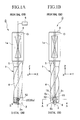
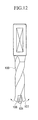
- FIGS. 1A and 1B are side views showing an embodiment of a drill of the present invention, and in particular, FIG. 1A is a side view as viewed in the Y-direction, and FIG. 1B is a side view as viewed in the X-direction.
- FIG. 2 is a diagram viewing FIG. 1A from a distal end side (the Z-direction side).
- FIG. 3 is a cross-sectional view taken along the line A-A in FIG. 1B.
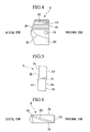
- FIG. 4 is a side view of an insert as viewed in the Y-direction
- FIG. 5 is a diagram viewing FIG. 4 from the distal end side
- the X-direction is defined as a diametric direction with respect to an axis O of a drill D in which a concave groove 6 to be explained below is formed
- the Y-direction is defined as a direction perpendicular to the X-direction and the axis O
- the Z-direction is defined as a direction parallel to the axis O, in which the positive (+) direction thereof is defined as the direction from the distal end to the proximal end of the drill D.
- the drill D includes a drill main body 1 being rotatable about the axis O, and an insert 2 detachably attached to the drill main body 1.
- the insert 2 includes cutting edge 2a.
- the drill main body 1 includes, at the proximal portion thereof, a shank portion 1a which is a large diameter portion.
- the drill main body 1 includes, at the distal portion thereof, a pair of chip discharge flutes 4 which open at a distal end face 3 of the drill main body 1. As shown in FIG.
- the chip discharge flutes 4 are formed such that the chip discharge flutes 4 are opposite each other while having the axis O therebetween, and extend toward the proximal end while being twisted about the axis O in a direction opposite to the direction of drill rotation T during a drilling operation.
- the concave groove 6 opens at the distal end face 3 of drill main body 1, and is formed so as to be concave toward the proximal end side, and so as to extend in a diametric direction with respect to the axis O. More specifically, the concave groove 6 is formed such that a portion between the walls of the chip discharge flutes 4 at the distal end that face the direction of drill rotation T is cut out along a virtual plane including the axis O and along the diametric direction (X-direction).
- the concave groove 6 includes a bottom face 6a which faces the distal end side and is perpendicular to the axis O, and a pair of inner faces 6b parallel to each other, each of which is perpendicular to the bottom face 6a and parallel to the axis O. As shown in FIG. 1B, the concave groove 6 opens toward the distal end face 3 in a rectangular shape as seen form the side. As shown in FIGS. 2 and 3, the symmetrical center of the concave groove 6 coincides with the axis O, and the concave groove 6 is formed so as to accommodate the insert 2.
- each of the guiding grooves 7 includes plural grooves, which are arranged side by side in the direction crossing the axis O, and each of which extends in the direction of the axis O.
- the guiding grooves 7 are respectively formed on the inner faces 6b.
- the guiding grooves 7 are not formed on the entire surface of the inner faces 6b, and as shown in FIG.
- each of the pair of guiding grooves 7 is formed in a region of one of the pair of inner faces 6b that faces the direction of drill rotation T and includes the vicinity of the axis O so that the guiding grooves 7 are arranged at alternating locations in the X-direction, and regions of the inner faces 6b near the axis O, which are connected to a thinning portion of the distal end face 3, are formed so as to be flat.
- the individual grooves included in the guiding grooves 7 and formed in a substantially V-shape include concave arc portions at the bottom thereof. Ridge portions formed between adjacent grooves are formed so as to have convex arc portions whose radius is made to be greater than that of the concave arc portions at the bottom.
- the drill main body 1 is provided with a flow path 5 that extends along the axis O.
- the flow path 5 is formed so as to connect a proximal end face 8 of the drill main body 1 and the bottom face 6a of the concave groove 6.
- a machining oil supply unit 9 which is provided outside the drill main body 1 to supply machining oil (fluid) to the flow path 5, is connected to a portion of the flow path 5 at the proximal end face 8 of the drill main body 1.
- the machining oil supplied from the machining oil supply unit 9, which is provided outside the drill main body 1, to the flow path 5 is made to flow from a portion of the flow path 5 at the proximal end face 8 to the bottom face 6a of the concave groove 6 that faces the distal end side.
- concave-shaped recesses 15 which may be formed by a counterboring process so as to be concave in the bottom face 6a.
- the inner end of each of the recesses 15 is connected to the distal end of the flow path 5.
- the recesses 15 respectively extend from the distal end of the flow path 5 to portions of the pair of inner faces 6b of the concave groove 6 where the guiding grooves 7 are formed, and further extend along the inner faces 6a toward the outer periphery; however, the recesses 15 do not extend to the outer edges of the bottom face 6a, i.e., the outer periphery of the drill main body 1 at the distal end, and stop within the bottom face 6.
- portions of the recesses 15 that extend along the guiding grooves 7 on the inner face 6b of the concave groove 6 are formed so as to be concave from the inner face 6b in the direction opposite to the direction of drill rotation T.
- a cavity 16 is formed between the drill main body 1 and back face 2c of the insert 2 when the insert is disposed in the concave groove 6.
- the cavity 16 is used as a machining oil chamber for retaining the machining oil supplied through the flow path 5.
- the insert 2 is disposed in the concave groove 6 such that the proximal end face 2c thereof faces the bottom face 6a.
- the insert 2 is made of a hard material such as a cemented carbide, and is formed in a substantially pentangular plate shape as shown in FIGS. 4, 5, and 6.
- the insert 2 is attached while being engaged with the concave groove 6.
- the insert 2 includes a through hole 10 that is formed at the center of the insert 2 with respect to the X-direction so as to extend in the thickness direction (in the Y-direction). As shown in FIGS.
- the through hole 10 is positioned so as to coincide with a mounting hole 11 when the insert is disposed in the concave groove 6, the mounting hole 11 being formed at the center of the distal end portion of the drill main body with respect to the X-direction so as to extend in the Y-direction and to open at the inner face 6b of the concave groove 6.
- the mounting hole 11 extends in the Y-direction from an outer periphery of one (the upper portion with respect to the concave groove in FIG.
- the mounting hole 11 is formed as a stopped hole which does not penetrate through the drill main body 1, and a female thread is formed therein.
- the insert 2 By disposing the insert 2 in the concave groove 6 by inserting a bolt as a fixing element 12 from the one section into the mounting hole 11 and the through hole 10, and by screwing the bolt into the female thread, the insert 2 is fixed and connected to the drill main body 1 while the countersunk-head of the bolt as the fixing element 12 firmly contacts the reduced diameter portion, as shown in FIG. 3.
- the through hole 10 and the mounting hole 11 are disposed at the center with respect to the X-direction, and extend in the direction perpendicular to the axis O for the case of the fixing element (bolt) 12 that is inserted into and engaged with the through hole 10 and the mounting hole 11.
- convex portions 13 which are engageable with the guiding grooves 7 of the drill main body 1.
- the convex portions 13 extend in the direction of the axis O, i.e., the ridgelines thereof extend in the direction of the axis O, and are arranged side by side in the direction crossing the axis O.
- the convex portions 13 are formed in regions which correspond to the portions of the concave groove 6 in which the guiding grooves are formed in a state in which the insert 2 is disposed in the concave groove 6.
- the convex portions 13 are respectively formed on the outer surfaces 2b of the insert 2, and the convex portions 13 are formed in the regions of the pair of outer surfaces 2b that face the direction opposite to the direction of drill rotation T and include the vicinity of the axis O so that the convex portions 13 are arranged at two alternating locations in the X-direction.
- the regions of the outer surfaces 2b of the insert 2 corresponding to the inner faces 6b which are formed to be flat, and which are connected to the thinning portion, are formed to be flat so as to make a surface contact with the flat portions of the concave groove 6. As shown in FIG.
- the ridge portions of the convex portions 13 formed in a substantially V-shape include convex arc portions.
- Valley portions formed between adjacent convex portions 13 are formed so as to have concave arc portions whose radii are made to be less than those of the convex arc portions, and the included angle of the V-shape of the convex portions 13 is the same as the included angle of the V-shape of the grooves of the guiding grooves 7.
- gaps 14 are formed between the convex portions 13 formed on the insert 2 and the guiding grooves 7 formed on the concave groove 6 of the drill main body 1, and at the apexes and valleys of the convex portions 13.
- the radii of the convex arcs of the ridge portions of the convex portions 13 are set to be greater than those of the concave arcs of the grooves of the guiding grooves 7, and the radii of the concave arcs of the bottoms between the adjacent convex portions 13 are set to be less than those of the convex arcs of the ridge portions between the adjacent grooves of the guiding grooves 7.
- the gaps 14 are formed between the ridge portions of the convex portions 13 and the bottom portions of the grooves in the guiding grooves 7, and between the valleys between the adjacent convex portions 13 and the ridge portions between the adjacent grooves in the guiding grooves 7.
- the size of the gaps 14 is determined so that machining oil is allowed to flow therethrough, i.e., machining oil is allowed to flow between the distal portion of the insert 2 and the proximal portion thereof, and thus, when the insert 2 is disposed in the concave groove 6, the machining oil, which is supplied to the bottom face 6a of the concave groove 6 via the flow path 5, is allowed to flow through the gaps 14. More specifically, the machining oil, which is supplied to the concave groove 6 via the flow path 5, is allowed to flow out at the distal portion of the insert 2.
- the cavity 16 is formed in a portion of the bottom face 6a of the concave groove 6 which corresponds to the connection region between the guiding grooves 7 and the convex portions 13. More specifically, portions of the recesses 15 forming the cavity 16 that extend along the guiding grooves 7 in the inner faces 6b of the concave groove 6 are formed so as to be concave from the inner faces 6b in the direction opposite to the direction of drill rotation T. Accordingly, when the insert 2 is disposed in the concave groove 6, the cavity 16 is connected, over the region where the cavity 16 is formed, to the gaps 14 which are formed between the convex portions 13 and the grooves of the guiding grooves 7.
- the distal end face of the insert 2 is formed in an isosceles triangular shape (V-shape), i.e., the distal end face of the insert 2 is formed so as to extend toward the proximal end side as it extends outward.
- the cutting edges 2a are respectively formed on the intersecting ridges between the distal end face and the rake faces 20, of the outer surfaces 2b of the insert 2, which face the direction of drill rotation T in a state in which the insert 2 is attached to the drill main body 1.
- the rake face 20 becomes narrower and is inclined toward the opposite outer surface 2b as it extends toward the proximal end of the insert 2, and is connected to the wall that faces the direction of drill rotation T in the mounted state.
- the convex portions 13 are formed on the outer surfaces 2b where the rake faces 20 are not formed.
- the back face 2c of the insert 2 extends in the direction perpendicular to the axis O in a state in which the insert 2 is attached to the drill main body 1, and makes a surface contact with the bottom face 6a of the concave groove 6 where the recesses 15 are not formed.
- the insert 2 When the insert 2 is to be attached to the drill main body 1, the insert 2 is oriented so that the extending direction of the through hole 10 of the insert 2 coincides with the extending direction of the mounting hole 11 of the drill main body 1, and then the insert 2 is inserted into the concave groove 6 from the side of the distal end face 3 (from the open side) in the +Z direction, i.e., in the insertion direction S, which is the direction of the axis O toward the proximal end (refer to FIG. 1A).
- the insert 2 When the insert 2 is inserted into the concave groove 6, the insert 2 is inserted in a sliding manner while engaging the convex portions 13 on the outer surfaces 2b of the insert 2 with the guiding grooves 7 on the inner surfaces 6b of the concave groove 6.
- the back face 2c of the insert 2 makes a surface contact with the bottom face 6a of the concave groove 6. Because the position at which the back face 2c of the insert 2 contacts the bottom face 6a of the concave groove 6 is determined such that the through hole 10 of the insert 2 coincides with the mounting hole 11 of the drill main body 1, at this stage, the fixing element 12 can be inserted into the through hole 10 and the mounting hole 11, and the insert 2 can be connected and fixed to the drill main body 1 by screwing the fixing element 12 such as a bolt into the mounting hole 11 having the female thread.
- the thickness of the insert 2 where the rake faces 20 are formed is set to be less than the thickness of the insert 2 where the convex portions 13 are formed (i.e., the thickness at the apexes of the convex portions 13). Accordingly, the insertion operation is not hindered when the insert 2 is inserted into the concave groove 6 while making the convex portions 13 slide with respect to the guiding grooves 7.
- the fixing element 12 is unscrewed from the mounting hole 11 and removed therefrom, and the insert 2 is removed from the concave groove 6 so that the insert 2 is separated from the drill main body 1.
- a drilling operation is applied to a workpiece while supplying machining oil from the machining oil supply unit 9 to the flow path 5 of the drill main body 1.
- the machining oil supplied to the flow path 5 is supplied from the end of the flow path 5 to the cavity 16 acting as a machining oil chamber. Because the cavity 16 is connected to the gaps 14, the machining oil is allowed to flow out at the distal end of the insert 2 via the gaps 14. Accordingly, the drilling operation can be performed while supplying machining oil to the workpiece.
- the insert 2 can be easily attached to the drill main body 1 just by inserting the insert 2 while engaging the convex portions 13 with the guiding grooves 7. Moreover, the aligning accuracy of the insert 2 with respect to the drill main body 1 can be improved.
- the insert 2 is tightened by the fixing element 12 (bolt) such that the concave groove 6 is made narrower, and the insert 2 is pressed from the Y-direction to the direction slightly inclined with respect to the direction connecting the pair of inner surfaces 6b and 6b of the concave groove 6 in which the guiding grooves 7 are formed, the convex portions 13 can be further reliably engaged with the guiding grooves 7, and the aligning accuracy can be further improved.
- the insert 2 will not move with respect to the drill main body 1 when a workpiece is machined by the insert 2 while rotating the drill main body 1, and thus, the rotational force of the drill main body 1 is surely and efficiently transmitted to the insert 2. Accordingly, the machining process is stabilized, and high machining accuracy can be achieved.
- the flow path 5 which connects the bottom face 6a of the concave groove 6 that faces the distal end side to the outside of the drill main body 1, is formed in the drill main body 1, and the drill main body 1 and the insert 2 are formed so that the gaps 14 are formed between the guiding grooves 7 and the convex portions 13 in the engaged state, the machining oil supplied from the flow path 5 is allowed to flow out at the distal end of the insert 2 via the gaps 14; therefore, the machining oil can be stably supplied to the distal end of the insert 2 without forming the branched paths for supplying machining oil in the distal end portion of the drill main body, as shown in FIG. 11. Because a flow path is not formed in the distal end portion of the drill main body 1, the strength of the drill main body 1 is maintained, a problem such as deformation can be avoided, and the manufacturing processes of the drill main body 1 can be facilitated.
- the insert 2 contacts the drill main body 1 in such a manner that the gaps 14 are formed at only locations corresponding to the apexes (ridgelines) of the convex portions 13 (i.e., locations corresponding to the valleys (groove bottoms) of the guiding grooves 7) and the valleys between the convex portions 13 adjacent to each other (i.e., locations corresponding to ridgelines of the adjacent grooves of the guiding grooves 7), and the side surfaces of the convex portions 13 make a surface contact with the walls of the guiding grooves 7 at other locations, the contact area between the insert 2 and the drill main body 1 is sufficiently ensured, and the insert 2 can be stably attached to the drill main body 1.
- the cavity 16, acting as a machining oil chamber is provided in the bottom face 6a of the concave groove 6 so as to be connected to the gaps 14, machining oil can be stably supplied to the gaps 14, and thus the supply of machining oil to the distal end of the insert 2 during a machining process is ensured.
- machining oil is supplied to the distal end of the insert 2 via the gaps 14 formed between the insert 2 and the drill main body 1; however, as shown in FIG. 8, branched paths 103, which are branched from the flow path 5 and are connected to openings 104 at the distal end face 3 of the drill main body 1, may be formed.
- the branched paths shown in FIG. 11 and the gaps 14 according to the present invention may be simultaneously employed.
- the openings 104 of the branched paths 103 may be formed in the outer peripheral surface of the distal end portion of the drill main body 1.
- the total cross-sectional area of the gaps 14 be less than that of the branched paths 103, so that machining oil can be supplied through the gaps 14, which open at the vicinity of the cutting edges 2a, at higher pressure.
- the strength of the distal end portion of the drill main body 1 is ensured since the branched paths 103 are not provided.
- the gaps 14 may be formed at only one of the ridge portions of the convex portions 13 (i.e., the groove bottoms of the guiding grooves 7) and the valleys between the convex portions 13 adjacent to each other (i.e., the ridgelines of the adjacent grooves of the guiding grooves 7).
- compressed air acting as a fluid may be supplied instead of supplying machining oil from the machining oil supply unit 9.
- FIG. 9A is a side view showing an insert of this embodiment
- FIG. 9B is an enlarged perspective view showing the main part.
- the insert 2 is formed in a substantially pentangular plate shape, and is to be inserted into the concave groove 6 of the drill main body 1.
- the convex portions 13 are formed so as to extend in the direction of insertion into the concave groove 6 (i.e., in the direction of axis O or in the Z-direction), i.e., the ridgelines thereof coincide with the direction of insertion.
- the convex portions 13 are arranged side by side in the direction crossing the direction of insertion (i.e., in the X-direction).
- the convex portions 13 are formed at locations corresponding to the guiding grooves 7 of the concave groove 6 in a state in which the insert 2 is disposed in the concave groove 6.
- the convex portions 13 are respectively provided with tapered portions 30 (30A to 30D) each of which is inclined toward the proximal end face 2c of the insert 2.
- the tapered portions 30 are formed in such a manner that the thickness of the insert 2 becomes less (i.e., the height of the convex portions 13 is gradually decreased) as it extends toward the proximal end face 2c of the insert 2.
- the lengths of the tapered portions 30A to 30D formed on the convex portions 13, when measured in the direction of insertion, i.e., the lengths La to Ld of the tapered portions 30A to 30D measured in the Z-direction, are set so as to be different from each other.
- the lengths La to Ld of the tapered portions 30A to 30D are set so as to be gradually decreased, in the direction crossing the direction of insertion, from the center of the outer surface 2b with respect to the X-direction toward an end of the outer surface 2b.
- the length Ld of the tapered portion 30D at the center of the outer surface 2b with respect to the X-direction is the greatest, and the lengths Lc, Lb, and La are set so as to be gradually decreased toward the end of the outer surface 2b with respect to the X-direction.
- angles ⁇ a to ⁇ d between the lines parallel to the Z-axis (axis O) and the surfaces of the tapered portions 30A to 30D are set such that the angle ⁇ d corresponding to the tapered portion 30D at the center with respect to the X-direction is the smallest, and the angles ⁇ c, ⁇ b, and ⁇ a of the tapered portions 30 are set so as to be gradually increased toward the end of the outer surface 2b with respect to the X-direction.
- the tip sides (-Z sides) of the tapered portions 30A to 30D are arranged on a straight line M, and the angle between the line M and the X-axis is set to be ⁇ M (refer to FIG. 9A).
- the back ends of the tapered portions 30A to 30D coincide with the proximal end face 2c of the insert 2, which is perpendicular to the axis O. Accordingly, the line M is inclined toward the proximal end face 2c as it extends from the center with respect to the X-direction toward the end of insert 2, as shown in FIG. 9A.
- the tapered portions 30A to 30D are formed such that the back ends of the convex portions 13 are chamfered by a single plane including the line M.
- the distal end portion of the drill main body 1 is formed in a substantially V-shape as seen from the side, and the angle between the distal end face 3 and the X-axis is substantially equal to the angle ⁇ M between the line M and the X-axis.
- the lengths La to Ld of the tapered portions 30A to 30D are set so that the line M, which is defined by the tapered portions 30A to 30D, substantially coincides with the inclination (shape) of the distal end face 3.
- the proximal end face 2c of the insert 2 is disposed so as to be opposite the concave groove 6.
- the angle between the distal end face 3 and the X-axis is set to be substantially equal to the angle ⁇ M between the line M and the X-axis.
- the insert 2 is inserted into the concave groove 6.
- the angle between the distal end face 3 and the X-axis is set to be substantially equal to the angle ⁇ M between the line M and the X-axis
- the convex portions 13 formed on the insert 2 respectively and simultaneously engage the guiding grooves 7 formed in the concave groove 6. More specifically, because the convex portions 13 simultaneously engage the guiding grooves 7 during the inserting operation, the inserting operation of the insert 2 can be smoothly and steadily performed.
- the insert 2 is further inserted so as to be disposed in the concave groove 6 as shown in FIG. 10C.
- the lengths La to Ld of the tapered portions 30A to 30D are set so that the line M substantially coincides with the inclination (shape) of the distal end face 3, the convex portions 13 respectively and simultaneously engage the guiding grooves 7 formed in the concave groove 6 during the inserting operation.
- the lengths La to Ld of the tapered portions 30A to 30D are set depending on the shape of the distal end face 3 so that the convex portions 13 respectively and simultaneously engage the guiding grooves 7 formed in the concave groove 6.
- the line (line M) defined by connecting the tip ends (ends at -Z side) of the tapered portions 30A to 30D is also set in a W-shape.
- a through groove 31 which has a U-shaped cross section while opening at the proximal end face 2c, and which penetrates through the insert 2 between the outer surfaces 2b, is provided at the center of the insert 2 with respect to the X-direction, instead of the through hole 10 of the insert 2. Due to the through groove 31, when the insert 2 is to be removed, the insert 2 can be removed without completely removing the fixing element (bolt) 12 from the drill main body 1. Furthermore, in this embodiment, the ridge portions of the convex portions 13 are chamfered by a plane that extends parallel to the outer surfaces 2b, i.e., a plane perpendicular to the Y-axis.
- the cross-sectional area of the gaps 14 formed between the ridge portions and the groove bottoms of the guiding grooves 7 can be increased, so that a greater amount of predetermined fluid such as machining oil can be supplied to the distal end portion of the drill main body 1, while maintaining the stable attachment of the insert 2.
- the ridge portions between the grooves adjacent to each other may be similarly chamfered, so that both the ridge portions of the convex portions 13 and the ridge portions between the grooves of the guiding grooves 7 are chamfered by planes.
- the throwaway insert includes convex portions on the outer surface thereof that are engageable with the guiding grooves, and a serrated structure is constituted by the guiding grooves and the convex portions, the insert can be easily attached to the drill main body just by inserting the insert from the distal end in a sliding manner while engaging the convex portions with the guiding grooves, and the aligning accuracy of the insert with respect to the drill main body can be improved.
- the insert will not move with respect to the drill main body when a workpiece is machined by the insert while rotating the drill main body, and thus, the rotational force of the drill main body is surely and efficiently transmitted to the insert.
- the insertion operation into the concave groove of the drill main body can be smoothly performed. Accordingly, a stable drilling operation can be performed while maintaining preferable machining accuracy.
Landscapes
- Engineering & Computer Science (AREA)
- Mechanical Engineering (AREA)
- Drilling Tools (AREA)
Abstract
Description
- The present invention relates to a drill having a throwaway insert (hereinafter referred to as an insert) which is detachably engageable with grooves formed in a distal end face of a drill main body, and relates to such an insert.
- Conventionally, a drill is known in which a groove is formed on the distal end face of the main body of the drill, an insert is attached to the groove in a detachable manner, and the insert after having been used is thrown away without resharpening, so that resharpening processes for tools are omitted, and the time for changing tools is reduced. Such a technology in drills is disclosed, for example, in Japanese Unexamined Patent Application, First Publication No. H11-197923. In the drill disclosed in this document, an attachment hole having a circular hole shape is formed on a bottom face of a groove that is directed to a distal end, and an insert is provided with a cylindrical shank portion at a back face thereof that faces the bottom face. The insert is attached to the drill main body by inserting the shank portion into the attachment hole. The shank portion has a notch, and an engagement element is provided inside the attachment hole; therefore, the engagement element engages the notch when the shank portion is inserted into the attachment hole, and thus the insert is fixed to the drill main body.
- In the above-mentioned drill, because the insert can be fixed to the drill main body just by inserting the shank portion into the attachment hole, the process of attaching the insert is simplified, and thus efficiency is obtained; however, a problem is encountered in that the shank portion may be broken if it is too thin since the connection between the insert and the drill main body is achieved by the shank portion. Moreover, aligning (centering) of the insert with respect to the drill main body is achieved only by the engagement of the shank portion with the attachment hole; therefore, the aligning accuracy may be insufficient, which may lead to degradation in machining accuracy of the drill with respect to a workpiece.
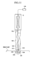
- In addition, when a workpiece is machined by a drill, in general, machining oil is supplied during the machining process. For this, conventionally, as shown in FIG. 11, a
flow path 102 is formed in a drillmain body 100 so as to extend in the direction of an axis O of the drillmain body 100,branched paths 103 are branched in two directions from theflow path 102 at a distal portion thereof, thebranched paths 103 are connected toopenings 104 which are formed in adistal end face 107 of the drillmain body 100, and machining oil is provided in a machiningoil supply section 105 which is connected to the proximal end of theflow path 102 so that machining oil is supplied between the workpiece and aninsert 101 via theflow path 102,branched paths 103, andopenings 104. However, because thebranched paths 103 are formed in the distal portion of the drillmain body 100, the strength of the distal portion, which is made thinner and weakened by agroove 106, is further decreased due to thebranched paths 103; therefore, another problem is encountered in that the distal portion of the drillmain body 100 may deform outwardly so as to be away from thegroove 106, as shown in FIG. 12. Furthermore, the formation of thebranched paths 103 necessitates a greater number of manufacturing processes and more complicated manufacturing processes. - The present invention was conceived in view of the above circumstances, and objects thereof are to provide a drill which improves the aligning accuracy between a drill main body thereof and an insert, and which achieves a stable machining operation while maintaining the strength of the drill main body, and to provide an insert which is detachably attached to such a drill.
- In order to achieve the above objects, the present invention provides a drill including: a drill main body being rotatable about an axis; and a throwaway insert detachably attached to the drill main body, wherein the drill main body includes a concave groove which opens at a distal end face thereof, the concave groove includes guiding grooves extending in the direction of the axis on an inner surface thereof, the throwaway insert includes convex portions on an outer surface thereof that are engageable with the guiding grooves, the concave groove is formed so as to accommodate the throwaway insert, and the throwaway insert is attached to the drill main body by being inserted into the concave groove along a direction from the distal end face to the concave groove while engaging the convex portions with the guiding grooves.
- According to the drill of the present invention, because the guiding grooves extending in the direction of the axis are formed on the inner surface of the concave groove, the throwaway insert includes convex portions on the outer surface thereof that are engageable with the guiding grooves, and a serrated structure is constituted by the guiding grooves and the convex portions, the insert can be easily attached to the drill main body just by inserting the insert from the distal end in a sliding manner while engaging the convex portions with the guiding grooves, and the aligning accuracy of the insert with respect to the drill main body can be improved. In addition, because the serrated structure is employed, the insert will not move with respect to the drill main body when a workpiece is machined by the insert while rotating the drill main body, and thus, the rotational force of the drill main body is surely and efficiently transmitted to the insert.
- In this case, it is preferable that the drill main body be provided with a flow path which extends from a bottom face of the concave groove that faces the distal end face, and which opens outside the drill main body so as to allow a predetermined fluid to flow therethrough, and a gap be formed between the guiding grooves and the convex portions engaging with each other, which allows the fluid to flow between a distal end of the throwaway insert and a proximal end thereof that faces the bottom face of the concave groove. Accordingly, unlike in conventional practice, a fluid can be stably supplied to the end of the insert without providing a flow path (branched paths) for machining oil (a fluid) in the distal end portion of the drill main body. Because a flow path is not formed in the drill main body, the strength of the drill main body is maintained, a problem such as deformation can be avoided, and the manufacturing processes can be facilitated.
- Even when gaps are provided, the attachment of the insert to the drill main body is stabilized since the contact area between the insert and the concave groove is ensured due to the serrated structure.
- Moreover, in this case, it is more preferable that the bottom face be provided with a cavity which is connected to the gap. Accordingly, the cavity can be used as a machining oil chamber, and the supply of the machining oil to the gap is stabilized. Furthermore, at least one of ridge portions of the convex portions and ridge portions between the guiding grooves may be chamfered so as to have a flat surface, whereby a large cross section of the gap can be ensured, and a greater amount of fluid such as machining oil can be supplied.
- In addition, it is preferable that the convex portions be formed such that ridge portions thereof extend in the direction of the axis and are arranged side by side in the direction crossing the axis, and each of the convex portions is provided with a tapered portion that is inclined toward the direction of insertion. Accordingly, the aligning accuracy of the insert with respect to the drill main body can be improved, and the insertion operation can be smoothly performed.
- The present invention provides an insert that is insertable into a concave groove formed at a distal end portion of a drill main body, the insert including convex portions formed on an outer surface of the throwaway insert such that ridgelines thereof extend in the direction of insertion, wherein the convex portions are arranged side by side, on the outer surface, in a direction crossing the direction of insertion.
- According to the insert of the present invention, provided that guiding grooves extending in the direction of insertion are formed on an inner surface of the concave groove formed in the drill main body, because the convex portions are formed on the outer surface of the insert, a serrated structure is constituted by the guiding grooves and the convex portions; therefore, the insert can be easily attached to the drill main body just by inserting the insert from the distal end in a sliding manner while engaging the convex portions with the guiding grooves, and the aligning accuracy of the insert with respect to the drill main body can be improved.
- In the insert of the present invention, it is preferable that each of the convex portions be provided with a tapered portion that is inclined toward the direction of insertion. Accordingly, the insertion operation into the concave groove can be smoothly performed.
- In addition, in the insert of the present invention, it is preferable that the lengths of the tapered portions formed on the convex portions, when measured in the direction of insertion, be set to be different from each other. In this case, the lengths of the tapered portions may be set depending on the shape of the distal end portion of the drill main body. Accordingly, the insertion operation can be smoothly performed since, when the insert is inserted into the concave groove of the drill main body, the convex portions can be respectively and simultaneously engaged with the guiding grooves in the concave groove.
- In this case, it is more preferable that the lengths of the tapered portions be set so as to be gradually decreased, in the direction crossing the direction of insertion, from the center of the outer surface toward an end of the outer surface. More specifically, whereas the shape of the concave groove at an insertion aperture thereof as seen from the side is normally configured to be a V-shape, the convex portions can be respectively and simultaneously engaged with the concave groove by setting the lengths of the tapered portions so as to be gradually decreased, in the direction crossing the direction of insertion, from the center of the outer surface toward the end of the outer surface.
-
- FIGS. 1A and 1B are side views showing an embodiment of a drill of the present invention.
- FIG. 2 is a diagram showing the drill in FIGS. 1A and 1B as viewed from a distal end side.
- FIG. 3 is a cross-sectional view taken along the line A-A in FIG. 1B.
- FIG. 4 is a side view of an insert.
- FIG. 5 is a diagram showing the insert as viewed from a distal end side.
- FIG. 6 is a side view of an insert.
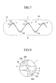
- FIG. 7 is a diagram for explaining a gap.
- FIG. 8 is a diagram showing another embodiment of a drill of the present invention.
- FIGS. 9A and 9B are diagrams showing another embodiment of an insert of the present invention.
- FIGS. 10A, 10B, and 10C are diagrams for explaining an insertion operation of the insert shown in FIGS. 9A and 9B into a concave groove formed in a drill main body.
- FIG. 11 is a diagram showing a conventional drill.
- FIG. 12 is a diagram showing the problems of the conventional drill.
-
- A drill and an insert of the present invention will be described below with reference to the accompanying drawings. FIGS. 1A and 1B are side views showing an embodiment of a drill of the present invention, and in particular, FIG. 1A is a side view as viewed in the Y-direction, and FIG. 1B is a side view as viewed in the X-direction. FIG. 2 is a diagram viewing FIG. 1A from a distal end side (the Z-direction side). FIG. 3 is a cross-sectional view taken along the line A-A in FIG. 1B. FIG. 4 is a side view of an insert as viewed in the Y-direction, FIG. 5 is a diagram viewing FIG. 4 from the distal end side, and FIG. 6 is a side view of the insert as viewed in the X-direction. Note that the X-direction is defined as a diametric direction with respect to an axis O of a drill D in which a
concave groove 6 to be explained below is formed, the Y-direction is defined as a direction perpendicular to the X-direction and the axis O, and the Z-direction is defined as a direction parallel to the axis O, in which the positive (+) direction thereof is defined as the direction from the distal end to the proximal end of the drill D. - In FIGS. 1A and 1B, the drill D includes a drill
main body 1 being rotatable about the axis O, and aninsert 2 detachably attached to the drillmain body 1. Theinsert 2 includes cuttingedge 2a. The drillmain body 1 includes, at the proximal portion thereof, ashank portion 1a which is a large diameter portion. On the other hand, the drillmain body 1 includes, at the distal portion thereof, a pair of chip discharge flutes 4 which open at adistal end face 3 of the drillmain body 1. As shown in FIG. 2, the chip discharge flutes 4 are formed such that the chip discharge flutes 4 are opposite each other while having the axis O therebetween, and extend toward the proximal end while being twisted about the axis O in a direction opposite to the direction of drill rotation T during a drilling operation. - At the distal end portion of the drill
main body 1, theconcave groove 6 is formed. Theconcave groove 6 opens at thedistal end face 3 of drillmain body 1, and is formed so as to be concave toward the proximal end side, and so as to extend in a diametric direction with respect to the axis O. More specifically, theconcave groove 6 is formed such that a portion between the walls of the chip discharge flutes 4 at the distal end that face the direction of drill rotation T is cut out along a virtual plane including the axis O and along the diametric direction (X-direction). Theconcave groove 6 includes abottom face 6a which faces the distal end side and is perpendicular to the axis O, and a pair ofinner faces 6b parallel to each other, each of which is perpendicular to thebottom face 6a and parallel to the axis O. As shown in FIG. 1B, theconcave groove 6 opens toward thedistal end face 3 in a rectangular shape as seen form the side. As shown in FIGS. 2 and 3, the symmetrical center of theconcave groove 6 coincides with the axis O, and theconcave groove 6 is formed so as to accommodate theinsert 2. - As shown in FIGS 1A, 1B, and 2, on the
inner faces 6b of theconcave groove 6, there are formed guidinggrooves 7 which extend in the direction of the axis O. Each of the guidinggrooves 7 includes plural grooves, which are arranged side by side in the direction crossing the axis O, and each of which extends in the direction of the axis O. The guidinggrooves 7 are respectively formed on theinner faces 6b. The guidinggrooves 7 are not formed on the entire surface of theinner faces 6b, and as shown in FIG. 2, each of the pair of guidinggrooves 7 is formed in a region of one of the pair ofinner faces 6b that faces the direction of drill rotation T and includes the vicinity of the axis O so that the guidinggrooves 7 are arranged at alternating locations in the X-direction, and regions of theinner faces 6b near the axis O, which are connected to a thinning portion of thedistal end face 3, are formed so as to be flat. As shown in FIG. 7, the individual grooves included in the guidinggrooves 7 and formed in a substantially V-shape include concave arc portions at the bottom thereof. Ridge portions formed between adjacent grooves are formed so as to have convex arc portions whose radius is made to be greater than that of the concave arc portions at the bottom. - As shown in FIGS. 1A and 1B, the drill
main body 1 is provided with aflow path 5 that extends along the axis O. Theflow path 5 is formed so as to connect aproximal end face 8 of the drillmain body 1 and thebottom face 6a of theconcave groove 6. As shown in FIG. 1A, a machiningoil supply unit 9, which is provided outside the drillmain body 1 to supply machining oil (fluid) to theflow path 5, is connected to a portion of theflow path 5 at theproximal end face 8 of the drillmain body 1. The machining oil supplied from the machiningoil supply unit 9, which is provided outside the drillmain body 1, to theflow path 5 is made to flow from a portion of theflow path 5 at theproximal end face 8 to thebottom face 6a of theconcave groove 6 that faces the distal end side. - As shown in FIGS. 1B and 2, on the
bottom face 6a of theconcave groove 6, there are formed concave-shapedrecesses 15 which may be formed by a counterboring process so as to be concave in thebottom face 6a. The inner end of each of therecesses 15 is connected to the distal end of theflow path 5. Therecesses 15 respectively extend from the distal end of theflow path 5 to portions of the pair ofinner faces 6b of theconcave groove 6 where the guidinggrooves 7 are formed, and further extend along the inner faces 6a toward the outer periphery; however, therecesses 15 do not extend to the outer edges of thebottom face 6a, i.e., the outer periphery of the drillmain body 1 at the distal end, and stop within thebottom face 6. As shown in FIGS. 1B and 2, portions of therecesses 15 that extend along the guidinggrooves 7 on theinner face 6b of theconcave groove 6 are formed so as to be concave from theinner face 6b in the direction opposite to the direction of drill rotation T. Due to therecess 15, acavity 16 is formed between the drillmain body 1 and back face 2c of theinsert 2 when the insert is disposed in theconcave groove 6. Thecavity 16 is used as a machining oil chamber for retaining the machining oil supplied through theflow path 5. - The
insert 2 is disposed in theconcave groove 6 such that the proximal end face 2c thereof faces thebottom face 6a. Theinsert 2 is made of a hard material such as a cemented carbide, and is formed in a substantially pentangular plate shape as shown in FIGS. 4, 5, and 6. Theinsert 2 is attached while being engaged with theconcave groove 6. Theinsert 2 includes a throughhole 10 that is formed at the center of theinsert 2 with respect to the X-direction so as to extend in the thickness direction (in the Y-direction). As shown in FIGS. 1A, 1B, and 3, the throughhole 10 is positioned so as to coincide with a mountinghole 11 when the insert is disposed in theconcave groove 6, the mountinghole 11 being formed at the center of the distal end portion of the drill main body with respect to the X-direction so as to extend in the Y-direction and to open at theinner face 6b of theconcave groove 6. The mountinghole 11 extends in the Y-direction from an outer periphery of one (the upper portion with respect to the concave groove in FIG. 3) of the two sections of the distal end portion of the drill main body which are formed by being divided by theconcave groove 6 while the diameter thereof is reduced in a tapered manner, i.e., via a reduced diameter portion thereof, penetrates the one section, opens at theinner face 6b of the one section of theconcave groove 6, further extends across theconcave groove 6, and extends through theinner face 6b of the other section of the distal end portion of the drillmain body 1 in the Y-direction, i.e., coaxially with a portion of the mountinghole 11 in the one section. The mountinghole 11 is formed as a stopped hole which does not penetrate through the drillmain body 1, and a female thread is formed therein. By disposing theinsert 2 in theconcave groove 6 by inserting a bolt as a fixingelement 12 from the one section into the mountinghole 11 and the throughhole 10, and by screwing the bolt into the female thread, theinsert 2 is fixed and connected to the drillmain body 1 while the countersunk-head of the bolt as the fixingelement 12 firmly contacts the reduced diameter portion, as shown in FIG. 3. The throughhole 10 and the mountinghole 11 are disposed at the center with respect to the X-direction, and extend in the direction perpendicular to the axis O for the case of the fixing element (bolt) 12 that is inserted into and engaged with the throughhole 10 and the mountinghole 11. - As shown in FIGS. 4 and 5, on the
outer surfaces 2b of theinsert 2, there are formedconvex portions 13 which are engageable with the guidinggrooves 7 of the drillmain body 1. Theconvex portions 13 extend in the direction of the axis O, i.e., the ridgelines thereof extend in the direction of the axis O, and are arranged side by side in the direction crossing the axis O. Theconvex portions 13 are formed in regions which correspond to the portions of theconcave groove 6 in which the guiding grooves are formed in a state in which theinsert 2 is disposed in theconcave groove 6. More specifically, theconvex portions 13 are respectively formed on theouter surfaces 2b of theinsert 2, and theconvex portions 13 are formed in the regions of the pair ofouter surfaces 2b that face the direction opposite to the direction of drill rotation T and include the vicinity of the axis O so that theconvex portions 13 are arranged at two alternating locations in the X-direction. The regions of theouter surfaces 2b of theinsert 2 corresponding to theinner faces 6b which are formed to be flat, and which are connected to the thinning portion, are formed to be flat so as to make a surface contact with the flat portions of theconcave groove 6. As shown in FIG. 7, in cross-sectional view taken along a plane perpendicular to the axis O, the ridge portions of theconvex portions 13 formed in a substantially V-shape include convex arc portions. Valley portions formed between adjacentconvex portions 13 are formed so as to have concave arc portions whose radii are made to be less than those of the convex arc portions, and the included angle of the V-shape of theconvex portions 13 is the same as the included angle of the V-shape of the grooves of the guidinggrooves 7. - Moreover, as shown in FIG. 7, in a state in which the
insert 2 is disposed in theconcave groove 6 while theconvex portions 13 are engaged with the guidinggrooves 7,gaps 14 are formed between theconvex portions 13 formed on theinsert 2 and the guidinggrooves 7 formed on theconcave groove 6 of the drillmain body 1, and at the apexes and valleys of theconvex portions 13. More specifically, the radii of the convex arcs of the ridge portions of theconvex portions 13 are set to be greater than those of the concave arcs of the grooves of the guidinggrooves 7, and the radii of the concave arcs of the bottoms between the adjacentconvex portions 13 are set to be less than those of the convex arcs of the ridge portions between the adjacent grooves of the guidinggrooves 7. By engaging theconvex portions 13 with the guidinggrooves 7 so that the walls of the grooves in the guidinggrooves 7 and side surfaces of theconvex portions 13 having the same included angle of the V-shape as that of the guidinggrooves 7 make a surface contact therebetween, thegaps 14 are formed between the ridge portions of theconvex portions 13 and the bottom portions of the grooves in the guidinggrooves 7, and between the valleys between the adjacentconvex portions 13 and the ridge portions between the adjacent grooves in the guidinggrooves 7. The size of thegaps 14 is determined so that machining oil is allowed to flow therethrough, i.e., machining oil is allowed to flow between the distal portion of theinsert 2 and the proximal portion thereof, and thus, when theinsert 2 is disposed in theconcave groove 6, the machining oil, which is supplied to thebottom face 6a of theconcave groove 6 via theflow path 5, is allowed to flow through thegaps 14. More specifically, the machining oil, which is supplied to theconcave groove 6 via theflow path 5, is allowed to flow out at the distal portion of theinsert 2. - In addition, the
cavity 16 is formed in a portion of thebottom face 6a of theconcave groove 6 which corresponds to the connection region between the guidinggrooves 7 and theconvex portions 13. More specifically, portions of therecesses 15 forming thecavity 16 that extend along the guidinggrooves 7 in theinner faces 6b of theconcave groove 6 are formed so as to be concave from theinner faces 6b in the direction opposite to the direction of drill rotation T. Accordingly, when theinsert 2 is disposed in theconcave groove 6, thecavity 16 is connected, over the region where thecavity 16 is formed, to thegaps 14 which are formed between theconvex portions 13 and the grooves of the guidinggrooves 7. - When the
insert 2 is disposed in theconcave groove 6, the distal end face of theinsert 2 is formed in an isosceles triangular shape (V-shape), i.e., the distal end face of theinsert 2 is formed so as to extend toward the proximal end side as it extends outward. The cutting edges 2a are respectively formed on the intersecting ridges between the distal end face and the rake faces 20, of theouter surfaces 2b of theinsert 2, which face the direction of drill rotation T in a state in which theinsert 2 is attached to the drillmain body 1. The rake face 20 becomes narrower and is inclined toward the oppositeouter surface 2b as it extends toward the proximal end of theinsert 2, and is connected to the wall that faces the direction of drill rotation T in the mounted state. Theconvex portions 13 are formed on theouter surfaces 2b where the rake faces 20 are not formed. Theback face 2c of theinsert 2 extends in the direction perpendicular to the axis O in a state in which theinsert 2 is attached to the drillmain body 1, and makes a surface contact with thebottom face 6a of theconcave groove 6 where therecesses 15 are not formed. - Next, regarding the drill D having the structure explained above, the operation for attaching the
insert 2 to the drillmain body 1 and the drilling operation will be explained below. - When the
insert 2 is to be attached to the drillmain body 1, theinsert 2 is oriented so that the extending direction of the throughhole 10 of theinsert 2 coincides with the extending direction of the mountinghole 11 of the drillmain body 1, and then theinsert 2 is inserted into theconcave groove 6 from the side of the distal end face 3 (from the open side) in the +Z direction, i.e., in the insertion direction S, which is the direction of the axis O toward the proximal end (refer to FIG. 1A). When theinsert 2 is inserted into theconcave groove 6, theinsert 2 is inserted in a sliding manner while engaging theconvex portions 13 on theouter surfaces 2b of theinsert 2 with the guidinggrooves 7 on theinner surfaces 6b of theconcave groove 6. By inserting theinsert 2, theback face 2c of theinsert 2 makes a surface contact with thebottom face 6a of theconcave groove 6. Because the position at which theback face 2c of theinsert 2 contacts thebottom face 6a of theconcave groove 6 is determined such that the throughhole 10 of theinsert 2 coincides with the mountinghole 11 of the drillmain body 1, at this stage, the fixingelement 12 can be inserted into the throughhole 10 and the mountinghole 11, and theinsert 2 can be connected and fixed to the drillmain body 1 by screwing the fixingelement 12 such as a bolt into the mountinghole 11 having the female thread. - The thickness of the
insert 2 where the rake faces 20 are formed is set to be less than the thickness of theinsert 2 where theconvex portions 13 are formed (i.e., the thickness at the apexes of the convex portions 13). Accordingly, the insertion operation is not hindered when theinsert 2 is inserted into theconcave groove 6 while making theconvex portions 13 slide with respect to the guidinggrooves 7. - When the
insert 2 is to be detached from the drillmain body 1, the fixingelement 12 is unscrewed from the mountinghole 11 and removed therefrom, and theinsert 2 is removed from theconcave groove 6 so that theinsert 2 is separated from the drillmain body 1. - After fixing the
insert 2 to the drillmain body 1, a drilling operation is applied to a workpiece while supplying machining oil from the machiningoil supply unit 9 to theflow path 5 of the drillmain body 1. The machining oil supplied to theflow path 5 is supplied from the end of theflow path 5 to thecavity 16 acting as a machining oil chamber. Because thecavity 16 is connected to thegaps 14, the machining oil is allowed to flow out at the distal end of theinsert 2 via thegaps 14. Accordingly, the drilling operation can be performed while supplying machining oil to the workpiece. - As explained above, because the guiding
grooves 7 that extend in the direction of the axis O are provided on theinner surfaces 6b of theconcave groove 6, theconvex portions 13 that are engageable with the guidinggrooves 7 are provided on theouter surfaces 2b of theinsert 2, and a serrated structure is constituted by the guidinggrooves 7 and theconvex portions 13, theinsert 2 can be easily attached to the drillmain body 1 just by inserting theinsert 2 while engaging theconvex portions 13 with the guidinggrooves 7. Moreover, the aligning accuracy of theinsert 2 with respect to the drillmain body 1 can be improved. Furthermore, because theinsert 2 is tightened by the fixing element 12 (bolt) such that theconcave groove 6 is made narrower, and theinsert 2 is pressed from the Y-direction to the direction slightly inclined with respect to the direction connecting the pair ofinner surfaces concave groove 6 in which the guidinggrooves 7 are formed, theconvex portions 13 can be further reliably engaged with the guidinggrooves 7, and the aligning accuracy can be further improved. In addition, by employing a serrated structure, theinsert 2 will not move with respect to the drillmain body 1 when a workpiece is machined by theinsert 2 while rotating the drillmain body 1, and thus, the rotational force of the drillmain body 1 is surely and efficiently transmitted to theinsert 2. Accordingly, the machining process is stabilized, and high machining accuracy can be achieved. - Moreover, because the
flow path 5, which connects thebottom face 6a of theconcave groove 6 that faces the distal end side to the outside of the drillmain body 1, is formed in the drillmain body 1, and the drillmain body 1 and theinsert 2 are formed so that thegaps 14 are formed between the guidinggrooves 7 and theconvex portions 13 in the engaged state, the machining oil supplied from theflow path 5 is allowed to flow out at the distal end of theinsert 2 via thegaps 14; therefore, the machining oil can be stably supplied to the distal end of theinsert 2 without forming the branched paths for supplying machining oil in the distal end portion of the drill main body, as shown in FIG. 11. Because a flow path is not formed in the distal end portion of the drillmain body 1, the strength of the drillmain body 1 is maintained, a problem such as deformation can be avoided, and the manufacturing processes of the drillmain body 1 can be facilitated. - Furthermore, because, in the engaged state, the
insert 2 contacts the drillmain body 1 in such a manner that thegaps 14 are formed at only locations corresponding to the apexes (ridgelines) of the convex portions 13 (i.e., locations corresponding to the valleys (groove bottoms) of the guiding grooves 7) and the valleys between theconvex portions 13 adjacent to each other (i.e., locations corresponding to ridgelines of the adjacent grooves of the guiding grooves 7), and the side surfaces of theconvex portions 13 make a surface contact with the walls of the guidinggrooves 7 at other locations, the contact area between theinsert 2 and the drillmain body 1 is sufficiently ensured, and theinsert 2 can be stably attached to the drillmain body 1. - Moreover, because the
cavity 16, acting as a machining oil chamber, is provided in thebottom face 6a of theconcave groove 6 so as to be connected to thegaps 14, machining oil can be stably supplied to thegaps 14, and thus the supply of machining oil to the distal end of theinsert 2 during a machining process is ensured. - In the above description of this embodiment, machining oil is supplied to the distal end of the
insert 2 via thegaps 14 formed between theinsert 2 and the drillmain body 1; however, as shown in FIG. 8, branchedpaths 103, which are branched from theflow path 5 and are connected toopenings 104 at thedistal end face 3 of the drillmain body 1, may be formed. In other words, the branched paths shown in FIG. 11 and thegaps 14 according to the present invention may be simultaneously employed. Moreover, theopenings 104 of the branchedpaths 103 may be formed in the outer peripheral surface of the distal end portion of the drillmain body 1. In this case, it is preferable that the total cross-sectional area of thegaps 14 be less than that of the branchedpaths 103, so that machining oil can be supplied through thegaps 14, which open at the vicinity of thecutting edges 2a, at higher pressure. On the other hand, the strength of the distal end portion of the drillmain body 1 is ensured since the branchedpaths 103 are not provided. Thegaps 14 may be formed at only one of the ridge portions of the convex portions 13 (i.e., the groove bottoms of the guiding grooves 7) and the valleys between theconvex portions 13 adjacent to each other (i.e., the ridgelines of the adjacent grooves of the guiding grooves 7). Furthermore, when dry cutting is performed on a workpiece, compressed air acting as a fluid may be supplied instead of supplying machining oil from the machiningoil supply unit 9. - Next, another embodiment of the insert according to the present invention will be explained. The same reference symbols are applied to the same or equivalent elements in the above embodiment, and explanations thereof are simplified or omitted.
- FIG. 9A is a side view showing an insert of this embodiment, and FIG. 9B is an enlarged perspective view showing the main part.
- As shown in FIG. 9A, the
insert 2 is formed in a substantially pentangular plate shape, and is to be inserted into theconcave groove 6 of the drillmain body 1. On theouter surfaces 2b of theinsert 2, there are formedconvex portions 13 which are engageable with the guidinggrooves 7 of the drillmain body 1. Theconvex portions 13 are formed so as to extend in the direction of insertion into the concave groove 6 (i.e., in the direction of axis O or in the Z-direction), i.e., the ridgelines thereof coincide with the direction of insertion. Theconvex portions 13 are arranged side by side in the direction crossing the direction of insertion (i.e., in the X-direction). Theconvex portions 13 are formed at locations corresponding to the guidinggrooves 7 of theconcave groove 6 in a state in which theinsert 2 is disposed in theconcave groove 6. - The
convex portions 13 are respectively provided with tapered portions 30 (30A to 30D) each of which is inclined toward theproximal end face 2c of theinsert 2. In other words, thetapered portions 30 are formed in such a manner that the thickness of theinsert 2 becomes less (i.e., the height of theconvex portions 13 is gradually decreased) as it extends toward theproximal end face 2c of theinsert 2. - The lengths of the
tapered portions 30A to 30D formed on theconvex portions 13, when measured in the direction of insertion, i.e., the lengths La to Ld of thetapered portions 30A to 30D measured in the Z-direction, are set so as to be different from each other. In this embodiment, as shown in FIG. 9B, the lengths La to Ld of thetapered portions 30A to 30D are set so as to be gradually decreased, in the direction crossing the direction of insertion, from the center of theouter surface 2b with respect to the X-direction toward an end of theouter surface 2b. More specifically, the length Ld of the taperedportion 30D at the center of theouter surface 2b with respect to the X-direction is the greatest, and the lengths Lc, Lb, and La are set so as to be gradually decreased toward the end of theouter surface 2b with respect to the X-direction. In addition, angles a to d between the lines parallel to the Z-axis (axis O) and the surfaces of thetapered portions 30A to 30D are set such that the angle d corresponding to the taperedportion 30D at the center with respect to the X-direction is the smallest, and the angles c, b, and a of the taperedportions 30 are set so as to be gradually increased toward the end of theouter surface 2b with respect to the X-direction. - The tip sides (-Z sides) of the
tapered portions 30A to 30D are arranged on a straight line M, and the angle between the line M and the X-axis is set to be M (refer to FIG. 9A). The back ends of thetapered portions 30A to 30D coincide with theproximal end face 2c of theinsert 2, which is perpendicular to the axis O. Accordingly, the line M is inclined toward theproximal end face 2c as it extends from the center with respect to the X-direction toward the end ofinsert 2, as shown in FIG. 9A. Thetapered portions 30A to 30D are formed such that the back ends of theconvex portions 13 are chamfered by a single plane including the line M. - On the other hand, as shown in FIG. 10A, the distal end portion of the drill
main body 1 is formed in a substantially V-shape as seen from the side, and the angle between thedistal end face 3 and the X-axis is substantially equal to the angle M between the line M and the X-axis. In other words, the lengths La to Ld of thetapered portions 30A to 30D are set so that the line M, which is defined by thetapered portions 30A to 30D, substantially coincides with the inclination (shape) of thedistal end face 3. - Next, the operation for attaching the
insert 2 having the structure explained above to theconcave groove 6 of the drillmain body 1 will be explained below with reference to FIGS. 10A, 10B, and 10C. - As shown in FIG. 10A, first, the
proximal end face 2c of theinsert 2 is disposed so as to be opposite theconcave groove 6. As explained above, the angle between thedistal end face 3 and the X-axis is set to be substantially equal to the angle M between the line M and the X-axis. - Then, the
insert 2 is inserted into theconcave groove 6. As shown in FIG. 10B, during the insertion of theinsert 2 into theconcave groove 6, because the angle between thedistal end face 3 and the X-axis is set to be substantially equal to the angle M between the line M and the X-axis, theconvex portions 13 formed on theinsert 2 respectively and simultaneously engage the guidinggrooves 7 formed in theconcave groove 6. More specifically, because theconvex portions 13 simultaneously engage the guidinggrooves 7 during the inserting operation, the inserting operation of theinsert 2 can be smoothly and steadily performed. Then, theinsert 2 is further inserted so as to be disposed in theconcave groove 6 as shown in FIG. 10C. - In this embodiment, because the lengths La to Ld of the
tapered portions 30A to 30D are set so that the line M substantially coincides with the inclination (shape) of thedistal end face 3, theconvex portions 13 respectively and simultaneously engage the guidinggrooves 7 formed in theconcave groove 6 during the inserting operation. When thedistal end face 3 is formed not in a V-shape, but in a W-shape, or when the portions of theinsert 2 at the ends with respect to the X-direction are projected in the -Z-direction from the center portion thereof, the lengths La to Ld of thetapered portions 30A to 30D are set depending on the shape of thedistal end face 3 so that theconvex portions 13 respectively and simultaneously engage the guidinggrooves 7 formed in theconcave groove 6. For example, when thedistal end face 3 is formed in a W-shape, the line (line M) defined by connecting the tip ends (ends at -Z side) of thetapered portions 30A to 30D is also set in a W-shape. - In this embodiment, a through
groove 31, which has a U-shaped cross section while opening at theproximal end face 2c, and which penetrates through theinsert 2 between theouter surfaces 2b, is provided at the center of theinsert 2 with respect to the X-direction, instead of the throughhole 10 of theinsert 2. Due to the throughgroove 31, when theinsert 2 is to be removed, theinsert 2 can be removed without completely removing the fixing element (bolt) 12 from the drillmain body 1. Furthermore, in this embodiment, the ridge portions of theconvex portions 13 are chamfered by a plane that extends parallel to theouter surfaces 2b, i.e., a plane perpendicular to the Y-axis. Accordingly, the cross-sectional area of thegaps 14 formed between the ridge portions and the groove bottoms of the guidinggrooves 7 can be increased, so that a greater amount of predetermined fluid such as machining oil can be supplied to the distal end portion of the drillmain body 1, while maintaining the stable attachment of theinsert 2. In the guidinggrooves 7, the ridge portions between the grooves adjacent to each other may be similarly chamfered, so that both the ridge portions of theconvex portions 13 and the ridge portions between the grooves of the guidinggrooves 7 are chamfered by planes. - According to the present invention, because the guiding grooves extending in the direction of the axis are formed on the inner surface of the concave groove, the throwaway insert includes convex portions on the outer surface thereof that are engageable with the guiding grooves, and a serrated structure is constituted by the guiding grooves and the convex portions, the insert can be easily attached to the drill main body just by inserting the insert from the distal end in a sliding manner while engaging the convex portions with the guiding grooves, and the aligning accuracy of the insert with respect to the drill main body can be improved. In addition, because the serrated structure is employed, the insert will not move with respect to the drill main body when a workpiece is machined by the insert while rotating the drill main body, and thus, the rotational force of the drill main body is surely and efficiently transmitted to the insert. In addition, by providing tapered portions on the convex portions of the insert, the insertion operation into the concave groove of the drill main body can be smoothly performed. Accordingly, a stable drilling operation can be performed while maintaining preferable machining accuracy.
Claims (10)
- A drill comprising:wherein the drill main body includes a concave groove which opens at a distal end face thereof,a drill main body being rotatable about an axis; anda throwaway insert detachably attached to the drill main body,
the concave groove includes guiding grooves extending in the direction of the axis on an inner surface thereof,
the throwaway insert includes convex portions on an outer surface thereof that are engageable with the guiding grooves,
the concave groove is formed so as to accommodate the throwaway insert, and
the throwaway insert is attached to the drill main body by being inserted into the concave groove in a direction from the distal end face to the concave groove while engaging the convex portions with the guiding grooves. - A drill according to claim 1, wherein the drill main body is provided with a flow path which extends from a bottom face of the concave groove that faces the distal end face, and which opens outside the drill main body so as to allow a predetermined fluid to flow therethrough, and
a gap is formed between the guiding grooves and the convex portions engaging with each other, which allows the fluid to flow between a distal end of the throwaway insert and a proximal end thereof that faces the bottom face of the concave groove. - A drill according to claim 2, wherein the bottom face is provided with a cavity which is connected to the gap.
- A drill according to claim 2, wherein at least one of ridge portions of the convex portions and ridge portions between the guiding grooves is chamfered so as to have a flat surface.
- A drill according to claim 1, wherein the convex portions are formed such that ridge portions thereof extend in the direction of the axis and are arranged side by side in a direction crossing the axis, and each of the convex portions is provided with a tapered portion that is inclined toward a direction of insertion.
- A throwaway insert that is insertable into a concave groove formed at a distal end portion of a drill main body, comprising:wherein the convex portions are arranged side by side, on the outer surface, in a direction crossing the direction of insertion.convex portions formed on an outer surface of the throwaway insert such that ridgelines thereof extend in a direction of insertion,
- A throwaway insert according to claim 6, wherein each of the convex portions is provided with a tapered portion that is inclined toward the direction of insertion.
- A throwaway insert according to claim 7, wherein the lengths of the tapered portions formed on the convex portions, when measured in the direction of insertion, are set to be different from each other.
- A throwaway insert according to claim 8, wherein the lengths of the tapered portions are set depending on the shape of the distal end portion of the drill main body.
- A throwaway insert according to claim 8, wherein the lengths of the tapered portions are set so as to be gradually decreased, in a direction crossing the direction of insertion, from a center of the outer surface toward an end of the outer surface.
Applications Claiming Priority (7)
| Application Number | Priority Date | Filing Date | Title |
|---|---|---|---|
| JP2001374324 | 2001-12-07 | ||
| JP2001374324 | 2001-12-07 | ||
| JP2002227704 | 2002-08-05 | ||
| JP2002227704 | 2002-08-05 | ||
| JP2002330575A JP4232438B2 (en) | 2001-12-07 | 2002-11-14 | Drill |
| JP2002330575 | 2002-11-14 | ||
| PCT/JP2002/012704 WO2003047797A1 (en) | 2001-12-07 | 2002-12-04 | Drill and throwaway tip |
Publications (3)
| Publication Number | Publication Date |
|---|---|
| EP1462197A1 true EP1462197A1 (en) | 2004-09-29 |
| EP1462197A4 EP1462197A4 (en) | 2007-03-28 |
| EP1462197B1 EP1462197B1 (en) | 2011-09-28 |
Family
ID=27347920
Family Applications (1)
| Application Number | Title | Priority Date | Filing Date |
|---|---|---|---|
| EP02788715A Expired - Lifetime EP1462197B1 (en) | 2001-12-07 | 2002-12-04 | Drill |
Country Status (7)
| Country | Link |
|---|---|
| US (1) | US7182556B2 (en) |
| EP (1) | EP1462197B1 (en) |
| JP (1) | JP4232438B2 (en) |
| KR (1) | KR101041421B1 (en) |
| CN (1) | CN100548546C (en) |
| AT (1) | ATE526101T1 (en) |
| WO (1) | WO2003047797A1 (en) |
Cited By (2)
| Publication number | Priority date | Publication date | Assignee | Title |
|---|---|---|---|---|
| EP1747831A1 (en) * | 2005-07-27 | 2007-01-31 | Yih Troun Enterprise Co., Ltd. | Drill bit with multiple stepped cutting edges |
| US8662800B2 (en) | 2012-04-11 | 2014-03-04 | Sandvik Intellectual Property Ab | Cutting head with coolant channel |
Families Citing this family (20)
| Publication number | Priority date | Publication date | Assignee | Title |
|---|---|---|---|---|
| EP1806195B1 (en) * | 2003-03-05 | 2012-02-22 | Mitsubishi Materials Corporation | Throw-away tipped drill, throw-away tip, and drill main body |
| DE10314889A1 (en) * | 2003-04-01 | 2004-10-14 | Komet Group Holding Gmbh | Tool for machine tools |
| US7725176B2 (en) * | 2003-07-10 | 2010-05-25 | Schuler Eleanor L | Method and system for regulation of endocrine and exocrine glands by means of neuro-electrical coded signals |
| DE10333340A1 (en) * | 2003-07-23 | 2005-02-17 | Kennametal Inc. | Drill tool, comprising coolant ducts arranged parallel to central axis with outlets positioned in cutting grooves |
| DE10353514A1 (en) * | 2003-11-14 | 2005-06-23 | Heule, Ulf | Drilling plate with clamping attachment in a base body |
| KR100737292B1 (en) | 2005-09-16 | 2007-07-10 | 김춘자 | Custom indexable cutting tools and insert tips used therein |
| JP4816041B2 (en) * | 2005-12-07 | 2011-11-16 | 三菱マテリアル株式会社 | Insert type drill and insert |
| WO2007100907A2 (en) | 2006-02-28 | 2007-09-07 | Kennametal Inc. | Tool holder assembly |
| USD550730S1 (en) | 2006-02-28 | 2007-09-11 | Manchester Tool Company | Cutting insert support/clamp |
| USD558802S1 (en) | 2006-02-28 | 2008-01-01 | Kennametal Inc. | Tool holder |
| KR200447595Y1 (en) * | 2008-12-31 | 2010-02-11 | 메탈릭스 주식회사 | Insert drill |
| US20120308319A1 (en) * | 2011-06-03 | 2012-12-06 | Karthik Sampath | Rotary cutting tool having coated cutting tip and coolant holes and method of fabricating |
| EP2669033B1 (en) | 2012-05-29 | 2015-11-04 | Black & Decker Inc. | Cutting head for a drill bit. |
| US8839571B1 (en) | 2013-03-14 | 2014-09-23 | Hubbell Incorporated | Break-away screw ground anchor |
| USD734790S1 (en) | 2013-06-12 | 2015-07-21 | Element Six (Production) (Pty) Ltd | Drill bit tip |
| DE102013114792A1 (en) * | 2013-09-13 | 2015-03-19 | Jakob Lach Gmbh & Co. Kg | Cutting tool, in particular drilling and milling tool |
| DE102014119094A1 (en) * | 2014-12-18 | 2016-06-23 | Hartmetall-Werkzeugfabrik Paul Horn Gmbh | Machining tool |
| CN112077370B (en) | 2019-06-13 | 2024-10-01 | 肯纳金属印度有限公司 | Indexable drill insert |
| US11524344B2 (en) * | 2020-04-22 | 2022-12-13 | Iscar, Ltd. | Rotationally asymmetric cutting insert having a single radially extending cutting-edge portion and rotary cutting tool |
| CN115703157A (en) | 2021-08-17 | 2023-02-17 | 肯纳金属印度有限公司 | Indexable drill assembly with coolant system |
Family Cites Families (26)
| Publication number | Priority date | Publication date | Assignee | Title |
|---|---|---|---|---|
| US2614813A (en) * | 1949-07-08 | 1952-10-21 | Ingersoll Rand Co | Rock drilling tool |
| DE2515893A1 (en) * | 1975-04-11 | 1976-10-21 | Krupp Gmbh | Hardmetal drill plate fixture in shaft slots - involves stamped slot shaping or ground profiling of plate |
| JPS5221489U (en) * | 1975-08-04 | 1977-02-15 | ||
| JPS52143590A (en) * | 1976-05-25 | 1977-11-30 | Kobe Steel Ltd | Drill |
| US4355932A (en) * | 1980-01-09 | 1982-10-26 | Santrade Ltd. | Indexable spade drill blade |
| JPS60221211A (en) * | 1985-01-13 | 1985-11-05 | Daijietsuto Kogyo Kk | Rotary cutting tool |
| JPS63260711A (en) * | 1987-04-17 | 1988-10-27 | Mitsubishi Metal Corp | Drill |
| JPS63306813A (en) * | 1987-06-03 | 1988-12-14 | G N Tool Kk | Super hard drill |
| US4854789A (en) * | 1987-10-27 | 1989-08-08 | Nytd Industries Inc. | Cutting tool assembly |
| JPH03202214A (en) | 1989-12-29 | 1991-09-04 | Sumitomo Electric Ind Ltd | Throw-away drill |
| DE69025753T2 (en) * | 1989-12-25 | 1996-10-31 | Sumitomo Electric Industries | DRILLS WITH DISPOSABLE INSERT |
| US5287937A (en) * | 1992-06-30 | 1994-02-22 | The Sollami Company | Drill bits and the blades therefor |
| US5924826A (en) * | 1994-04-27 | 1999-07-20 | Sandvik Ab | Cutting insert mounted on holder by rib-and-groove coupling |
| US5630478A (en) * | 1995-06-07 | 1997-05-20 | Credo Tool Company | Masonry drill bit and method of making a masonry drill bit |
| SE509363C2 (en) * | 1995-09-25 | 1999-01-18 | Sandvik Ab | Fixing device removes cutting plates and cutting plate intended for such device |
| JP3436110B2 (en) | 1998-01-19 | 2003-08-11 | 三菱マテリアル株式会社 | Indexable drill |
| JP2001277029A (en) | 2000-03-31 | 2001-10-09 | Kyocera Corp | Holder for indexable insert |
| JP2001315012A (en) * | 2000-05-10 | 2001-11-13 | Dijet Ind Co Ltd | Indexable drill |
| JP3812430B2 (en) * | 2001-12-07 | 2006-08-23 | 三菱マテリアル株式会社 | Drill |
| US6960049B2 (en) * | 2002-06-25 | 2005-11-01 | Ngk Spark Plug Co., Ltd. | Insert, holder and cutting tool |
| JP2004261931A (en) * | 2003-03-03 | 2004-09-24 | Mitsubishi Materials Corp | Indexable drill |
| EP1806195B1 (en) * | 2003-03-05 | 2012-02-22 | Mitsubishi Materials Corporation | Throw-away tipped drill, throw-away tip, and drill main body |
| JP2004283933A (en) * | 2003-03-20 | 2004-10-14 | Mitsubishi Materials Corp | Tips and drills for built-in drills |
| JP4400178B2 (en) * | 2003-11-05 | 2010-01-20 | 三菱マテリアル株式会社 | Drill |
| JP2005169528A (en) * | 2003-12-09 | 2005-06-30 | Mitsubishi Materials Corp | drill |
| US7131799B2 (en) * | 2003-12-19 | 2006-11-07 | Allied Machine & Engineering Corp. | Cutting insert with helical geometry and holder therefor |
-
2002
- 2002-11-14 JP JP2002330575A patent/JP4232438B2/en not_active Expired - Fee Related
- 2002-12-04 CN CNB028278380A patent/CN100548546C/en not_active Expired - Fee Related
- 2002-12-04 KR KR1020047008705A patent/KR101041421B1/en not_active Expired - Fee Related
- 2002-12-04 EP EP02788715A patent/EP1462197B1/en not_active Expired - Lifetime
- 2002-12-04 US US10/498,289 patent/US7182556B2/en not_active Expired - Lifetime
- 2002-12-04 AT AT02788715T patent/ATE526101T1/en not_active IP Right Cessation
- 2002-12-04 WO PCT/JP2002/012704 patent/WO2003047797A1/en not_active Ceased
Non-Patent Citations (2)
| Title |
|---|
| No further relevant documents disclosed * |
| See also references of WO03047797A1 * |
Cited By (2)
| Publication number | Priority date | Publication date | Assignee | Title |
|---|---|---|---|---|
| EP1747831A1 (en) * | 2005-07-27 | 2007-01-31 | Yih Troun Enterprise Co., Ltd. | Drill bit with multiple stepped cutting edges |
| US8662800B2 (en) | 2012-04-11 | 2014-03-04 | Sandvik Intellectual Property Ab | Cutting head with coolant channel |
Also Published As
| Publication number | Publication date |
|---|---|
| EP1462197A4 (en) | 2007-03-28 |
| JP2004122350A (en) | 2004-04-22 |
| US20050196244A1 (en) | 2005-09-08 |
| WO2003047797A1 (en) | 2003-06-12 |
| ATE526101T1 (en) | 2011-10-15 |
| KR101041421B1 (en) | 2011-06-15 |
| JP4232438B2 (en) | 2009-03-04 |
| CN100548546C (en) | 2009-10-14 |
| CN1617780A (en) | 2005-05-18 |
| EP1462197B1 (en) | 2011-09-28 |
| KR20050044729A (en) | 2005-05-12 |
| US7182556B2 (en) | 2007-02-27 |
Similar Documents
| Publication | Publication Date | Title |
|---|---|---|
| EP1462197B1 (en) | Drill | |
| KR101497693B1 (en) | Turning inserts and turning tools | |
| KR101291024B1 (en) | Insert type cutting instrument and insert, method for attaching insert to insert to insert main body | |
| KR100429963B1 (en) | Cutting tool assembly having an exchangeable adaptor | |
| KR101255355B1 (en) | Metal cutting head, metal cutting tool with releasably mounted self-clamping cutting head, and method for assembling a metal cutting tool comprising a metal cutting head | |
| US8678723B2 (en) | Throw-away rotating tool | |
| JP4949630B2 (en) | Rotating tool for cutting and cutting chips | |
| US8529163B2 (en) | Temporary coupling mechanism for cutting tip and indexable cutting tool with same | |
| CN102341203A (en) | Cutting blades and cutting tools with detachable blades | |
| WO2005092545A1 (en) | Clamping structure for throwaway chip | |
| CN101043964B (en) | Cutting tool and cutting blade | |
| JP2004261931A (en) | Indexable drill | |
| CN107530791B (en) | Replacement parts for cutting tools and tool bodies for cutting tools | |
| HK1068573A (en) | Drill and throwaway tip | |
| JP2018508373A (en) | Mechanical reamer tools, interchangeable heads and shanks for mechanical reamer tools | |
| JP3812430B2 (en) | Drill | |
| JP2006247790A (en) | Throw-away cutting tool | |
| JP4359922B2 (en) | Cutting tools | |
| JP2007136563A (en) | Insert type drill | |
| JP4179171B2 (en) | Throw-away drill and throw-away tip | |
| JP2006326755A (en) | Throw away insert and turning tool including the same | |
| JP2005014165A (en) | Throwaway drill | |
| JP4816041B2 (en) | Insert type drill and insert | |
| EP3943227A1 (en) | Indexable drill, cutting insert and drill main body | |
| JPH11239908A (en) | Indexable drills and indexable inserts |
Legal Events
| Date | Code | Title | Description |
|---|---|---|---|
| PUAI | Public reference made under article 153(3) epc to a published international application that has entered the european phase |
Free format text: ORIGINAL CODE: 0009012 |
|
| 17P | Request for examination filed |
Effective date: 20040607 |
|
| AK | Designated contracting states |
Kind code of ref document: A1 Designated state(s): AT BE BG CH CY CZ DE DK EE ES FI FR GB GR IE IT LI LU MC NL PT SE SI SK TR |
|
| RIN1 | Information on inventor provided before grant (corrected) |
Inventor name: TAKIGUCHI, SYOJIMITSUBISHI MATERIALS CORPORATION Inventor name: KAWADE, YASUHIKOMITSUBISHI MATERIALS CORPORATION |
|
| REG | Reference to a national code |
Ref country code: HK Ref legal event code: DE Ref document number: 1068573 Country of ref document: HK |
|
| A4 | Supplementary search report drawn up and despatched |
Effective date: 20070228 |
|
| RIC1 | Information provided on ipc code assigned before grant |
Ipc: B23B 51/02 20060101AFI20070222BHEP Ipc: B23B 51/06 20060101ALI20030617BHEP |
|
| 17Q | First examination report despatched |
Effective date: 20070717 |
|
| GRAP | Despatch of communication of intention to grant a patent |
Free format text: ORIGINAL CODE: EPIDOSNIGR1 |
|
| RTI1 | Title (correction) |
Free format text: DRILL |
|
| GRAS | Grant fee paid |
Free format text: ORIGINAL CODE: EPIDOSNIGR3 |
|
| GRAA | (expected) grant |
Free format text: ORIGINAL CODE: 0009210 |
|
| AK | Designated contracting states |
Kind code of ref document: B1 Designated state(s): AT BE BG CH CY CZ DE DK EE ES FI FR GB GR IE IT LI LU MC NL PT SE SI SK TR |
|
| REG | Reference to a national code |
Ref country code: GB Ref legal event code: FG4D |
|
| REG | Reference to a national code |
Ref country code: CH Ref legal event code: EP |
|
| REG | Reference to a national code |
Ref country code: IE Ref legal event code: FG4D |
|
| REG | Reference to a national code |
Ref country code: DE Ref legal event code: R096 Ref document number: 60241172 Country of ref document: DE Effective date: 20111124 |
|
| REG | Reference to a national code |
Ref country code: NL Ref legal event code: VDEP Effective date: 20110928 |
|
| PG25 | Lapsed in a contracting state [announced via postgrant information from national office to epo] |
Ref country code: SE Free format text: LAPSE BECAUSE OF FAILURE TO SUBMIT A TRANSLATION OF THE DESCRIPTION OR TO PAY THE FEE WITHIN THE PRESCRIBED TIME-LIMIT Effective date: 20110928 Ref country code: FI Free format text: LAPSE BECAUSE OF FAILURE TO SUBMIT A TRANSLATION OF THE DESCRIPTION OR TO PAY THE FEE WITHIN THE PRESCRIBED TIME-LIMIT Effective date: 20110928 |
|
| PG25 | Lapsed in a contracting state [announced via postgrant information from national office to epo] |
Ref country code: SI Free format text: LAPSE BECAUSE OF FAILURE TO SUBMIT A TRANSLATION OF THE DESCRIPTION OR TO PAY THE FEE WITHIN THE PRESCRIBED TIME-LIMIT Effective date: 20110928 Ref country code: GR Free format text: LAPSE BECAUSE OF FAILURE TO SUBMIT A TRANSLATION OF THE DESCRIPTION OR TO PAY THE FEE WITHIN THE PRESCRIBED TIME-LIMIT Effective date: 20111229 Ref country code: CY Free format text: LAPSE BECAUSE OF FAILURE TO SUBMIT A TRANSLATION OF THE DESCRIPTION OR TO PAY THE FEE WITHIN THE PRESCRIBED TIME-LIMIT Effective date: 20110928 Ref country code: AT Free format text: LAPSE BECAUSE OF FAILURE TO SUBMIT A TRANSLATION OF THE DESCRIPTION OR TO PAY THE FEE WITHIN THE PRESCRIBED TIME-LIMIT Effective date: 20110928 |
|
| REG | Reference to a national code |
Ref country code: AT Ref legal event code: MK05 Ref document number: 526101 Country of ref document: AT Kind code of ref document: T Effective date: 20110928 |
|
| PG25 | Lapsed in a contracting state [announced via postgrant information from national office to epo] |
Ref country code: BE Free format text: LAPSE BECAUSE OF FAILURE TO SUBMIT A TRANSLATION OF THE DESCRIPTION OR TO PAY THE FEE WITHIN THE PRESCRIBED TIME-LIMIT Effective date: 20110928 |
|
| PG25 | Lapsed in a contracting state [announced via postgrant information from national office to epo] |
Ref country code: CZ Free format text: LAPSE BECAUSE OF FAILURE TO SUBMIT A TRANSLATION OF THE DESCRIPTION OR TO PAY THE FEE WITHIN THE PRESCRIBED TIME-LIMIT Effective date: 20110928 Ref country code: SK Free format text: LAPSE BECAUSE OF FAILURE TO SUBMIT A TRANSLATION OF THE DESCRIPTION OR TO PAY THE FEE WITHIN THE PRESCRIBED TIME-LIMIT Effective date: 20110928 |
|
| PG25 | Lapsed in a contracting state [announced via postgrant information from national office to epo] |
Ref country code: PT Free format text: LAPSE BECAUSE OF FAILURE TO SUBMIT A TRANSLATION OF THE DESCRIPTION OR TO PAY THE FEE WITHIN THE PRESCRIBED TIME-LIMIT Effective date: 20120130 Ref country code: NL Free format text: LAPSE BECAUSE OF FAILURE TO SUBMIT A TRANSLATION OF THE DESCRIPTION OR TO PAY THE FEE WITHIN THE PRESCRIBED TIME-LIMIT Effective date: 20110928 Ref country code: EE Free format text: LAPSE BECAUSE OF FAILURE TO SUBMIT A TRANSLATION OF THE DESCRIPTION OR TO PAY THE FEE WITHIN THE PRESCRIBED TIME-LIMIT Effective date: 20110928 |
|
| REG | Reference to a national code |
Ref country code: HK Ref legal event code: WD Ref document number: 1068573 Country of ref document: HK |
|
| PG25 | Lapsed in a contracting state [announced via postgrant information from national office to epo] |
Ref country code: DK Free format text: LAPSE BECAUSE OF FAILURE TO SUBMIT A TRANSLATION OF THE DESCRIPTION OR TO PAY THE FEE WITHIN THE PRESCRIBED TIME-LIMIT Effective date: 20110928 Ref country code: MC Free format text: LAPSE BECAUSE OF NON-PAYMENT OF DUE FEES Effective date: 20111231 |
|
| REG | Reference to a national code |
Ref country code: CH Ref legal event code: PL |
|
| PLBE | No opposition filed within time limit |
Free format text: ORIGINAL CODE: 0009261 |
|
| STAA | Information on the status of an ep patent application or granted ep patent |
Free format text: STATUS: NO OPPOSITION FILED WITHIN TIME LIMIT |
|
| 26N | No opposition filed |
Effective date: 20120629 |
|
| REG | Reference to a national code |
Ref country code: IE Ref legal event code: MM4A |
|
| REG | Reference to a national code |
Ref country code: DE Ref legal event code: R097 Ref document number: 60241172 Country of ref document: DE Effective date: 20120629 |
|
| PG25 | Lapsed in a contracting state [announced via postgrant information from national office to epo] |
Ref country code: IE Free format text: LAPSE BECAUSE OF NON-PAYMENT OF DUE FEES Effective date: 20111204 Ref country code: LI Free format text: LAPSE BECAUSE OF NON-PAYMENT OF DUE FEES Effective date: 20111231 Ref country code: CH Free format text: LAPSE BECAUSE OF NON-PAYMENT OF DUE FEES Effective date: 20111231 |
|
| PG25 | Lapsed in a contracting state [announced via postgrant information from national office to epo] |
Ref country code: LU Free format text: LAPSE BECAUSE OF NON-PAYMENT OF DUE FEES Effective date: 20111204 |
|
| PG25 | Lapsed in a contracting state [announced via postgrant information from national office to epo] |
Ref country code: BG Free format text: LAPSE BECAUSE OF FAILURE TO SUBMIT A TRANSLATION OF THE DESCRIPTION OR TO PAY THE FEE WITHIN THE PRESCRIBED TIME-LIMIT Effective date: 20111228 |
|
| PG25 | Lapsed in a contracting state [announced via postgrant information from national office to epo] |
Ref country code: TR Free format text: LAPSE BECAUSE OF FAILURE TO SUBMIT A TRANSLATION OF THE DESCRIPTION OR TO PAY THE FEE WITHIN THE PRESCRIBED TIME-LIMIT Effective date: 20110928 |
|
| PG25 | Lapsed in a contracting state [announced via postgrant information from national office to epo] |
Ref country code: ES Free format text: LAPSE BECAUSE OF FAILURE TO SUBMIT A TRANSLATION OF THE DESCRIPTION OR TO PAY THE FEE WITHIN THE PRESCRIBED TIME-LIMIT Effective date: 20120108 |
|
| REG | Reference to a national code |
Ref country code: FR Ref legal event code: PLFP Year of fee payment: 14 |
|
| REG | Reference to a national code |
Ref country code: FR Ref legal event code: PLFP Year of fee payment: 15 |
|
| REG | Reference to a national code |
Ref country code: FR Ref legal event code: PLFP Year of fee payment: 16 |
|
| PGFP | Annual fee paid to national office [announced via postgrant information from national office to epo] |
Ref country code: FR Payment date: 20171221 Year of fee payment: 16 |
|
| PGFP | Annual fee paid to national office [announced via postgrant information from national office to epo] |
Ref country code: GB Payment date: 20171221 Year of fee payment: 16 |
|
| PGFP | Annual fee paid to national office [announced via postgrant information from national office to epo] |
Ref country code: IT Payment date: 20171221 Year of fee payment: 16 |
|
| PGFP | Annual fee paid to national office [announced via postgrant information from national office to epo] |
Ref country code: DE Payment date: 20181210 Year of fee payment: 17 |
|
| GBPC | Gb: european patent ceased through non-payment of renewal fee |
Effective date: 20181204 |
|
| PG25 | Lapsed in a contracting state [announced via postgrant information from national office to epo] |
Ref country code: FR Free format text: LAPSE BECAUSE OF NON-PAYMENT OF DUE FEES Effective date: 20181231 Ref country code: IT Free format text: LAPSE BECAUSE OF NON-PAYMENT OF DUE FEES Effective date: 20181204 |
|
| PG25 | Lapsed in a contracting state [announced via postgrant information from national office to epo] |
Ref country code: GB Free format text: LAPSE BECAUSE OF NON-PAYMENT OF DUE FEES Effective date: 20181204 |
|
| REG | Reference to a national code |
Ref country code: DE Ref legal event code: R119 Ref document number: 60241172 Country of ref document: DE |
|
| PG25 | Lapsed in a contracting state [announced via postgrant information from national office to epo] |
Ref country code: DE Free format text: LAPSE BECAUSE OF NON-PAYMENT OF DUE FEES Effective date: 20200701 |