EP1462182B1 - Self-cleaning system for dry recovery of processing mists in automatic machines for spraying paints - Google Patents
Self-cleaning system for dry recovery of processing mists in automatic machines for spraying paints Download PDFInfo
- Publication number
- EP1462182B1 EP1462182B1 EP04006655A EP04006655A EP1462182B1 EP 1462182 B1 EP1462182 B1 EP 1462182B1 EP 04006655 A EP04006655 A EP 04006655A EP 04006655 A EP04006655 A EP 04006655A EP 1462182 B1 EP1462182 B1 EP 1462182B1
- Authority
- EP
- European Patent Office
- Prior art keywords
- paint
- conveyor
- grids
- suction
- intakes
- Prior art date
- Legal status (The legal status is an assumption and is not a legal conclusion. Google has not performed a legal analysis and makes no representation as to the accuracy of the status listed.)
- Expired - Lifetime
Links
Images


Classifications
-
- B—PERFORMING OPERATIONS; TRANSPORTING
- B05—SPRAYING OR ATOMISING IN GENERAL; APPLYING FLUENT MATERIALS TO SURFACES, IN GENERAL
- B05B—SPRAYING APPARATUS; ATOMISING APPARATUS; NOZZLES
- B05B14/00—Arrangements for collecting, re-using or eliminating excess spraying material
- B05B14/40—Arrangements for collecting, re-using or eliminating excess spraying material for use in spray booths
- B05B14/44—Arrangements for collecting, re-using or eliminating excess spraying material for use in spray booths using walls specially adapted for promoting separation of the excess material from the air, e.g. baffle plates
-
- B—PERFORMING OPERATIONS; TRANSPORTING
- B05—SPRAYING OR ATOMISING IN GENERAL; APPLYING FLUENT MATERIALS TO SURFACES, IN GENERAL
- B05B—SPRAYING APPARATUS; ATOMISING APPARATUS; NOZZLES
- B05B14/00—Arrangements for collecting, re-using or eliminating excess spraying material
- B05B14/20—Arrangements for collecting, re-using or eliminating excess spraying material from moving belts, e.g. filtering belts or conveying belts
-
- B—PERFORMING OPERATIONS; TRANSPORTING
- B05—SPRAYING OR ATOMISING IN GENERAL; APPLYING FLUENT MATERIALS TO SURFACES, IN GENERAL
- B05B—SPRAYING APPARATUS; ATOMISING APPARATUS; NOZZLES
- B05B16/00—Spray booths
- B05B16/90—Spray booths comprising conveying means for moving objects or other work to be sprayed in and out of the booth, e.g. through the booth
- B05B16/95—Spray booths comprising conveying means for moving objects or other work to be sprayed in and out of the booth, e.g. through the booth the objects or other work to be sprayed lying on, or being held above the conveying means, i.e. not hanging from the conveying means
-
- B—PERFORMING OPERATIONS; TRANSPORTING
- B05—SPRAYING OR ATOMISING IN GENERAL; APPLYING FLUENT MATERIALS TO SURFACES, IN GENERAL
- B05B—SPRAYING APPARATUS; ATOMISING APPARATUS; NOZZLES
- B05B13/00—Machines or plants for applying liquids or other fluent materials to surfaces of objects or other work by spraying, not covered by groups B05B1/00 - B05B11/00
- B05B13/02—Means for supporting work; Arrangement or mounting of spray heads; Adaptation or arrangement of means for feeding work
- B05B13/0278—Arrangement or mounting of spray heads
-
- B—PERFORMING OPERATIONS; TRANSPORTING
- B05—SPRAYING OR ATOMISING IN GENERAL; APPLYING FLUENT MATERIALS TO SURFACES, IN GENERAL
- B05B—SPRAYING APPARATUS; ATOMISING APPARATUS; NOZZLES
- B05B14/00—Arrangements for collecting, re-using or eliminating excess spraying material
- B05B14/40—Arrangements for collecting, re-using or eliminating excess spraying material for use in spray booths
- B05B14/43—Arrangements for collecting, re-using or eliminating excess spraying material for use in spray booths by filtering the air charged with excess material
-
- Y—GENERAL TAGGING OF NEW TECHNOLOGICAL DEVELOPMENTS; GENERAL TAGGING OF CROSS-SECTIONAL TECHNOLOGIES SPANNING OVER SEVERAL SECTIONS OF THE IPC; TECHNICAL SUBJECTS COVERED BY FORMER USPC CROSS-REFERENCE ART COLLECTIONS [XRACs] AND DIGESTS
- Y10—TECHNICAL SUBJECTS COVERED BY FORMER USPC
- Y10S—TECHNICAL SUBJECTS COVERED BY FORMER USPC CROSS-REFERENCE ART COLLECTIONS [XRACs] AND DIGESTS
- Y10S55/00—Gas separation
- Y10S55/46—Spray booths
Definitions
- the invention relates to a self-cleaning system for the dry recovery of processing mists in an automatic spraying machine having a chamber through which passes a conveyor on which the products to be treated advance, and within which there operate spraying elements, movable about one or more axes, for spraying paints onto the products in transit.
- the invention relates to automatic machines designed for spraying acrylic paints with UV drying or other, typically oil-based, products, which remain fluid for a considerable time even in contact with the air.
- the term "paint" will be used for the sake of brevity to denote any other product sprayed in the machine, even if it is different from paint.
- the chamber of the spraying machine is usually connected in its upper part to the atmosphere through ventilators and clean air admission filters, and in the said chamber suction intakes are provided at the sides of the conveyor on which the products to be painted advance, these intakes being connected to an external suction device with the interposition of dry filter means positioned in series in a plurality of stages, which at the present time require periodic operations of cleaning and maintenance by replacement of components, with a considerable effect on the costs of painting.
- a system according to the preamble of claim 1 is for instance known from document DE-A-44 25 655 .
- the object of the invention is to provide a system of the dry self-cleaning type which permits rapid recovery of the processing mists in machines for spraying paints or other products with the same characteristics of prolonged fluidity.
- each of these filter grids is formed from at least two superimposed corrugated sheets, with channels of various depths having their longitudinal axes orthogonal to the longitudinal axis of the machine, the said sheets having holes uniformly distributed and suitably staggered with respect to each other to form a labyrinthine path, in passing through which the air flow, carrying with it the spray paint mist, deposits the said paint by contact and by collision on the said corrugated grids, which channel the collected paint by gravity onto the upper branch of the machine conveyor, which removes it towards the recovery means which normally operate at the end of the conveyor, on its lower branch.
- Further removable filters formed for example from panels of synthetic fabric or metal chips or staggered finned elements, are provided in the suction intakes, and the lower ends of the said intakes are connected to a horizontal collector, located transversely under the conveyor of the machine and having its lower walls inclined and converging towards a lower area in which is provided a tank which collects all the paint which falls from the filters located in the suction intakes and which by contact and by impact is attached and adheres to the walls of the said collector.
- a horizontal collector located transversely under the conveyor of the machine and having its lower walls inclined and converging towards a lower area in which is provided a tank which collects all the paint which falls from the filters located in the suction intakes and which by contact and by impact is attached and adheres to the walls of the said collector.
- this collector In the intermediate part of one side of this collector there is provided an aperture to which is connected a horizontal duct of appropriate section, which extends under the supply or discharge conveyor of the spraying machine and which leaves the outline in plan view of this conveyor with a bend at ninety degrees and is connected to a rising duct connected by a bend to the suction intake of a centrifugal fan, with a horizontal axis, whose outlet discharges, for example, in an upward direction.
- the extension of this final part of the suction circuit also forms a trap for the recovery of further droplets of paint carried by the air, and this circuit also has lower walls inclined downwards towards the said bottom tank which collects the deposited paint by gravity.
- the air reaches the final suction fan comes into contact with its blades, and is centrifuged, the residual droplets of paint contained in the air are precipitated by impact and by centrifugal force and are retained by the casing of this fan, which can be made internally porous in order to enhance this process.
- the paint which accumulates in the lower part of the fan casing is evacuated by gravity through a drainage duct which discharges at a point of the system close to the said recovery tank, which is designed in such a way that it can be periodically emptied.
- the number 1 indicates the chamber of the spraying machine, which has a known upper part 101 designed to allow the forced and controllable introduction of filtered air from the external environment, and in which the opposite ends of the lower part have apertures 2 and 3 near which are positioned, inside or outside the said chamber, the end return rollers 104, 204 of a horizontal belt conveyor 4 which moves, for example, in the direction of the arrow F.
- the articles P to be painted are supplied to the conveyor 4 from an external conveyor T1, while a downstream external conveyor T2 collects and removes the articles which while travelling along the upper branch of the conveyor 4 are painted by spraying elements P1 and P2, each having six or four guns for example, which operate inside the chamber 1 and which are automatically controlled by known systems.
- Known means 5 operate on the lower branch of the belt conveyor 4, these means removing the paint not used on the painted articles from the said belt, enabling this paint to be recovered and allowing the said belt to return in a clean state to form the active upper branch.
- Suction intakes 6, 6' are provided in the chamber 1 at the sides of the conveyor 4, these intakes essentially having the same length as the chamber 1, being of rectangular shape and characterized by a transverse inclination which makes them converge downwards and towards the longitudinal median axis of the said conveyor.
- each grid 7, 7' is formed by a lower cover 107 of corrugated stainless steel sheet or other suitable material, the corrugations having an internal angle of approximately 40o and oriented with their longitudinal axes orthogonal to the longitudinal axis of the conveyor 1 and having their ends fixed to flat cross-pieces 207, 207', also made from stainless steel, having heights greater than that of the corrugated profile of the sheet 107 in such a way that they project for a suitable distance both above and below the said sheet 107.
- Another corrugated sheet 307 rests on top of the sheet 107, the corrugations of this upper sheet having the same pitch as those of the lower sheet but a larger angle, for example approximately 90o, in such a way that they bear on the vertices of the corrugations of the said lower sheet and are partially inserted between them.
- the sheet 307 is also held in the correct position by its ends which bear on the cross-pieces 207, 207' of the lower sheet which supports it, the whole being constructed in such a way that the two sheets can easily be detached from each other when necessary for the periodic rapid cleaning of the grids 7, 7'.
- Each grid 7, 7' bears on the longitudinal edges of an intake 6, 6' with its lower sheet 107 which has a cross-piece 407 fixed underneath it for bearing on the outer side of the highest edge of the said intake 6, 6', the whole being constructed in such a way that the said grids remain stably in the position in which their upper cross-pieces 207, each provided in its median area with a handle 507, are located outside the upper parts of the suction intakes, and their cross-pieces 207' are located outside the lower parts of the said intakes, each of the latter cross-pieces being located above the conveyor 4 and having discharge apertures 607 adjoining the lower vertices of the corrugated sheets 107 and 307.
- the grids 7, 7' are completed with identical and equidistant holes 707 over their whole extensions and in the mid-lines of the channels of the upper sheet 307, and with identical and equidistant holes 707' in the upper parts of the corrugations of the lower sheet 107, these holes being staggered with respect to each other as shown in detail in Figure 6 , in such a way that the flow of air sucked in by the intakes 6, 6' is forced to pass along a labyrinthine path through the holes of the grids 7, 7', so that it is made to contact the whole surface of the grids in question and to deposit the paint mist on these grids, both as a result of the surface contact and as a result of the collision which causes the droplets of paint to be deposited on the sheets 107, 307, where the accumulated paint flows by gravity along the lower corrugations of these sheets and falls onto the conveyor 4 through the holes 607 and the cross-piece 207' which acts as a drip strip.
- At least the lower sheet 107 incorporated in the filter grid 7, 7' can be free of holes 707' in the portion which projects from the suction intakes and which is located on the conveyor 4 of the spraying machine.
- the lower sheet 107 of each filter grid 7, 7' can be provided below with a cross-piece acting as a drip strip, which reproduces the corrugated profile and which projects downwards inside the suction intake, slightly in front of the lowest edge bearing on the intake.
- FIG. 2 shows that the chamber 1 is provided, near the filter grids 7, 7', with hatches 201, 201' to provide access to these grids.
- the said hatches are opened and the grids 7, 7' are withdrawn by means of the handles 507 and are positioned with their perforated end cross-pieces 207' inside the intakes 6, 6', as illustrated in broken lines, in such a way that the residual paint on the said grids drips into these intakes, to prevent excessive accumulation of paint on the conveyor 4 when it is stationary.
- FIG. 2 also shows how filters 9, 9', formed for example from panels with fibres of synthetic material or chips of metal or other suitable material, are housed removably and in an inclined arrangement with their ends supported in seats 8, 8' located under the longitudinal sides of the said intakes, at least in the upper parts of the suction intakes 6, 6', these filters additionally contributing to the capture of droplets of paint contained in the mist sucked from the chamber 1.
- filters 9, 9' formed for example from panels with fibres of synthetic material or chips of metal or other suitable material, are housed removably and in an inclined arrangement with their ends supported in seats 8, 8' located under the longitudinal sides of the said intakes, at least in the upper parts of the suction intakes 6, 6', these filters additionally contributing to the capture of droplets of paint contained in the mist sucked from the chamber 1.
- filters 9, 9' formed for example from panels with fibres of synthetic material or chips of metal or other suitable material
- the suction intakes are made in the form of hoppers, in such a way that all the paint falling onto their inner surfaces flows downwards by gravity.
- Figures 1 , 2 and 3 show that the lower ends of the suction intakes 6, 6' are connected to each other by a boxlike collector 10 of predominantly horizontal extension, made for example with a metal framework and positioned transversely under the conveyor 4 of the spraying machine.
- the lower wall 110 of the collector 10 is made in such a way that it converges towards a central lower area connected by a suitable discharge tube 111 to a tank 11 into which all the paint falling from the suction intakes and from the self-cleaning filters located therein flows by gravity, this tank being made removable for period emptying and/or being provided with suction means for the automatic extraction of the collected product.
- the collector 10 is provided in the middle of its side with an aperture 12, of rectangular section for example, connected to a duct 13 which is also boxlike and has a predominantly horizontal extension, made for example with a metal framework, and which in plan view is L-shaped so that its end opposite to that connected to the aperture 12 is positioned laterally with respect to the conveyor T1 of the spraying machine, for connection to the lower end of an ascending duct 14, having a suitable round section for example and of appropriate length, which terminates at its top in at least one bend 15 connected to the suction intake of a centrifugal fan 16 of suitable capacity, positioned with its axis horizontal or vertical, and having its discharge outlet 116 discharging directly into the atmosphere if required, outside the building in which the machine in question operates.
- a duct 13 which is also boxlike and has a predominantly horizontal extension, made for example with a metal framework, and which in plan view is L-shaped so that its end opposite to that connected to the aperture 12 is positioned laterally with respect to the conveyor T1 of the spraying machine,
- Figure 1 also shows that the very small residual amount of paint drops suspended in the air reaching the fan 16 is made to precipitate in contact with the blades of this component and by centrifuging onto the fan casing, which can be covered internally with a porous surface to enhance the precipitation and retention of the product to be recovered, which flows into the lower part of the said casing into which opens a drainage duct 17 which discharges by gravity into the duct 13 or into another suitable position close to the collecting tank 11.
- the lower wall 113 of the duct 13 is also inclined progressively downwards towards the tank 11, in such a way that all the paint falling from this duct and from the subsequent ducts 14 and 15 flows into the said tank.
- the duct 13 can contain filters of the self-cleaning or other type, in a cassette arrangement, in such a way that they can be pulled out when necessary for periodic cleaning, the whole being arranged in a way which can be readily understood and implemented by a person skilled in the art.
- all of its surfaces which are located at the points of deflection of the flow of sucked air and whose contact with the said flow tends to be greater than that of other surfaces for example the part of the inner walls of the collector 10 underneath the intakes 6, 6' ( Fig. 2 ), the angled inclined wall of the duct 13 ( Fig. 3 ), and the wall with greatest curvature of the bend 15 ( Fig. 2 ), can be provided, for example, with porous finned elements and/or can be provided with other known means for the precipitation of the paint droplets carried by the air.
Landscapes
- Details Or Accessories Of Spraying Plant Or Apparatus (AREA)
- Application Of Or Painting With Fluid Materials (AREA)
- Detergent Compositions (AREA)
Description
- The invention relates to a self-cleaning system for the dry recovery of processing mists in an automatic spraying machine having a chamber through which passes a conveyor on which the products to be treated advance, and within which there operate spraying elements, movable about one or more axes, for spraying paints onto the products in transit. In particular, the invention relates to automatic machines designed for spraying acrylic paints with UV drying or other, typically oil-based, products, which remain fluid for a considerable time even in contact with the air. In the remainder of the description, the term "paint" will be used for the sake of brevity to denote any other product sprayed in the machine, even if it is different from paint. In the known art, the chamber of the spraying machine is usually connected in its upper part to the atmosphere through ventilators and clean air admission filters, and in the said chamber suction intakes are provided at the sides of the conveyor on which the products to be painted advance, these intakes being connected to an external suction device with the interposition of dry filter means positioned in series in a plurality of stages, which at the present time require periodic operations of cleaning and maintenance by replacement of components, with a considerable effect on the costs of painting. A system according to the preamble of
claim 1 is for instance known from documentDE-A-44 25 655 . The object of the invention is to provide a system of the dry self-cleaning type which permits rapid recovery of the processing mists in machines for spraying paints or other products with the same characteristics of prolonged fluidity. These and other objects are achieved with equipment which has, on the said suction intakes, corrugated filter grids, inclined towards the conveyor of the machine and positioned with their lower edges above the said conveyor. Each of these filter grids is formed from at least two superimposed corrugated sheets, with channels of various depths having their longitudinal axes orthogonal to the longitudinal axis of the machine, the said sheets having holes uniformly distributed and suitably staggered with respect to each other to form a labyrinthine path, in passing through which the air flow, carrying with it the spray paint mist, deposits the said paint by contact and by collision on the said corrugated grids, which channel the collected paint by gravity onto the upper branch of the machine conveyor, which removes it towards the recovery means which normally operate at the end of the conveyor, on its lower branch. Further removable filters, formed for example from panels of synthetic fabric or metal chips or staggered finned elements, are provided in the suction intakes, and the lower ends of the said intakes are connected to a horizontal collector, located transversely under the conveyor of the machine and having its lower walls inclined and converging towards a lower area in which is provided a tank which collects all the paint which falls from the filters located in the suction intakes and which by contact and by impact is attached and adheres to the walls of the said collector. In the intermediate part of one side of this collector there is provided an aperture to which is connected a horizontal duct of appropriate section, which extends under the supply or discharge conveyor of the spraying machine and which leaves the outline in plan view of this conveyor with a bend at ninety degrees and is connected to a rising duct connected by a bend to the suction intake of a centrifugal fan, with a horizontal axis, whose outlet discharges, for example, in an upward direction. The extension of this final part of the suction circuit also forms a trap for the recovery of further droplets of paint carried by the air, and this circuit also has lower walls inclined downwards towards the said bottom tank which collects the deposited paint by gravity. When the air reaches the final suction fan, comes into contact with its blades, and is centrifuged, the residual droplets of paint contained in the air are precipitated by impact and by centrifugal force and are retained by the casing of this fan, which can be made internally porous in order to enhance this process. The paint which accumulates in the lower part of the fan casing is evacuated by gravity through a drainage duct which discharges at a point of the system close to the said recovery tank, which is designed in such a way that it can be periodically emptied. - Further characteristics of the invention, and the advantages derived therefrom, will be made clear by the following description which refers to the figures of the attached sheets of drawings, in which:
-
Figs. 1 and2 are views, in longitudinal and transverse section respectively, of a chamber-type spraying machine provided with the recovery system according to the invention; -
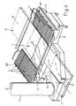
Fig. 3 is a perspective view of the recovery system; -
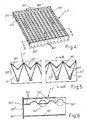
Fig. 4 is a perspective view of one of the corrugated filter grids mounted in an inclined position on the suction intakes operating inside the spraying machine; -
Fig. 5 shows other details of the filter grid ofFigure 4 , in a cross section taken along the line V-V; -
Fig. 6 shows other details of the filter grid ofFigure 5 , in a longitudinal section taken along the line VI-VI. - In
Figures 1 and2 , thenumber 1 indicates the chamber of the spraying machine, which has a knownupper part 101 designed to allow the forced and controllable introduction of filtered air from the external environment, and in which the opposite ends of the lower part haveapertures end return rollers horizontal belt conveyor 4 which moves, for example, in the direction of the arrow F. The articles P to be painted are supplied to theconveyor 4 from an external conveyor T1, while a downstream external conveyor T2 collects and removes the articles which while travelling along the upper branch of theconveyor 4 are painted by spraying elements P1 and P2, each having six or four guns for example, which operate inside thechamber 1 and which are automatically controlled by known systems. Known means 5 operate on the lower branch of thebelt conveyor 4, these means removing the paint not used on the painted articles from the said belt, enabling this paint to be recovered and allowing the said belt to return in a clean state to form the active upper branch. -
Suction intakes 6, 6', made for example with metal frameworks, are provided in thechamber 1 at the sides of theconveyor 4, these intakes essentially having the same length as thechamber 1, being of rectangular shape and characterized by a transverse inclination which makes them converge downwards and towards the longitudinal median axis of the said conveyor. Filter grids 7, 7' of rectangular shape, positioned adjacent to each other in a sufficient number to cover the whole extension of the said intakes, are mounted removably on theintakes 6, 6'. The details inFigures 4, 5 and 6 show how each grid 7, 7' is formed by alower cover 107 of corrugated stainless steel sheet or other suitable material, the corrugations having an internal angle of approximately 40º and oriented with their longitudinal axes orthogonal to the longitudinal axis of theconveyor 1 and having their ends fixed toflat cross-pieces 207, 207', also made from stainless steel, having heights greater than that of the corrugated profile of thesheet 107 in such a way that they project for a suitable distance both above and below the saidsheet 107. Anothercorrugated sheet 307, also made from stainless steel, rests on top of thesheet 107, the corrugations of this upper sheet having the same pitch as those of the lower sheet but a larger angle, for example approximately 90º, in such a way that they bear on the vertices of the corrugations of the said lower sheet and are partially inserted between them. Thesheet 307 is also held in the correct position by its ends which bear on thecross-pieces 207, 207' of the lower sheet which supports it, the whole being constructed in such a way that the two sheets can easily be detached from each other when necessary for the periodic rapid cleaning of the grids 7, 7'. Each grid 7, 7' bears on the longitudinal edges of anintake 6, 6' with itslower sheet 107 which has across-piece 407 fixed underneath it for bearing on the outer side of the highest edge of thesaid intake 6, 6', the whole being constructed in such a way that the said grids remain stably in the position in which theirupper cross-pieces 207, each provided in its median area with ahandle 507, are located outside the upper parts of the suction intakes, and their cross-pieces 207' are located outside the lower parts of the said intakes, each of the latter cross-pieces being located above theconveyor 4 and havingdischarge apertures 607 adjoining the lower vertices of thecorrugated sheets equidistant holes 707 over their whole extensions and in the mid-lines of the channels of theupper sheet 307, and with identical and equidistant holes 707' in the upper parts of the corrugations of thelower sheet 107, these holes being staggered with respect to each other as shown in detail inFigure 6 , in such a way that the flow of air sucked in by theintakes 6, 6' is forced to pass along a labyrinthine path through the holes of the grids 7, 7', so that it is made to contact the whole surface of the grids in question and to deposit the paint mist on these grids, both as a result of the surface contact and as a result of the collision which causes the droplets of paint to be deposited on thesheets conveyor 4 through theholes 607 and the cross-piece 207' which acts as a drip strip. In a variant embodiment which is not illustrated, at least thelower sheet 107 incorporated in the filter grid 7, 7' can be free of holes 707' in the portion which projects from the suction intakes and which is located on theconveyor 4 of the spraying machine. For additional assistance in preventing the soiling of the outer and lowest parts of the suction intakes or of the surfaces between these and theconveyor 4, thelower sheet 107 of each filter grid 7, 7' can be provided below with a cross-piece acting as a drip strip, which reproduces the corrugated profile and which projects downwards inside the suction intake, slightly in front of the lowest edge bearing on the intake. -
Figure 2 shows that thechamber 1 is provided, near the filter grids 7, 7', withhatches 201, 201' to provide access to these grids. At the end of the working day, when the machine is stopped, in order to prevent paint from dripping from the grids 7, 7' onto thestationary conveyor 1, the said hatches are opened and the grids 7, 7' are withdrawn by means of thehandles 507 and are positioned with their perforated end cross-pieces 207' inside theintakes 6, 6', as illustrated in broken lines, in such a way that the residual paint on the said grids drips into these intakes, to prevent excessive accumulation of paint on theconveyor 4 when it is stationary. -
Figure 2 also shows howfilters 9, 9', formed for example from panels with fibres of synthetic material or chips of metal or other suitable material, are housed removably and in an inclined arrangement with their ends supported inseats 8, 8' located under the longitudinal sides of the said intakes, at least in the upper parts of thesuction intakes 6, 6', these filters additionally contributing to the capture of droplets of paint contained in the mist sucked from thechamber 1. Clearly, other filters, whether self-cleaning or not, again preferably in an inclined position and removable to allow periodic cleaning, can be housed in thesuction intakes 6, 6'. - The suction intakes are made in the form of hoppers, in such a way that all the paint falling onto their inner surfaces flows downwards by gravity.
Figures 1 ,2 and3 show that the lower ends of thesuction intakes 6, 6' are connected to each other by aboxlike collector 10 of predominantly horizontal extension, made for example with a metal framework and positioned transversely under theconveyor 4 of the spraying machine. Thelower wall 110 of thecollector 10 is made in such a way that it converges towards a central lower area connected by asuitable discharge tube 111 to atank 11 into which all the paint falling from the suction intakes and from the self-cleaning filters located therein flows by gravity, this tank being made removable for period emptying and/or being provided with suction means for the automatic extraction of the collected product. - The
collector 10 is provided in the middle of its side with anaperture 12, of rectangular section for example, connected to aduct 13 which is also boxlike and has a predominantly horizontal extension, made for example with a metal framework, and which in plan view is L-shaped so that its end opposite to that connected to theaperture 12 is positioned laterally with respect to the conveyor T1 of the spraying machine, for connection to the lower end of anascending duct 14, having a suitable round section for example and of appropriate length, which terminates at its top in at least onebend 15 connected to the suction intake of acentrifugal fan 16 of suitable capacity, positioned with its axis horizontal or vertical, and having itsdischarge outlet 116 discharging directly into the atmosphere if required, outside the building in which the machine in question operates. Finally,Figure 1 also shows that the very small residual amount of paint drops suspended in the air reaching thefan 16 is made to precipitate in contact with the blades of this component and by centrifuging onto the fan casing, which can be covered internally with a porous surface to enhance the precipitation and retention of the product to be recovered, which flows into the lower part of the said casing into which opens adrainage duct 17 which discharges by gravity into theduct 13 or into another suitable position close to thecollecting tank 11. Thelower wall 113 of theduct 13 is also inclined progressively downwards towards thetank 11, in such a way that all the paint falling from this duct and from thesubsequent ducts - If required by the nature of the product to be recovered, the
duct 13 can contain filters of the self-cleaning or other type, in a cassette arrangement, in such a way that they can be pulled out when necessary for periodic cleaning, the whole being arranged in a way which can be readily understood and implemented by a person skilled in the art. In order to increase the purifying capacity of the system even further, all of its surfaces which are located at the points of deflection of the flow of sucked air and whose contact with the said flow tends to be greater than that of other surfaces, for example the part of the inner walls of thecollector 10 underneath theintakes 6, 6' (Fig. 2 ), the angled inclined wall of the duct 13 (Fig. 3 ), and the wall with greatest curvature of the bend 15 (Fig. 2 ), can be provided, for example, with porous finned elements and/or can be provided with other known means for the precipitation of the paint droplets carried by the air.
Claims (14)
- Self-cleaning system for dry recovery of processing mists in automatic machines for spraying UV-dried acrylic paints, of the type in which the chamber (1) in which the spray guns (P1, P2) operate is connected in its upper part to the atmosphere through a circuit for the admission of clean ambient air and in which, inside the said chamber (1), at the sides of the self-cleaning conveyor (4) for advancing the articles (P) to be painted, there are suction intakes (6, 6') connected to an external fan (16) of suitable capacity, with the interposition of suitable dry filter means, characterized in that the said suction intakes (6,6') are inclined transversely downwards towards the said conveyor (4) and are designed in such a way that filter grids (7, 7') with corrugated profiles can be positioned transversely on them, the grids (7,7') being adjacent to each other, in such a way as to cover the whole extension of the said intakes (6,6') the longitudinal axes of the corrugations being orientated orthogonally to the longitudinal axis of the conveyor (4) on which the lower ends of the grids (7,7') are positioned, in such a way that the paint retained by the said grids (7,7'), which are provided with suitably staggered holes (707, 707') for the passage of air, drips onto the said conveyor (4) which carries it away towards cleaning and recovery means (5) associated with the conveyor (4).
- System according to Claim 1, in which the said filter grids (7, 7') are made from stainless steel or other suitable material.
- System according to Claim 1, in which each filter grid (7, 7') is provided on its underside with a cross-piece or other projecting means (407), which bears on the outside of the higher longitudinal side of the suction intake (6, 6').
- System according to Claim 1, in which each filter grid (7, 7') is provided with at least one handle (507) on its upper side, in such a way that it can be easily handled by the operators at various times, including times when the spraying machine is not operating and the said grids (7,7') are withdrawn and placed with their lower ends inside the suction intakes (6, 6'), the chamber (1) of the said machine being provided for this purpose with lateral hatches (201, 201') through which the said grids (7, 7') can be accessed.
- System according to Claim 1, in which each filter grid (7, 7') comprises a lower corrugated sheet (107) fixed at its ends to flat cross-pieces (207, 207') whose heights are greater than that of the corrugated profile of the lower corrugated sheet (107), in such a way that they project by a suitable distance above and below this sheet (107), so that a second, upper, corrugated sheet (307) can be retained by bearing on the cross-pieces (207,207') and is therefore removable when necessary, the corrugations of the second corrugated sheet (307) having a larger angle than the corrugations of the lower corrugated sheet (107), in such a way that they are suitably spaced apart from them, the cross-piece (207') which is lower when the filter grid (7,7') is positioned on the suction intakes (6,6') being provided with discharge holes (607) adjoining the lower vertices of the two corrugated sheets (107,307), the upper sheet (307) being provided with equidistant holes (707) in the lower vertices of its corrugations, while the lower sheet (107) is provided with identical and equidistant holes (707') in the upper parts of the flat faces of its corrugation, these holes being staggered with respect to the holes (707) in the upper sheet (309), in such a way that the flow of air sucked in by the intakes (6, 6') is forced to follow a labyrinthine path in passing through the perforated corrugated sheets (107,307) of the filter grids (7, 7'), to contact the whole surface of these sheets and to deposit the paint droplets on them, both as a result of the surface contact and as a result of precipitation, the paint collected by the two corrugated sheets (107,307) of the filter grids (7,7') being made to flow by gravity along the corrugations of these sheets (107,307) and fall onto the conveyor (4) through the holes (607) of the lower end cross-piece (207') which also acts as a drip strip. '
- System according to Claim 5, in which the two corrugated sheets (107, 307) making up each filter grid (7, 7') have identical corrugation pitches.
- System according to Claim 5, in which the lower corrugated sheet (107) of each filter grid (7, 7') has corrugations with an angle of less than 90°, for example approximately 40°, while the upper corrugated sheet (307') of the said grids (7,7') has corrugations with an angle of approximately 90°-.
- System according to claim 5, in which at least the lower sheet (107) of the filter grid (77') can be free of holes in the portion which projects from the suction intakes (6,6') and which is located on the conveyor (4) of the spraying machine.
- System according to claim 5, in which the lower sheet (107) of each filter grid (7, 7') can be provided in its lower part with a cross-piece which reproduces its corrugated profile and which projects downwards into the suction intake (6,6'), before the lowest edge which bears on the said intake (6,6') this cross-piece acting as a drip strip.
- System according to claim 1, in which at least the upper parts of the suction intakes (6, 6') contain removable and preferably inclined filters of the self-cleaning or other type (9, 9'), consisting for example of panels made with fibres of synthetic material or metal chips or other suitable material, through which the flow of air passes, and which also contribute to the capture of the paint droplets contained in the mists sucked from the spraying chamber (1).
- System according to claim 10, in which the lower ends of the suction intakes (6, 6') are connected together by a boxlike collector (10) having a predominantly horizontal extension, positioned transversely and under the conveyor (4) of the spraying machine, the lower wall (110) of the collector (10) being such that it converges towards a central lower area in which is located a tank (11), into which all the paint falling from the suction intakes (6,6') and from the filters (9,9') located therein tends to flow by gravity, and which can be designed to be removable for periodic emptying or which can be provided with suction means for automatic extraction of the collected product, the intermediate part of the said collector (10) being made with a lateral aperture (12) connected to a duct (13), also boxlike and having a predominantly horizontal extension, which in plan view appears L-shaped so that its end opposite that connected to the said aperture (12) is positioned at the side of the external conveyor (T1) of the spraying machine, for connection to the lower end of an ascending duct (14), also of appropriate length, which preferably terminates at its top in at least one bend (15) connected to the suction intake of a fan (16) which discharges into the atmosphere, the lower wall of the said box like duct (13) being made inclined with a progressive descent towards said tank (11), in such a way that all the paint flowing from this boxlike duct (13) and from the downstream ascending duct (14) and the bend (15) flows into the said collecting tank (11).
- System according to Claim 11, in which the said fan (16) is of the centrifugal type and is designed in any suitable way to recover the residual paint droplets contained in the air by precipitation on the blades of the fan and by centrifugal force, the casing of this component being covered or internally structured with a porous surface if necessary, to enhance the precipitation and retention of the paint, and being provided in its lower part with a trap in which the recovered paint is collected and which opens into a drainage duct (17) which discharges by gravity into any lower part of the system, near the said collecting tank (11).
- System according to claim 1, in which, if required by the nature of the paint to be recovered, self-cleaning filters can be positioned in a cassette arrangement in the accessible horizontal part of the said system, in such a way that the filters can be withdrawn when necessary for periodic cleaning.
- System according to claim 1, in which the inner surfaces of the system which are located at a point of deflection of the flow of air sucked in and which tend to be in contact with the said flow to a greater extent than other surfaces, can be provided for example with finned porous inserts or other known means for precipitating the paint particles carried by the air.
Applications Claiming Priority (2)
| Application Number | Priority Date | Filing Date | Title |
|---|---|---|---|
| IT000032U ITBO20030032U1 (en) | 2003-03-28 | 2003-03-28 | SELF-CLEANING SYSTEM FOR DRY RECOVERY OF WORKING MIST AND AUTOMATIC MACHINES FOR SPRAYING ACRYLIC PAINTS WITH UV DRYING OR OTHER PRODUCTS WHICH REQUIRE ANALOGUE NEEDS |
| ITBO20030032U | 2003-03-28 |
Publications (3)
| Publication Number | Publication Date |
|---|---|
| EP1462182A2 EP1462182A2 (en) | 2004-09-29 |
| EP1462182A3 EP1462182A3 (en) | 2007-09-12 |
| EP1462182B1 true EP1462182B1 (en) | 2009-02-11 |
Family
ID=32800650
Family Applications (1)
| Application Number | Title | Priority Date | Filing Date |
|---|---|---|---|
| EP04006655A Expired - Lifetime EP1462182B1 (en) | 2003-03-28 | 2004-03-19 | Self-cleaning system for dry recovery of processing mists in automatic machines for spraying paints |
Country Status (5)
| Country | Link |
|---|---|
| US (1) | US6969428B2 (en) |
| EP (1) | EP1462182B1 (en) |
| DE (1) | DE602004019353D1 (en) |
| ES (1) | ES2322053T3 (en) |
| IT (1) | ITBO20030032U1 (en) |
Cited By (1)
| Publication number | Priority date | Publication date | Assignee | Title |
|---|---|---|---|---|
| CN103203300A (en) * | 2013-04-11 | 2013-07-17 | 机科发展科技股份有限公司 | Automatic oiling device |
Families Citing this family (27)
| Publication number | Priority date | Publication date | Assignee | Title |
|---|---|---|---|---|
| DE102005013709B4 (en) | 2005-03-24 | 2023-02-16 | Dürr Systems Ag | Device for separating wet paint overspray and system for painting objects |
| US8683940B2 (en) * | 2006-10-13 | 2014-04-01 | Lg Chem, Ltd. | Apparatus for coating a profile surface, and coating method thereof |
| CN100441314C (en) * | 2006-12-11 | 2008-12-10 | 俞银德 | A spray booth for purifying paint mist |
| CN100441315C (en) * | 2006-12-11 | 2008-12-10 | 俞银德 | A spray booth for purifying paint mist |
| US9545645B2 (en) * | 2009-05-07 | 2017-01-17 | Michael C. Thomason | Paint spray booth |
| DE102011016289A1 (en) * | 2011-04-07 | 2012-10-11 | Cft Gmbh Compact Filter Technic | Wet scrubbers with reduced energy requirement requiring compact demister |
| DE102011102617A1 (en) * | 2011-05-27 | 2012-11-29 | Berkmann NT Ingenieurbüro | filter system |
| ITBO20120077A1 (en) * | 2012-02-20 | 2013-08-21 | Cefla Coop | METHOD AND EQUIPMENT FOR PAINT FINISH OF PREVALENT EXTENSION OF FLAT PAINT |
| FI125920B (en) * | 2013-09-09 | 2016-04-15 | Beneq Oy | Method of coating substrates |
| CN106733377A (en) * | 2016-12-29 | 2017-05-31 | 天津浩华民生科技发展有限公司 | A kind of floor processes special dries energy saving and environment friendly paint spraying machine |
| CN107857088A (en) * | 2017-11-14 | 2018-03-30 | 广东顺德迪峰机械有限公司 | A kind of flush coater no pollution Transmission system |
| MX2020006178A (en) | 2017-12-14 | 2020-09-03 | Giffin Inc | Spray booth with carousel dry filter module. |
| CN108311315B (en) * | 2018-03-29 | 2021-04-27 | 烟台南山学院 | Novel electromechanical device for paint spraying processing |
| LU101440B1 (en) | 2019-10-17 | 2021-04-19 | Ucube Lab Sa | Air filter for a painting booth used for spray coating |
| CN112974073B (en) * | 2019-12-13 | 2022-12-23 | 四川欧铂亚门业有限公司 | Wood door paint spraying device and paint spraying method |
| CN111760708B (en) * | 2020-07-14 | 2021-12-14 | 湖州忻宝自动化科技有限公司 | Auxiliary device for color paint spraying with collecting function |
| CN112058568B (en) * | 2020-08-24 | 2021-12-14 | 湖北世亮汽车零部件有限公司 | Bumper shell finish paint spraying device capable of detecting surface smoothness of bumper |
| US11745206B2 (en) * | 2020-08-24 | 2023-09-05 | Columbus Industries, Inc. | Filtering apparatus with at least one filter unit |
| CN112221791A (en) * | 2020-09-29 | 2021-01-15 | 杭州芥蒂电子商务有限公司 | Intelligence automobile wheel hub sprays paint and uses lacquer liquid recovery unit |
| CN112619965A (en) * | 2020-12-21 | 2021-04-09 | 天长市市政建筑有限责任公司 | Two-sided structure of spraying paint of building decoration panel |
| CN113019787B (en) * | 2021-02-03 | 2022-06-07 | 大唐依兰风力发电有限公司 | Automatic spraying device for large wind power |
| CN113909037B (en) * | 2021-08-20 | 2025-03-11 | 泰信电机(苏州)有限公司 | A paint spraying device with material recovery function for the outer surface of a motor housing |
| CN113828458A (en) * | 2021-09-10 | 2021-12-24 | 罗慧敏 | New energy automobile accessory paint spraying apparatus |
| CN115069474B (en) * | 2022-07-23 | 2022-10-21 | 山东信息职业技术学院 | Artificial intelligence-based spraying device |
| CN115555207B (en) * | 2022-10-28 | 2023-05-05 | 广东芯乐光光电科技有限公司 | Mini-LED dispensing system and dispensing method |
| CN116764862A (en) * | 2023-06-13 | 2023-09-19 | 湖南永盛液压科技有限公司 | An environmentally friendly spraying workshop |
| CN117483153A (en) * | 2023-11-01 | 2024-02-02 | 上海通周机械设备工程有限公司 | A paint mist recovery system |
Family Cites Families (10)
| Publication number | Priority date | Publication date | Assignee | Title |
|---|---|---|---|---|
| GB166677A (en) * | 1920-04-17 | 1921-07-18 | Heenan & Froude Ltd | Improvements in moisture eliminators |
| FR2114132A5 (en) * | 1970-11-17 | 1972-06-30 | Tunzini Ameliorair Sa | |
| US4888200A (en) * | 1988-04-21 | 1989-12-19 | W. R. Grace & Co.,-Conn. | Process and machine for electrostatic coating |
| DE59007776D1 (en) * | 1989-06-16 | 1995-01-05 | Farb Tec Beschichtung | CAB FOR SPRAY COATING ITEMS WITH POWDERED COATING MATERIAL. |
| DE4425655A1 (en) * | 1994-07-20 | 1996-01-25 | Lucon Dipl Ing Juergen Lutterm | Device for the electrostatic spray coating of workpieces |
| FR2728802B1 (en) * | 1994-12-28 | 1997-03-21 | Lucas Sa G | FILTER FOR PAINT BOOTHS |
| DK0728530T3 (en) * | 1995-02-24 | 2000-12-11 | Michael Eder | Device for wet varnish spray painting of objects |
| EP0849001A1 (en) * | 1996-12-20 | 1998-06-24 | Robert sen. Wälti | Spray booth and air circulation system for a workspace |
| DE59907933D1 (en) * | 1999-02-12 | 2004-01-15 | Venjakob Maschinenb Gmbh & Co | Paint sprayer |
| US6585793B2 (en) * | 2000-12-29 | 2003-07-01 | Andreae Filters, Inc. | Filter apparatus and methods |
-
2003
- 2003-03-28 IT IT000032U patent/ITBO20030032U1/en unknown
-
2004
- 2004-03-19 EP EP04006655A patent/EP1462182B1/en not_active Expired - Lifetime
- 2004-03-19 DE DE602004019353T patent/DE602004019353D1/en not_active Expired - Lifetime
- 2004-03-19 ES ES04006655T patent/ES2322053T3/en not_active Expired - Lifetime
- 2004-03-25 US US10/808,419 patent/US6969428B2/en not_active Expired - Lifetime
Cited By (2)
| Publication number | Priority date | Publication date | Assignee | Title |
|---|---|---|---|---|
| CN103203300A (en) * | 2013-04-11 | 2013-07-17 | 机科发展科技股份有限公司 | Automatic oiling device |
| CN103203300B (en) * | 2013-04-11 | 2016-04-20 | 机科发展科技股份有限公司 | A kind of automatic oiling device |
Also Published As
| Publication number | Publication date |
|---|---|
| ES2322053T3 (en) | 2009-06-16 |
| ITBO20030032U1 (en) | 2004-09-29 |
| EP1462182A3 (en) | 2007-09-12 |
| US6969428B2 (en) | 2005-11-29 |
| EP1462182A2 (en) | 2004-09-29 |
| DE602004019353D1 (en) | 2009-03-26 |
| US20040187774A1 (en) | 2004-09-30 |
Similar Documents
| Publication | Publication Date | Title |
|---|---|---|
| US6969428B2 (en) | Self-cleaning system for dry recovery of processing mists in automatic machines for spraying paints | |
| US7014556B2 (en) | Powder coating systems | |
| JP5662473B2 (en) | Filter device, separation device and method for separating paint spray splash | |
| DE1652414B2 (en) | SYSTEM FOR PAINT SPRAYING, WITH A PAINT SPRAY CABIN WITH AIR-FLOWING FROM TOP TO BOTTOM | |
| US4440554A (en) | Gas scrubbing device | |
| CN113924170B (en) | Equipment for applying paint and method for cleaning same | |
| US5135550A (en) | Recirculating water washer means and method | |
| JP5422814B2 (en) | Paint collection system | |
| JPH0445565B2 (en) | ||
| US5074238A (en) | Production line paint spray booth with dual slots | |
| US11633752B2 (en) | Scrubber unit for a paint booth | |
| US4601236A (en) | Pump-less paint spray booth | |
| EP2236186B1 (en) | Baffle system for separating liquid from a gas stream | |
| EP1958703B1 (en) | Cleaning the interior of a powder spray booth by pulsating air flow | |
| EP2030696A1 (en) | Automatic painting plant for products of various kind | |
| JP6920672B1 (en) | Liquid collecting member for gas purifier and gas purifier | |
| CN221471302U (en) | Water mist cleaning machine | |
| DE1652414C3 (en) | System for paint spraying, with a paint spray booth through which air flows from top to bottom | |
| GB2040721A (en) | Spray booth with means for reclaiming excess spray | |
| WO1997005941A1 (en) | Device for separating fumes, oil droplets and/or dust from a stream of air | |
| GB2081601A (en) | Spraybooth |
Legal Events
| Date | Code | Title | Description |
|---|---|---|---|
| PUAI | Public reference made under article 153(3) epc to a published international application that has entered the european phase |
Free format text: ORIGINAL CODE: 0009012 |
|
| AK | Designated contracting states |
Kind code of ref document: A2 Designated state(s): AT BE BG CH CY CZ DE DK EE ES FI FR GB GR HU IE IT LI LU MC NL PL PT RO SE SI SK TR |
|
| AX | Request for extension of the european patent |
Extension state: AL LT LV MK |
|
| PUAL | Search report despatched |
Free format text: ORIGINAL CODE: 0009013 |
|
| AK | Designated contracting states |
Kind code of ref document: A3 Designated state(s): AT BE BG CH CY CZ DE DK EE ES FI FR GB GR HU IE IT LI LU MC NL PL PT RO SE SI SK TR |
|
| AX | Request for extension of the european patent |
Extension state: AL LT LV MK |
|
| 17P | Request for examination filed |
Effective date: 20080310 |
|
| AKX | Designation fees paid |
Designated state(s): DE DK ES IT SE |
|
| RAP1 | Party data changed (applicant data changed or rights of an application transferred) |
Owner name: CEFLA SOCIETA' COOPERATIVA |
|
| GRAP | Despatch of communication of intention to grant a patent |
Free format text: ORIGINAL CODE: EPIDOSNIGR1 |
|
| GRAS | Grant fee paid |
Free format text: ORIGINAL CODE: EPIDOSNIGR3 |
|
| GRAA | (expected) grant |
Free format text: ORIGINAL CODE: 0009210 |
|
| AK | Designated contracting states |
Kind code of ref document: B1 Designated state(s): DE DK ES IT SE |
|
| REF | Corresponds to: |
Ref document number: 602004019353 Country of ref document: DE Date of ref document: 20090326 Kind code of ref document: P |
|
| PGFP | Annual fee paid to national office [announced via postgrant information from national office to epo] |
Ref country code: DK Payment date: 20090326 Year of fee payment: 6 |
|
| REG | Reference to a national code |
Ref country code: ES Ref legal event code: FG2A Ref document number: 2322053 Country of ref document: ES Kind code of ref document: T3 |
|
| PG25 | Lapsed in a contracting state [announced via postgrant information from national office to epo] |
Ref country code: SE Free format text: LAPSE BECAUSE OF FAILURE TO SUBMIT A TRANSLATION OF THE DESCRIPTION OR TO PAY THE FEE WITHIN THE PRESCRIBED TIME-LIMIT Effective date: 20090511 |
|
| PG25 | Lapsed in a contracting state [announced via postgrant information from national office to epo] |
Ref country code: DK Free format text: LAPSE BECAUSE OF NON-PAYMENT OF DUE FEES Effective date: 20090211 |
|
| PLBE | No opposition filed within time limit |
Free format text: ORIGINAL CODE: 0009261 |
|
| STAA | Information on the status of an ep patent application or granted ep patent |
Free format text: STATUS: NO OPPOSITION FILED WITHIN TIME LIMIT |
|
| 26N | No opposition filed |
Effective date: 20091112 |
|
| REG | Reference to a national code |
Ref country code: DE Ref legal event code: R079 Ref document number: 602004019353 Country of ref document: DE Free format text: PREVIOUS MAIN CLASS: B05B0015120000 Ipc: B05B0016000000 |
|
| PGFP | Annual fee paid to national office [announced via postgrant information from national office to epo] |
Ref country code: IT Payment date: 20230221 Year of fee payment: 20 Ref country code: DE Payment date: 20230221 Year of fee payment: 20 |
|
| PGFP | Annual fee paid to national office [announced via postgrant information from national office to epo] |
Ref country code: ES Payment date: 20230403 Year of fee payment: 20 |
|
| REG | Reference to a national code |
Ref country code: DE Ref legal event code: R071 Ref document number: 602004019353 Country of ref document: DE |
|
| REG | Reference to a national code |
Ref country code: ES Ref legal event code: FD2A Effective date: 20240402 |
|
| PG25 | Lapsed in a contracting state [announced via postgrant information from national office to epo] |
Ref country code: ES Free format text: LAPSE BECAUSE OF EXPIRATION OF PROTECTION Effective date: 20240320 |
|
| PG25 | Lapsed in a contracting state [announced via postgrant information from national office to epo] |
Ref country code: ES Free format text: LAPSE BECAUSE OF EXPIRATION OF PROTECTION Effective date: 20240320 |