EP1462001B1 - Pest control device - Google Patents
Pest control device Download PDFInfo
- Publication number
- EP1462001B1 EP1462001B1 EP20040251679 EP04251679A EP1462001B1 EP 1462001 B1 EP1462001 B1 EP 1462001B1 EP 20040251679 EP20040251679 EP 20040251679 EP 04251679 A EP04251679 A EP 04251679A EP 1462001 B1 EP1462001 B1 EP 1462001B1
- Authority
- EP
- European Patent Office
- Prior art keywords
- container
- aggregation base
- station
- termites
- aggregation
- Prior art date
- Legal status (The legal status is an assumption and is not a legal conclusion. Google has not performed a legal analysis and makes no representation as to the accuracy of the status listed.)
- Expired - Lifetime
Links
- 241000607479 Yersinia pestis Species 0.000 title description 15
- 230000002776 aggregation Effects 0.000 claims description 115
- 238000004220 aggregation Methods 0.000 claims description 115
- 241000256602 Isoptera Species 0.000 claims description 100
- 239000011800 void material Substances 0.000 claims description 15
- 241001509990 Rhinotermitidae Species 0.000 claims description 3
- 239000002023 wood Substances 0.000 claims description 3
- 238000012544 monitoring process Methods 0.000 description 52
- 239000000463 material Substances 0.000 description 16
- 238000000034 method Methods 0.000 description 7
- 239000002689 soil Substances 0.000 description 7
- 231100000331 toxic Toxicity 0.000 description 7
- 231100000167 toxic agent Toxicity 0.000 description 7
- 230000002588 toxic effect Effects 0.000 description 7
- 239000003440 toxic substance Substances 0.000 description 7
- 238000007689 inspection Methods 0.000 description 6
- 206010061217 Infestation Diseases 0.000 description 4
- 239000000203 mixture Substances 0.000 description 4
- 231100000252 nontoxic Toxicity 0.000 description 4
- 230000003000 nontoxic effect Effects 0.000 description 4
- 239000000575 pesticide Substances 0.000 description 4
- 230000007704 transition Effects 0.000 description 4
- 230000004931 aggregating effect Effects 0.000 description 3
- 229920002678 cellulose Polymers 0.000 description 3
- 239000001913 cellulose Substances 0.000 description 3
- 238000010276 construction Methods 0.000 description 3
- 239000003826 tablet Substances 0.000 description 3
- 241000238631 Hexapoda Species 0.000 description 2
- 241000466325 Trinervitermes biformis Species 0.000 description 2
- 230000000295 complement effect Effects 0.000 description 2
- 239000007891 compressed tablet Substances 0.000 description 2
- 238000013461 design Methods 0.000 description 2
- 238000001514 detection method Methods 0.000 description 2
- 230000002431 foraging effect Effects 0.000 description 2
- 238000006467 substitution reaction Methods 0.000 description 2
- XLYOFNOQVPJJNP-UHFFFAOYSA-N water Substances O XLYOFNOQVPJJNP-UHFFFAOYSA-N 0.000 description 2
- 241000257303 Hymenoptera Species 0.000 description 1
- NIXOWILDQLNWCW-UHFFFAOYSA-N acrylic acid group Chemical group C(C=C)(=O)O NIXOWILDQLNWCW-UHFFFAOYSA-N 0.000 description 1
- 238000013459 approach Methods 0.000 description 1
- 239000010426 asphalt Substances 0.000 description 1
- 239000011111 cardboard Substances 0.000 description 1
- 238000004891 communication Methods 0.000 description 1
- 230000007797 corrosion Effects 0.000 description 1
- 238000005260 corrosion Methods 0.000 description 1
- 230000006866 deterioration Effects 0.000 description 1
- 230000000694 effects Effects 0.000 description 1
- 230000008030 elimination Effects 0.000 description 1
- 238000003379 elimination reaction Methods 0.000 description 1
- 239000006261 foam material Substances 0.000 description 1
- 239000004459 forage Substances 0.000 description 1
- 239000003630 growth substance Substances 0.000 description 1
- 239000003112 inhibitor Substances 0.000 description 1
- 238000009434 installation Methods 0.000 description 1
- 230000001788 irregular Effects 0.000 description 1
- 230000002503 metabolic effect Effects 0.000 description 1
- 235000016709 nutrition Nutrition 0.000 description 1
- 230000035764 nutrition Effects 0.000 description 1
- 239000000123 paper Substances 0.000 description 1
- 244000052769 pathogen Species 0.000 description 1
- 230000001717 pathogenic effect Effects 0.000 description 1
- 239000004576 sand Substances 0.000 description 1
- 239000000126 substance Substances 0.000 description 1
- 230000001629 suppression Effects 0.000 description 1
- 239000003053 toxin Substances 0.000 description 1
- 231100000765 toxin Toxicity 0.000 description 1
- 238000011179 visual inspection Methods 0.000 description 1
- 230000003442 weekly effect Effects 0.000 description 1
Images


Classifications
-
- A—HUMAN NECESSITIES
- A01—AGRICULTURE; FORESTRY; ANIMAL HUSBANDRY; HUNTING; TRAPPING; FISHING
- A01M—CATCHING, TRAPPING OR SCARING OF ANIMALS; APPARATUS FOR THE DESTRUCTION OF NOXIOUS ANIMALS OR NOXIOUS PLANTS
- A01M1/00—Stationary means for catching or killing insects
- A01M1/20—Poisoning, narcotising, or burning insects
- A01M1/2005—Poisoning insects using bait stations
- A01M1/2011—Poisoning insects using bait stations for crawling insects
-
- A—HUMAN NECESSITIES
- A01—AGRICULTURE; FORESTRY; ANIMAL HUSBANDRY; HUNTING; TRAPPING; FISHING
- A01M—CATCHING, TRAPPING OR SCARING OF ANIMALS; APPARATUS FOR THE DESTRUCTION OF NOXIOUS ANIMALS OR NOXIOUS PLANTS
- A01M1/00—Stationary means for catching or killing insects
- A01M1/02—Stationary means for catching or killing insects with devices or substances, e.g. food, pheronones attracting the insects
- A01M1/026—Stationary means for catching or killing insects with devices or substances, e.g. food, pheronones attracting the insects combined with devices for monitoring insect presence, e.g. termites
-
- A—HUMAN NECESSITIES
- A01—AGRICULTURE; FORESTRY; ANIMAL HUSBANDRY; HUNTING; TRAPPING; FISHING
- A01M—CATCHING, TRAPPING OR SCARING OF ANIMALS; APPARATUS FOR THE DESTRUCTION OF NOXIOUS ANIMALS OR NOXIOUS PLANTS
- A01M2200/00—Kind of animal
- A01M2200/01—Insects
- A01M2200/011—Crawling insects
Landscapes
- Life Sciences & Earth Sciences (AREA)
- Pest Control & Pesticides (AREA)
- Engineering & Computer Science (AREA)
- Insects & Arthropods (AREA)
- Wood Science & Technology (AREA)
- Zoology (AREA)
- Environmental Sciences (AREA)
- Health & Medical Sciences (AREA)
- General Health & Medical Sciences (AREA)
- Toxicology (AREA)
- Catching Or Destruction (AREA)
Description
- This invention generally relates to a pest control device, and more particularly to a method and system for termite interception and baiting.
- Many pests, such as termites, are serious threats throughout much of the world to structures or other objects containing wood or other cellulose containing components because these pests consume cellulose for nutrition. Subterranean termites, which typically dwell in the soil, often form large colonies. Members of the colony forage for food and thus burrow galleries or passageways in the soil outwardly from the nest. Portions of the food located by the foraging termites are returned to the nest. Termites are also known to possess means for communicating the location of a food source to other termites within the colony.
- Many pest control devices are known and formed in a wide variety of configurations to monitor and eradicate the pests. One type of popular termite control device utilizes a monitoring food source made from a medium that is attractive to termites to encourage the termites to begin feeding from the device. The termites are then eliminated by providing a toxicant-containing bait placed at the feeding point in the termite control device. Perhaps most important, termite baiting results in the elimination or suppression of the entire termite colony, not just the members of the colony that reach the station site, because the toxicant-containing bait is brought to the nest with the returning termites. Because a termite bait must be consumed by termites in order to be effective, a technique must be developed to consistently and repeatedly make the bait available for consumption by members of a termite colony at a fixed point over a long enough period of time for the bait to have the intended toxic effect on the colony.
- Typically, the toxic termite bait is applied only after contact has been established with a termite colony and termites are feeding from the station. Reasons for this include minimization of the amount of bait used, potential deterioration of bait if it is left in place for long periods of time in anticipation of prospective termite attack, minimization of the potential for unintended exposure of children and pets to the bait, etc. Therefore, it is preferable to first detect termites at the bait holder with a nontoxic medium while monitoring the site. After termites are detected, the toxic bait is applied to the bait holder.
- Such systems must be inspected periodically, such as every one to three months, to determine if termites are active within the bait holder. However, to accomplish this, a baiting system must deal with several issues that left unresolved, make a baiting method and/or system less likely to succeed. For example, when inspecting the monitoring medium or the bait within the bait holder or when adding or replacing the toxic bait, the feeding site is typically disturbed. This may cause the termites to abandon the bait holder altogether.
-
US6016625 discloses an apparatus and method for monitoring and/or controlling pests, particularly termites. The apparatus employ one or more extractor means for selectively moving termite monitoring and/or termite baiting devices. Stations used for the monitoring or control of termites are comprised of a housing that contains combinations of stacks of termites monitoring and/or termite baiting devices and one or more extractor means for selectively moving the monitoring and/or baiting devices. -
US2002/0023382 discloses a housing provided for a station or device adapted for monitoring and/or controlling termites or other insects. The station is adapted to be situated in or on soil or sand. The housing contains a substance attractive for termite exploration and/or termite feeding and comprises at least one or more and at least one surface which defines at least one path attractive to termites such as a groove or a channel. - Among the several objects and features of the present invention may be noted the provision of such a device that permits termite detection and baiting in a manner where the transition of feeding termites from nontoxic to toxic bait is effected with minimal, if any, disturbance of the, nontoxic bait feeding site; the provision of such a device that permits efficient removal and installation of a pest control toxin; and the provision of such a device that is simple to use.
- The invention relates to an apparatus for detecting and controlling subterranean termites, said apparatus comprising:
- a station including annular side walls and a bottom, said station being at least partially receivable within a subterranean cavity and having at least one opening therein to provide access by said termites to an interior volume of said station;
- an aggregation base attractive to said termites received within said interior volume of said station, said aggregation base being generally cylindrically shaped and including a generally cylindrical outer surface facing the side wall of the station, said aggregation base including at least one void for forming an aggregation site for said termites, and wherein said aggregation base further comprises at least one channel passing through the aggregation base from the cylindrical outer surface and leading inward to said void; and
- a replaceable container received within said interior volume of said station and positioned adjacent said aggregation base, said container having at least one opening in a surface thereof facing the aggregation base to permit the passage of termites from the aggregation base to an interior chamber of said container, and said container being sized and shaped such that the container may be removed from the station without substantially disturbing the aggregation base, thereby preserving any aggregation site formed by the termites within the void of the aggregation base.
- Other objects and features will be in part apparent and in part pointed out hereinafter.
-
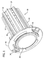
Fig. 1 is a perspective of an embodiment of the pest control device of the present invention; -
Fig. 2 is an exploded perspective of the pest control device ofFig. 1 ; -
Fig. 3 is a perspective of an aggregation base used with the pest control device ofFig. 1 ; -
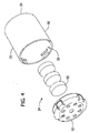
Fig. 4 is an exploded perspective of a container used in the pest control device ofFig. 1 ; -
Fig. 5 is an exploded perspective of a bait container similar in construction to the monitoring container ofFig. 4 with a bait placed therein; -
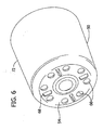
Fig. 6 is a perspective of a cup portion of the container ofFig. 4 ; -
Fig. 7 is another perspective of the cup ofFig. 4 ; and -
Fig. 8 perspective of a lid portion of the container ofFig. 4 . - Corresponding reference characters indicate corresponding parts throughout the several views of the drawings.
-
Figs. 1 and2 illustrate a pest monitoring and control station, generally illustrated byreference numeral 10, in accordance with one embodiment of the present invention. Although the illustrated embodiment is particularly suitable for monitoring and controlling termites, it is contemplated that the invention may be used to monitor and control other pests, such as ants. As best illustrated in the exploded view ofFig. 2 , thestation 10 includes a substantiallyhollow housing 12 having anannular side wall 14, atop surface 16 and abottom surface 18 defining aninterior volume 20. A portion of thetop surface 16 of thehousing 12 is open exposing theinterior volume 20. Thestation 10 receives one or more of anaggregation base 22, amonitoring container 24 and/or a bait container 25 (not shown but described below with reference toFig. 5 ) within theinterior volume 20 of thehousing 12. - A
cap 28 is removably received on thetop surface 16 to close thehousing 12. Thecap 28 is removably secured to thetop surface 16 of thehousing 12. In one embodiment, thecap 28 has a pair oftabs 30 that extend intoslots 32 in thetop surface 16 of thehousing 12. Thecap 28 is then rotated either counter clockwise or clockwise to engage thecap 28. The tabs include achamfer 34 along a leadingedge 36 of thetab 30. As thecap 28 rotates into position, thechamfer 34 helps guide thetab 30 into position within theslot 32. Other suitable means for securing thecap 28 to thetop surface 16 may be used. - Preferably, the
housing 12 is formed from a durable, corrosion resistant material, as for example, an acrylic or high strength plastic.According to the invention, the housing has a generally cylindrical shape. Preferably, thestation 10 has a maximum height of less than about 18 inches (457 mm) and maximum diameter or width of less than about 12 inches (305 mm), and more preferably the station has a maximum height of less than about 9 inches (229 mm) and maximum width of less than about 4 inches (102 mm). - The
station 10 includes at least one opening 37 passing through theside wall 14 to permit the ingress and egress of termites into and out of theinterior volume 20 of station. Preferably, theside wall 14 has several verticalelongated openings 37 therein extending substantially the entire length of the side wall. As used herewith, vertical is used in reference to the preferred orientation of thestation 10 with thetop surface 16 facing in an upward direction. It is contemplated however, that other shapes and orientations for the openings may be used. For example, the openings may be horizontal elongated openings, or may be circular openings randomly placed or formed in a repeating pattern. Additionally, there may beopenings 37 in thebottom surface 18 leading to theinterior volume 20. In an alternate version, theopenings 37 are formed only in alower portion 38 of theside wall 14 of thehousing 12 such that anupper portion 39 of theside wall 14 near thetop surface 16 of thehousing 12 is imperforate. - In use, the
station 10 is at least partially received within a cavity accessible to termites, while still being accessible above ground by a user. The cavity may be a subterranean cavity, or may be a cavity within a wall or other framework of a building or other above ground structure. The cavity may be formed in the soil, or the cavity may be formed in a paving material, such as concrete or asphalt, with soil beneath the paving material. Preferably, thestation 10 is substantially entirely received within the cavity such that only thetop surface 16 andcap 28 are accessible from above ground. However, in some situations, thestation 10 may be nearly entirely on top of the ground, such that the cavity is very shallow. - In one embodiment, as shown in
Fig. 2 , theaggregation base 22 is received within theinterior volume 20 of thehousing 12 such that it is positioned adjacent thelower portion 38 of theside wall 14 so that theelongate openings 37 expose theaggregation base 22 to the subterranean cavity. The monitoringcontainer 24 or thebait container 25 is then received within theinterior volume 20 of the housing so as to be received adjacent to theaggregation base 22. It is also contemplated that the aggregation base may be formed as a tube and thereplaceable monitoring container 24 orbait container 25 configured to be received within the hollow interior of the tube. - Alternately, the
aggregation base 22 is received directly within the cavity. For example, when theaggregation base 22 is to be used in a more durable environment where there is little possibility that sidewalls of the cavity will collapse around theaggregation base 22, such as, for example, in paving material, theaggregation base 22 can be placed directly into the cavity. The monitoringcontainer 24 or thebait container 25 then may be positioned in the cavity adjacent to, and preferably directly above, theaggregation base 22. In such an embodiment, there is no need for a station to receive theaggregation base 22 and thecontainers aggregation base 22 andcontainers aggregation base 22 is located in the cavity orstation 10 in a substantially stationary manner so that there is minimal disturbance to the aggregation site and the termites while thecontainers -
Fig. 3 illustrates an embodiment of theaggregation base 22. According to the invention , the aggregation base is formed in a generally cylindrical shape such that anouter surface 40 of the aggregation base faces the interior of thesidewall 14 of thestation 10 or cavity when placed in service. Other versions of the aggregation base may have different geometric shapes suitable for use depending on the cavity into which the base is received. In an embodiment of theaggregation base 22 to be received within theinterior volume 20 of thestation 10, it is preferable that theaggregation base 22 have a shape similar to the shape of thehousing 12 with a width slightly less than an inner width of thehousing 12 so that theaggregation base 22 may be removably received in a snug fitting relationship within thehousing 12. According to the invention, theaggregation base 22 has a void 42 substantially centrally located within theaggregation base 22 which is suitable for an aggregation site for termites. Theaggregation base 22 includeschannels 44 passing through theaggregation base 22 from theouter surface 40 inward to the void 42. Preferably, thechannels 44 guide the termites from theouter surface 40 to the aggregation site in thevoid 42 of theaggregation base 22. Preferably, theaggregation base 22 is made from a cellulosic material attractive to termites, such as wood. - Alternately, the
aggregation base 22 may be made of plastic or other suitable material and filled with cellulosic material, such as paper, cardboard, compressed tablets, or other suitable feeding material and may have holes providing access to the feeding material. In such a version, theaggregation base 22 may be similar in construction to thecontainer 24. Additionally, the aggregation base may be made from a foam material. In some of these embodiments, the aggregation base may not have a void space free of material, but the base is still preferably configured so that termites feeding on the aggregation base or material within the aggregation base will form an aggregation site within the base. - Referring now to
Fig. 4 , the monitoringcontainer 24 comprises acup 50. Thecup 50 may have an accompanyinglid 52. As illustrated, thecup 50 has abottom surface 54 opposite thelid 52 so that the monitoringcontainer 24 is configured as a closed cylinder defining aninterior chamber 53 to complement the configuration of thehousing 12. Thebottom surface 54 is described as the surface adjacent theaggregation base 22 when themonitoring container 24 is placed in thestation 10 in an operational fashion, and for convenience, thelid 52 comprises the opposite surface. However, it is contemplated that the monitoringcontainer 24 may also be inserted into thestation 10 with thelid 52 adjacent theaggregation base 22. An outer width of thecup 50 is slightly less than an inner width of the housing 12 (Fig. 2 ) so that the cup may be removably received within the housing. Preferably, thecontainer 24 is made of plastic. Referring to nowFig. 5 , thebait container 25 preferably is of construction similar to that of themonitoring container 24 and corresponding parts are indicated by the same reference numerals. - Referring to both
Figs. 4 and5 , a suitable material such as a monitoring medium 55 (shown inFig. 4 ) that is attractive to termites may be received within thechamber 53 of themonitoring container 24. A suitable material such asbait 57 which is both attractive and toxic to termites may be received within thechamber 53 of thebait container 25. Themonitoring medium 55 and thebait 57 preferably are in the form of tablets that are easily insertable into thechamber 53. Use of themonitoring medium 55 and thebait 57 will be more fully discussed below. - Preferably, the combined length of one
container aggregation base 22 is less than the length of thehousing 12 so that thecontainer housing 12 in a manner which will not interfere with placement of thecap 28 to cover thetop surface 16 of thehousing 12. Preferably, for reasons which will be more fully discussed below, thelid 52 and/or thecup 50 are transparent (or at least partially transparent). - As shown in
Fig. 6 , thecup 50 has at least oneopening 66 in thebottom surface 54 facing theaggregation base 22. Theopening 66 in thebottom surface 54 leads to the interior of thecup 50 when thecontainer housing 12 thereby allowing the termites to move from theaggregation base 22 too within the interior of the cup.Multiple openings 66 are preferred in the bottom surface, but a single opening design is also contemplated. For example, thecup 50 may have asingle opening 66 with a slightly irregular shape (e.g., cloverleaf shape). Additionally, it is contemplated in some versions that thecup 50 may have holes in the sidewalls thereof. The termites must have access to theopenings 66 in thecup 50 from theaggregation base 22. In one embodiment,small legs 68 on thebottom surface 54 of thecup 50 space the cup from theaggregation base 22 to provide a gap for termite exploration. - The monitoring
container 24 is configured to be replaceable received adjacent the aggregation base 22 (see, e.g.,Fig. 2 ), such that the monitoringcontainer 24 may be removed, inspected and/or replaced without disturbing theaggregation base 22, thereby preserving any aggregation site formed by the termites in theaggregation base 22, such as within thevoid 42. Similarly, thebait container 25 is configured to be replaceably received adjacent theaggregation base 22, such that during use, either themonitoring container 24 or thebait container 25 is positioned adjacent the aggregation base. - The
lid 52 of thecontainers Fig. 8 ), the at least one opening allowing the termites to move into and out of the container through thelid 52 of the container. Additionally, theopenings 70 prevent thecontainer station 10 or cavity fills with water. Also, if themonitoring medium 55 orbait 57 received within thecontainers openings Sides 72 of thecup 50 are preferably free of openings so that the termites passing through theopenings 37 in thehousing 12 are driven down to theaggregation base 22 so that the initial aggregation site is formed in the aggregation base. However, when thecup 50 is used as amonitoring container 24, openings may also be included in the sides. - The
lid 52 is removably secured to thecup 50 using any suitable means. Referring toFig. 7 , in one embodiment, thecup 50 hasseveral recesses 59 near atop rim 58 thereof.Fig. 8 illustrates correspondingflanges 60 on thelid 52 that are received in therecesses 59 to secure thelid 52 to thecup 50. Alternately, a circular threaded portion (not shown) of thecup 50 extends upwardly, and a complementary threaded base portion (not shown) of thelid 52 is removably securable to thecup 50 by screw threads. - In operation, a cavity of appropriate dimensions can be made in the soil for positioning of the
station 10. Typically, theaggregation base 22 andmonitoring container 24 are placed inside thestation housing 12, and thestation 10 is then inserted or pressed into the cavity until thetop surface 16 of thestation housing 12 is near the soil surface. However, in some instances, such as when there is a known presence of or conditions conducive for termites, it may be desirable to directly begin using thebait container 25 with theaggregation base 22 and not use amonitoring container 24. Alternatively, theaggregation base 22 is placed directly into the cavity. The container, either 24 or 25, is then placed into the cavity adjacent theaggregation base 22. The description below will describe theaggregation base 22 as being placed within thestation 10, but it is contemplated that the aggregation base may be placed adjacent to themonitoring container 24 orbait container 25 without the use of astation 10 as described above. Termites locate thestation 10 and theaggregation base 22 as the result of their foraging in search of food sources. - As termites approach the outside of the
station 10, they quickly enter through theopenings 37 and move inside to find theaggregation base 22, which is a potential food source. Theopenings 37 in the station encourage the termites to quickly pass through theside wall 14 to theaggregation base 22. If the termites enter through theopenings 37 and contact thecontainer aggregation base 22, the imperforate sidewalls of the container direct the termites down along theelongate openings 37 to theaggregation base 22. Thechannels 44 encourage the termites to enter theaggregation base 22 and begin to use theinternal void 42 created by the base as an aggregation site. The void 42 creates a stopping area in the center for aggregation. Once inside, they will move toward the top of theaggregation base 22 and into themonitoring container 24. Because only themonitoring container 24 is removed to monitor for termite activity, theaggregation base 22 remains undisturbed, thereby maintaining thevoid 42 of theaggregation base 22 and the aggregation site therein intact. - The
station 10 can be inspected periodically for evidence of termite infestation by visually examining themonitoring container 24 for signs of infestation. Inspection of thestation 10 can be performed weekly, bi-weekly, monthly, etc. as needed or desired. An inspection is performed by removing thecap 28 and visually inspecting thechamber 53 of themonitoring container 24 or theaggregation base 22 for termite attack. Because of the nature of termite attack against a cellulosic material, such as themonitoring medium 55 or theaggregation base 22, visible signs or evidence of such attack will invariably be left on the monitors. This evidence can include, for example, exploratory tunnels built by termites as they consume the material in such a way that telltale signs of termite infestation are left on the surface of the material and/or mud tubing constructed over and across the interior surface of thestation housing 12 ormonitoring container 24. Such signs of infestation would be obvious to anyone skilled in the art of termite damage detection. If termite attack is discovered, thestation 10 is baited by replacing themonitoring container 24 with abait container 25. Alternately, themonitoring medium 55 can be removed and replaced with thebait 57. If no termite attack is discovered, the monitoringcontainer 24 is returned to thestation 10. Thecap 28 is replaced and thestation 10 is inspected again after the appropriate interval. - Termites consuming the
aggregation base 22 will discover and transition to feeding upon thenearby monitoring medium 55 in themonitoring container 24. This can be for one or more reasons. If themonitoring medium 55 is of a consistency more preferred by termites than theaggregation base 22, then termites may cease to consume theaggregation base 22 and transition to consuming themonitoring medium 55 before theentire aggregation base 22 is consumed. If termites continue to consume theaggregation base 22, the termites will still transition in the normal process of termite foraging to consuming themonitoring medium 55 when theaggregation base 22 is entirely consumed. Because themonitoring medium 55 is nearby and is of a nature preferably consumed by termites, they invariably begin consuming the monitoring medium. - Once termites have been discovered attacking the
monitoring medium 55 oraggregation base 22, thestation 10 is baited with thetoxicant containing bait 57. Preferably, the monitoringcontainer 24 is removed and replaced with thebait 57 incontainer 25. The toxicant-containing bait may be in the form of purified cellulose toxicant delivery tablets. One suitable termite bait composition is described in co-assignedU.S. Patent No. 6,416,752 entitled "Termite Bait Composition and Method", the disclosure of which is incorporated herein in its entirety by reference. - The toxicant in the
bait 57 is preferably of the delayed-action type, or an insect growth regulator, pathogen or metabolic inhibitor. Preferably, it comprises a nontoxic bait composition to which the pesticide toxicant is added. Any suitable termite pesticide composition may be used in connection with the present invention. In one embodiment, the bait is in the form of tablets. For example, in one suitable embodiment, thebait 57 comprises at least one compressed tablet having a mass of between about 10 grams (0.35 ounce) and about 45 grams (1.6 ounces), more preferably between about 25 grams (0.88 ounce) and about 40 grams (1.4 ounces), and even more preferably about 35 grams (1.2 ounces). - The removal, inspection and/or replacement of the
containers housing 12 does not substantially disturb the pre-existing network of access galleries or passageways previously established between the termite colony or nest and the aggregation site in theaggregation base 22 since the base is not displaced during removal and substitution of thecontainer aggregation base 22 is minimized, reducing the likelihood that the termites will abandon the feeding site. Also, communication and access between thepesticide containing container 25 and the termite colony is quickly established upon substitution of themonitoring container 24 with thebait container 25. Foraging termites ingest the pesticide-containingbait 57 and also return portions of the toxic bait to the nest through the pre-existing network of passageways. - The
station 10 is inspected at regular intervals (e.g., every 15 to 120 days) to assess the extent of termite consumption of thebait 57. When thebait 57 in thecontainer 25 has been substantially consumed, more bait can be added by removing thelid 52 and inserting more bait in thecontainer 25 or simply by replacing the container with a fresh container. Thus, during normal inspection and/or replacement ofcontainers aggregation base 22 is not removed and disturbance to the aggregation site is minimized. It may be necessary to periodically replace the aggregation base 22 (e.g., once a year to freshen up the aggregation base 22). This however, is not usually done while termites are actively feeding from the site. - Thus, the present invention provides a control system and method for effectively dealing with termites and reduces the likelihood that the termites will abandon the feeding system after inspections by providing an
aggregation base 22 that does not have to be removed for inspection. Instead, visual inspection for termite attack can take place with care taken to not move, remove or disturb the aggregating medium, the termites (if any) infesting the aggregating medium or any termite tunnels leading from the aggregating medium out of the pest control system to the termite colony. - When introducing elements of the present invention or the preferred embodiment(s) thereof, the articles "a", "an", "the" and "said" are intended to mean that there are one or more of the elements. The terms "comprising", "including" and "having" are intended to be inclusive and mean that there may be additional elements other than the listed elements.
- As various changes could be made in the above without departing from the scope of the invention as defined in the appended claims, it is intended that all matter contained in the above description and shown in the accompanying drawings shall be interpreted as illustrative and not in a limiting sense.
Claims (5)
- An apparatus for detecting and controlling subterranean termites, said apparatus comprising:a station (10) including annular side walls (14) and a bottom (18), said station being at least partially receivable within a subterranean cavity and having at least one opening (37) therein to provide access by said termites to an interior volume (20) of said station;an aggregation base (22) attractive to said termites received within said interior volume of said station, said aggregation base being generally cylindrically shaped and including a generally cylindrical outer surface (40) facing the side wall (14) of the station, said aggregation base including at least one void (42) for forming an aggregation site for said termites, and wherein said aggregation base further comprises at least one channel (44) passing through the aggregation base from the cylindrical outer surface and leading inward to said void; anda replaceable container (24, 25) received within said interior volume of said station and positioned adjacent said aggregation base, said container having at least one opening (66) in a surface (54) thereof facing the aggregation base (22) to permit the passage of termites from the aggregation base to an interior chamber of said container, and said container being sized and shaped such that the container may be removed from the station without substantially disturbing the aggregation base, thereby preserving any aggregation site formed by the termites within the void of the aggregation base.
- The apparatus as set forth in Claim 1 wherein said station side walls include vertical elongated openings passing through an entire wall thickness of said station to allow ingress and egress into and out of the station for the termites.
- The apparatus as set forth in Claim 1 wherein said at least one opening in the container is in a bottom surface of said container.
- The apparatus as set forth in Claim 3 wherein said container is a cylindrical container comprising said bottom surface, an upper surface, and an annular sidewall, wherein said upper surface comprises at least one opening and said sidewall is imperforate.
- The apparatus as set forth in Claim 4 wherein said void is centrally located within said aggregation base and said aggregation base is made of wood.
Priority Applications (1)
| Application Number | Priority Date | Filing Date | Title |
|---|---|---|---|
| EP08165312.3A EP2014159B1 (en) | 2003-03-25 | 2004-03-24 | Pest control device |
Applications Claiming Priority (4)
| Application Number | Priority Date | Filing Date | Title |
|---|---|---|---|
| US400773 | 2003-03-25 | ||
| US10/400,773 US7086196B2 (en) | 2003-03-25 | 2003-03-25 | Pest control device and method |
| US10/805,802 US20040200134A1 (en) | 2003-03-25 | 2004-03-22 | Pest control device and method |
| US805802 | 2004-03-22 |
Related Child Applications (1)
| Application Number | Title | Priority Date | Filing Date |
|---|---|---|---|
| EP08165312.3A Division EP2014159B1 (en) | 2003-03-25 | 2004-03-24 | Pest control device |
Publications (2)
| Publication Number | Publication Date |
|---|---|
| EP1462001A1 EP1462001A1 (en) | 2004-09-29 |
| EP1462001B1 true EP1462001B1 (en) | 2008-11-12 |
Family
ID=32829488
Family Applications (1)
| Application Number | Title | Priority Date | Filing Date |
|---|---|---|---|
| EP20040251679 Expired - Lifetime EP1462001B1 (en) | 2003-03-25 | 2004-03-24 | Pest control device |
Country Status (3)
| Country | Link |
|---|---|
| EP (1) | EP1462001B1 (en) |
| JP (1) | JP2004290194A (en) |
| AU (1) | AU2004201221B2 (en) |
Families Citing this family (9)
| Publication number | Priority date | Publication date | Assignee | Title |
|---|---|---|---|---|
| US8061238B2 (en) * | 2002-09-06 | 2011-11-22 | Basf Corporation | Tool and method for removing and installing a tamper-resistant cap of a pest control device |
| US6813858B1 (en) * | 2003-05-08 | 2004-11-09 | Joseph T. Wright | Assembly and method for termite ground monitoring |
| BRPI0813754A2 (en) * | 2007-06-28 | 2014-12-30 | Basf Corp | METHOD FOR MONITORING AND / OR CONTROLING TERMIT POPULATIONS IN AN ACCESS ACCESSIBLE AREA, AND AN ATTRACTION AGENT FOR USE IN MONITORING AND CONTROLING TERMIT POPULATIONS |
| US8407933B2 (en) | 2007-06-28 | 2013-04-02 | Basf Corporation | Above-ground termite station |
| MY154350A (en) * | 2007-07-26 | 2015-05-29 | Dow Agrosciences Llc | Techniques for maintaining palatability of a bait material in a pest control device |
| US20090094884A1 (en) * | 2007-10-12 | 2009-04-16 | Whitmire Micro-Gen Research Laboratories, Inc. | Termite station with replaceable cartridge |
| US7987630B2 (en) * | 2008-05-23 | 2011-08-02 | Basf Corporation | Pest control system and method |
| CN105941335B (en) * | 2016-04-28 | 2019-03-26 | 郑州市蔬菜研究所 | A kind of device detecting insect's food-taking behavioral trait |
| CN109699605A (en) * | 2019-02-11 | 2019-05-03 | 宜昌市白蚁防治研究所 | A kind of set composite of trapping and killing termites |
Family Cites Families (5)
| Publication number | Priority date | Publication date | Assignee | Title |
|---|---|---|---|---|
| US6003266A (en) * | 1995-06-07 | 1999-12-21 | American Cyanamid Company | Termiticide bait tube for in ground application |
| ZA983105B (en) * | 1997-04-15 | 1999-10-14 | Dow Agrosciences Llc | Methods and apparatuses for monitoring or controlling pests. |
| US6439069B1 (en) * | 1999-02-19 | 2002-08-27 | Entomobiotics, Inc. | Method and apparatus for detecting subterranean termites |
| US6543182B2 (en) * | 2000-08-23 | 2003-04-08 | Aventis Cropscience S.A. | Apparatus for monitoring and/or controlling termites |
| US6416752B1 (en) | 2001-01-04 | 2002-07-09 | Whitmire Micro-Gen Research Laboratories, Inc. | Termite bait composition and method |
-
2004
- 2004-03-24 AU AU2004201221A patent/AU2004201221B2/en not_active Expired
- 2004-03-24 EP EP20040251679 patent/EP1462001B1/en not_active Expired - Lifetime
- 2004-03-25 JP JP2004089454A patent/JP2004290194A/en active Pending
Also Published As
| Publication number | Publication date |
|---|---|
| EP1462001A1 (en) | 2004-09-29 |
| JP2004290194A (en) | 2004-10-21 |
| AU2004201221B2 (en) | 2007-02-08 |
| AU2004201221A1 (en) | 2004-10-14 |
Similar Documents
| Publication | Publication Date | Title |
|---|---|---|
| US8322069B2 (en) | Pest control device and method | |
| US8215052B2 (en) | Pest control system and method | |
| US5555672A (en) | System for termite detection and control | |
| US5950356A (en) | Termite interception and baiting system and method of use thereof | |
| ES2244059T3 (en) | APPARATUS FOR MONITORING OR FIGHTING PESTS. | |
| US5937571A (en) | Termite bait station | |
| EP1462001B1 (en) | Pest control device | |
| EP2197269A1 (en) | Termite station with replaceable cartridge | |
| US9723828B2 (en) | Pest control above-ground system and method | |
| EP3487292B1 (en) | Pest control system and method | |
| AU718879B2 (en) | Termite bait station | |
| AU2007231860B2 (en) | Station for detecting and controlling subterranean termites | |
| AU2006200833B2 (en) | Pest control device and method | |
| WO2002032223A1 (en) | Systems and methods for monitoring arthropods | |
| MXPA97006726A (en) | Bait station for termi |
Legal Events
| Date | Code | Title | Description |
|---|---|---|---|
| PUAI | Public reference made under article 153(3) epc to a published international application that has entered the european phase |
Free format text: ORIGINAL CODE: 0009012 |
|
| AK | Designated contracting states |
Kind code of ref document: A1 Designated state(s): AT BE BG CH CY CZ DE DK EE ES FI FR GB GR HU IE IT LI LU MC NL PL PT RO SE SI SK TR |
|
| AX | Request for extension of the european patent |
Extension state: AL HR LT LV MK |
|
| 17P | Request for examination filed |
Effective date: 20050224 |
|
| AKX | Designation fees paid |
Designated state(s): AT BE BG CH CY CZ DE DK EE ES FI FR GB GR HU IE IT LI LU MC NL PL PT RO SE SI SK TR |
|
| 17Q | First examination report despatched |
Effective date: 20051222 |
|
| GRAP | Despatch of communication of intention to grant a patent |
Free format text: ORIGINAL CODE: EPIDOSNIGR1 |
|
| GRAS | Grant fee paid |
Free format text: ORIGINAL CODE: EPIDOSNIGR3 |
|
| GRAA | (expected) grant |
Free format text: ORIGINAL CODE: 0009210 |
|
| AK | Designated contracting states |
Kind code of ref document: B1 Designated state(s): AT BE BG CH CY CZ DE DK EE ES FI FR GB GR HU IE IT LI LU MC NL PL PT RO SE SI SK TR |
|
| REG | Reference to a national code |
Ref country code: GB Ref legal event code: FG4D |
|
| REG | Reference to a national code |
Ref country code: CH Ref legal event code: EP |
|
| REG | Reference to a national code |
Ref country code: IE Ref legal event code: FG4D |
|
| REF | Corresponds to: |
Ref document number: 602004017662 Country of ref document: DE Date of ref document: 20081224 Kind code of ref document: P |
|
| REG | Reference to a national code |
Ref country code: PT Ref legal event code: SC4A Free format text: AVAILABILITY OF NATIONAL TRANSLATION Effective date: 20081217 |
|
| REG | Reference to a national code |
Ref country code: GR Ref legal event code: EP Ref document number: 20090400002 Country of ref document: GR |
|
| REG | Reference to a national code |
Ref country code: ES Ref legal event code: FG2A Ref document number: 2316931 Country of ref document: ES Kind code of ref document: T3 |
|
| PG25 | Lapsed in a contracting state [announced via postgrant information from national office to epo] |
Ref country code: AT Free format text: LAPSE BECAUSE OF FAILURE TO SUBMIT A TRANSLATION OF THE DESCRIPTION OR TO PAY THE FEE WITHIN THE PRESCRIBED TIME-LIMIT Effective date: 20081112 |
|
| NLV1 | Nl: lapsed or annulled due to failure to fulfill the requirements of art. 29p and 29m of the patents act | ||
| PG25 | Lapsed in a contracting state [announced via postgrant information from national office to epo] |
Ref country code: FI Free format text: LAPSE BECAUSE OF FAILURE TO SUBMIT A TRANSLATION OF THE DESCRIPTION OR TO PAY THE FEE WITHIN THE PRESCRIBED TIME-LIMIT Effective date: 20081112 Ref country code: SI Free format text: LAPSE BECAUSE OF FAILURE TO SUBMIT A TRANSLATION OF THE DESCRIPTION OR TO PAY THE FEE WITHIN THE PRESCRIBED TIME-LIMIT Effective date: 20081112 Ref country code: PL Free format text: LAPSE BECAUSE OF FAILURE TO SUBMIT A TRANSLATION OF THE DESCRIPTION OR TO PAY THE FEE WITHIN THE PRESCRIBED TIME-LIMIT Effective date: 20081112 Ref country code: NL Free format text: LAPSE BECAUSE OF FAILURE TO SUBMIT A TRANSLATION OF THE DESCRIPTION OR TO PAY THE FEE WITHIN THE PRESCRIBED TIME-LIMIT Effective date: 20081112 |
|
| PG25 | Lapsed in a contracting state [announced via postgrant information from national office to epo] |
Ref country code: RO Free format text: LAPSE BECAUSE OF FAILURE TO SUBMIT A TRANSLATION OF THE DESCRIPTION OR TO PAY THE FEE WITHIN THE PRESCRIBED TIME-LIMIT Effective date: 20081112 Ref country code: EE Free format text: LAPSE BECAUSE OF FAILURE TO SUBMIT A TRANSLATION OF THE DESCRIPTION OR TO PAY THE FEE WITHIN THE PRESCRIBED TIME-LIMIT Effective date: 20081112 Ref country code: BG Free format text: LAPSE BECAUSE OF FAILURE TO SUBMIT A TRANSLATION OF THE DESCRIPTION OR TO PAY THE FEE WITHIN THE PRESCRIBED TIME-LIMIT Effective date: 20090212 Ref country code: DK Free format text: LAPSE BECAUSE OF FAILURE TO SUBMIT A TRANSLATION OF THE DESCRIPTION OR TO PAY THE FEE WITHIN THE PRESCRIBED TIME-LIMIT Effective date: 20081112 Ref country code: BE Free format text: LAPSE BECAUSE OF FAILURE TO SUBMIT A TRANSLATION OF THE DESCRIPTION OR TO PAY THE FEE WITHIN THE PRESCRIBED TIME-LIMIT Effective date: 20081112 |
|
| PG25 | Lapsed in a contracting state [announced via postgrant information from national office to epo] |
Ref country code: SE Free format text: LAPSE BECAUSE OF FAILURE TO SUBMIT A TRANSLATION OF THE DESCRIPTION OR TO PAY THE FEE WITHIN THE PRESCRIBED TIME-LIMIT Effective date: 20090212 Ref country code: CZ Free format text: LAPSE BECAUSE OF FAILURE TO SUBMIT A TRANSLATION OF THE DESCRIPTION OR TO PAY THE FEE WITHIN THE PRESCRIBED TIME-LIMIT Effective date: 20081112 |
|
| PLBE | No opposition filed within time limit |
Free format text: ORIGINAL CODE: 0009261 |
|
| STAA | Information on the status of an ep patent application or granted ep patent |
Free format text: STATUS: NO OPPOSITION FILED WITHIN TIME LIMIT |
|
| PG25 | Lapsed in a contracting state [announced via postgrant information from national office to epo] |
Ref country code: SK Free format text: LAPSE BECAUSE OF FAILURE TO SUBMIT A TRANSLATION OF THE DESCRIPTION OR TO PAY THE FEE WITHIN THE PRESCRIBED TIME-LIMIT Effective date: 20081112 |
|
| 26N | No opposition filed |
Effective date: 20090813 |
|
| PG25 | Lapsed in a contracting state [announced via postgrant information from national office to epo] |
Ref country code: MC Free format text: LAPSE BECAUSE OF NON-PAYMENT OF DUE FEES Effective date: 20090331 |
|
| REG | Reference to a national code |
Ref country code: CH Ref legal event code: PL |
|
| PG25 | Lapsed in a contracting state [announced via postgrant information from national office to epo] |
Ref country code: LI Free format text: LAPSE BECAUSE OF NON-PAYMENT OF DUE FEES Effective date: 20090331 Ref country code: CH Free format text: LAPSE BECAUSE OF NON-PAYMENT OF DUE FEES Effective date: 20090331 Ref country code: IE Free format text: LAPSE BECAUSE OF NON-PAYMENT OF DUE FEES Effective date: 20090324 |
|
| PGFP | Annual fee paid to national office [announced via postgrant information from national office to epo] |
Ref country code: IT Payment date: 20110323 Year of fee payment: 8 Ref country code: LU Payment date: 20110330 Year of fee payment: 8 Ref country code: TR Payment date: 20110307 Year of fee payment: 8 Ref country code: PT Payment date: 20110303 Year of fee payment: 8 |
|
| PG25 | Lapsed in a contracting state [announced via postgrant information from national office to epo] |
Ref country code: HU Free format text: LAPSE BECAUSE OF FAILURE TO SUBMIT A TRANSLATION OF THE DESCRIPTION OR TO PAY THE FEE WITHIN THE PRESCRIBED TIME-LIMIT Effective date: 20090513 |
|
| PGFP | Annual fee paid to national office [announced via postgrant information from national office to epo] |
Ref country code: GR Payment date: 20110323 Year of fee payment: 8 |
|
| PGFP | Annual fee paid to national office [announced via postgrant information from national office to epo] |
Ref country code: ES Payment date: 20110428 Year of fee payment: 8 Ref country code: GB Payment date: 20110331 Year of fee payment: 8 |
|
| PG25 | Lapsed in a contracting state [announced via postgrant information from national office to epo] |
Ref country code: CY Free format text: LAPSE BECAUSE OF FAILURE TO SUBMIT A TRANSLATION OF THE DESCRIPTION OR TO PAY THE FEE WITHIN THE PRESCRIBED TIME-LIMIT Effective date: 20081112 |
|
| PGFP | Annual fee paid to national office [announced via postgrant information from national office to epo] |
Ref country code: DE Payment date: 20110526 Year of fee payment: 8 |
|
| REG | Reference to a national code |
Representative=s name: W.P.THOMPSON & CO., GB Ref country code: DE Ref legal event code: R082 Ref document number: 602004017662 Country of ref document: DE |
|
| REG | Reference to a national code |
Ref country code: PT Ref legal event code: MM4A Free format text: LAPSE DUE TO NON-PAYMENT OF FEES Effective date: 20120924 |
|
| GBPC | Gb: european patent ceased through non-payment of renewal fee |
Effective date: 20120324 |
|
| PG25 | Lapsed in a contracting state [announced via postgrant information from national office to epo] |
Ref country code: PT Free format text: LAPSE BECAUSE OF NON-PAYMENT OF DUE FEES Effective date: 20120924 |
|
| REG | Reference to a national code |
Ref country code: GR Ref legal event code: ML Ref document number: 20090400002 Country of ref document: GR Effective date: 20121008 |
|
| PG25 | Lapsed in a contracting state [announced via postgrant information from national office to epo] |
Ref country code: GB Free format text: LAPSE BECAUSE OF NON-PAYMENT OF DUE FEES Effective date: 20120324 |
|
| REG | Reference to a national code |
Ref country code: DE Ref legal event code: R119 Ref document number: 602004017662 Country of ref document: DE Effective date: 20121002 |
|
| PG25 | Lapsed in a contracting state [announced via postgrant information from national office to epo] |
Ref country code: GR Free format text: LAPSE BECAUSE OF NON-PAYMENT OF DUE FEES Effective date: 20121008 Ref country code: IT Free format text: LAPSE BECAUSE OF NON-PAYMENT OF DUE FEES Effective date: 20120324 |
|
| REG | Reference to a national code |
Ref country code: ES Ref legal event code: FD2A Effective date: 20130710 |
|
| PG25 | Lapsed in a contracting state [announced via postgrant information from national office to epo] |
Ref country code: ES Free format text: LAPSE BECAUSE OF NON-PAYMENT OF DUE FEES Effective date: 20120325 |
|
| PG25 | Lapsed in a contracting state [announced via postgrant information from national office to epo] |
Ref country code: LU Free format text: LAPSE BECAUSE OF NON-PAYMENT OF DUE FEES Effective date: 20120324 Ref country code: TR Free format text: LAPSE BECAUSE OF NON-PAYMENT OF DUE FEES Effective date: 20120324 |
|
| PG25 | Lapsed in a contracting state [announced via postgrant information from national office to epo] |
Ref country code: DE Free format text: LAPSE BECAUSE OF NON-PAYMENT OF DUE FEES Effective date: 20121002 |
|
| REG | Reference to a national code |
Ref country code: FR Ref legal event code: PLFP Year of fee payment: 12 |
|
| REG | Reference to a national code |
Ref country code: FR Ref legal event code: PLFP Year of fee payment: 13 |
|
| REG | Reference to a national code |
Ref country code: FR Ref legal event code: PLFP Year of fee payment: 14 |
|
| PGFP | Annual fee paid to national office [announced via postgrant information from national office to epo] |
Ref country code: FR Payment date: 20170327 Year of fee payment: 14 |
|
| PG25 | Lapsed in a contracting state [announced via postgrant information from national office to epo] |
Ref country code: FR Free format text: LAPSE BECAUSE OF NON-PAYMENT OF DUE FEES Effective date: 20180331 |