EP1460808A2 - Inter-Domain constraint-based shortest path first technique for supporting hierarchical routing in interconnected multi-domain optical transport networks - Google Patents
Inter-Domain constraint-based shortest path first technique for supporting hierarchical routing in interconnected multi-domain optical transport networks Download PDFInfo
- Publication number
- EP1460808A2 EP1460808A2 EP20040005495 EP04005495A EP1460808A2 EP 1460808 A2 EP1460808 A2 EP 1460808A2 EP 20040005495 EP20040005495 EP 20040005495 EP 04005495 A EP04005495 A EP 04005495A EP 1460808 A2 EP1460808 A2 EP 1460808A2
- Authority
- EP
- European Patent Office
- Prior art keywords
- domain
- node
- path
- network
- ancestor
- Prior art date
- Legal status (The legal status is an assumption and is not a legal conclusion. Google has not performed a legal analysis and makes no representation as to the accuracy of the status listed.)
- Granted
Links
- 238000000034 method Methods 0.000 title claims abstract description 56
- 230000003287 optical effect Effects 0.000 title description 5
- 230000011664 signaling Effects 0.000 description 18
- 238000004364 calculation method Methods 0.000 description 7
- 238000010187 selection method Methods 0.000 description 5
- 239000003795 chemical substances by application Substances 0.000 description 4
- 238000005516 engineering process Methods 0.000 description 4
- 230000002776 aggregation Effects 0.000 description 3
- 238000004220 aggregation Methods 0.000 description 3
- 230000002457 bidirectional effect Effects 0.000 description 3
- 101100339496 Caenorhabditis elegans hop-1 gene Proteins 0.000 description 2
- 235000008694 Humulus lupulus Nutrition 0.000 description 2
- 102000003729 Neprilysin Human genes 0.000 description 2
- 108090000028 Neprilysin Proteins 0.000 description 2
- 101100046502 Saccharomyces cerevisiae (strain ATCC 204508 / S288c) TNA1 gene Proteins 0.000 description 2
- 101100046504 Symbiobacterium thermophilum (strain T / IAM 14863) tnaA2 gene Proteins 0.000 description 2
- 238000010968 computed tomography angiography Methods 0.000 description 2
- 238000010276 construction Methods 0.000 description 2
- 238000005457 optimization Methods 0.000 description 2
- 230000008569 process Effects 0.000 description 2
- 230000004931 aggregating effect Effects 0.000 description 1
- 238000013459 approach Methods 0.000 description 1
- 230000002950 deficient Effects 0.000 description 1
- 238000010586 diagram Methods 0.000 description 1
- 239000000835 fiber Substances 0.000 description 1
- RGNPBRKPHBKNKX-UHFFFAOYSA-N hexaflumuron Chemical compound C1=C(Cl)C(OC(F)(F)C(F)F)=C(Cl)C=C1NC(=O)NC(=O)C1=C(F)C=CC=C1F RGNPBRKPHBKNKX-UHFFFAOYSA-N 0.000 description 1
- 238000012423 maintenance Methods 0.000 description 1
- 230000008531 maintenance mechanism Effects 0.000 description 1
- 238000013507 mapping Methods 0.000 description 1
- 238000012986 modification Methods 0.000 description 1
- 230000004048 modification Effects 0.000 description 1
- 230000006855 networking Effects 0.000 description 1
Images


Classifications
-
- H—ELECTRICITY
- H04—ELECTRIC COMMUNICATION TECHNIQUE
- H04L—TRANSMISSION OF DIGITAL INFORMATION, e.g. TELEGRAPHIC COMMUNICATION
- H04L45/00—Routing or path finding of packets in data switching networks
- H04L45/50—Routing or path finding of packets in data switching networks using label swapping, e.g. multi-protocol label switch [MPLS]
-
- H—ELECTRICITY
- H04—ELECTRIC COMMUNICATION TECHNIQUE
- H04L—TRANSMISSION OF DIGITAL INFORMATION, e.g. TELEGRAPHIC COMMUNICATION
- H04L45/00—Routing or path finding of packets in data switching networks
- H04L45/02—Topology update or discovery
- H04L45/04—Interdomain routing, e.g. hierarchical routing
Definitions
- the present invention generally relates to interconnected multi-domain optical transport networks ("OTNs"). More particularly, and not by way of any limitation, the present invention is directed to an inter-domain constraint-based shortest path first ("IrD-CSPF”) technique for supporting hierarchical routing in such networks.
- IrD-CSPF inter-domain constraint-based shortest path first
- Routing Information Protocol uses the Bellman-Ford algorithm to calculate the minimum number of hops from source to destination.
- OSPF Open Shortest Path First
- IS-IS Intermediate System-to-Intermediate System
- SPF Dijkstra's Shortest Path First
- Border Gateway Protocol BGP
- path selection is mainly influenced by policy attributes and local preference, while Interior Gateway Protocol (“IGP”) metrics are not directly used.
- Constraint-based routing in Generalized Multi-Protocol Label Switching ("GMPLS”) control planes in OTNs is one of the main processes required for on-demand service provisioning (or bandwidth-on-demand) and for dynamic service restoration.
- routing protocols calculate a path from a source to destination transport network element ("TNE") that is optimal and does not violate a given set of constraints. Route setup between the given source and destination TNEs takes place at the source TNE, whereas in conventional IP routing, a path or route is computed in a distributed fashion by every router in a network.
- TNE transport network element
- the focus of constraint-based routing is on optimization of performance and ease of administration.
- an interconnected OTN may be partitioned into multiple domains.
- a domain is defined as a portion of the network that has a clear demarcation boundary based on technology, business, service, technical administration, or architectural function.
- PNNI Version 1.1 a hierarchical routing structure can be created using a feeding-up procedure described in Chapter 3 of "Private Network-Network Interface Specification Version 1.1", ATM Forum af-pnni-0055.002, April 2002 (hereinafter "PNNI Version 1.1"). It is worth noting that, for multi-node domain with border node representation, a link aggregation technique is a key in constructing the next higher hierarchical level from the current hierarchical level.
- a primary objective of routing over an interconnected multi-domain OTN is to map a source-to-destination traffic demand into the optimal sequence of sub-paths within each transit domain.
- Conventional routing protocols cannot perform the functionality of constraint based hierarchical routing in interconnected multi-domain OTNs.
- the autonomous systems in BGP and the areas in OSPF are required to be controlled by the same administrative entity of a single carrier.
- routing in the aforementioned conventional inter-domain IP routing protocols is not based on the traffic engineering performance criteria and/or does not support the bandwidth-on-demand service requirement.
- traffic engineering TE
- GMPLS extensions existing for some of the conventional IP routing protocols (e.g., GMPLS OSPF-TE and GMPLS IS-IS TE), they are still not fit for hierarchical routing in interconnected multi-domain OTNs.
- GMPLS OSPF-TE equipped with both an intra-domain ("IaD") CSPF procedure such as that described in U.S. Patent Application Serial No. 10/320,286 entitled A CONSTRAINT-BASED SHORTEST PATH FIRST METHOD FOR DYNAMICALLY SWITCHED OPTICAL TRANSPORT (hereinafter "IaD-CSPF Patent Document", which has been incorporated by reference in its entirety, and a domain/link aggregation technique) has a limitation of two hierarchy levels, routing areas, and backbone areas. This solution is deficient, therefore, in cases in which a carrier requests to have more hierarchy levels according to the operation structures, technology, business, service, technical administration and/or architectural functions of its network(s).
- IaD-CSPF Patent Document which has been incorporated by reference in its entirety, and a domain/link aggregation technique
- IaD-CSPF Soft Permanent Connection
- the present invention advantageously provides method and system for implementing an inter-domain constraint-based shortest path first ("IrD-CSPF”) technique for supporting hierarchical routing in interconnected multi-domain OTNs.
- IrD-CSPF inter-domain constraint-based shortest path first
- the invention is a method for calculating a network path in an interconnected multi-domain network.
- the method comprises receiving a path setup request message for a new traffic flow in the network, wherein the path setup request message identifies a source node in one domain of the network and a destination node in a second domain of the network; determining a common ancestor hierarchical routing domain that includes ancestor nodes of both the source and destination nodes; calculating an inter-domain path from the ancestor node of the source node to the ancestor node of the destination node in the common ancestor hierarchical routing domain that determines, for each lower-level domain, border nodes in the domain from the source node to the destination node using a traffic engineering network database ("TEDB") that stores network topology information for the common ancestor hierarchical routing domain; and for each bottom-level domain, calculating an intra-domain path between the border nodes that were determined for the domain.
- TDB traffic engineering network database
- the invention comprises a method for calculating a path through an interconnected multi-domain network responsive to receipt of a path setup request message, the path setup request message identifying a source node and a destination node, wherein the network can be represented by an hierarchical routing structure comprising a bottom level and at least one upper level.
- the method comprises determining whether the source and destination nodes are in a common bottom level domain; if the source and destination nodes are not in a common bottom level domain, determining a common ancestor hierarchical routing domain that includes ancestor nodes of both the source and destination nodes; calculating an inter-domain path from the ancestor node of the source node to the ancestor node of the destination node in the common ancestor hierarchical routing domain, wherein the inter-domain path specifies, for each immediately lower-level domain, border nodes in the domain along a path from the source node to the destination node; and for each bottom-level domain, calculating an intra-domain path between the border nodes that were determined for the domain.
- the invention comprises a system for calculating a network path in an interconnected multi-domain network.
- the system comprises means for receiving a path setup request message for a new traffic flow in the network, wherein the path setup request message identifies a source node in one domain of the network and a destination node in a second domain of the network; means for determining a common ancestor hierarchical routing domain that includes ancestor nodes of both the source and destination nodes; means for calculating an inter-domain path from the ancestor node of the source node to the ancestor node of the destination node in the common ancestor hierarchical routing domain that determines, for each lower-level domain, border nodes in the domain from the source node to the destination node using a traffic engineering network database (“TEDB”) that stores network topology information for the common ancestor hierarchical routing domain; and means for calculating an intra-domain path between the border nodes that were determined for each bottom-level domain.
- TDB traffic engineering network database
- the invention comprises an apparatus for calculating a network path in an interconnected multi-domain network representable by a hierarchical routing structure comprising a bottom hierarchical level and at least one upper hierarchical level.
- the apparatus comprises a routing controller ("RC") located at a domain of each upper hierarchical level; a Traffic Engineering Database (“TEDB”) associated with each RC; a Domain Information Database (“DIDB”) associated with each RC; and an inter-domain Constraint Based Shortest Path First (“IrD-CSPF”) procedure for calculating an inter-domain path from an ancestor node of a source node identified in a path setup request message to an ancestor node of a destination node identified in the path setup request message, wherein the ancestor nodes are located in a lowest common ancestor hierarchy domain of the identified source and destination nodes.
- RC routing controller
- TDB Traffic Engineering Database
- DIDB Domain Information Database
- IrD-CSPF inter-domain Constraint Based Shortest Path First
- FIG. 1 illustrates an interconnected multi-domain OTN in accordance with one embodiment
- FIG. 2 illustrates a hierarchical routing structure representation of an interconnected multi-domain OTN in accordance with one embodiment
- FIG. 3 is a block diagram of a routing controller of an upper hierarchical level of the routing structure of FIG. 2;
- FIG. 4 is a flowchart of a path selection procedure in accordance with one embodiment
- FIG. 5 is a flowchart of an IrD-CSPF procedure in accordance with one embodiment.
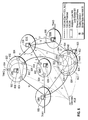
- FIG. 6 illustrates an exemplary interconnected multi-domain OTN for demonstrating the performance of one embodiment.
- FIG. 1 illustrates an interconnected multi-domain OTN 100 in accordance with one embodiment.
- the OTN 100 includes a plurality of domains, or areas, respectively designated CD1, CD2, CD3, M1, M2, and M3.
- Each of the domains CD1-CD3, M1-M3, includes a plurality of nodes, or routers, 102 each of which may be connected to a node in another one of the domains via an inter-domain link ("IrD link") 103 through a Network-to-Network interface ("NNI”) and to one or more clients 104 via a User-to-Network interface ("UNI 1.0").
- IrD link inter-domain link
- NNI Network-to-Network interface
- UNI 1.0 User-to-Network interface
- a node 102 may be connected to a management agent 106, such as a Craft Interface Terminal ("CIT”), an Element Management System (“EMS”), or a Network Management System (“NMS”), via a proprietary interface.
- a management agent 106 such as a Craft Interface Terminal ("CIT"), an Element Management System (“EMS”), or a Network Management System (“NMS”), via a proprietary interface.
- Nodes 102 within the same domain may be interconnected via intra-domain links (“IaD links”) 108.
- IaD links intra-domain links
- IrD-CSPF Inter-Domain CSPF
- SC Switched Connection
- SPC Soft Permanent Connection
- FIG. 2 illustrates a hierarchical routing structure 200 of an interconnected multi-domain OTN.
- Level 0 of the structure 200 represents the actual physical OTN.
- a plurality of routing domains CD1-CD7 are defined and each include one or more border nodes BN1-BN18.
- the domains CD1-CD7 may be interconnected via IrD links 202 between a pair of border nodes BN1-BN18 located in different domains.
- Internal nodes, represented by nodes 203, located within each of the domains CD1-CD7 may be connected to other internal nodes 203 or border nodes BN1-BN18 within the same domain via IaD links 206.
- each of the routing domains CD1-CD7 includes a controlling node S1-S7, respectively.
- Each controlling node S1-S7 includes a routing controller ("RC") (not shown in FIG. 2), which will be described in greater detail below with reference to FIG. 3.
- RC routing controller
- Level 1 is an abstraction of Level 0.
- the physical domains CD6 and CD7 are represented in Level 1 by a single abstract domain CD8.
- the physical domains CD1-CD3 are represented in Level 1 by an abstract domain CD9 and the physical domains CD4 and CD5 are represented in Level 1 by an abstract domain CD 10.
- the controlling nodes S1-S7 are represented in Level 1 by abstract nodes N1-N7, respectively. It will be noted that in Level 1, nodes N1, N4 and N7 are controlling nodes; the remaining nodes are border nodes.
- Level 2 is an abstraction of Level 1.
- the abstract domains CD8-CD10 are represented in Level 2 by a single abstract domain CD11.
- the three controlling nodes N1-N3 have been collapsed into a single controlling node N8.
- the abstract controlling nodes N4 and N7 are represented in Level 2 by abstract controlling nodes N9 and N10, respectively.
- the remaining nodes of Level 2 are border nodes.
- a pair of nodes within the same upper-level 2 domain e.g., nodes N6 and N7, are interconnected via an abstract IaD link 210.
- a pair of nodes of different upper-level domains e.g., nodes N3 and N4) are interconnected via an abstract IrD link 212.
- an embodiment of an IrD-CSPF procedure 301 utilizes the contents of two types of databases, including a Traffic Engineering Database (“TEDB”) 302 and a Domain Information Databases (“DIDB”) 304.
- TDB Traffic Engineering Database
- DIDB Domain Information Databases
- Construction of the TEDBs 302 and DIDBs 304 is a bottom-up procedure.
- a domain-specific intra-domain routing protocol entity (not shown), with appropriate extensions for TE, is hired and runs.
- This intra-domain routing entity is responsible for the discovery, maintenance, and advertisement of local topology and local resource availability (e.g., intra-domain TE links) within the respective domain.
- an RC is selected or appointed by the network operator with a global unique identifier "RC Id", which is advertised in the local domain.
- the RC is capable of identifying local border nodes, local inter-domain TE links, and local reachability information (i.e., the local reachable TNA addresses).
- the RC is also capable of aggregating the topology, e.g., via link aggregation, of its local domain.
- Each Level 0 RC representing its own underlying domain, joins the next higher hierarchical level (i.e., Level 1) domain thereof, in which an inter-domain routing protocol entity is hired.
- the RC of this next higher level hierarchical routing domain which are represented by the RC 300 of FIG. 3, exchange with each other the routing-related information, such as the local border nodes, the local inter-domain TE links, the local abstract inter-domain links and the local reachability information, of their underlying (in this case, Level 0) domains.
- Each RC 300 of the controlling nodes N1, N4 and N7 of the Level 1 domains creates a local TEDB 302 for recording all of the routing-related information and a local DIDB 304 for recording the reachability and other domain-related information.
- This process i.e., the hiring of an inter-domain routing protocol entity in the next higher hierarchical level and the exchanging of information between the RCs of that level
- this top level hierarchical routing domain is the domain CD11 in Level 2.
- inter-domain routing protocol entity running in RC 300 is separately treated from the inter-domain and the intra-domain routing entity running in its represented underlying domain.
- the Level 0 domains CD6 and CD7 are abstracted to the domain CD8 in Level 1, which is in turn abstracted to the domain CD11 in Level 2.
- domains CD8 and CD11 are "ancestor domains" of domains CD6 and CD7 and each node of the domains CD6 and CD7 is represented in each of the domains CD8 and CD11 by an "ancestor node.”
- the Level 0 domains CD1-CD3 are abstracted to the domain CD9 in Level 1, which is in turn abstracted to the domain CD11 in Level 2.
- domains CD9 and CD11 are ancestor domains of CD1-CD3 and each node of the domains CD1-CD3 is represented in each of the domains CD9 and CD11 by an ancestor node.
- the domains CD4 and CD5 are abstracted to the domain CD10 in Level 1, which is in turn abstracted to the domain CD11 in Level 2.
- domains CD10 and CD11 are ancestor domains of CD 4 and CD5 and each node in the domains CD4 and CD5 is represented in each of the domains CD 10 and CD11 by an ancestor node.
- the IrD-CSPF procedure 301 relies on the TEDB 302, which includes the attributes of all of the inter-domain and abstract intra-domain links, and the DIDB 304, which includes the domain-related information, such as the reachability of the up-level routing domain on which the IrD-CSPF procedure 301 operates.
- the limitations are always on the side of the databases 302, 304, due to some technical reasons, e.g., the IrD and the IaD routing protocols being used cannot provide a complete set of link attributes or the optical network equipment in the network lacks the necessary technologies for supporting certain traffic attributes.
- the primary objective of routing over a multi-domain interconnected OTN is to map a source-to-destination traffic demand into the optimal sequence of sub-paths within each domain.
- This routing functionality can be achieved by an alignment of an embodiment of the IrD-CSPF procedure described herein that is responsible for calculating the optimal path in the relevant upper-level domains in a top-down manner between two nodes that are in different Level 0 domains (starting from the lowest common ancestor hierarchical domain of the source node and the destination node) and the IaD-CSPF procedure, which calculates the ER in the Level 0 domains.
- the cost of an IaD abstract link in the current hierarchical level domain between a pair of nodes may not be the cost of the optimal path between the same node pair in this next lower hierarchical level domain.
- An embodiment of the IrD-CSPF procedure described herein is designed to support the calculation of an IrD ER for both Soft Permanent Connection (“SPC") and Soft Connection (“SC”) traffic demands.
- SPC Soft Permanent Connection
- SC Soft Connection
- an SPC traffic demand is initiated through a management agent, such as a Craft Interface Terminal (“CIT”), an Element Management System (“EMS”), or a Network Management System (“NMS”), while an SC traffic demand is initiated over a UNI signaling interface.
- CIT Craft Interface Terminal
- EMS Element Management System
- NMS Network Management System
- an SPC request must include the identifiers of the source and destination nodes, while an SC request must include the source and destination Transport Network Assigned (“TNA”) addresses.
- TAA Transport Network Assigned
- FIG. 4 is a flowchart of an embodiment of the path selection procedure given the hierarchical routing structure of an interconnected OTN. Specifically, FIG. 4 illustrates the path selection procedure for an SPC connection request (or traffic demand).
- a path selection component running in the node that receives the request (i.e., the source node) verifies the legibility of the traffic attributes included in the request.
- a determination is made in step 401 whether legibility was verified. If the traffic attributes are not legible, an error is generated in step 402; otherwise, in step 404, the lowest common ancestor hierarchical routing domain of the source and destination nodes is identified in a bottom-up manner.
- step 406 a determination is made whether both the source and the destination nodes are in the same bottom-tier, or "Level 0", domain. If so, in step 408, the ER calculation is performed inside the identified Level 0 domain by invoking the IaD-CSPF procedure described in the IaD-CSPF Patent Document referenced above. Otherwise, (i.e., if the source and destination nodes are not located in the same Level 0 domain), in step 410, the IrD-CSPF procedure, which is described in greater detail with reference to FIG. 5, is performed in the ancestor node of the source node in the identified upper-level domain.
- step 410 is an inter-domain ER at the identified upper-level that comprises an ordered sequence of abstract inter-domain links and/or abstract intra-domain links.
- a border node is identified in the immediately lower level hierarchical routing domain that is also an ancestor domain of the domain of the source node based on the information provided as a result of step 410. If the lower level hierarchical domain identified in step 412 is not in the bottom tier (Level 0) of the hierarchy, as determined in step 414, execution returns to step 410 and the IrD-CSPF procedure is performed on the ancestor node in this identified ancestor domain of the source node in calculating the ER toward the identified border node. Otherwise, execution proceeds to step 416, in which the IaD-CSPF is invoked in the Level 0 domains to calculate the ER through the border nodes identified by the IrD-CSPF.
- the path selection procedure for an SC request is identical to that described in FIG. 4 with respect to an SPC request, except that for an SC connection request, after verifying the legibility of the traffic attributes included in the request, the path selection component running in the source node of the SC connection request searches the local DIDB, which includes the domain relevant information, such as domain switching capability, domain shared risk group, and domain reachability information for the bottom-tier domain, and makes sure that the node hosts the source TNA address is exactly the source node of the SC connection request (note that a node is identified by the pair ⁇ routing controller identifier, node address>).
- the path selection component identifies the lowest common ancestor routing domain of the source and the destination TNA addresses in the hierarchical structure of the network and maps these TNA addresses to the identifiers of nodes (in the identified common ancestor domain) that host these TNA addresses, respectively. It will be appreciated that the lookup procedure of the TNA addresses uses the longest prefix matching method, as the TNA addresses may be maintained in the DIDBs in summarization formats. The remainder of the path selection procedure is the same as that for an SPC connection request as described above.
- the main features of the IrD-CSPF procedure are:
- the IrD-CSPF can be described as comprising three functional steps, as illustrated in FIG. 5.
- step 500 the top-level network graph is constructed.
- step 502 the source and destination TNA addresses are mapped.
- step 504 the ER is calculated using a modified Dijkstra's SPF algorithm.
- the step of building the top-level network graph (step 500) will be described in greater detail.
- the step 500 uses as inputs the TEDB 302, Connection Traffic Attributes ("CTAs") (switching type, encoding type, elementary signaling type, and number to be concatenated), Service Level (“SL”) (connection protection type), and Diversity (the link/node/SRLG set for an existing ER).
- CTAs Connection Traffic Attributes
- SL Service Level
- Diversity the link/node/SRLG set for an existing ER
- the output is the Network Graph ("dGraph”) and an Error Code ("errorCode”).
- the IrD-CSPF verifies the given Connection Traffic Attributes and Service Level and, based on the verified CTAs and SL and the Diversity information, creates the Network Graph or an Error Code.
- step 500 Exemplary pseudocode for implementing step 500 is set forth below:
- This step uses as inputs the DIDB 304, the Network Graph (dGraph), the Source TNA Address (“srcTNA”), and the Destination TNA Address (“dstTNA").
- the IrD-CSPF verifies the given source and destination TNA addresses (which are included in an SC connection request) and maps them to an ⁇ srcRCId, srcNodeAddr> list and an ⁇ dstRCId, dstNodeAddr> list, respectively.
- the IrD-CSPF maps them to the ⁇ sRCId, sNodeAddr> pair and the ⁇ dRCId, dNodeAddr> pair, respectively.
- the ⁇ sRCId, sNodeAddr> pair and the ⁇ dRCId, dNodeAddr> pair may not occur in the dGraph.
- the RC in a certain domain may hide the address of the node that hosts a TNA at the time it is advertising the TNA. If this is the case, the following procedure, illustrated in pseudocode, may be applied to solve this problem:
- step 504 The step of calculating the ER using a modified Dijkstra's SPF algorithm (step 504, FIG. 5) will be now described in greater detail.
- This step uses as inputs the Network Graph (dGraph), the ⁇ srcRCId, srcNodeAddr> list and the ⁇ dstRCId, dstNodeAddr> list.
- step 504 between a specific combination ( ⁇ srcRCId, srcNodeAddr>, ⁇ dstRCId, dstNodeAddr>), a modified Dijkstra's SPF algorithm is applied so that the computation is terminated as soon as the ⁇ dstRCId, dstNodeAddr> is reached, so as to achieve a better performance.
- This step may achieve the optimal ER in the network.
- the resultER is defined as the cheapest ER among the optimal ERs achieved for all possible combinations of ( ⁇ srcRCId, srcNodeAddr>, ⁇ dstRCId, dstNodeAddr>) for the ⁇ srcRCId, srcNodeAddr> list and the ⁇ dstRCId, dstNodeAddr> list.
- FIG. 6 depicts an interconnected multi-domain OTN 600.
- Domains ION2, ION5, and ION8 are examples of domains in which abstract IaD links, represented by links 602, are advertised by an IrD routing protocol for each pair of border nodes 604 within a single domain.
- Domains ION1, ION7, and ION9 are examples of domains with a single routing node 606 that is the RC in each single domain.
- the IrD adjacencies are configured between ION1 & ION 2, ION1 & ION5, ION1 & ION8, ION2 & ION7, ION2 & ION8, ION6 & ION7, ION7 & ION8, IOON7 & ION9 and ION8 & ION9.
- the addresses of the RCs 606 are assigned in the following manner.
- the RC identifier is with the address (RCId) 192.168.20.x and the border nodes' addresses in a routing domain IONx are assigned as xx.xx.xx.1, xx.xx.xx.2, and so on.
- the four border nodes addresses are 22.22.22.1, 22.22.22.2, 22.22.22.3, and 22.22.22.4, respectively.
- TNA1 and ION2 will be considered and it will be assumed that the current domain is ION1.
- the TEDB of each RC 606 includes the following link state information: A. One inter-domain link (advertized by routing controller 192.168.20.1) srcRCId 192.168.20.1 srcNodeAddr 192.168.20.1 localIfId 1 remoteIfId 3 destRCId 192.168.20.2 destNodeAddr 22.22.22.3 protection type unprotected cost 5 switch capability TDM signaling type STS-48c/VC4-16c time slots 10 SRLG IDs 15, 25 B.
- the DIDB of each RC 606 includes the following reachability information: TNA1 TNA Address 19.19.19.1 RCId 192.168.20.1 Host Node Addr 192.168.20.1 TNA2 TNA Address 29.29.29.0/24 RCId 192.168.20.2 Host Node Addr 22.22.22.4
- SC Request [Connection Request] srcTnaAddr 19.19.19.1 dstTnaAddr 29.29.29.4 srcRC 0 srcNode 0 dstRC 0 dstNode 0 switchingType TDM IspEncodingType SONET_SDH elementaryType STS3cSPE_VC4 concatenationType concatenation_standard numberOfConcatenation 16 directionality Bidirectional protectionType unprotected nodeSet Null linkSet Null srlgSet Null [Execution Request] Calculation Time 454 x 10 -6 seconds.
- the present invention advantageously provides a method and system for implementing an inter-domain constraint-based shortest path first ("IrD-CSPF”) technique for supporting hierarchical routing in interconnected multi-domain OTNs.
- IrD-CSPF inter-domain constraint-based shortest path first
Abstract
Description
- This application discloses subject matter related to the subject matter disclosed in commonly owned, copending U.S. Patent Application No. 10/320,286 (Attorney Docket No. 1285-0110US; Alcatel Reference No. 139059), entitled "A CONSTRAINT-BASED SHORTEST PATH FIRST METHOD FOR DYNAMICALLY SWITCHED OPTICAL TRANSPORT", filed December 16, 2002, in the names of Fuming Wu and Frederick H. Skoog, which is hereby incorporated by reference in its entirety for all purposes.
- The present invention generally relates to interconnected multi-domain optical transport networks ("OTNs"). More particularly, and not by way of any limitation, the present invention is directed to an inter-domain constraint-based shortest path first ("IrD-CSPF") technique for supporting hierarchical routing in such networks.
- Conventional IP-centric inter-domain routing protocols use different technologies to optimize routes from a source address to a destination address. For example, Routing Information Protocol ("RIP") uses the Bellman-Ford algorithm to calculate the minimum number of hops from source to destination. Open Shortest Path First ("OSPF") and Intermediate System-to-Intermediate System ("IS-IS") protocols use Dijkstra's Shortest Path First ("SPF") algorithm to achieve a path with minimum cost, the measure of which is set by the network administrator. In Border Gateway Protocol ("BGP"), path selection is mainly influenced by policy attributes and local preference, while Interior Gateway Protocol ("IGP") metrics are not directly used.
- Constraint-based routing in Generalized Multi-Protocol Label Switching ("GMPLS") control planes in OTNs is one of the main processes required for on-demand service provisioning (or bandwidth-on-demand) and for dynamic service restoration. In constraint-based routing, routing protocols calculate a path from a source to destination transport network element ("TNE") that is optimal and does not violate a given set of constraints. Route setup between the given source and destination TNEs takes place at the source TNE, whereas in conventional IP routing, a path or route is computed in a distributed fashion by every router in a network. In addition to resource utilization optimization, the focus of constraint-based routing is on optimization of performance and ease of administration.
- Under the current heterogeneous multi-carrier and multi-vendor networking environment, an interconnected OTN may be partitioned into multiple domains. Typically, a domain is defined as a portion of the network that has a clear demarcation boundary based on technology, business, service, technical administration, or architectural function. Given an interconnected multi-domain OTN, a hierarchical routing structure can be created using a feeding-up procedure described in
Chapter 3 of "Private Network-Network Interface Specification Version 1.1", ATM Forum af-pnni-0055.002, April 2002 (hereinafter "PNNI Version 1.1"). It is worth noting that, for multi-node domain with border node representation, a link aggregation technique is a key in constructing the next higher hierarchical level from the current hierarchical level. - A primary objective of routing over an interconnected multi-domain OTN is to map a source-to-destination traffic demand into the optimal sequence of sub-paths within each transit domain. Conventional routing protocols cannot perform the functionality of constraint based hierarchical routing in interconnected multi-domain OTNs. The autonomous systems in BGP and the areas in OSPF are required to be controlled by the same administrative entity of a single carrier. Moreover, routing in the aforementioned conventional inter-domain IP routing protocols is not based on the traffic engineering performance criteria and/or does not support the bandwidth-on-demand service requirement. Although traffic engineering ("TE") and GMPLS extensions existing for some of the conventional IP routing protocols (e.g., GMPLS OSPF-TE and GMPLS IS-IS TE), they are still not fit for hierarchical routing in interconnected multi-domain OTNs.
- For example, GMPLS OSPF-TE (equipped with both an intra-domain ("IaD") CSPF procedure such as that described in U.S. Patent Application Serial No. 10/320,286 entitled A CONSTRAINT-BASED SHORTEST PATH FIRST METHOD FOR DYNAMICALLY SWITCHED OPTICAL TRANSPORT (hereinafter "IaD-CSPF Patent Document", which has been incorporated by reference in its entirety, and a domain/link aggregation technique) has a limitation of two hierarchy levels, routing areas, and backbone areas. This solution is deficient, therefore, in cases in which a carrier requests to have more hierarchy levels according to the operation structures, technology, business, service, technical administration and/or architectural functions of its network(s).
- All of the existing algorithms described above are aimed at the calculation of the optimal route or path for best-effort traffic demands. These algorithms do not support bandwidth-guaranteed services. Moreover, the IaD-CSPF technique described in the IaD-CSPF Patent Document is designed for path calculation for Soft Permanent Connection ("SPC") connection requests of intra-domain constraint-based routing in GMPLS OTNs.
- Accordingly, the present invention advantageously provides method and system for implementing an inter-domain constraint-based shortest path first ("IrD-CSPF") technique for supporting hierarchical routing in interconnected multi-domain OTNs.
- In one embodiment, the invention is a method for calculating a network path in an interconnected multi-domain network. The method comprises receiving a path setup request message for a new traffic flow in the network, wherein the path setup request message identifies a source node in one domain of the network and a destination node in a second domain of the network; determining a common ancestor hierarchical routing domain that includes ancestor nodes of both the source and destination nodes; calculating an inter-domain path from the ancestor node of the source node to the ancestor node of the destination node in the common ancestor hierarchical routing domain that determines, for each lower-level domain, border nodes in the domain from the source node to the destination node using a traffic engineering network database ("TEDB") that stores network topology information for the common ancestor hierarchical routing domain; and for each bottom-level domain, calculating an intra-domain path between the border nodes that were determined for the domain.
- In another embodiment, the invention comprises a method for calculating a path through an interconnected multi-domain network responsive to receipt of a path setup request message, the path setup request message identifying a source node and a destination node, wherein the network can be represented by an hierarchical routing structure comprising a bottom level and at least one upper level. The method comprises determining whether the source and destination nodes are in a common bottom level domain; if the source and destination nodes are not in a common bottom level domain, determining a common ancestor hierarchical routing domain that includes ancestor nodes of both the source and destination nodes; calculating an inter-domain path from the ancestor node of the source node to the ancestor node of the destination node in the common ancestor hierarchical routing domain, wherein the inter-domain path specifies, for each immediately lower-level domain, border nodes in the domain along a path from the source node to the destination node; and for each bottom-level domain, calculating an intra-domain path between the border nodes that were determined for the domain.
- In another embodiment, the invention comprises a system for calculating a network path in an interconnected multi-domain network. The system comprises means for receiving a path setup request message for a new traffic flow in the network, wherein the path setup request message identifies a source node in one domain of the network and a destination node in a second domain of the network; means for determining a common ancestor hierarchical routing domain that includes ancestor nodes of both the source and destination nodes;
means for calculating an inter-domain path from the ancestor node of the source node to the ancestor node of the destination node in the common ancestor hierarchical routing domain that determines, for each lower-level domain, border nodes in the domain from the source node to the destination node using a traffic engineering network database ("TEDB") that stores network topology information for the common ancestor hierarchical routing domain; and means for calculating an intra-domain path between the border nodes that were determined for each bottom-level domain. - In yet another embodiment, the invention comprises an apparatus for calculating a network path in an interconnected multi-domain network representable by a hierarchical routing structure comprising a bottom hierarchical level and at least one upper hierarchical level. The apparatus comprises a routing controller ("RC") located at a domain of each upper hierarchical level; a Traffic Engineering Database ("TEDB") associated with each RC; a Domain Information Database ("DIDB") associated with each RC; and an inter-domain Constraint Based Shortest Path First ("IrD-CSPF") procedure for calculating an inter-domain path from an ancestor node of a source node identified in a path setup request message to an ancestor node of a destination node identified in the path setup request message, wherein the ancestor nodes are located in a lowest common ancestor hierarchy domain of the identified source and destination nodes.
- A more complete understanding of the present invention may be had by reference to the following Detailed Description when taken in conjunction with the accompanying drawings wherein:
- FIG. 1 illustrates an interconnected multi-domain OTN in accordance with one embodiment;
- FIG. 2 illustrates a hierarchical routing structure representation of an interconnected multi-domain OTN in accordance with one embodiment;
- FIG. 3 is a block diagram of a routing controller of an upper hierarchical level of the routing structure of FIG. 2;
- FIG. 4 is a flowchart of a path selection procedure in accordance with one embodiment;
- FIG. 5 is a flowchart of an IrD-CSPF procedure in accordance with one embodiment; and
- FIG. 6 illustrates an exemplary interconnected multi-domain OTN for demonstrating the performance of one embodiment.
- In the drawings, like or similar elements are designated with identical reference numerals throughout the several views thereof, and the various elements depicted are not necessarily drawn to scale.
- FIG. 1 illustrates an interconnected
multi-domain OTN 100 in accordance with one embodiment. As shown in FIG. 1, the OTN 100 includes a plurality of domains, or areas, respectively designated CD1, CD2, CD3, M1, M2, and M3. Each of the domains CD1-CD3, M1-M3, includes a plurality of nodes, or routers, 102 each of which may be connected to a node in another one of the domains via an inter-domain link ("IrD link") 103 through a Network-to-Network interface ("NNI") and to one ormore clients 104 via a User-to-Network interface ("UNI 1.0"). Additionally, anode 102 may be connected to amanagement agent 106, such as a Craft Interface Terminal ("CIT"), an Element Management System ("EMS"), or a Network Management System ("NMS"), via a proprietary interface.Nodes 102 within the same domain may be interconnected via intra-domain links ("IaD links") 108. - As will be described in greater detail below, one embodiment of an Inter-Domain CSPF ("IrD-CSPF") technique supports both Switched Connection ("SC") requests, which are initiated over a UNI signaling interface, and Soft Permanent Connection ("SPC") requests, which are initiated through a management agent, such as the
management agent 106, with a wide set of constraints. - As previously noted, given an interconnected multi-domain OTN, such as the
OTN 100, a hierarchical routing structure representation can be created using a "feeding up" procedure. FIG. 2 illustrates ahierarchical routing structure 200 of an interconnected multi-domain OTN.Level 0 of thestructure 200 represents the actual physical OTN. A plurality of routing domains CD1-CD7 are defined and each include one or more border nodes BN1-BN18.
The domains CD1-CD7 may be interconnected viaIrD links 202 between a pair of border nodes BN1-BN18 located in different domains. Internal nodes, represented bynodes 203, located within each of the domains CD1-CD7 may be connected to otherinternal nodes 203 or border nodes BN1-BN18 within the same domain viaIaD links 206. - Additionally, each of the routing domains CD1-CD7 includes a controlling node S1-S7, respectively. Each controlling node S1-S7 includes a routing controller ("RC") (not shown in FIG. 2), which will be described in greater detail below with reference to FIG. 3.
-
Level 1 is an abstraction ofLevel 0. In particular, the physical domains CD6 and CD7 are represented inLevel 1 by a single abstract domain CD8. Similarly, the physical domains CD1-CD3 are represented inLevel 1 by an abstract domain CD9 and the physical domains CD4 and CD5 are represented inLevel 1 by anabstract domain CD 10. The controlling nodes S1-S7 are represented inLevel 1 by abstract nodes N1-N7, respectively. It will be noted that inLevel 1, nodes N1, N4 and N7 are controlling nodes; the remaining nodes are border nodes. -
Level 2 is an abstraction ofLevel 1. In particular, the abstract domains CD8-CD10 are represented inLevel 2 by a single abstract domain CD11. The three controlling nodes N1-N3 have been collapsed into a single controlling node N8. The abstract controlling nodes N4 and N7 are represented inLevel 2 by abstract controlling nodes N9 and N10, respectively. The remaining nodes ofLevel 2 are border nodes. A pair of nodes within the same upper-level 2 domain (e.g., nodes N6 and N7), are interconnected via anabstract IaD link 210. A pair of nodes of different upper-level domains (e.g., nodes N3 and N4) are interconnected via anabstract IrD link 212. - Referring to FIG. 3, and as will be described in greater detail hereinbelow, within each
RC 300 in each of the controlling nodes of each hierarchical Level k, where k > 0, an embodiment of an IrD-CSPF procedure 301 utilizes the contents of two types of databases, including a Traffic Engineering Database ("TEDB") 302 and a Domain Information Databases ("DIDB") 304. The following briefly describes the creation and maintenance mechanisms of thedatabases - Construction of the
TEDBs 302 andDIDBs 304 is a bottom-up procedure. Referring to FIGs. 2 and 3, within each domain CD1-CD7 of the bottom-tier (i.e., Level 0) of the represented network, a domain-specific intra-domain routing protocol entity (not shown), with appropriate extensions for TE, is hired and runs. This intra-domain routing entity is responsible for the discovery, maintenance, and advertisement of local topology and local resource availability (e.g., intra-domain TE links) within the respective domain. For the controlling node S1-S7 of each individual domain CD1-CD7, respectively, of the bottom tier, an RC is selected or appointed by the network operator with a global unique identifier "RC Id", which is advertised in the local domain. The RC is capable of identifying local border nodes, local inter-domain TE links, and local reachability information (i.e., the local reachable TNA addresses). The RC is also capable of aggregating the topology, e.g., via link aggregation, of its local domain. - Each
Level 0 RC, representing its own underlying domain, joins the next higher hierarchical level (i.e., Level 1) domain thereof, in which an inter-domain routing protocol entity is hired. The RC of this next higher level hierarchical routing domain, which are represented by theRC 300 of FIG. 3, exchange with each other the routing-related information, such as the local border nodes, the local inter-domain TE links, the local abstract inter-domain links and the local reachability information, of their underlying (in this case, Level 0) domains. - Each
RC 300 of the controlling nodes N1, N4 and N7 of theLevel 1 domains (CD8-CD10) creates alocal TEDB 302 for recording all of the routing-related information and alocal DIDB 304 for recording the reachability and other domain-related information. This process (i.e., the hiring of an inter-domain routing protocol entity in the next higher hierarchical level and the exchanging of information between the RCs of that level) is performed repeatedly, in a bottom-to-top fashion, until the top-level hierarchical routing domain is reached. In FIG. 2, this top level hierarchical routing domain is the domain CD11 inLevel 2. - It will be appreciated that the inter-domain routing protocol entity running in
RC 300 is separately treated from the inter-domain and the intra-domain routing entity running in its represented underlying domain. - As shown in FIG. 2, the
Level 0 domains CD6 and CD7 are abstracted to the domain CD8 inLevel 1, which is in turn abstracted to the domain CD11 inLevel 2. Accordingly, domains CD8 and CD11 are "ancestor domains" of domains CD6 and CD7 and each node of the domains CD6 and CD7 is represented in each of the domains CD8 and CD11 by an "ancestor node." Similarly, theLevel 0 domains CD1-CD3 are abstracted to the domain CD9 inLevel 1, which is in turn abstracted to the domain CD11 inLevel 2. Accordingly, domains CD9 and CD11 are ancestor domains of CD1-CD3 and each node of the domains CD1-CD3 is represented in each of the domains CD9 and CD11 by an ancestor node. Finally, the domains CD4 and CD5 are abstracted to the domain CD10 inLevel 1, which is in turn abstracted to the domain CD11 inLevel 2. Accordingly, domains CD10 and CD11 are ancestor domains ofCD 4 and CD5 and each node in the domains CD4 and CD5 is represented in each of thedomains CD 10 and CD11 by an ancestor node. - As previously indicated, the IrD-
CSPF procedure 301 relies on theTEDB 302, which includes the attributes of all of the inter-domain and abstract intra-domain links, and theDIDB 304, which includes the domain-related information, such as the reachability of the up-level routing domain on which the IrD-CSPF procedure 301 operates. Generally, the limitations are always on the side of thedatabases - The primary objective of routing over a multi-domain interconnected OTN is to map a source-to-destination traffic demand into the optimal sequence of sub-paths within each domain. This routing functionality can be achieved by an alignment of an embodiment of the IrD-CSPF procedure described herein that is responsible for calculating the optimal path in the relevant upper-level domains in a top-down manner between two nodes that are in
different Level 0 domains (starting from the lowest common ancestor hierarchical domain of the source node and the destination node) and the IaD-CSPF procedure, which calculates the ER in theLevel 0 domains. In general, the cost of an IaD abstract link in the current hierarchical level domain between a pair of nodes (note that these two nodes must be border nodes in a next lower hierarchical level domain, which is a multi-node domain with border node representation) may not be the cost of the optimal path between the same node pair in this next lower hierarchical level domain. - An embodiment of the IrD-CSPF procedure described herein is designed to support the calculation of an IrD ER for both Soft Permanent Connection ("SPC") and Soft Connection ("SC") traffic demands. By definition, an SPC traffic demand is initiated through a management agent, such as a Craft Interface Terminal ("CIT"), an Element Management System ("EMS"), or a Network Management System ("NMS"), while an SC traffic demand is initiated over a UNI signaling interface. Accordingly, besides the specific traffic attribute constraints, an SPC request must include the identifiers of the source and destination nodes, while an SC request must include the source and destination Transport Network Assigned ("TNA") addresses.
- FIG. 4 is a flowchart of an embodiment of the path selection procedure given the hierarchical routing structure of an interconnected OTN. Specifically, FIG. 4 illustrates the path selection procedure for an SPC connection request (or traffic demand). In
step 400, responsive to an SPC request, a path selection component running in the node that receives the request (i.e., the source node) verifies the legibility of the traffic attributes included in the request. A determination is made instep 401 whether legibility was verified. If the traffic attributes are not legible, an error is generated instep 402; otherwise, instep 404, the lowest common ancestor hierarchical routing domain of the source and destination nodes is identified in a bottom-up manner. - In
step 406, a determination is made whether both the source and the destination nodes are in the same bottom-tier, or "Level 0", domain. If so, instep 408, the ER calculation is performed inside the identifiedLevel 0 domain by invoking the IaD-CSPF procedure described in the IaD-CSPF Patent Document referenced above. Otherwise, (i.e., if the source and destination nodes are not located in thesame Level 0 domain), instep 410, the IrD-CSPF procedure, which is described in greater detail with reference to FIG. 5, is performed in the ancestor node of the source node in the identified upper-level domain. - The result of
step 410 is an inter-domain ER at the identified upper-level that comprises an ordered sequence of abstract inter-domain links and/or abstract intra-domain links. Instep 412, a border node is identified in the immediately lower level hierarchical routing domain that is also an ancestor domain of the domain of the source node based on the information provided as a result ofstep 410. If the lower level hierarchical domain identified instep 412 is not in the bottom tier (Level 0) of the hierarchy, as determined instep 414, execution returns to step 410 and the IrD-CSPF procedure is performed on the ancestor node in this identified ancestor domain of the source node in calculating the ER toward the identified border node. Otherwise, execution proceeds to step 416, in which the IaD-CSPF is invoked in theLevel 0 domains to calculate the ER through the border nodes identified by the IrD-CSPF. - It will be appreciated that the path selection procedure for an SC request is identical to that described in FIG. 4 with respect to an SPC request, except that for an SC connection request, after verifying the legibility of the traffic attributes included in the request, the path selection component running in the source node of the SC connection request searches the local DIDB, which includes the domain relevant information, such as domain switching capability, domain shared risk group, and domain reachability information for the bottom-tier domain, and makes sure that the node hosts the source TNA address is exactly the source node of the SC connection request (note that a node is identified by the pair <routing controller identifier, node address>).
- Additionally, in
step 404, the path selection component identifies the lowest common ancestor routing domain of the source and the destination TNA addresses in the hierarchical structure of the network and maps these TNA addresses to the identifiers of nodes (in the identified common ancestor domain) that host these TNA addresses, respectively. It will be appreciated that the lookup procedure of the TNA addresses uses the longest prefix matching method, as the TNA addresses may be maintained in the DIDBs in summarization formats. The remainder of the path selection procedure is the same as that for an SPC connection request as described above. - The main features of the IrD-CSPF procedure are:
- 1. Connection Types: SPC and SC;
- 2. Directionality: unidirectional signaled connection and bidirectional singled connection
- 3. Link Interface Identifier Types: unnumbered (unsigned integer index) and numbered (Ipv4 address);
- 4. Diversities: the requested ER can be SRLG, node, or link diverse with an existing ER;
- 5. Protection Types: AnyType, which is a customer defined protection type indicating that the requester does not care about the protection type of the ER hops), unprotected, protected (dedicated 1:1 and dedicated 1+1), and enhanced link.
- 6. Reachability: UNI connection endpoints are identified by TNA addresses. Each TNA address is a global unique address assigned by the OTN to a TE link connecting a TNE and a client. The IrD-CSPF supports Ipv4 TNA addresses for both flat and summarization formats;
- 7. Encoding Type: SONET/SDH, Lambda and Fiber
- 8. Switching Type: TDM, LSC, and FSC;
- 9. Concatenation: single type standard concatenation of elementary signaling types.
- Assuming that a given interconnected multi-domain OTN has two hierarchical levels (i.e., a top level ("
Level 1") and a bottom level ("Level 0")), the IrD-CSPF can be described as comprising three functional steps, as illustrated in FIG. 5. Instep 500, the top-level network graph is constructed. Instep 502, the source and destination TNA addresses are mapped. Instep 504, the ER is calculated using a modified Dijkstra's SPF algorithm. Each of steps 500-504 will be described in greater detail below. - The step of building the top-level network graph (step 500) will be described in greater detail. The
step 500 uses as inputs theTEDB 302, Connection Traffic Attributes ("CTAs") (switching type, encoding type, elementary signaling type, and number to be concatenated), Service Level ("SL") (connection protection type), and Diversity (the link/node/SRLG set for an existing ER). The output is the Network Graph ("dGraph") and an Error Code ("errorCode"). In this step, the IrD-CSPF verifies the given Connection Traffic Attributes and Service Level and, based on the verified CTAs and SL and the Diversity information, creates the Network Graph or an Error Code. - Exemplary pseudocode for implementing
step 500 is set forth below:
- The step of mapping the source and destination TNA addresses (
step 502, FIG. 5) will be now described in greater detail. This step uses as inputs theDIDB 304, the Network Graph (dGraph), the Source TNA Address ("srcTNA"), and the Destination TNA Address ("dstTNA"). In this step, the IrD-CSPF verifies the given source and destination TNA addresses (which are included in an SC connection request) and maps them to an <srcRCId, srcNodeAddr> list and an <dstRCId, dstNodeAddr> list, respectively. When verifying the Source and Destination TNA addresses, based on the contents of the DIDB, the IrD-CSPF maps them to the <sRCId, sNodeAddr> pair and the <dRCId, dNodeAddr> pair, respectively. - Exemplary pseudocode for carrying out this portion of
step 502 is set forth below:
- Unfortunately, the <sRCId, sNodeAddr> pair and the <dRCId, dNodeAddr> pair may not occur in the dGraph. For example, For security considerations, the RC in a certain domain may hide the address of the node that hosts a TNA at the time it is advertising the TNA. If this is the case, the following procedure, illustrated in pseudocode, may be applied to solve this problem:


- The step of calculating the ER using a modified Dijkstra's SPF algorithm (
step 504, FIG. 5) will be now described in greater detail. This step uses as inputs the Network Graph (dGraph), the <srcRCId, srcNodeAddr> list and the <dstRCId, dstNodeAddr> list. Instep 504, between a specific combination (<srcRCId, srcNodeAddr>, <dstRCId, dstNodeAddr>), a modified Dijkstra's SPF algorithm is applied so that the computation is terminated as soon as the <dstRCId, dstNodeAddr> is reached, so as to achieve a better performance. This step may achieve the optimal ER in the network. The resultER is defined as the cheapest ER among the optimal ERs achieved for all possible combinations of (<srcRCId, srcNodeAddr>, <dstRCId, dstNodeAddr>) for the <srcRCId, srcNodeAddr> list and the <dstRCId, dstNodeAddr> list. - Exemplary pseudocode For performing
step 504 is set forth below:

- An example of IrD path calculation using the IrD-CSPF procedure will now be provided. Given an interconnected multi-domain OTN with a two-level hierarchical structure, the domain representation of the network is depicted in FIG. 6.
- There are two different approaches for the summarization of IaD routing information. For the sake of completeness, both of these are covered in this example, and shown in FIG. 6, which depicts an interconnected multi-domain OTN 600. Domains ION2, ION5, and ION8 are examples of domains in which abstract IaD links, represented by
links 602, are advertised by an IrD routing protocol for each pair ofborder nodes 604 within a single domain. Domains ION1, ION7, and ION9 are examples of domains with asingle routing node 606 that is the RC in each single domain. At the top-level (or "IrD level"), the IrD adjacencies are configured between ION1 &ION 2, ION1 & ION5, ION1 & ION8, ION2 & ION7, ION2 & ION8, ION6 & ION7, ION7 & ION8, IOON7 & ION9 and ION8 & ION9. - It will be assumed that the addresses of the
RCs 606 are assigned in the following manner. For domain IONx, the RC identifier is with the address (RCId) 192.168.20.x and the border nodes' addresses in a routing domain IONx are assigned as xx.xx.xx.1, xx.xx.xx.2, and so on. For example, in routing domain ION2, the four border nodes addresses are 22.22.22.1, 22.22.22.2, 22.22.22.3, and 22.22.22.4, respectively. Finally, the reachable addresses are TNA1=19.19.19.1, TNA2=29.29.29.0/24 (summarization format), TNA3=39.39.39.1, and TNA4=49.49.49.1. For simplicity, only domains ION1 and ION2 will be considered and it will be assumed that the current domain is ION1. - The TEDB of each
RC 606 includes the following link state information:
A. One inter-domain link (advertized by routing controller 192.168.20.1)srcRCId 192.168.20.1 srcNodeAddr 192.168.20.1 localIfId 1 remoteIfId 3 destRCId 192.168.20.2 destNodeAddr 22.22.22.3 protection type unprotected cost 5 switch capability TDM signaling type STS-48c/VC4- 16c time slots 10 SRLG IDs 15, 25
B. One inter-domain link (advertized by routing controller 192.168.20.2)srcRCId 192.168.20.2 srcNodeAddr 22.22.22.3 localIfId 3 remoteIfId 1 destRCId 192.168.20.1 destNodeAddr 192.168.20.1 protection type unprotected cost 5 switch capability TDM signaling type STS-48c/VC4- 16c time slots 10 SRLG IDs 15, 25
C. 12 abstract intra-domain links (advertised by routing controller 192.168.20.2)link 1 srcRCId 192.168.20.2 srcNodeAddr 22.22.22.3 localIfId 34 remoteIfId 43 destRCId 192.168.20.2 destNodeAddr 22.22.22.4 protection type unprotected cost 15 switch capability TDM signaling type STS-48c/VC4-16c time slots 3 SRLG IDs 35, 45 link 2 srcRCId 192.168.20.2 srcNodeAddr 22.22.22.4 localIfId 43 remoteIfId 34 destRCId 192.168.20.2 destNodeAddr 22.22.22.3 protection type unprotected cost 15 switch capability TDM signaling type STS-48c/VC4-16c time slots 3 SRLG IDs 35, 45 link 3 srcRCId 192.168.20.2 srcNodeAddr 22.22.22.3 localIfId 31 remoteIfId 13 destRCId 192.168.20.2 destNodeAddr 22.22.22.1 protection type unprotected cost 3 switch capability TDM signaling type STS-48c/VC4-16c time slots 5 SRLG IDs 55, 65 link 4 srcRCId 192.168.20.2 srcNodeAddr 22.22.22.1 localIfId 13 remoteIfId 31 destRCId 192.168.20.2 destNodeAddr 22.22.22.3 protection type unprotected cost 3 switch capability TDM signaling type STS-48c/VC4-16c time slots 5 SRLG IDs 55, 65 link 5 srcRCId 192.168.20.2 srcNodeAddr 22.22.22.3 localIfId 32 remoteIfId 23 destRCId 192.168.20.2 destNodeAddr 22.22.22.2 protection type unprotected cost 4 switch capability TDM signaling type STS-48c/VC4-16c time slots 10 SRLG IDs 75, 85 link 6 srcRCId 192.168.20.2 srcNodeAddr 22.22.22.2 localIfId 23 remoteIfId 32 destRCId 192.168.20.2 destNodeAddr 22.22.22.3 protection type unprotected cost 4 switch capability TDM signaling type STS-48c/VC4-16c time slots 10 SRLG IDs 75, 85 link 7 srcRCId 192.168.20.2 srcNodeAddr 22.22.22.1 localIfId 12 remoteIfId 21 destRCId 192.168.20.2 destNodeAddr 22.22.22.2 protection type unprotected cost 2 switch capability TDM signaling type STS-48c/VC4-16c time slots 5 SRLG IDs 95, 105 link 8 srcRCId 192.168.20.2 srcNodeAddr 22.22.22.2 localIfId 21 remoteIfId 12 destRCId 192.168.20.2 destNodeAddr 22.22.22.1 protection type unprotected cost 2 switch capability TDM signaling type STS-48c/VC4-16c time slots 5 SRLG IDs 95, 105 link 9 srcRCId 192.168.20.2 srcNodeAddr 22.22.22.1 localIfId 14 remoteIfId 41 destRCId 192.168.20.2 destNodeAddr 22.22.22.4 protection type unprotected cost 1 switch capability TDM signaling type STS-48c/VC4-16c time slots 8 SRLG IDs 115, 125 link 10 srcRCId 192.168.20.2 srcNodeAddr 22.22.22.4 localIfId 41 remoteIfId 14 destRCId 192.168.20.2 destNodeAddr 22.22.22.1 protection type unprotected cost 1 switch capability TDM signaling type STS-48c/VC4-16c time slots 8 SRLG IDs 115, 125 link 11 srcRCId 192.168.20.2 srcNodeAddr 22.22.22.2 localIfId 24 remoteIfId 42 destRCId 192.168.20.2 destNodeAddr 22.22.22.4 protection type unprotected cost 1 switch capability TDM signaling type STS-48c/VC4-16c time slots 4 SRLG IDs 135, 145 link 12 srcRCId 192.168.20.2 srcNodeAddr 22.22.22.4 localIfId 42 remoteIfId 24 destRCId 192.168.20.2 destNodeAddr 22.22.22.2 protection type unprotected cost 1 switch capability TDM signaling type STS-48c/VC4-16c time slots 4 SRLG IDs 135, 145 - The DIDB of each
RC 606 includes the following reachability information:TNA1 TNA Address 19.19.19.1 RCId 192.168.20.1 Host Node Addr 192.168.20.1 TNA2 TNA Address 29.29.29.0/24 RCId 192.168.20.2 Host Node Addr 22.22.22.4 - Assuming that an SC or SPC can be requested by the following interface:The following are the results of two sample runs:

1. SC Request[Connection Request] srcTnaAddr 19.19.19.1 dstTnaAddr 29.29.29.4 srcRC 0 srcNode 0 dstRC 0 dstNode 0 switchingType TDM IspEncodingType SONET_SDH elementaryType STS3cSPE_VC4 concatenationType concatenation_standard numberOfConcatenation 16 directionality Bidirectional protectionType unprotected nodeSet Null linkSet Null srlgSet Null [Execution Request] Calculation Time 454 x 10-6 seconds. CalcStatus=0 Result ER global cost=9 Hop 1LocalRCAddr 192.168.20.1 LocalNodeAddr 192.168.20.1 outIfId 1 RemoteRCAddr 192.168.20.2 RemoteNodeAddr 22.22.22.3 InIfId 3 SrlgIds {15, 25} Hop 2LocalRCAddr 192.168.20.2 LocalNodeAddr 22.22.22.3 outIfId 31 RemoteRCAddr 192.168.20.2 RemoteNodeAddr 22.22.22.1 InIfId 13 SrlgIds {55, 65} Hop 3LocalRCAddr 192.168.20.2 LocalNodeAddr 22.22.22.1 outIfId 14 RemoteRCAddr 192.168.20.2 RemoteNodeAddr 22.22.22.4 InIfId 41 SrlgIds {135, 145}
2. SPC Request[Connection Request] srcTnaAddr 0 dstTnaAddr 0 srcRC 192.168.20.1 srcNode 192.168.20.1 dstRC 192.168.20.2 dstNode 22.22.22.1 switchingType TDM IspEncodingType SONET_SDH elementaryType STS3cSPE_VC4 concatenationType concatenation_standard numberOfConcatenation 16 directionality Bidirectional protectionType unprotected nodeSet Null linkSet Null srlgSet Null [Execution Request] Calculation Time 405 x 10-6 seconds. CalcStatus=0 Result ER global cost=8 Hop 1LocalRCAddr 192.168.20.1 LocalNodeAddr 192.168.20.1 outIfId 1 RemoteRCAddr 192.168.20.2 RemoteNodeAddr 22.22.22.3 InIfId 3 SrlgIds {15, 25} Hop 2LocalRCAddr 192.168.20.2 LocalNodeAddr 22.22.22.3 outIfId 31 RemoteRCAddr 192.168.20.2 RemoteNodeAddr 22.22.22.1 InIfId 13 SrlgIds {55, 65} - Based upon the foregoing Detailed Description, it should be readily apparent that the present invention advantageously provides a method and system for implementing an inter-domain constraint-based shortest path first ("IrD-CSPF") technique for supporting hierarchical routing in interconnected multi-domain OTNs.
- It is believed that the operation and construction of the present invention will be apparent from the foregoing Detailed Description. While the exemplary embodiments of the invention shown and described have been characterized as being preferred, it should be readily understood that various changes and modifications could be made therein without departing from the scope of the present invention as set forth in the following claims.
Claims (10)
- A method for calculating a network path in an interconnected multi-domain network, the method comprising:receiving a path setup request message for a new traffic flow in the network, wherein the path setup request message identifies a source node in one domain of the network and a destination node in a second domain of the network;determining a common ancestor hierarchical routing domain that includes ancestor nodes of both the source and destination nodes;calculating an inter-domain path from the ancestor node of the source node to the ancestor node of the destination node in the common ancestor hierarchical routing domain that determines, for each lower-level domain, border nodes in the domain from the source node to the destination node using a traffic engineering network database ("TEDB") that stores network topology information for the common ancestor hierarchical routing domain; andfor each bottom-level domain, calculating an intra-domain path between the border nodes that were determined for the domain.
- The method of claim 1 wherein the determining is performed in a bottom-up manner.
- The method of claim 1 wherein the determining comprises determining a lowest common ancestor hierarchical routing domain that includes the ancestor node of the source node and the ancestor node of the destination node.
- The method of claim 1 wherein the path setup request message comprises a Soft Permanent Connection ("SPC") request.
- The method of claim 1 wherein the connection request comprises a Switched Connection ("SC") request.
- The method of claim 5 further comprising searching a local Domain Information Database ("DIDB") to confirm that a node that hosts a source TNA address is the source node.
- The method of claim 1 wherein the inter-domain path is calculated using an Inter-Domain Constraint-Based Shortest Path First ("IrD-CSPF") procedure.
- The method of claim 1 wherein the intra-domain path is calculated using an Intra-Domain CSPF ("IaD-CSPF") procedure.
- An apparatus for calculating a network path in an interconnected multi-domain network representable by a hierarchical routing structure comprising a bottom hierarchical level and at least one upper hierarchical level, the apparatus comprising:a routing controller ("RC") located at a domain of each upper hierarchical level;a Traffic Engineering Database ("TEDB") associated with each RC;a Domain Information Database ("DIDB") associated with each RC; andan inter-domain Constraint Based Shortest Path First ("IrD-CSPF") procedure for calculating an inter-domain path from an ancestor node of a source node identified in a path setup request message to an ancestor node of a destination node identified in the path setup request message, wherein the ancestor nodes are located in a lowest common ancestor hierarchy domain of the identified source and destination nodes.
- The apparatus of claim 9 further comprising, at each bottom level domain, an intra-domain CSPF ("IaD-CSPF") procedure for calculating a path through the domain between a pair of border nodes identified for the domain by the IrD-CSPF procedure.
Applications Claiming Priority (2)
| Application Number | Priority Date | Filing Date | Title |
|---|---|---|---|
| US10/392,227 US7215644B2 (en) | 2003-03-19 | 2003-03-19 | Inter-domain constraint-based shortest path first technique for supporting hierarchical routing in interconnected multi-domain optical transport networks |
| US392227 | 2003-03-19 |
Publications (3)
| Publication Number | Publication Date |
|---|---|
| EP1460808A2 true EP1460808A2 (en) | 2004-09-22 |
| EP1460808A3 EP1460808A3 (en) | 2006-02-08 |
| EP1460808B1 EP1460808B1 (en) | 2016-02-24 |
Family
ID=32824880
Family Applications (1)
| Application Number | Title | Priority Date | Filing Date |
|---|---|---|---|
| EP04005495.9A Expired - Lifetime EP1460808B1 (en) | 2003-03-19 | 2004-03-08 | Inter-Domain constraint-based shortest path first technique for supporting hierarchical routing in interconnected multi-domain optical transport networks |
Country Status (2)
| Country | Link |
|---|---|
| US (1) | US7215644B2 (en) |
| EP (1) | EP1460808B1 (en) |
Cited By (22)
| Publication number | Priority date | Publication date | Assignee | Title |
|---|---|---|---|---|
| EP1863235A1 (en) | 2006-06-02 | 2007-12-05 | Huawei Technologies Co., Ltd. | Method and system for multi-domain route computation |
| WO2008046322A1 (en) | 2006-10-16 | 2008-04-24 | Huawei Technologies Co., Ltd. | Distributed pce-based system and architecture in a multi-layer network |
| CN100396040C (en) * | 2005-02-22 | 2008-06-18 | 华为技术有限公司 | Method of path selecting in intelligent optical network |
| WO2008080251A1 (en) * | 2006-12-01 | 2008-07-10 | Zte Corporation | A hierarchical routing query method of automatic switched optical network |
| EP1953963A1 (en) * | 2005-11-24 | 2008-08-06 | Huawei Technologies Co., Ltd. | Method and system for realizing network connection service |
| CN100454837C (en) * | 2005-12-02 | 2009-01-21 | 华为技术有限公司 | Method for realizing cross-domain route separation |
| EP2056526A1 (en) * | 2006-09-26 | 2009-05-06 | Huawei Technologies Co., Ltd. | A method for processing the resource information of the traffic engineering link |
| WO2009067925A1 (en) | 2007-11-26 | 2009-06-04 | Huawei Technologies Co., Ltd. | A method, system and path computation element for obtaining path information |
| WO2009076815A1 (en) * | 2007-12-03 | 2009-06-25 | Huawei Technologies Co., Ltd. | Router and method of processing path message |
| WO2009092252A1 (en) * | 2007-12-29 | 2009-07-30 | Huawei Technologies Co., Ltd. | Routing computation method and system, and path computation element |
| EP2151959A1 (en) * | 2008-08-08 | 2010-02-10 | Hitachi Communication Technologies, Ltd. | Communication network system, path calculation device, and communication path establishment control method |
| US7813279B2 (en) | 2006-01-13 | 2010-10-12 | Futurewei Technologies, Inc. | System for rate management of aggregate-rate communication services |
| US7817550B2 (en) | 2006-01-13 | 2010-10-19 | Futurewei Technologies, Inc. | System for rate-control of aggregate-rate communication services |
| US7881192B2 (en) | 2006-01-13 | 2011-02-01 | Futurewei Technologies, Inc. | System for providing aggregate-rate communication services |
| EP2328307A1 (en) * | 2008-09-12 | 2011-06-01 | ZTE Corporation | Barrier boundary node and method for establishing connection between barrier bound ary nodes |
| CN102088413A (en) * | 2011-03-02 | 2011-06-08 | 华为技术有限公司 | Network flow shunting method, network node and network system |
| CN102347893A (en) * | 2010-07-30 | 2012-02-08 | 中兴通讯股份有限公司 | Multilayer network and creation method for label switch path (LSP) |
| CN104065573A (en) * | 2014-06-30 | 2014-09-24 | 重庆邮电大学 | Routing method based on least-squares fitting in multi-domain optical network |
| WO2016040210A1 (en) * | 2014-09-11 | 2016-03-17 | Microsoft Technology Licensing, Llc | Method for scalable computer network partitioning |
| EP1983689A4 (en) * | 2006-01-28 | 2016-09-28 | Zte Corp | A control method for the cross-domain call and the connection of ason |
| US9544225B2 (en) | 2014-09-16 | 2017-01-10 | Microsoft Technology Licensing, Llc | Method for end point identification in computer networks |
| CN108432191A (en) * | 2015-12-29 | 2018-08-21 | 华为技术有限公司 | Communication between network controller |
Families Citing this family (59)
| Publication number | Priority date | Publication date | Assignee | Title |
|---|---|---|---|---|
| US7551634B2 (en) * | 2002-11-12 | 2009-06-23 | Fujitsu Limited | Communication network system |
| US8605647B2 (en) | 2004-02-03 | 2013-12-10 | Telefonaktiebolaget Lm Ericsson (Publ) | Shared risk group handling within a media gateway |
| CN100469064C (en) * | 2003-02-03 | 2009-03-11 | 艾利森电话股份有限公司 | Shared risk group handling within a media gateway |
| US7529257B1 (en) * | 2003-04-30 | 2009-05-05 | Cisco Technology, Inc. | Method for supporting a GMPLS hierarchy through multiple routing instances |
| US7164679B2 (en) * | 2004-01-12 | 2007-01-16 | Ciena Corporation | Scalable abstraction of topology across domain boundaries |
| US7599349B2 (en) * | 2004-01-29 | 2009-10-06 | Cisco Technology, Inc. | Computing inter-autonomous system MPLS traffic engineering LSP paths |
| US7801048B1 (en) * | 2004-06-23 | 2010-09-21 | Cisco Technology, Inc. | Concurrent path computation using virtual shortest path tree |
| US20060036762A1 (en) * | 2004-08-10 | 2006-02-16 | Sravan Vadlakonda | System and method for automatic path generation in a computer network |
| US8102877B1 (en) | 2004-09-10 | 2012-01-24 | Verizon Laboratories Inc. | Systems and methods for policy-based intelligent provisioning of optical transport bandwidth |
| CN1780251A (en) * | 2004-11-19 | 2006-05-31 | 华为技术有限公司 | Link recognition between domains based on automatic exchange light network |
| US7460481B2 (en) * | 2004-12-01 | 2008-12-02 | Cisco Technology, Inc. | Inter-domain TE-LSP with IGP extensions |
| US8549176B2 (en) | 2004-12-01 | 2013-10-01 | Cisco Technology, Inc. | Propagation of routing information in RSVP-TE for inter-domain TE-LSPs |
| US7684351B2 (en) * | 2005-02-07 | 2010-03-23 | Cisco Technology, Inc. | Inter-domain optimization trigger in PCE-based environment |
| CN100440864C (en) * | 2005-07-22 | 2008-12-03 | 中兴通讯股份有限公司 | Method for obtaining intelligent light network restraining route |
| US7554996B2 (en) * | 2005-09-14 | 2009-06-30 | Cisco Technology, Inc. | Controlled distribution of inter-area routing information |
| US7983158B2 (en) * | 2005-11-30 | 2011-07-19 | Motorola Solutions, Inc. | Routing topology bandwidth management methods and system |
| US8724505B2 (en) * | 2006-09-01 | 2014-05-13 | Ciena Corporation | Flexible mechanism for supporting virtual private network services based on source-independent distributed advertisements |
| US7957306B2 (en) * | 2006-09-08 | 2011-06-07 | Cisco Technology, Inc. | Providing reachability information in a routing domain of an external destination address in a data communications network |
| US8111616B2 (en) * | 2006-09-08 | 2012-02-07 | Cisco Technology, Inc. | Constructing a repair path in the event of failure of an inter-routing domain system link |
| WO2008064518A1 (en) * | 2006-11-28 | 2008-06-05 | Zte Corporation | A united route query method in the automatic switched optical network |
| US8108545B2 (en) | 2007-08-27 | 2012-01-31 | International Business Machines Corporation | Packet coalescing in virtual channels of a data processing system in a multi-tiered full-graph interconnect architecture |
| US7809970B2 (en) * | 2007-08-27 | 2010-10-05 | International Business Machines Corporation | System and method for providing a high-speed message passing interface for barrier operations in a multi-tiered full-graph interconnect architecture |
| US7769891B2 (en) * | 2007-08-27 | 2010-08-03 | International Business Machines Corporation | System and method for providing multiple redundant direct routes between supernodes of a multi-tiered full-graph interconnect architecture |
| US7769892B2 (en) | 2007-08-27 | 2010-08-03 | International Business Machines Corporation | System and method for handling indirect routing of information between supernodes of a multi-tiered full-graph interconnect architecture |
| US8014387B2 (en) * | 2007-08-27 | 2011-09-06 | International Business Machines Corporation | Providing a fully non-blocking switch in a supernode of a multi-tiered full-graph interconnect architecture |
| US7958183B2 (en) | 2007-08-27 | 2011-06-07 | International Business Machines Corporation | Performing collective operations using software setup and partial software execution at leaf nodes in a multi-tiered full-graph interconnect architecture |
| US7822889B2 (en) * | 2007-08-27 | 2010-10-26 | International Business Machines Corporation | Direct/indirect transmission of information using a multi-tiered full-graph interconnect architecture |
| US7958182B2 (en) | 2007-08-27 | 2011-06-07 | International Business Machines Corporation | Providing full hardware support of collective operations in a multi-tiered full-graph interconnect architecture |
| US7904590B2 (en) | 2007-08-27 | 2011-03-08 | International Business Machines Corporation | Routing information through a data processing system implementing a multi-tiered full-graph interconnect architecture |
| US8185896B2 (en) | 2007-08-27 | 2012-05-22 | International Business Machines Corporation | Method for data processing using a multi-tiered full-graph interconnect architecture |
| US7840703B2 (en) * | 2007-08-27 | 2010-11-23 | International Business Machines Corporation | System and method for dynamically supporting indirect routing within a multi-tiered full-graph interconnect architecture |
| US7793158B2 (en) * | 2007-08-27 | 2010-09-07 | International Business Machines Corporation | Providing reliability of communication between supernodes of a multi-tiered full-graph interconnect architecture |
| US8140731B2 (en) | 2007-08-27 | 2012-03-20 | International Business Machines Corporation | System for data processing using a multi-tiered full-graph interconnect architecture |
| US7827428B2 (en) | 2007-08-31 | 2010-11-02 | International Business Machines Corporation | System for providing a cluster-wide system clock in a multi-tiered full-graph interconnect architecture |
| US7921316B2 (en) | 2007-09-11 | 2011-04-05 | International Business Machines Corporation | Cluster-wide system clock in a multi-tiered full-graph interconnect architecture |
| US7836201B2 (en) * | 2007-10-26 | 2010-11-16 | Verizon Patent And Licensing Inc. | Methods and systems for providing efficient provisioning of data flows |
| US8077602B2 (en) * | 2008-02-01 | 2011-12-13 | International Business Machines Corporation | Performing dynamic request routing based on broadcast queue depths |
| US7779148B2 (en) | 2008-02-01 | 2010-08-17 | International Business Machines Corporation | Dynamic routing based on information of not responded active source requests quantity received in broadcast heartbeat signal and stored in local data structure for other processor chips |
| US20090198956A1 (en) * | 2008-02-01 | 2009-08-06 | Arimilli Lakshminarayana B | System and Method for Data Processing Using a Low-Cost Two-Tier Full-Graph Interconnect Architecture |
| JP5125940B2 (en) * | 2008-09-25 | 2013-01-23 | 日本電気株式会社 | Route calculation system, network management system, route calculation method, and route calculation program |
| CN102420757A (en) * | 2008-10-27 | 2012-04-18 | 华为技术有限公司 | Path computation method, equipment and communication system |
| CN101729376B (en) * | 2008-10-27 | 2011-12-21 | 华为技术有限公司 | Path calculating method, node equipment and path calculating unit |
| US8495245B2 (en) * | 2009-01-08 | 2013-07-23 | Alcatel Lucent | Connectivity, adjacencies and adaptation functions |
| JP5223717B2 (en) * | 2009-02-16 | 2013-06-26 | 富士通株式会社 | Route calculation apparatus and route calculation method |
| JP5419974B2 (en) * | 2009-02-19 | 2014-02-19 | 華為技術有限公司 | System and method for point-to-multipoint inter-domain multi-protocol label switching traffic engineering route computation |
| WO2010105698A1 (en) * | 2009-03-16 | 2010-09-23 | Telefonaktiebolaget Lm Ericsson (Publ) | Inter-domain advertisements in multi-domain networks |
| US8417778B2 (en) * | 2009-12-17 | 2013-04-09 | International Business Machines Corporation | Collective acceleration unit tree flow control and retransmit |
| KR101276914B1 (en) * | 2009-12-21 | 2013-06-19 | 한국전자통신연구원 | Apparatus and method for permanent connection based on edge-to-edge path provisioning between domains |
| EP2589931B1 (en) * | 2011-11-07 | 2016-06-29 | Elektrobit Automotive GmbH | Technique for structuring navigation data |
| JP6358959B2 (en) * | 2012-01-30 | 2018-07-18 | アライドテレシスホールディングス株式会社 | Hierarchical network with regular redundant links |
| US9948495B2 (en) | 2012-01-30 | 2018-04-17 | Allied Telesis Holdings Kabushiki Kaisha | Safe state for networked devices |
| JP5919046B2 (en) * | 2012-03-13 | 2016-05-18 | 株式会社日立製作所 | Path calculation method |
| US20140112350A1 (en) * | 2012-10-19 | 2014-04-24 | Electronics And Telecommunications Research Institute | Apparatus and method for controlling uni path |
| US9172743B2 (en) * | 2012-12-31 | 2015-10-27 | Futurewei Technologies, Inc. | Scalable storage systems with longest prefix matching switches |
| KR20160035157A (en) * | 2014-09-22 | 2016-03-31 | 한국전자통신연구원 | Path computation element and method for setting path of user network interface |
| US10142190B2 (en) | 2014-12-10 | 2018-11-27 | Allied Telesis Holdings Kabushiki Kaisha | Management plane network aggregation |
| US9967166B2 (en) | 2015-06-30 | 2018-05-08 | Cisco Technology, Inc. | Soft constrained shortest-path first tunneling |
| CN111030933B (en) * | 2019-11-22 | 2021-11-02 | 中国人民武装警察部队工程大学 | Multi-domain optical network secure multicast routing method based on distributed PCE |
| CN111780762B (en) * | 2020-06-30 | 2022-04-22 | 杭州海康机器人技术有限公司 | Patrol path generation method and device and storage medium |
Citations (1)
| Publication number | Priority date | Publication date | Assignee | Title |
|---|---|---|---|---|
| EP0841824A2 (en) * | 1996-11-08 | 1998-05-13 | Nec Corporation | Failure restoration system suitable for a large-scale network |
Family Cites Families (13)
| Publication number | Priority date | Publication date | Assignee | Title |
|---|---|---|---|---|
| US4905233A (en) | 1987-11-23 | 1990-02-27 | Harris Corporation | Multiple path routing mechanism for packet communications network |
| US5088032A (en) | 1988-01-29 | 1992-02-11 | Cisco Systems, Inc. | Method and apparatus for routing communications among computer networks |
| JPH03108845A (en) | 1989-09-21 | 1991-05-09 | Toshiba Corp | Traffic congestion avoidance control system |
| US6016306A (en) | 1993-12-24 | 2000-01-18 | International Business Machines Corporation | Routing bandwidth-reserved connections in information networks |
| US6633544B1 (en) * | 1998-06-24 | 2003-10-14 | At&T Corp. | Efficient precomputation of quality-of-service routes |
| US6301244B1 (en) * | 1998-12-11 | 2001-10-09 | Nortel Networks Limited | QoS-oriented one-to-all route selection method for communication networks |
| AU6002500A (en) * | 1999-07-19 | 2001-02-05 | British Telecommunications Public Limited Company | Telecommunications routing |
| US7123620B1 (en) * | 2000-04-25 | 2006-10-17 | Cisco Technology, Inc. | Apparatus and method for scalable and dynamic traffic engineering in a data communication network |
| US6842463B1 (en) * | 2000-07-14 | 2005-01-11 | Nortel Networks Limited | Automated and adaptive management of bandwidth capacity in telecommunications networks |
| US7031288B2 (en) * | 2000-09-12 | 2006-04-18 | Sri International | Reduced-overhead protocol for discovering new neighbor nodes and detecting the loss of existing neighbor nodes in a network |
| US6985959B1 (en) * | 2000-11-01 | 2006-01-10 | Nortel Networks Limited | Constraint route dissemination using distributed route exchanges |
| US6785737B2 (en) * | 2001-07-31 | 2004-08-31 | Tropic Networks Inc. | Network resource allocation methods and systems |
| US6925061B2 (en) * | 2001-12-26 | 2005-08-02 | Tropic Network Inc. | Multi-constraint routing system and method |
-
2003
- 2003-03-19 US US10/392,227 patent/US7215644B2/en not_active Expired - Fee Related
-
2004
- 2004-03-08 EP EP04005495.9A patent/EP1460808B1/en not_active Expired - Lifetime
Patent Citations (1)
| Publication number | Priority date | Publication date | Assignee | Title |
|---|---|---|---|---|
| EP0841824A2 (en) * | 1996-11-08 | 1998-05-13 | Nec Corporation | Failure restoration system suitable for a large-scale network |
Non-Patent Citations (2)
| Title |
|---|
| JEAN-PHILIPPE VASSEUR (EDITOR) CISCO SYSTEMS ET AL: "Inter-AS MPLS Traffic Engineering" IETF STANDARD-WORKING-DRAFT, INTERNET ENGINEERING TASK FORCE, IETF, CH, February 2003 (2003-02), XP015005593 ISSN: 0000-0004 * |
| LUCENT LUCENT UUNET/WORLDCOM: "A BGP/GMPLS Solution for Inter-Domain Optical Networking" IETF STANDARD-WORKING-DRAFT, INTERNET ENGINEERING TASK FORCE, IETF, CH, no. 1, July 2001 (2001-07), XP015037051 ISSN: 0000-0004 * |
Cited By (45)
| Publication number | Priority date | Publication date | Assignee | Title |
|---|---|---|---|---|
| CN100396040C (en) * | 2005-02-22 | 2008-06-18 | 华为技术有限公司 | Method of path selecting in intelligent optical network |
| EP1953963A1 (en) * | 2005-11-24 | 2008-08-06 | Huawei Technologies Co., Ltd. | Method and system for realizing network connection service |
| EP1953963A4 (en) * | 2005-11-24 | 2008-11-26 | Huawei Tech Co Ltd | Method and system for realizing network connection service |
| US8144620B2 (en) | 2005-11-24 | 2012-03-27 | Huawei Technologies Co., Ltd. | Method and system for implementing network connection service |
| CN100454837C (en) * | 2005-12-02 | 2009-01-21 | 华为技术有限公司 | Method for realizing cross-domain route separation |
| US7881192B2 (en) | 2006-01-13 | 2011-02-01 | Futurewei Technologies, Inc. | System for providing aggregate-rate communication services |
| US7817550B2 (en) | 2006-01-13 | 2010-10-19 | Futurewei Technologies, Inc. | System for rate-control of aggregate-rate communication services |
| US7813279B2 (en) | 2006-01-13 | 2010-10-12 | Futurewei Technologies, Inc. | System for rate management of aggregate-rate communication services |
| EP1983689A4 (en) * | 2006-01-28 | 2016-09-28 | Zte Corp | A control method for the cross-domain call and the connection of ason |
| US7593340B2 (en) | 2006-06-02 | 2009-09-22 | Huawei Technologies Co., Ltd. | Method and system for multi-domain route computation |
| EP1863235A1 (en) | 2006-06-02 | 2007-12-05 | Huawei Technologies Co., Ltd. | Method and system for multi-domain route computation |
| CN101313528B (en) * | 2006-06-02 | 2011-06-08 | 华为技术有限公司 | Multi-domain route computation method and system |
| EP2056526A1 (en) * | 2006-09-26 | 2009-05-06 | Huawei Technologies Co., Ltd. | A method for processing the resource information of the traffic engineering link |
| EP2056526A4 (en) * | 2006-09-26 | 2009-09-02 | Huawei Tech Co Ltd | A method for processing the resource information of the traffic engineering link |
| WO2008046322A1 (en) | 2006-10-16 | 2008-04-24 | Huawei Technologies Co., Ltd. | Distributed pce-based system and architecture in a multi-layer network |
| EP1938534A1 (en) * | 2006-10-16 | 2008-07-02 | Huawei Technologies Co., Ltd. | Distributed pce-based system and architecture in a multi-layer network |
| EP1938534A4 (en) * | 2006-10-16 | 2009-01-07 | Huawei Tech Co Ltd | Distributed pce-based system and architecture in a multi-layer network |
| WO2008080251A1 (en) * | 2006-12-01 | 2008-07-10 | Zte Corporation | A hierarchical routing query method of automatic switched optical network |
| US8139938B2 (en) | 2006-12-01 | 2012-03-20 | Zte Corporation | Hierarchical routing query method of automatic switched optical network |
| EP2093963A1 (en) * | 2007-11-26 | 2009-08-26 | Huawei Technologies Co., Ltd. | A method, system and path computation element for obtaining path information |
| US8165107B2 (en) | 2007-11-26 | 2012-04-24 | Huawei Technologies Co., Ltd. | Method and system for obtaining path information, path computation element |
| EP2093963A4 (en) * | 2007-11-26 | 2010-01-27 | Huawei Tech Co Ltd | A method, system and path computation element for obtaining path information |
| WO2009067925A1 (en) | 2007-11-26 | 2009-06-04 | Huawei Technologies Co., Ltd. | A method, system and path computation element for obtaining path information |
| WO2009076815A1 (en) * | 2007-12-03 | 2009-06-25 | Huawei Technologies Co., Ltd. | Router and method of processing path message |
| US8737394B2 (en) | 2007-12-29 | 2014-05-27 | Huawei Technologies Co., Ltd. | Route computation method and system, and path computation element |
| EP2237501A1 (en) * | 2007-12-29 | 2010-10-06 | Huawei Technologies Co., Ltd. | Routing computation method and system, and path computation element |
| WO2009092252A1 (en) * | 2007-12-29 | 2009-07-30 | Huawei Technologies Co., Ltd. | Routing computation method and system, and path computation element |
| CN101471853B (en) * | 2007-12-29 | 2012-02-29 | 华为技术有限公司 | Route calculation method, unit and system |
| EP2237501A4 (en) * | 2007-12-29 | 2010-12-15 | Huawei Tech Co Ltd | Routing computation method and system, and path computation element |
| EP2151959A1 (en) * | 2008-08-08 | 2010-02-10 | Hitachi Communication Technologies, Ltd. | Communication network system, path calculation device, and communication path establishment control method |
| CN101645842B (en) * | 2008-08-08 | 2013-11-06 | 株式会社日立制作所 | Communication network system, path calculation device, and communication path establishment control method |
| EP2328307A1 (en) * | 2008-09-12 | 2011-06-01 | ZTE Corporation | Barrier boundary node and method for establishing connection between barrier bound ary nodes |
| US8832282B2 (en) | 2008-09-12 | 2014-09-09 | Zte Corporation | Barrier boundary node and method for establishing connection between barrier boundary nodes |
| EP2328307A4 (en) * | 2008-09-12 | 2014-05-07 | Zte Corp | Barrier boundary node and method for establishing connection between barrier bound ary nodes |
| CN102347893B (en) * | 2010-07-30 | 2016-05-11 | 中兴通讯股份有限公司 | The method for building up of a kind of multitiered network and LSP |
| CN102347893A (en) * | 2010-07-30 | 2012-02-08 | 中兴通讯股份有限公司 | Multilayer network and creation method for label switch path (LSP) |
| CN102088413B (en) * | 2011-03-02 | 2012-07-04 | 华为技术有限公司 | Network flow shunting method, network node and network system |
| CN102088413A (en) * | 2011-03-02 | 2011-06-08 | 华为技术有限公司 | Network flow shunting method, network node and network system |
| CN104065573A (en) * | 2014-06-30 | 2014-09-24 | 重庆邮电大学 | Routing method based on least-squares fitting in multi-domain optical network |
| WO2016040210A1 (en) * | 2014-09-11 | 2016-03-17 | Microsoft Technology Licensing, Llc | Method for scalable computer network partitioning |
| US9819573B2 (en) | 2014-09-11 | 2017-11-14 | Microsoft Technology Licensing, Llc | Method for scalable computer network partitioning |
| US10270681B2 (en) | 2014-09-11 | 2019-04-23 | Microsoft Technology Licensing, Llc | Method for scalable computer network partitioning |
| US9544225B2 (en) | 2014-09-16 | 2017-01-10 | Microsoft Technology Licensing, Llc | Method for end point identification in computer networks |
| CN108432191A (en) * | 2015-12-29 | 2018-08-21 | 华为技术有限公司 | Communication between network controller |
| CN108432191B (en) * | 2015-12-29 | 2021-05-18 | 华为技术有限公司 | Communication between network controllers |
Also Published As
| Publication number | Publication date |
|---|---|
| US20040184441A1 (en) | 2004-09-23 |
| EP1460808B1 (en) | 2016-02-24 |
| EP1460808A3 (en) | 2006-02-08 |
| US7215644B2 (en) | 2007-05-08 |
Similar Documents
| Publication | Publication Date | Title |
|---|---|---|
| EP1460808B1 (en) | Inter-Domain constraint-based shortest path first technique for supporting hierarchical routing in interconnected multi-domain optical transport networks | |
| EP1395003B1 (en) | Constraint-based shortest path first method for dynamically switched optical transport networks | |
| US6823395B1 (en) | Arrangement and method relating to routing in a network | |
| US6256295B1 (en) | Method and apparatus for determining multiple minimally-overlapping paths between nodes in a network | |
| US9007956B2 (en) | Communicating constraint information for determining a path subject to such constraints | |
| US7099286B1 (en) | Method and system for finding shared risk diverse paths | |
| EP1859561B1 (en) | Algorithm for backup pe selection | |
| EP1956750B1 (en) | A method for realizing the separate routes spanning domains | |
| US8089968B2 (en) | Automatic prioritization of BGP next-hop in IGP convergence | |
| EP1892919B1 (en) | Node reachability identification method and link identification method | |
| JP6087433B2 (en) | Method and associated apparatus for establishing link diverse traffic paths in a telecommunications network | |
| CN101455030A (en) | Dynamic shared risk node group (srng) membership discovery | |
| CN108574628B (en) | Method, device and system for establishing domain-level topology | |
| US20020156919A1 (en) | Communications network for routing a message via single virtual link representing its reachable extent within a subnetwork | |
| Aweya | IP Routing Protocols: Fundamentals and Distance-vector Routing Protocols | |
| EP1185041B1 (en) | OSPF autonomous system with a backbone divided into two sub-areas | |
| CN112217651A (en) | Method and device for determining path label of converged network | |
| US20140112350A1 (en) | Apparatus and method for controlling uni path | |
| CN113709033B (en) | Segment traceroute for segment routing traffic engineering | |
| CN114567594A (en) | Filtering topology for path computation in large-scale networks | |
| Garcia-Luna-Aceves et al. | Area-based, loop-free internet routing | |
| JP4001080B2 (en) | Optical cut-through method, optical edge router for realizing the method, program for the same, and recording medium on which the program is recorded | |
| Kaur et al. | A Connectionless Approach to Intra-domain Traffic Engineering | |
| CN116405425A (en) | Segment traceroute for segment routing traffic engineering | |
| Zhang et al. | Mechanisms for inter-domain qos routing in differentiated service networks |
Legal Events
| Date | Code | Title | Description |
|---|---|---|---|
| PUAI | Public reference made under article 153(3) epc to a published international application that has entered the european phase |
Free format text: ORIGINAL CODE: 0009012 |
|
| AK | Designated contracting states |
Kind code of ref document: A2 Designated state(s): AT BE BG CH CY CZ DE DK EE ES FI FR GB GR HU IE IT LI LU MC NL PL PT RO SE SI SK TR |
|
| AX | Request for extension of the european patent |
Extension state: AL LT LV MK |
|
| PUAL | Search report despatched |
Free format text: ORIGINAL CODE: 0009013 |
|
| AK | Designated contracting states |
Kind code of ref document: A3 Designated state(s): AT BE BG CH CY CZ DE DK EE ES FI FR GB GR HU IE IT LI LU MC NL PL PT RO SE SI SK TR |
|
| AX | Request for extension of the european patent |
Extension state: AL LT LV MK |
|
| 17P | Request for examination filed |
Effective date: 20060808 |
|
| AKX | Designation fees paid |
Designated state(s): AT BE BG CH CY CZ DE DK EE ES FI FR GB GR HU IE IT LI LU MC NL PL PT RO SE SI SK TR |
|
| RAP1 | Party data changed (applicant data changed or rights of an application transferred) |
Owner name: ALCATEL LUCENT |
|
| 17Q | First examination report despatched |
Effective date: 20090220 |
|
| RAP1 | Party data changed (applicant data changed or rights of an application transferred) |
Owner name: ALCATEL LUCENT |
|
| 111Z | Information provided on other rights and legal means of execution |
Free format text: AT BE BG CH CY CZ DE DK EE ES FI FR GB GR HU IE IT LI LU MC NL PL PT RO SE SI SK TR Effective date: 20130410 |
|
| RAP1 | Party data changed (applicant data changed or rights of an application transferred) |
Owner name: ALCATEL LUCENT |
|
| D11X | Information provided on other rights and legal means of execution (deleted) | ||
| REG | Reference to a national code |
Ref country code: DE Ref legal event code: R079 Ref document number: 602004048667 Country of ref document: DE Free format text: PREVIOUS MAIN CLASS: H04L0012560000 Ipc: H04L0012715000 |
|
| RIC1 | Information provided on ipc code assigned before grant |
Ipc: H04L 12/715 20130101AFI20150414BHEP Ipc: H04L 12/723 20130101ALI20150414BHEP |
|
| GRAP | Despatch of communication of intention to grant a patent |
Free format text: ORIGINAL CODE: EPIDOSNIGR1 |
|
| INTG | Intention to grant announced |
Effective date: 20150609 |
|
| GRAP | Despatch of communication of intention to grant a patent |
Free format text: ORIGINAL CODE: EPIDOSNIGR1 |
|
| INTG | Intention to grant announced |
Effective date: 20151030 |
|
| GRAS | Grant fee paid |
Free format text: ORIGINAL CODE: EPIDOSNIGR3 |
|
| GRAA | (expected) grant |
Free format text: ORIGINAL CODE: 0009210 |
|
| AK | Designated contracting states |
Kind code of ref document: B1 Designated state(s): AT BE BG CH CY CZ DE DK EE ES FI FR GB GR HU IE IT LI LU MC NL PL PT RO SE SI SK TR |
|
| REG | Reference to a national code |
Ref country code: GB Ref legal event code: FG4D |
|
| REG | Reference to a national code |
Ref country code: CH Ref legal event code: EP |
|
| REG | Reference to a national code |
Ref country code: AT Ref legal event code: REF Ref document number: 777228 Country of ref document: AT Kind code of ref document: T Effective date: 20160315 |
|
| REG | Reference to a national code |
Ref country code: FR Ref legal event code: PLFP Year of fee payment: 13 |
|
| REG | Reference to a national code |
Ref country code: IE Ref legal event code: FG4D |
|
| REG | Reference to a national code |
Ref country code: DE Ref legal event code: R096 Ref document number: 602004048667 Country of ref document: DE |
|
| REG | Reference to a national code |
Ref country code: NL Ref legal event code: MP Effective date: 20160224 |
|
| REG | Reference to a national code |
Ref country code: AT Ref legal event code: MK05 Ref document number: 777228 Country of ref document: AT Kind code of ref document: T Effective date: 20160224 |
|
| PG25 | Lapsed in a contracting state [announced via postgrant information from national office to epo] |
Ref country code: IT Free format text: LAPSE BECAUSE OF FAILURE TO SUBMIT A TRANSLATION OF THE DESCRIPTION OR TO PAY THE FEE WITHIN THE PRESCRIBED TIME-LIMIT Effective date: 20160224 Ref country code: GR Free format text: LAPSE BECAUSE OF FAILURE TO SUBMIT A TRANSLATION OF THE DESCRIPTION OR TO PAY THE FEE WITHIN THE PRESCRIBED TIME-LIMIT Effective date: 20160525 Ref country code: ES Free format text: LAPSE BECAUSE OF FAILURE TO SUBMIT A TRANSLATION OF THE DESCRIPTION OR TO PAY THE FEE WITHIN THE PRESCRIBED TIME-LIMIT Effective date: 20160224 Ref country code: FI Free format text: LAPSE BECAUSE OF FAILURE TO SUBMIT A TRANSLATION OF THE DESCRIPTION OR TO PAY THE FEE WITHIN THE PRESCRIBED TIME-LIMIT Effective date: 20160224 |
|
| PG25 | Lapsed in a contracting state [announced via postgrant information from national office to epo] |
Ref country code: BE Free format text: LAPSE BECAUSE OF NON-PAYMENT OF DUE FEES Effective date: 20160331 Ref country code: AT Free format text: LAPSE BECAUSE OF FAILURE TO SUBMIT A TRANSLATION OF THE DESCRIPTION OR TO PAY THE FEE WITHIN THE PRESCRIBED TIME-LIMIT Effective date: 20160224 Ref country code: PT Free format text: LAPSE BECAUSE OF FAILURE TO SUBMIT A TRANSLATION OF THE DESCRIPTION OR TO PAY THE FEE WITHIN THE PRESCRIBED TIME-LIMIT Effective date: 20160624 Ref country code: SE Free format text: LAPSE BECAUSE OF FAILURE TO SUBMIT A TRANSLATION OF THE DESCRIPTION OR TO PAY THE FEE WITHIN THE PRESCRIBED TIME-LIMIT Effective date: 20160224 Ref country code: PL Free format text: LAPSE BECAUSE OF FAILURE TO SUBMIT A TRANSLATION OF THE DESCRIPTION OR TO PAY THE FEE WITHIN THE PRESCRIBED TIME-LIMIT Effective date: 20160224 Ref country code: NL Free format text: LAPSE BECAUSE OF FAILURE TO SUBMIT A TRANSLATION OF THE DESCRIPTION OR TO PAY THE FEE WITHIN THE PRESCRIBED TIME-LIMIT Effective date: 20160224 |
|
| PG25 | Lapsed in a contracting state [announced via postgrant information from national office to epo] |
Ref country code: EE Free format text: LAPSE BECAUSE OF FAILURE TO SUBMIT A TRANSLATION OF THE DESCRIPTION OR TO PAY THE FEE WITHIN THE PRESCRIBED TIME-LIMIT Effective date: 20160224 Ref country code: DK Free format text: LAPSE BECAUSE OF FAILURE TO SUBMIT A TRANSLATION OF THE DESCRIPTION OR TO PAY THE FEE WITHIN THE PRESCRIBED TIME-LIMIT Effective date: 20160224 |
|
| REG | Reference to a national code |
Ref country code: CH Ref legal event code: PL |
|
| REG | Reference to a national code |
Ref country code: DE Ref legal event code: R097 Ref document number: 602004048667 Country of ref document: DE |
|
| PG25 | Lapsed in a contracting state [announced via postgrant information from national office to epo] |
Ref country code: RO Free format text: LAPSE BECAUSE OF FAILURE TO SUBMIT A TRANSLATION OF THE DESCRIPTION OR TO PAY THE FEE WITHIN THE PRESCRIBED TIME-LIMIT Effective date: 20160224 Ref country code: SK Free format text: LAPSE BECAUSE OF FAILURE TO SUBMIT A TRANSLATION OF THE DESCRIPTION OR TO PAY THE FEE WITHIN THE PRESCRIBED TIME-LIMIT Effective date: 20160224 Ref country code: CZ Free format text: LAPSE BECAUSE OF FAILURE TO SUBMIT A TRANSLATION OF THE DESCRIPTION OR TO PAY THE FEE WITHIN THE PRESCRIBED TIME-LIMIT Effective date: 20160224 |
|
| REG | Reference to a national code |
Ref country code: IE Ref legal event code: MM4A |
|
| PG25 | Lapsed in a contracting state [announced via postgrant information from national office to epo] |
Ref country code: BE Free format text: LAPSE BECAUSE OF FAILURE TO SUBMIT A TRANSLATION OF THE DESCRIPTION OR TO PAY THE FEE WITHIN THE PRESCRIBED TIME-LIMIT Effective date: 20160224 |
|
| PLBE | No opposition filed within time limit |
Free format text: ORIGINAL CODE: 0009261 |
|
| STAA | Information on the status of an ep patent application or granted ep patent |
Free format text: STATUS: NO OPPOSITION FILED WITHIN TIME LIMIT |
|
| PG25 | Lapsed in a contracting state [announced via postgrant information from national office to epo] |
Ref country code: LI Free format text: LAPSE BECAUSE OF NON-PAYMENT OF DUE FEES Effective date: 20160331 Ref country code: CH Free format text: LAPSE BECAUSE OF NON-PAYMENT OF DUE FEES Effective date: 20160331 Ref country code: IE Free format text: LAPSE BECAUSE OF NON-PAYMENT OF DUE FEES Effective date: 20160308 |
|
| 26N | No opposition filed |
Effective date: 20161125 |
|
| PG25 | Lapsed in a contracting state [announced via postgrant information from national office to epo] |
Ref country code: BG Free format text: LAPSE BECAUSE OF FAILURE TO SUBMIT A TRANSLATION OF THE DESCRIPTION OR TO PAY THE FEE WITHIN THE PRESCRIBED TIME-LIMIT Effective date: 20160524 Ref country code: SI Free format text: LAPSE BECAUSE OF FAILURE TO SUBMIT A TRANSLATION OF THE DESCRIPTION OR TO PAY THE FEE WITHIN THE PRESCRIBED TIME-LIMIT Effective date: 20160224 |
|
| REG | Reference to a national code |
Ref country code: FR Ref legal event code: PLFP Year of fee payment: 14 |
|
| PGFP | Annual fee paid to national office [announced via postgrant information from national office to epo] |
Ref country code: DE Payment date: 20170322 Year of fee payment: 14 Ref country code: FR Payment date: 20170322 Year of fee payment: 14 |
|
| PGFP | Annual fee paid to national office [announced via postgrant information from national office to epo] |
Ref country code: GB Payment date: 20170322 Year of fee payment: 14 |
|
| PG25 | Lapsed in a contracting state [announced via postgrant information from national office to epo] |
Ref country code: CY Free format text: LAPSE BECAUSE OF FAILURE TO SUBMIT A TRANSLATION OF THE DESCRIPTION OR TO PAY THE FEE WITHIN THE PRESCRIBED TIME-LIMIT Effective date: 20160224 Ref country code: HU Free format text: LAPSE BECAUSE OF FAILURE TO SUBMIT A TRANSLATION OF THE DESCRIPTION OR TO PAY THE FEE WITHIN THE PRESCRIBED TIME-LIMIT; INVALID AB INITIO Effective date: 20040308 |
|
| PG25 | Lapsed in a contracting state [announced via postgrant information from national office to epo] |
Ref country code: TR Free format text: LAPSE BECAUSE OF FAILURE TO SUBMIT A TRANSLATION OF THE DESCRIPTION OR TO PAY THE FEE WITHIN THE PRESCRIBED TIME-LIMIT Effective date: 20160224 Ref country code: MC Free format text: LAPSE BECAUSE OF FAILURE TO SUBMIT A TRANSLATION OF THE DESCRIPTION OR TO PAY THE FEE WITHIN THE PRESCRIBED TIME-LIMIT Effective date: 20160224 Ref country code: LU Free format text: LAPSE BECAUSE OF NON-PAYMENT OF DUE FEES Effective date: 20160308 |
|
| REG | Reference to a national code |
Ref country code: DE Ref legal event code: R119 Ref document number: 602004048667 Country of ref document: DE |
|
| GBPC | Gb: european patent ceased through non-payment of renewal fee |
Effective date: 20180308 |
|
| PG25 | Lapsed in a contracting state [announced via postgrant information from national office to epo] |
Ref country code: DE Free format text: LAPSE BECAUSE OF NON-PAYMENT OF DUE FEES Effective date: 20181002 |
|
| PG25 | Lapsed in a contracting state [announced via postgrant information from national office to epo] |
Ref country code: GB Free format text: LAPSE BECAUSE OF NON-PAYMENT OF DUE FEES Effective date: 20180308 |
|
| PG25 | Lapsed in a contracting state [announced via postgrant information from national office to epo] |
Ref country code: FR Free format text: LAPSE BECAUSE OF NON-PAYMENT OF DUE FEES Effective date: 20180331 |