EP1460764A1 - Converter and method for digitizing an output of a resolver - Google Patents
Converter and method for digitizing an output of a resolver Download PDFInfo
- Publication number
- EP1460764A1 EP1460764A1 EP04005701A EP04005701A EP1460764A1 EP 1460764 A1 EP1460764 A1 EP 1460764A1 EP 04005701 A EP04005701 A EP 04005701A EP 04005701 A EP04005701 A EP 04005701A EP 1460764 A1 EP1460764 A1 EP 1460764A1
- Authority
- EP
- European Patent Office
- Prior art keywords
- resolver
- angle
- rotor axis
- sine wave
- converter
- Prior art date
- Legal status (The legal status is an assumption and is not a legal conclusion. Google has not performed a legal analysis and makes no representation as to the accuracy of the status listed.)
- Withdrawn
Links
Images


Classifications
-
- H—ELECTRICITY
- H03—ELECTRONIC CIRCUITRY
- H03M—CODING; DECODING; CODE CONVERSION IN GENERAL
- H03M1/00—Analogue/digital conversion; Digital/analogue conversion
- H03M1/12—Analogue/digital converters
- H03M1/64—Analogue/digital converters with intermediate conversion to phase of sinusoidal or similar periodical signals
- H03M1/645—Analogue/digital converters with intermediate conversion to phase of sinusoidal or similar periodical signals for position encoding, e.g. using resolvers or synchros
Definitions
- the present invention relates to digital converters, and more particularly, to a converter and a method for digitizing the rotational output of a resolver.
- a resolver is a type of rotary transformer typically having two stator windings and one rotor winding on an axis or shaft.
- a resolver is used for determining the position of the shaft or axis of the rotor, with respect to a reference point, within a space of one complete revolution of the shaft or within a corresponding angular displacement space from 0° to 360°.
- the two stator windings are mechanically arranged such that their physical relation is shifted by a 90° angle.
- the physical spacing of the stator windings gives rise to a mathematical/electrical relation in that any signals induced in the stator windings from, for example, a rotor excitation signal, will be correspondingly shifted by 90° leading to the sine and cosine wave function relations assigned to the respective outputs of the stator windings.
- the degree of accuracy of the 90° physical relation based on, for example, accurate placement of stator windings, will affect the degree to which the outputs truly represent a sine and cosine relation. It is understood by those of ordinary skill in the art that the sine and cosine wave functions are mathematically related by a 90° shift.
- the amplification of a signal obtained by coupling with the stator windings is a function of the position of the resolver rotor axis and the relative position of the stator windings. Therefore, two types of output voltages (S3-S1, S4-S2) are modulated according to a sine wave function and a cosine wave function corresponding to the axis angle of the resolver rotor relative to the stator windings.
- the output voltage waveforms can be expressed in the following formulae (1) and (2).
- S3-S1 A(sin ⁇ t) (sin ⁇ )
- S4-S2 A(sin ⁇ t) (cos ⁇ )
- ⁇ is the angle of the resolver rotor axis
- ⁇ is the angular velocity corresponding to the rotor excitation frequency (f)
- A is the rotor excitation amplification.
- a digital code, or the like, for A(sin ⁇ t) is determined from the output voltage S3-S1, the digital code result such as an index or the like, and the angle section of the resolver rotor axis obtained from the digital code result or index.
- the digital code result such as an index or the like
- the angle section of the resolver rotor axis obtained from the digital code result or index.
- one of either tan ⁇ or cot ⁇ may be used as a digital code, and angle data associated with resolver rotor axis angle ⁇ and corresponding to the digital code or index and stored in advance in the table converter, is read and output.
- an object of the present invention is to provide an R/D converter and a method which is capable of high precision detection of the rotation angle of a resolver rotor axis.
- Another object of the invention is to provide an R/D converter and a method capable of working effectively in operational environments where a high rate of rotation of the resolver rotor axis is typical.
- the R/D converter of the present invention finds the angle of the resolver rotor axis based on a sine wave output and cosine wave output of the resolver.
- An A/D converter converts the sine wave output and cosine wave output of the resolver.
- a digital signal processor calculates the tangent value from the sine wave output and cosine wave output of the resolver digitized by the A/D converter, and directly digitally calculates the angle of the resolver rotor axis by calculating the arc tangent.
- the R/D converter of the present invention includes a digital signal processor with a built-in A/D converter which converts the sine wave output and cosine wave output of the resolver into a digitized sine wave and digitized cosine wave respectively.
- the tangent value may then be calculated from the digitized sine wave and digitized cosine wave output.
- the arc tangent may then be calculated from the tangent through, for example, an inversion operation, and the angle of the resolver rotor axis is directly digitally calculated, allowing high precision detection of the rotation angle of the resolver rotor axis during high rates of rotation thereof.
- the digital signal processor determines into which of four ninety degree quadrants associated with the rotational angle space (0° to 360°) of the resolver rotor axis the present axis position falls.
- the determination of the quadrant associated with the present position of the resolver rotor axis is based on the polarity of the sine wave output and cosine wave output of the resolver.
- the final angle of the resolver rotor axis is found by setting an offset value of the angle of the rotor axis based on the determined quadrant.
- values constituting a sampled sine wave with a designated sampling frequency may be stored in a memory of the digital signal processor, which may then output the stored values based on automatically generated addresses. Accordingly, the values from the memory are converted into an analog signal by the D/A converter and output as a sine wave for resolver excitation.
- high frequency components may be removed by quantizing the resolver excitation sine wave output from the D/A converter.
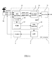
- FIG. 1 is a block diagram illustrating structure associated with an exemplary R/D converter according to one embodiment of the present invention
- FIG. 2 is a diagram illustrating phase angle and quadrant offsets including first, second, third, and fourth quadrants of an exemplary resolver
- FIG. 3 is a flow chart illustrating the operation of the exemplary R/D converter in accordance with a present embodiment.
- FIG. 1 is a block diagram illustrating an exemplary structure of R/D converter 1 including Digital Signal Processor (DSP) 2, lowpass filter (LPF) 3, and amplifier 4.
- DSP 2 calculates an angle associated with the position of the rotor axis of resolver 26, for example from a reference position, reference angle, or the like, based on a sine wave output and cosine wave output of resolver 26.
- DSP 2 further outputs an excitation sine wave to resolver 26 as follows.
- Counter 23 generates addresses for data ROM 24.
- Data ROM 24 stores the value of the sine wave sampled at the designated sampling frequency, and in accordance with the address from the counter 23, outputs the stored value using direct memory access (DMA) of data ROM 24 as would be understood to one of skill in the art.
- DMA direct memory access
- D/A converter 25 then converts the value from data ROM 24 and outputs the analog value.
- LPF 3 may be used to remove high frequency components, associated noise spikes or the like of the excitation sine wave.
- Serial port 13 is connected to DSP 2 and outputs data corresponding to the angle of the rotor axis of resolver 26. It will also be appreciated that serial port 13 may be used, for example by DSP 2, to receive input from an external source.
- DSP 2 includes A/D converter 21, axis angle calculator 22, counter 23, data ROM 24, and D/A converter 25.
- A/D converter 21 preferably has, for example, a resolution of 12 to 14 bits, and is used to convert the sine wave output and cosine wave output of resolver 26 from analog to digital.
- the tangent function is defined from 0° to 90°, and therefore, in order to develop the tangent result and transform or transpose it to a 360° space, the quadrant of the rotor axis of resolver 26 must be defined based, for example, on the polarity of sin ⁇ and cos ⁇ using DSP 2 as a discriminator, or the like, for judging or otherwise determining the present quadrant position of the rotor.
- axis angle calculator 22 determines a current position or current axis angle of the rotor axis of resolver 26 by checking the polarity of the sin ⁇ and cos ⁇ output from A/D converter 21. More specifically, the resolver excitation wave output is converted and the polarity of sin ⁇ and cos ⁇ is determined by comparing the polarity of the sine wave output and the cosine wave output of the resolver, and the quadrant of resolver rotor axis is determined.
- a complete rotational angle space - from 0° to 360° - associated with the rotor axis of resolver 26 is divided into four quadrants, with 0° to 90° set to be first quadrant 27, 90° to 180° set to be second quadrant 28, 180° to 270° set to be third quadrant 29, and 270° to 360° set to be fourth quadrant 30.
- the offset is set for each quadrant and by adding or subtracting the calculated angle ⁇ to or from an offset associated with each quadrant, axis angle calculator 22 may calculate the final angle of the rotor axis of resolver 26 as will be described in greater detail hereinafter.
- SDFS sampling frequency
- the above-described operation is carried out until the excitation state of the resolver is stabilized, for example, at the end of a known or otherwise predetermined time interval.
- the time for initial stabilization may be set by a timer (not shown in the drawing) as would be well known to one of ordinary skill in the art.
- the sine wave output and cosine wave output of the resolver are A/D converted with A/D converter 21 into a digitized sine wave and digitized cosine wave. It should be noted that an identical signal is used as a sampling clock for A/D conversion and D/A conversion, for example in connection with the output of the resolver excitation sine wave. It should further be noted that the sine wave output and cosine wave output of resolver 26 are A/D converted at the same time.
- tan ⁇ (A(sin ⁇ t) (sin ⁇ )) (A (sin ⁇ t)(cos ⁇ )) is calculated from the A/D converted value of the sine wave output and cosine wave output of resolver 26, A(sin ⁇ t)(sin ⁇ ) and A(sin ⁇ t) (cos ⁇ ) using axis angle calculator 22.
- ⁇ tan -1 ⁇ is calculated.
- the polarity of the A/D converted output of sin ⁇ and cos ⁇ is checked using axis angle calculator 22, and the current position, or current axis angle, of the rotor of resolver 26 is determined. If the polarity of the sin ⁇ and cos ⁇ of the A/D converted output indicates that rotor axis position of resolver 26 is in first quadrant 27 (0° to 90°), ⁇ is set to be the final rotation angle, or final angle, of the rotor axis of resolver 26 at 36. If the polarity indicates that the rotor axis position is in second quadrant 28 (90° to 180°), the value of 180° - ⁇ is set to be the final angle of the rotor axis at 37.
- the value of 180 ° + ⁇ is set to be the final angle of the rotor axis at 38. If the polarity indicates that the rotor axis position is in fourth quadrant 30 (270° to 360°), the value of 360 ° - ⁇ is set to be the final angle of the rotor axis at 39. Finally, at 40, the final rotation angle of the rotor axis of resolver 26 is output to serial port 13.
- the angle of the rotor axis of resolver 26 may be directly digitally calculated from the digitized sine wave and cosine wave, allowing high precision detection of the rotation angle of the rotor axis of resolver 26 particularly in operational environments characterized by a high rate of rotation of the rotor axis.
Landscapes
- Engineering & Computer Science (AREA)
- Theoretical Computer Science (AREA)
- Transmission And Conversion Of Sensor Element Output (AREA)
Abstract
Description
- The present invention relates to digital converters, and more particularly, to a converter and a method for digitizing the rotational output of a resolver.
- A resolver is a type of rotary transformer typically having two stator windings and one rotor winding on an axis or shaft. A resolver is used for determining the position of the shaft or axis of the rotor, with respect to a reference point, within a space of one complete revolution of the shaft or within a corresponding angular displacement space from 0° to 360°. The two stator windings are mechanically arranged such that their physical relation is shifted by a 90° angle. The physical spacing of the stator windings gives rise to a mathematical/electrical relation in that any signals induced in the stator windings from, for example, a rotor excitation signal, will be correspondingly shifted by 90° leading to the sine and cosine wave function relations assigned to the respective outputs of the stator windings. It will be appreciated that the degree of accuracy of the 90° physical relation based on, for example, accurate placement of stator windings, will affect the degree to which the outputs truly represent a sine and cosine relation. It is understood by those of ordinary skill in the art that the sine and cosine wave functions are mathematically related by a 90° shift.
- The amplification of a signal obtained by coupling with the stator windings is a function of the position of the resolver rotor axis and the relative position of the stator windings. Therefore, two types of output voltages (S3-S1, S4-S2) are modulated according to a sine wave function and a cosine wave function corresponding to the axis angle of the resolver rotor relative to the stator windings. The output voltage waveforms can be expressed in the following formulae (1) and (2).


- Proposals have been set forth for Resolver/Digital (R/D) converters in which, of the continuous output voltage signals S3-S1 and S4-S2, the signal with the smaller absolute value or magnitude is divided by the signal with the larger absolute value and, based on a resulting continuous signal associated with the quotient, the angle data is obtained. An example of such a proposed R/D converter may be seen, for example, in Japanese Unexamined Patent Application Publication S62-38302. Therein, tan θ and cot θ are calculated from output voltages S3-S4, S4-S2. At the same time, a digital code, or the like, for A(sin ωt) is determined from the output voltage S3-S1, the digital code result such as an index or the like, and the angle section of the resolver rotor axis obtained from the digital code result or index. As noted, one of either tan θ or cot θ may be used as a digital code, and angle data associated with resolver rotor axis angle θ and corresponding to the digital code or index and stored in advance in the table converter, is read and output.
- Problems arise however, since the proposed R/D converter mentioned above requires angle data, in a range of 0° to 360° corresponding to the digital codes or indexes determined from output voltages, to be stored in the table converter. When high precision is required, memory capacity must be increased since a greater number of angle data values must be stored. In addition, the continuous calculation of quotients, namely tan θ and cot θ, with a microcomputer involves a long calculation time, thereby making it less desirable or effective in an operational environment where quantities associated with a high rate of rotation of the resolver rotor axis are present.
- Accordingly, an object of the present invention is to provide an R/D converter and a method which is capable of high precision detection of the rotation angle of a resolver rotor axis.
- Another object of the invention is to provide an R/D converter and a method capable of working effectively in operational environments where a high rate of rotation of the resolver rotor axis is typical.
- Thus, the R/D converter of the present invention finds the angle of the resolver rotor axis based on a sine wave output and cosine wave output of the resolver. An A/D converter converts the sine wave output and cosine wave output of the resolver. A digital signal processor calculates the tangent value from the sine wave output and cosine wave output of the resolver digitized by the A/D converter, and directly digitally calculates the angle of the resolver rotor axis by calculating the arc tangent.
- In accordance with various exemplary embodiments, the R/D converter of the present invention includes a digital signal processor with a built-in A/D converter which converts the sine wave output and cosine wave output of the resolver into a digitized sine wave and digitized cosine wave respectively. The tangent value may then be calculated from the digitized sine wave and digitized cosine wave output. The arc tangent may then be calculated from the tangent through, for example, an inversion operation, and the angle of the resolver rotor axis is directly digitally calculated, allowing high precision detection of the rotation angle of the resolver rotor axis during high rates of rotation thereof.
- In addition, in accordance with various preferred modes and embodiments, the digital signal processor determines into which of four ninety degree quadrants associated with the rotational angle space (0° to 360°) of the resolver rotor axis the present axis position falls. The determination of the quadrant associated with the present position of the resolver rotor axis is based on the polarity of the sine wave output and cosine wave output of the resolver. The final angle of the resolver rotor axis is found by setting an offset value of the angle of the rotor axis based on the determined quadrant.
- Further, in accordance with various preferred modes and embodiments, values constituting a sampled sine wave with a designated sampling frequency may be stored in a memory of the digital signal processor, which may then output the stored values based on automatically generated addresses. Accordingly, the values from the memory are converted into an analog signal by the D/A converter and output as a sine wave for resolver excitation.
- Still further, in accordance with various preferred modes and embodiments, high frequency components may be removed by quantizing the resolver excitation sine wave output from the D/A converter.
- The accompanying figures, in which like reference numerals refer to identical or functionally similar elements throughout the separate views and which, together with the detailed description below, are incorporated in and form part of the specification, serve to further illustrate various embodiments and to explain various principles and advantages all in accordance with the present invention.
- FIG. 1 is a block diagram illustrating structure associated with an exemplary R/D converter according to one embodiment of the present invention;
- FIG. 2 is a diagram illustrating phase angle and quadrant offsets including first, second, third, and fourth quadrants of an exemplary resolver; and
- FIG. 3 is a flow chart illustrating the operation of the exemplary R/D converter in accordance with a present embodiment.
- Figure 1 is a block diagram illustrating an exemplary structure of R/
D converter 1 including Digital Signal Processor (DSP) 2, lowpass filter (LPF) 3, andamplifier 4. DSP 2 calculates an angle associated with the position of the rotor axis ofresolver 26, for example from a reference position, reference angle, or the like, based on a sine wave output and cosine wave output ofresolver 26. DSP 2 further outputs an excitation sine wave to resolver 26 as follows. -
Counter 23 generates addresses fordata ROM 24.Data ROM 24 stores the value of the sine wave sampled at the designated sampling frequency, and in accordance with the address from thecounter 23, outputs the stored value using direct memory access (DMA) ofdata ROM 24 as would be understood to one of skill in the art. D/Aconverter 25 then converts the value fromdata ROM 24 and outputs the analog value. By repeating the steps of access and conversion an analog signal may be generated and output to the above-mentionedLPF 3. Since the excitation sine wave is likely to contain quantizing noise associated with digital to analog conversion,LPF 3 may be used to remove high frequency components, associated noise spikes or the like of the excitation sine wave.Amplifier 4 amplifies the excitation sine wave fromLPF 3 after the high frequency components or the like have been removed and supplies the excitation sine wave to resolver 26.Serial port 13 is connected toDSP 2 and outputs data corresponding to the angle of the rotor axis ofresolver 26. It will also be appreciated thatserial port 13 may be used, for example by DSP 2, to receive input from an external source. - As shown in Figure 1, DSP 2 includes A/
D converter 21,axis angle calculator 22,counter 23,data ROM 24, and D/A converter 25. A/D converter 21 preferably has, for example, a resolution of 12 to 14 bits, and is used to convert the sine wave output and cosine wave output ofresolver 26 from analog to digital.Axis angle calculator 22 calculates tan θ = (A(sin ωt) (sin θ) ) / (A (sin ωt) (cos θ) ) from A(sin ωt) (sin θ) and A (sin ωt) (cos θ) output from A/D converter 21, and further calculates θ = tan-1 θ. However, the tangent function is defined from 0° to 90°, and therefore, in order to develop the tangent result and transform or transpose it to a 360° space, the quadrant of the rotor axis ofresolver 26 must be defined based, for example, on the polarity of sin θ and cos θ using DSP 2 as a discriminator, or the like, for judging or otherwise determining the present quadrant position of the rotor. - Therefore,
axis angle calculator 22 determines a current position or current axis angle of the rotor axis ofresolver 26 by checking the polarity of the sin θ and cos θ output from A/D converter 21. More specifically, the resolver excitation wave output is converted and the polarity of sin θ and cos θ is determined by comparing the polarity of the sine wave output and the cosine wave output of the resolver, and the quadrant of resolver rotor axis is determined. As shown in Figure 2, a complete rotational angle space - from 0° to 360° - associated with the rotor axis ofresolver 26, is divided into four quadrants, with 0° to 90° set to befirst quadrant 27, 90° to 180° set to besecond quadrant third quadrant fourth quadrant 30. The offset is set for each quadrant and by adding or subtracting the calculated angle θ to or from an offset associated with each quadrant,axis angle calculator 22 may calculate the final angle of the rotor axis ofresolver 26 as will be described in greater detail hereinafter. - Next, exemplary operation of R/
D converter 1 in accordance with the present invention as illustrated, for example, in the flow chart of Figure 3 is described. First, at 31, the sampling frequency (SDFS) of D/A converter 25 is set to 200 KHz, and an excitation sine wave of 200/20 = 10KHz is obtained by cyclically transmitting data values stored inROM 24 at successive addresses using circular addressing generated, for example, bycounter 23 as described herein above. After power is turned on, the above-described operation is carried out until the excitation state of the resolver is stabilized, for example, at the end of a known or otherwise predetermined time interval. The time for initial stabilization may be set by a timer (not shown in the drawing) as would be well known to one of ordinary skill in the art. - Next, at 32, the sine wave output and cosine wave output of the resolver are A/D converted with A/
D converter 21 into a digitized sine wave and digitized cosine wave. It should be noted that an identical signal is used as a sampling clock for A/D conversion and D/A conversion, for example in connection with the output of the resolver excitation sine wave. It should further be noted that the sine wave output and cosine wave output ofresolver 26 are A/D converted at the same time. - Next, at 33, tan θ = (A(sin ωt) (sin θ)) (A (sin ωt)(cos θ)) is calculated from the A/D converted value of the sine wave output and cosine wave output of
resolver 26, A(sin ωt)(sin θ) and A(sin ωt) (cos θ) usingaxis angle calculator 22. At 34, θ = tan-1 θ is calculated. - At 35, the polarity of the A/D converted output of sin θ and cos θ is checked using
axis angle calculator 22, and the current position, or current axis angle, of the rotor ofresolver 26 is determined. If the polarity of the sin θ and cos θ of the A/D converted output indicates that rotor axis position ofresolver 26 is in first quadrant 27 (0° to 90°), θ is set to be the final rotation angle, or final angle, of the rotor axis ofresolver 26 at 36. If the polarity indicates that the rotor axis position is in second quadrant 28 (90° to 180°), the value of 180° - θ is set to be the final angle of the rotor axis at 37. If the polarity indicates that the rotor axis position is in third quadrant 29 (180° to 270°), the value of 180° + θ is set to be the final angle of the rotor axis at 38. If the polarity indicates that the rotor axis position is in fourth quadrant 30 (270° to 360°), the value of 360° - θ is set to be the final angle of the rotor axis at 39. Finally, at 40, the final rotation angle of the rotor axis ofresolver 26 is output toserial port 13. - It should be noted that although the 12 to 14 bit resolution mentioned above in association with, for example, A/
D converter 21, is adequate for conversion, sufficient calculation precision can be obtained and maintained using at least 16 bit precision, or resolution, in calculations performed usingDSP 2, even for calculations for determining tan-1 θ . Given the unique characteristics of the tangent function, calculating tan θ using at least 16 bit precision and, for example, the relation sin θ/cos θ, the resolution of θ is not adversely affected particularly in the primary range of interest for initial calculations of θ of 0° to 90°. Therefore, high precision can be obtained in an R/D converter in accordance with the present invention, for example, using the above described calculations. - It should further be noted that in accordance with various exemplary embodiments, there is no need to synchronize the starting timing of A/D conversion to, for example, a specific phase of the excitation sine wave. An increase in sampling frequency of A/
D converter 21 is thereby allowed - to the extent that the increase is supportable by, for example, the processing capacity ofDSP 2. Consequently, accurate and efficient operation in an environment associated with a high rate of rotation of the rotor axis ofresolver 26, as described above, is possible. - Still further, as described above, because the sine wave output and cosine wave output of
resolver 26 are A/D converted by A/D converter 21 into digitized signals, the angle of the rotor axis ofresolver 26 may be directly digitally calculated from the digitized sine wave and cosine wave, allowing high precision detection of the rotation angle of the rotor axis ofresolver 26 particularly in operational environments characterized by a high rate of rotation of the rotor axis. - This disclosure is intended to explain how to fashion and use various embodiments in accordance with the invention rather than to limit the true, intended, and fair scope and spirit thereof. The foregoing description is not intended to be exhaustive or to limit the invention to the precise form disclosed. Modifications or variations are possible in light of the above teachings. The embodiments were chosen and described to provide the best illustration of the principles of the invention and its practical application, and to enable one of ordinary skill in the art to utilize the invention in various embodiments and with various modifications as are suited to the particular use contemplated. All such modifications and variations are within the scope of the invention as determined by the appended claims, as may be amended during the pendency of this application for patent, and all equivalents thereof, when interpreted in accordance with the breadth to which they are fairly, legally, and equitably entitled.
Claims (11)
- An R/D converter (1) for digitizing a rotational output of a resolver, the R/D converter (1) configured to find an angle of a rotor axis of the resolver (26) and comprising:a first converter (21) configured to convert a sine wave output and a cosine wave output of said resolver (26) to a digitized sine wave and digitized cosine wave, anda digital signal processor (2) including a calculator (22) configured to calculate a tangent from the digitized sine wave and the digitized cosine wave, and directly perform a digital calculation of the angle of said rotor axis of said resolver (26) by calculating an arc tangent from the calculated tangent.
- An R/D converter (1) in accordance with claim 1, wherein:said digital signal processor (2) further includes a discriminator (2) for determining to which one of four quadrants formed by dividing an angle space of said resolver into four, said rotor axis of said resolver (26) belongs, andsaid calculator (22) finds a final angle of said rotor axis of said resolver (26) by setting an offset value of the calculated angle of said rotor axis based on the one of four quadrants determined by said discriminator (2).
- An R/D converter (1) in accordance with Claim 1 or 2, wherein said digital signal processor (2) further includes:a memory (24) configured to store values of a sampled sine wave with a designated sampling frequency, and output said stored values based on an address automatically generated; anda second converter (25) configured to convert said stored values from said memory (24) into an analog signal and outputting said analog signal as a sine wave for providing excitation of said resolver (26).
- An R/D converter (1) in accordance with Claim 3, further comprising a filter (3) for removing a high frequency component generated by quantizing the sine wave for excitation.
- A method of digitizing a rotational output of a resolver and finding an angle of a rotor axis of the resolver (26), comprising the steps of:converting a sine wave output and a cosine wave output associated with the resolver (26) into a digitized sine wave output and a digitized cosine wave output respectively,calculating a tangent from the digitized sine wave output and the digitized cosine wave output, anddirectly calculating the angle of the rotor axis of the resolver (26) by digitally calculating an arc tangent from the calculated tangent.
- A method in accordance with claim 5, comprising the further steps of:determining to which one of four 90° quadrants the angle of the rotor axis belongs, the four quadrants formed by diving an angle space of 0° to 360° associated with the rotor axis by four, andfinding a final value of the angle of the rotor axis by setting an offset value of the angle of the rotor axis based on the determined one of the four 90° quadrants.
- A method in accordance with Claim 5 or 6, comprising the further steps of:storing values of a sampled sine wave with a designated sampling frequency,outputting the stored values based on an automatically generated address,converting the stored values output from the memory (24) into an analog signal, andoutputting the analog signal as a sine wave for providing excitation of the resolver (26).
- A method in accordance with Claim 7, comprising the further step of removing by filtering a high frequency component generated by quantizing the sine wave for excitation.
- A method in accordance with Claim 5, comprising the further steps of:determining a quadrant of the angle of the rotor axis, the quadrant determined from one of four 90° quadrants formed by dividing an angle space of 0° to 360° associated with the rotor axis by four, anddetermining a final value of the angle of the rotor axis by setting an offset value of the angle of said rotor axis based on the determined one of the four 90° quadrants.
- A method in accordance with Claim 5 or 9, comprising the further steps of:storing values of a sine wave sampled with a designated sampling frequency,outputting the stored values based on an automatically generated address,converting the stored values output from the memory (24) into an analog signal, andoutputting the analog signal as a sine wave for providing excitation of the resolver (26).
- A method in accordance with Claim 10, comprising the further step of removing by filtering a high frequency component generated by quantizing the sine wave for excitation.
Applications Claiming Priority (2)
| Application Number | Priority Date | Filing Date | Title |
|---|---|---|---|
| JP2003071581 | 2003-03-17 | ||
| JP2003071581A JP2004279231A (en) | 2003-03-17 | 2003-03-17 | R/d converter |
Publications (1)
| Publication Number | Publication Date |
|---|---|
| EP1460764A1 true EP1460764A1 (en) | 2004-09-22 |
Family
ID=32821280
Family Applications (1)
| Application Number | Title | Priority Date | Filing Date |
|---|---|---|---|
| EP04005701A Withdrawn EP1460764A1 (en) | 2003-03-17 | 2004-03-10 | Converter and method for digitizing an output of a resolver |
Country Status (3)
| Country | Link |
|---|---|
| US (1) | US7015840B2 (en) |
| EP (1) | EP1460764A1 (en) |
| JP (1) | JP2004279231A (en) |
Cited By (3)
| Publication number | Priority date | Publication date | Assignee | Title |
|---|---|---|---|---|
| CN104169687A (en) * | 2012-03-16 | 2014-11-26 | 三菱电机株式会社 | Angle detecting apparatus |
| CN106707892A (en) * | 2017-02-22 | 2017-05-24 | 西安应用光学研究所 | Double speed rotary transformer wiring automatic detection device suitable for photoelectric rotary table and double speed rotary transformer wiring automatic detection method thereof |
| CN112284427A (en) * | 2020-10-29 | 2021-01-29 | 中国航空工业集团公司洛阳电光设备研究所 | Method for high-speed conversion of angle signals of rotary transformer |
Families Citing this family (24)
| Publication number | Priority date | Publication date | Assignee | Title |
|---|---|---|---|---|
| JP4746427B2 (en) * | 2005-12-27 | 2011-08-10 | オリンパス株式会社 | Encoder interpolation device |
| US8201189B2 (en) * | 2005-12-30 | 2012-06-12 | Sap Ag | System and method for filtering components |
| US7205916B1 (en) * | 2006-01-27 | 2007-04-17 | Alliant Techsystems Inc. | Digital method and apparatus for resolving shaft position |
| US7248994B1 (en) | 2006-01-27 | 2007-07-24 | Alliant Techsystems Inc. | Digital method and apparatus for sensing position with a linear variable differential transformer |
| US8239154B2 (en) * | 2006-11-16 | 2012-08-07 | Continental Automotive Systems Us, Inc. | Method and apparatus for resolver compensation |
| US7469193B2 (en) | 2006-11-16 | 2008-12-23 | Continental Automotive Systems Us, Inc. | Method and apparatus for resolver compensation |
| US9068861B2 (en) * | 2012-08-24 | 2015-06-30 | Hamilton Sundstrand Corporation | Resolver interface |
| JP2015187560A (en) * | 2014-03-26 | 2015-10-29 | トヨタ自動車株式会社 | Resolver excitation circuit |
| US10402113B2 (en) | 2014-07-31 | 2019-09-03 | Hewlett Packard Enterprise Development Lp | Live migration of data |
| US10540109B2 (en) | 2014-09-02 | 2020-01-21 | Hewlett Packard Enterprise Development Lp | Serializing access to fault tolerant memory |
| WO2016064417A1 (en) | 2014-10-24 | 2016-04-28 | Hewlett Packard Enterprise Development Lp | End-to-end negative acknowledgment |
| JP6527704B2 (en) * | 2015-01-29 | 2019-06-05 | ルネサスエレクトロニクス株式会社 | Semiconductor device |
| US10664369B2 (en) | 2015-01-30 | 2020-05-26 | Hewlett Packard Enterprise Development Lp | Determine failed components in fault-tolerant memory |
| US10409681B2 (en) | 2015-01-30 | 2019-09-10 | Hewlett Packard Enterprise Development Lp | Non-idempotent primitives in fault-tolerant memory |
| WO2016122610A1 (en) | 2015-01-30 | 2016-08-04 | Hewlett Packard Enterprise Development Lp | Preventing data corruption and single point of failure in a fault-tolerant memory |
| US10402261B2 (en) | 2015-03-31 | 2019-09-03 | Hewlett Packard Enterprise Development Lp | Preventing data corruption and single point of failure in fault-tolerant memory fabrics |
| US10193634B2 (en) | 2016-09-19 | 2019-01-29 | Hewlett Packard Enterprise Development Lp | Optical driver circuits |
| US10389342B2 (en) * | 2017-06-28 | 2019-08-20 | Hewlett Packard Enterprise Development Lp | Comparator |
| JP7251751B2 (en) * | 2017-11-07 | 2023-04-04 | 株式会社松尾製作所 | Electrical angle acquisition system, electrical angle acquisition method, electrical angle acquisition program, electrical angle acquisition characteristic measurement system, electrical angle acquisition characteristic measurement method, and electrical angle acquisition characteristic measurement program |
| CN114234793B (en) * | 2020-09-09 | 2023-06-20 | 湖北工业大学 | A method for measuring the axis angle of a gyroscope |
| CN112152540B (en) * | 2020-09-29 | 2024-05-24 | 中国船舶集团有限公司第七二四研究所 | A method for calculating the full-angle position of a rotary transformer with single-winding feedback |
| US11567471B2 (en) | 2021-06-28 | 2023-01-31 | Stmicroelectronics (China) Investment Co. | Digital resolver decoder with hardware filter and rectifier |
| KR20240034843A (en) * | 2021-08-23 | 2024-03-14 | 파커-한니핀 코포레이션 | Systems and methods for controlling resolvers and motors with improved speed and direction monitoring |
| CN119483548A (en) * | 2022-01-10 | 2025-02-18 | 泉州昆泰芯微电子科技有限公司 | Angle extraction circuit, method and chip |
Citations (2)
| Publication number | Priority date | Publication date | Assignee | Title |
|---|---|---|---|---|
| EP0877489A2 (en) * | 1997-05-09 | 1998-11-11 | Kollmorgen Corporation | Direct resolver to digital converter |
| EP0978947A2 (en) * | 1998-08-05 | 2000-02-09 | Toyota Jidosha Kabushiki Kaisha | Resolver signal processing system |
Family Cites Families (11)
| Publication number | Priority date | Publication date | Assignee | Title |
|---|---|---|---|---|
| JPS5954917A (en) * | 1982-09-24 | 1984-03-29 | Toshiba Corp | Digital movement detecting device |
| JPS6238302A (en) | 1985-08-12 | 1987-02-19 | Kobe Steel Ltd | Angle detecting device |
| CA2014960C (en) * | 1990-04-19 | 1995-07-25 | Horst Arndt | Modular hearing aid |
| US5455498A (en) * | 1990-05-09 | 1995-10-03 | Omron Corporation | Angle of rotation detector |
| US5134404A (en) * | 1991-04-01 | 1992-07-28 | Aerotech, Inc. | Quadrature error correction |
| DE19545760C1 (en) * | 1995-12-07 | 1997-02-20 | Siemens Audiologische Technik | Digital hearing aid |
| DE19635229C2 (en) * | 1996-08-30 | 2001-04-26 | Siemens Audiologische Technik | Direction sensitive hearing aid |
| WO1998021553A1 (en) * | 1996-11-11 | 1998-05-22 | Fanuc Ltd. | Interpolation circuit of encoder |
| US6554303B2 (en) * | 1996-12-19 | 2003-04-29 | Valeo Schalter Und Sensoren Gmbh | Device for measuring a steering angle and for transferring signals between a steering column and a steering rod of a motor vehicle |
| US5949359A (en) * | 1997-05-09 | 1999-09-07 | Kollmorgen Corporation | Variable reluctance resolver to digital converter |
| JP2004301806A (en) * | 2003-04-01 | 2004-10-28 | Minebea Co Ltd | R/d converter |
-
2003
- 2003-03-17 JP JP2003071581A patent/JP2004279231A/en not_active Withdrawn
-
2004
- 2004-03-04 US US10/792,384 patent/US7015840B2/en not_active Expired - Fee Related
- 2004-03-10 EP EP04005701A patent/EP1460764A1/en not_active Withdrawn
Patent Citations (2)
| Publication number | Priority date | Publication date | Assignee | Title |
|---|---|---|---|---|
| EP0877489A2 (en) * | 1997-05-09 | 1998-11-11 | Kollmorgen Corporation | Direct resolver to digital converter |
| EP0978947A2 (en) * | 1998-08-05 | 2000-02-09 | Toyota Jidosha Kabushiki Kaisha | Resolver signal processing system |
Cited By (5)
| Publication number | Priority date | Publication date | Assignee | Title |
|---|---|---|---|---|
| CN104169687A (en) * | 2012-03-16 | 2014-11-26 | 三菱电机株式会社 | Angle detecting apparatus |
| CN104169687B (en) * | 2012-03-16 | 2016-08-24 | 三菱电机株式会社 | Angle detection device |
| CN106707892A (en) * | 2017-02-22 | 2017-05-24 | 西安应用光学研究所 | Double speed rotary transformer wiring automatic detection device suitable for photoelectric rotary table and double speed rotary transformer wiring automatic detection method thereof |
| CN106707892B (en) * | 2017-02-22 | 2019-03-29 | 西安应用光学研究所 | Two speed resolver wiring automatic detection device and method suitable for photoelectric turntable |
| CN112284427A (en) * | 2020-10-29 | 2021-01-29 | 中国航空工业集团公司洛阳电光设备研究所 | Method for high-speed conversion of angle signals of rotary transformer |
Also Published As
| Publication number | Publication date |
|---|---|
| JP2004279231A (en) | 2004-10-07 |
| US7015840B2 (en) | 2006-03-21 |
| US20040233078A1 (en) | 2004-11-25 |
Similar Documents
| Publication | Publication Date | Title |
|---|---|---|
| US7015840B2 (en) | Resolver/digital converter | |
| US6894629B2 (en) | Resolver/digital converter | |
| EP0978947B1 (en) | Resolver signal processing system | |
| US6018318A (en) | Method and apparatus for determining the phase angle in position transmitters with sinusoidal output signals | |
| JP5173962B2 (en) | Resolver / digital conversion apparatus and resolver / digital conversion method | |
| EP0877464A2 (en) | Variable reluctance resolver to digital converter | |
| US20050212511A1 (en) | Variable-reluctance resolver and rotational angle sensor using same | |
| EP0877489A2 (en) | Direct resolver to digital converter | |
| US6320524B1 (en) | R/D converter | |
| US5933106A (en) | Encoder signal analysis system for high-resolution position measurement | |
| US5034743A (en) | AC encoded signal to digital converter | |
| JP2008304249A (en) | Encoder signal processing apparatus and signal processing method thereof | |
| US5606515A (en) | Sensor conditioning circuitry for use with electrically excited transducers | |
| KR101012740B1 (en) | Resolver digital converter and position detecting apparatus | |
| CN111800638B (en) | Decoding method and decoding device | |
| US7119717B2 (en) | Encoder output divider and R/D converter | |
| WO2019017042A1 (en) | Rotation angle sensor-digital converter and rotation angle sensor-digital conversion method | |
| JPS6211113A (en) | Position detector | |
| RU2193794C2 (en) | Parameter-to-code converter | |
| EP1450148A1 (en) | Deviation Angle Detector | |
| JP2005031027A (en) | Angle detector | |
| JPH0212014A (en) | Detector and detection circuit of absolute position | |
| RU2265953C1 (en) | Device for transforming shaft rotation angle to code | |
| JP2938472B2 (en) | Rotation angle detector | |
| SU579642A1 (en) | Angle-to-code converter |
Legal Events
| Date | Code | Title | Description |
|---|---|---|---|
| PUAI | Public reference made under article 153(3) epc to a published international application that has entered the european phase |
Free format text: ORIGINAL CODE: 0009012 |
|
| AK | Designated contracting states |
Kind code of ref document: A1 Designated state(s): AT BE BG CH CY CZ DE DK EE ES FI FR GB GR HU IE IT LI LU MC NL PL PT RO SE SI SK TR |
|
| AX | Request for extension of the european patent |
Extension state: AL LT LV MK |
|
| 17P | Request for examination filed |
Effective date: 20050309 |
|
| AKX | Designation fees paid |
Designated state(s): AT BE BG CH CY CZ DE DK EE ES FI FR GB GR HU IE IT LI LU MC NL PL PT RO SE SI SK TR |
|
| STAA | Information on the status of an ep patent application or granted ep patent |
Free format text: STATUS: THE APPLICATION IS DEEMED TO BE WITHDRAWN |
|
| 18D | Application deemed to be withdrawn |
Effective date: 20060826 |