EP1460239B1 - Reed valve or reed valve assembly - Google Patents
Reed valve or reed valve assembly Download PDFInfo
- Publication number
- EP1460239B1 EP1460239B1 EP04006108A EP04006108A EP1460239B1 EP 1460239 B1 EP1460239 B1 EP 1460239B1 EP 04006108 A EP04006108 A EP 04006108A EP 04006108 A EP04006108 A EP 04006108A EP 1460239 B1 EP1460239 B1 EP 1460239B1
- Authority
- EP
- European Patent Office
- Prior art keywords
- reed
- valve
- rib
- reed valve
- support substrate
- Prior art date
- Legal status (The legal status is an assumption and is not a legal conclusion. Google has not performed a legal analysis and makes no representation as to the accuracy of the status listed.)
- Expired - Fee Related
Links
Images

Classifications
-
- F—MECHANICAL ENGINEERING; LIGHTING; HEATING; WEAPONS; BLASTING
- F16—ENGINEERING ELEMENTS AND UNITS; GENERAL MEASURES FOR PRODUCING AND MAINTAINING EFFECTIVE FUNCTIONING OF MACHINES OR INSTALLATIONS; THERMAL INSULATION IN GENERAL
- F16K—VALVES; TAPS; COCKS; ACTUATING-FLOATS; DEVICES FOR VENTING OR AERATING
- F16K15/00—Check valves
- F16K15/14—Check valves with flexible valve members
- F16K15/144—Check valves with flexible valve members the closure elements being fixed along all or a part of their periphery
-
- E—FIXED CONSTRUCTIONS
- E06—DOORS, WINDOWS, SHUTTERS, OR ROLLER BLINDS IN GENERAL; LADDERS
- E06B—FIXED OR MOVABLE CLOSURES FOR OPENINGS IN BUILDINGS, VEHICLES, FENCES OR LIKE ENCLOSURES IN GENERAL, e.g. DOORS, WINDOWS, BLINDS, GATES
- E06B3/00—Window sashes, door leaves, or like elements for closing wall or like openings; Layout of fixed or moving closures, e.g. windows in wall or like openings; Features of rigidly-mounted outer frames relating to the mounting of wing frames
- E06B3/54—Fixing of glass panes or like plates
- E06B3/58—Fixing of glass panes or like plates by means of borders, cleats, or the like
- E06B3/62—Fixing of glass panes or like plates by means of borders, cleats, or the like of rubber-like elastic cleats
- E06B3/6205—Fixing of glass panes or like plates by means of borders, cleats, or the like of rubber-like elastic cleats having on at least one lateral side no backing from a separate rigid glazing bead or other stiff part of the window frame
-
- F—MECHANICAL ENGINEERING; LIGHTING; HEATING; WEAPONS; BLASTING
- F01—MACHINES OR ENGINES IN GENERAL; ENGINE PLANTS IN GENERAL; STEAM ENGINES
- F01L—CYCLICALLY OPERATING VALVES FOR MACHINES OR ENGINES
- F01L3/00—Lift-valve, i.e. cut-off apparatus with closure members having at least a component of their opening and closing motion perpendicular to the closing faces; Parts or accessories thereof
- F01L3/20—Shapes or constructions of valve members, not provided for in preceding subgroups of this group
- F01L3/205—Reed valves
-
- F—MECHANICAL ENGINEERING; LIGHTING; HEATING; WEAPONS; BLASTING
- F01—MACHINES OR ENGINES IN GENERAL; ENGINE PLANTS IN GENERAL; STEAM ENGINES
- F01N—GAS-FLOW SILENCERS OR EXHAUST APPARATUS FOR MACHINES OR ENGINES IN GENERAL; GAS-FLOW SILENCERS OR EXHAUST APPARATUS FOR INTERNAL COMBUSTION ENGINES
- F01N3/00—Exhaust or silencing apparatus having means for purifying, rendering innocuous, or otherwise treating exhaust
- F01N3/08—Exhaust or silencing apparatus having means for purifying, rendering innocuous, or otherwise treating exhaust for rendering innocuous
- F01N3/10—Exhaust or silencing apparatus having means for purifying, rendering innocuous, or otherwise treating exhaust for rendering innocuous by thermal or catalytic conversion of noxious components of exhaust
- F01N3/24—Exhaust or silencing apparatus having means for purifying, rendering innocuous, or otherwise treating exhaust for rendering innocuous by thermal or catalytic conversion of noxious components of exhaust characterised by constructional aspects of converting apparatus
- F01N3/30—Arrangements for supply of additional air
-
- F—MECHANICAL ENGINEERING; LIGHTING; HEATING; WEAPONS; BLASTING
- F16—ENGINEERING ELEMENTS AND UNITS; GENERAL MEASURES FOR PRODUCING AND MAINTAINING EFFECTIVE FUNCTIONING OF MACHINES OR INSTALLATIONS; THERMAL INSULATION IN GENERAL
- F16K—VALVES; TAPS; COCKS; ACTUATING-FLOATS; DEVICES FOR VENTING OR AERATING
- F16K15/00—Check valves
- F16K15/14—Check valves with flexible valve members
- F16K15/1402—Check valves with flexible valve members having an integral flexible member cooperating with a plurality of seating surfaces
-
- F—MECHANICAL ENGINEERING; LIGHTING; HEATING; WEAPONS; BLASTING
- F16—ENGINEERING ELEMENTS AND UNITS; GENERAL MEASURES FOR PRODUCING AND MAINTAINING EFFECTIVE FUNCTIONING OF MACHINES OR INSTALLATIONS; THERMAL INSULATION IN GENERAL
- F16K—VALVES; TAPS; COCKS; ACTUATING-FLOATS; DEVICES FOR VENTING OR AERATING
- F16K15/00—Check valves
- F16K15/14—Check valves with flexible valve members
- F16K15/16—Check valves with flexible valve members with tongue-shaped laminae
- F16K15/162—Check valves with flexible valve members with tongue-shaped laminae with limit stop
-
- E—FIXED CONSTRUCTIONS
- E06—DOORS, WINDOWS, SHUTTERS, OR ROLLER BLINDS IN GENERAL; LADDERS
- E06B—FIXED OR MOVABLE CLOSURES FOR OPENINGS IN BUILDINGS, VEHICLES, FENCES OR LIKE ENCLOSURES IN GENERAL, e.g. DOORS, WINDOWS, BLINDS, GATES
- E06B3/00—Window sashes, door leaves, or like elements for closing wall or like openings; Layout of fixed or moving closures, e.g. windows in wall or like openings; Features of rigidly-mounted outer frames relating to the mounting of wing frames
- E06B3/54—Fixing of glass panes or like plates
- E06B3/5454—Fixing of glass panes or like plates inside U-shaped section members
- E06B2003/5472—Fixing of glass panes or like plates inside U-shaped section members in an at least partly preassembled frame by introducing it through a slot in one of the frame members or inserting the pane before completing the frame
-
- E—FIXED CONSTRUCTIONS
- E06—DOORS, WINDOWS, SHUTTERS, OR ROLLER BLINDS IN GENERAL; LADDERS
- E06B—FIXED OR MOVABLE CLOSURES FOR OPENINGS IN BUILDINGS, VEHICLES, FENCES OR LIKE ENCLOSURES IN GENERAL, e.g. DOORS, WINDOWS, BLINDS, GATES
- E06B3/00—Window sashes, door leaves, or like elements for closing wall or like openings; Layout of fixed or moving closures, e.g. windows in wall or like openings; Features of rigidly-mounted outer frames relating to the mounting of wing frames
- E06B3/54—Fixing of glass panes or like plates
- E06B3/58—Fixing of glass panes or like plates by means of borders, cleats, or the like
- E06B3/62—Fixing of glass panes or like plates by means of borders, cleats, or the like of rubber-like elastic cleats
- E06B2003/6217—Fixing of glass panes or like plates by means of borders, cleats, or the like of rubber-like elastic cleats with specific fixing means
- E06B2003/6223—Fixing of glass panes or like plates by means of borders, cleats, or the like of rubber-like elastic cleats with specific fixing means with protruding parts anchored in grooves
-
- F—MECHANICAL ENGINEERING; LIGHTING; HEATING; WEAPONS; BLASTING
- F01—MACHINES OR ENGINES IN GENERAL; ENGINE PLANTS IN GENERAL; STEAM ENGINES
- F01L—CYCLICALLY OPERATING VALVES FOR MACHINES OR ENGINES
- F01L2301/00—Using particular materials
-
- Y—GENERAL TAGGING OF NEW TECHNOLOGICAL DEVELOPMENTS; GENERAL TAGGING OF CROSS-SECTIONAL TECHNOLOGIES SPANNING OVER SEVERAL SECTIONS OF THE IPC; TECHNICAL SUBJECTS COVERED BY FORMER USPC CROSS-REFERENCE ART COLLECTIONS [XRACs] AND DIGESTS
- Y02—TECHNOLOGIES OR APPLICATIONS FOR MITIGATION OR ADAPTATION AGAINST CLIMATE CHANGE
- Y02T—CLIMATE CHANGE MITIGATION TECHNOLOGIES RELATED TO TRANSPORTATION
- Y02T10/00—Road transport of goods or passengers
- Y02T10/10—Internal combustion engine [ICE] based vehicles
- Y02T10/12—Improving ICE efficiencies
-
- Y—GENERAL TAGGING OF NEW TECHNOLOGICAL DEVELOPMENTS; GENERAL TAGGING OF CROSS-SECTIONAL TECHNOLOGIES SPANNING OVER SEVERAL SECTIONS OF THE IPC; TECHNICAL SUBJECTS COVERED BY FORMER USPC CROSS-REFERENCE ART COLLECTIONS [XRACs] AND DIGESTS
- Y10—TECHNICAL SUBJECTS COVERED BY FORMER USPC
- Y10T—TECHNICAL SUBJECTS COVERED BY FORMER US CLASSIFICATION
- Y10T137/00—Fluid handling
- Y10T137/7722—Line condition change responsive valves
- Y10T137/7837—Direct response valves [i.e., check valve type]
- Y10T137/7838—Plural
- Y10T137/7839—Dividing and recombining in a single flow path
- Y10T137/784—Integral resilient member forms plural valves
-
- Y—GENERAL TAGGING OF NEW TECHNOLOGICAL DEVELOPMENTS; GENERAL TAGGING OF CROSS-SECTIONAL TECHNOLOGIES SPANNING OVER SEVERAL SECTIONS OF THE IPC; TECHNICAL SUBJECTS COVERED BY FORMER USPC CROSS-REFERENCE ART COLLECTIONS [XRACs] AND DIGESTS
- Y10—TECHNICAL SUBJECTS COVERED BY FORMER USPC
- Y10T—TECHNICAL SUBJECTS COVERED BY FORMER US CLASSIFICATION
- Y10T137/00—Fluid handling
- Y10T137/7722—Line condition change responsive valves
- Y10T137/7837—Direct response valves [i.e., check valve type]
- Y10T137/7879—Resilient material valve
- Y10T137/7888—With valve member flexing about securement
- Y10T137/7891—Flap or reed
- Y10T137/7892—With stop
Definitions
- the present invention relates to a reed valve or reed valve assembly suitable for supplying air to an intake system or exhaust system of an internal combustion engine (engine), and particularly to a reed valve or reed valve assembly used to supply secondary air to an exhaust port of an engine.
- a secondary air supply port of an engine used as one gas regulating counter-measure is used to supply air from an air cleaner to an exhaust port to recombust an uncombusted component contained in exhaust gas.
- air from the air cleaner is supplied to the exhaust port, but a reed valve is provided at some point in the secondary air supply unit so that exhaust gas from the exhaust port does not flow back to the air cleaner.
- air is supplied from the air cleaner to the exhaust port by taking advantage of a pressure difference between above and below the reed valve arising in the exhaust port as a result of pulsation of the exhaust gas.
- the reed valve when the pressure at the exhaust port side is low, the reed valve is opened to supply air from the air cleaner to the exhaust port, while when the pressure at the exhaust port side is high the reed valve is closed to prevent exhaust gas flowing back to the air cleaner.
- a structure is known haying a valve hole in a central part of a plate shaped support substrate, passing through in the plate thickness direction, with a reed arranged so as to cover this valve hole, with one end in the longitudinal direction of the reed fixed to a support base (refer to JP-2002 - 250233 for example), and in the case of using a secondary air supply unit the reed valve is arranged so that a surface to which the reed is attached is positioned at an exhaust port side.
- Document US-A-4 083184 discloses a reed valve according to the preamble part of claim 1.
- the generic reed valve comprises a support substrate disposed within a secondary air supply passage orthogonal to the direction of the flow path.
- the support substrate has two valve holes of equal shape formed therein side by side. Each valve hole is covered by a respective flexible reed, each having one end fixed to the support substrate in a longitudinal direction. At said end, the two reeds are formed integrally with each other.
- a reed valve assembly according to the preamble part of claim 4 is disclosed in document US-A-4 387 565.
- This reed valve assembly comprises a reed valve cover forming an air intake pipe. Formed inside the cover is a rib which acts to divide the flow path of intake air into two separate flow paths in order to simultaneously supply secondary intake air to two separate exhaust ports of two cylinders of an engine. After being separated by the rib, each flow path passes a reed valve that is formed by a valve hole covered by a reed.
- plate thickness provided in the case of applying excessive pressure to the reed valve such as when there is a rapid transition from a low pressure state at the exhaust port side to a high pressure state, must be thick, but on the other hand, to increase followability of the reed valve the plate thickness must be thin, and that compatibility is a problem.
- the present invention has been conceived in view of the above-described problem, and an object of the invention is to provide a reed valve or a reed valve assembly having high followability even with a reed of thin plate thickness, and with a structure that can withstand excessive pressure.
- a reed valve of the present invention comprises a plate shaped support substrate with a valve hole formed in a central section passing through in a plate thickness direction, and a flexible plate-shaped reed covering the valve hole at one surface of the support substrate and having one end in a longitudinal direction that is fixed to the support substrate.
- the support substrate has a rib extending along a center line in a longitudinal direction of the inside of the valve hole, to divide the valve hole into two spaces, and a surface of the rib opposite to the reed is positioned on substantially the same plane as a surface of the support substrate to which the rib is attached, or inside the valve hole, and is adjacent to the reed.
- the rib has a grooved section formed in a surface opposite to the reed penetrating in a width direction of the rib, and the grooved section passes through a space inside the valve hole divided by the rib.
- the grooved section prefferably be formed at a part of the rib that is close to an end opposite to an end to which the reed is fixed.
- a surface of the rib opposite to a surface facing the reed is formed having a V-shaped cross section projecting outwards.
- a reed valve assembly of the present invention comprises a reed valve, provided with a plate shaped support substrate with a valve hole formed in a central section passing through in a plate thickness direction, and a flexible plate-shaped reed covering the valve hole at one surface of the support substrate and having one end in a longitudinal direction that is fixed to the support substrate, and a reed valve cover forming an air intake pipe for supplying air for passing the reed vale, attached so as to cover a surface opposite to a surface to which the reed is attached.
- a rib extending from a surface facing the valve hole to the valve hole side is formed at an inner side surface of the reed valve cover and a surface of the rib opposite to the read is adjacent to the reed.
- the above described reed valve or reed valve assembly preferably have the reed valve attached inside a secondary air supply passage for supplying secondary air from an intake unit (for example, the air cleaner 19 of the embodiments) of an internal combustion engine (for example, the engine E of the embodiments) to an exhaust port, with a surface to which the reed is attached facing towards the exhaust port side, used in such a way that exhaust gas inside the exhaust port does not flow back to the intake device through the secondary air supply passage.
- an intake unit for example, the air cleaner 19 of the embodiments
- an internal combustion engine for example, the engine E of the embodiments
- the reed valve of the present invention has the above described structure, since the reed is pressed against the rib and held, even if excessive pressure is applied to the reed from a surface side where the reed of the reed valve is arranged, it is possible to make the reed plate thickness thin, and to increase followability of the reed valve. Also, it is possible to make seating noise of the reed due to the rib low.
- the reed valve assembly of the present invention since the reed is held by the rib, even if excessive pressure is applied to the reed from a surface side where the reed of the reed valve is arranged, it is possible to make the reed plate thickness thin, and to increase followability of the reed valve.
- the reed valve cover When the reed valve cover is attached, by having a structure where there is a specified distance between the reed and the rib, the gas flow is not disturbed by the rib and the reed can be held.
- the reed valve or reed valve assembly of the present invention inside a secondary gas supply passage of an internal combustion engine, when secondary gas is supplied and uncombusted components contained in exhaust gas inside the exhaust port are combusted to raise the pressure inside the exhaust port rapidly, even if excessive pressure is applied to the reed, the reed is held by the rib which means that it is possible to make the plate thickness of the reed thin, and it is thus possible to increase followability of the reed valve.
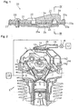
- the engine E is made up of a cylinder block 1, a cylinder head 2 and a cylinder head cover 3.
- An intake port 6 and an exhaust port 7 respectively communicate, via an intake opening and an exhaust opening, with a combustion chamber 5 formed by the cylinder block 1, cylinder head 2 and piston 4 positioned inside a cylinder of the cylinder block 1.
- a mushroom-shaped intake valve 8 and a mushroom shaped exhaust valve 9 have one end supported on a retainer attached to a valve stem, and another end urged in a direction normally closing the respective intake opening and exhaust opening by valve springs 10, 11 supported in the cylinder head 12.
- the intake valve 8 and exhaust valve 9 are operated to open and close by a cam mechanism constituted by cams and rocker arms etc. Air that has been purified by an air filter 19 is supplied from the intake port 6 together with fuel to the combustion chamber 5 and combusted, and exhaust has is discharged to the outside by the exhaust port 7.
- a valve housing chamber 13 is formed in an upper part of the cylinder head cover 3, and an upper passage 16a is formed by extending the inside of the cylinder head cover 3 downwards from the bottom of this valve housing chamber 13.
- a lower passage 16b is formed in the cylinder head 2 linking from an upper part to the intake port 6, and when the cylinder head cover 3 is attached to the cylinder head 2 the upper passage 16a and lower passage 16b are connected to form a secondary air supply passage 16.
- a reed valve 20 is attached to an upper part of the valve housing chamber 13, and a reed of the reed valve 20 at this time is arranged so as to be positioned at the valve housing chamber 13 side (the reed valve 20 will be described in detail later).
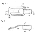
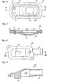
- a reed valve cover 14 as shown in Fig. 5 and Fig. 6 is then attached to an upper part of the reed valve 20, this reed valve cover 14 having an inner space 14b opening downwards and an air intake pipe 15 being formed extending in a substantially horizontal direction to connect to the inner space 14b.
- the reed valve cover 14 is linked to the cylinder head cover 3 by fitting bolts into attachment sections 14a, 14a formed in the reed valve cover 14 and attachment sections 13a, 13a formed in the cylinder head cover 3.
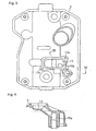
- This reed valve 20 has a plate shaped support substrate 21 formed in a substantially flat rectangular shape using a metal such as aluminum.
- a valve hole 22 is formed passing through a central part of this support substrate 21 in a plate thickness direction.
- a thin film gasket section 23 formed using a flexible body of rubber or the like is formed on both upper and lower surface and an outer surface of the outer section of the support substrate 21.
- annular projections 23a are formed on both upper and lower surfaces and an outer surface of this gasket section 23, and when this reed valve 20 is attached to the engine E these annular projections 23a contact the valve housing chamber 13 and the reed valve cover 14 to abut and hold the reed valve 20, and form a seal so that gas does not flow out from the abutted and held sections. Also, using this gasket section 23 vibration of the reed valve 20 being transmitted to the engine E is reduced.
- a reed 24 formed in a substantially rectangular flat plate shape capable of opening and closing depending on pressure of gas passing through the valve hole 22 is arranged on one surface of this support substrate 21 (the lower surface in Fig. 1) so as to bock off the valve hole 22, and also a stopper 25 for regulating an open position of the reed 24 is attached to a lower surface side of the reed 24.
- the reed 24 and one end of the stopper 25 in a longitudinal direction are fixed in a cantilever shape using a linking member inserted from above the support substrate 21 (a surface opposite to the surface the reed 24 is attached to). It is possible to use a screw or rivet as the linking member 28.
- the reed 24 enables flow of gas from above the valve hole 22 to below (this direction will be called “forward” in the rest of the description), and prevents flow in the opposite direction (this direction will be called “backwards” in the rest of the description), and is formed of a flexible thin plate of metal or resin.
- the stopper 25 is formed from a rigid metal or the like, and sections of the stopper 25 other than support ends are formed so as to be separated from the support substrate 21, and in particular, so as to be as far apart as possible from the lower surface of the support substrate 21 at a central part of the valve hole 22 in the longitudinal direction, and formed having a downwardly convex shape. In this way, as shown by the dotted line in Fig.
- a lift amount of the reed 24 (amount of separation from the lower surface of the support substrate 21) is regulated by the stopper 25, and a position of maximum possible separation from the lower surface of the support substrate 21 as a result of the opening and closing operation of the reed 24 is regulated so as to become a central section of the valve hole 22 I the longitudinal direction.
- an amount of lift of a tip section positioned at the free end side of the reed 17 is regulated using the stopper 25 formed in this way so as to be made small.
- a punched hole 25a passing through in a plate thickness direction and having a smaller area than the valve hole 22 is formed in a section of the stopper 25 opposite to the valve hole 22.
- the support substrate 21 is formed with a rib 26 extending along a center line in the longitudinal direction of the valve hole 22 for dividing the inside of the valve hole 22 into two spaces 22a and 22b.
- the above described gasket section 23 is formed extending to the lower surface (reed 24 side surface) of this rib 26, and a lower surface of the rib 26 containing the gasket section 23 is positioned on substantially the same plane as a peripheral section (here, since it is seated when the reed 24 is closed, it will be called a seating surface) of the valve hole 22 at the lower surface of the support substrate 21 or inside the valve hole 22.
- a grooved section 27 passing through a width direction side surface is formed in a reed 24 side surface of the rib 26, and using this grooved section 27 the valve hole 22 is connected to the two spaces 22a and 22b divided by the rib 26.
- a surface of the rib 26 opposite to the reed 24 has a roofed shape projecting outwards, and is V-shaped in cross section.
- a rib 26 is formed in the support substrate 21 constituting the reed valve 20 so that the reed 24 is not forced into the valve hole 22, but it is also possible to form this rib is at a reed valve case side and to have a reed valve assembly comprising the reed valve and a reed valve case. Implementation of a reed valve assembly will be described in the following using Fig. 10 to Fig. 13.
- the reed valve 30 also has a plate-shaped support substrate 31 formed in a flat substantially rectangular shape using metal such as aluminum, and a valve hole 32 is formed in a substantially central part of this support substrate 31, passing through in a plate thickness direction. Also, a thin film first gasket section 33 made of a flexible material such as rubber is formed on both upper and lower surface of the outside of this support substrate 31 and an outer surface.
- Projections that are the same as the annular projections formed on the gasket section 23 in the description of the reed valve 20 above are formed at three places on this first gasket section 33, namely both the upper and lower surface and on the outer surface, and the effects and operation when attached to the engine are also the same.
- a second gasket section 34 surrounding this valve hole 32 is formed in one surface (the lower surface in Fig. 11) of the support substrate 31, and this second gasket section 34 constitutes a seating surface of the reed 35.
- the reed 35 is then disposed so as to block off the valve hole 32 from a surface at the side where the second gasket section 34 is formed, and a stopper 36 is also arranged at a lower surface side of the reed 35.
- the reed 35 and the stopper 36 are attached with a linking member 37, in the same way as the reed valve 20 described above, and a punched hole 36a having a smaller area than the valve hole 32 is formed in a part of the stopper 36 that is opposite to the valve hole 32.
- the reed valve 30 having this structure also, if gas pressure in a forward direction is applied from an upper surface side (a surface side opposite to the surface where the reed 35 is arranged) of the reed valve 30, the reed 35 is opened (the state of the reed 35 shown by a dotted line in Fig. 11) and gas flows through the valve hole 32. Conversely, if gas pressure is applied in a backward direction from the lower surface side of the reed valve 30, backward gas flow is prevented.
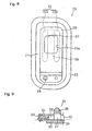
- the reed valve cover 40 is also the same as the reed valve cover 14 described above, having a space 40b inside opening downward and with an air intake pipe 41 formed so as to communicate with this inner space 40b.
- a rib 42 is then formed extending downwards from an upper surface of the inner space 40b (namely a surface opposite to the valve hole 32 when the reed valve case 40 is attached to the reed valve 30).
- a lower end of this rib 42 is positioned further down than a lower surface of the reed valve case 40, and the area of the lower surface of the rib 42 is smaller than the area of the valve hole 32.
- a reed valve assembly that is a combination of the reed valve 30 having the above described structure and the reed valve cover 40, even if gas pressure in a backward direction is applied from a surface where the reed 35 is positioned, since the reed 35 is pressed against and supported on the rib 42 the reed 35 is not forced into the valve hole 32 and it is possible to prevent damage to the reed valve 30. Also, because there is a specified gap between the lower surface of the rib 42 and the upper surface of the reed 35, when gas flows in a forward direction this rib 42 does not interfere with the gas flow.
- the method of the reed valve 30 and the reed valve cover 40 (reed valve assembly) to the cylinder head cover 3 is the same s for the reed valve 20 and the reed valve cover 14 described above.
- a rib 26, 42 on a reed valve cover 40 covering the reed valve 20 or reed valve assembly 30 and making the rib close to the reed 24, 35, even if excessive gas pressure is applied to the reed valve 20, 30 in a backward direction, since the reed 24, 35 is held by the rib 26, 42 it is possible to make the plate thickness of the reed 24, 35 thin, and it is therefore possible to increase the followability of the reed valve 20, 30.
- the reed valve 20 or reed valve assembly 30 of the present invention is used in a secondary air supply unit (secondary air supply passage 16) of an engine E, by supplying secondary air and combusting non-combusted components contained in exhaust gas inside an exhaust port even if pressure inside the exhaust port rises abruptly the reed is not forced into the valve hole because the reed is pressed against and supported on this rib. Also, by making the plate thickness of the reed 24, 35 thin, it is also possible to have good followability for secondary air supply.
- the invention provides a reed valve or reed valve assembly having thin reed plate thickness and a structure that can withstand excessive pressure and has high followability.
- a reed valve 20 comprises a plate shaped support substrate 21 with a valve hole 22 formed in a central section passing through in a plate thickness direction, and a flexible plate-shaped reed 24 covering the valve hole 22 at one surface of the support substrate 21 and having one end in a longitudinal direction that is fixed to the support substrate, and the support substrate 21 has a rib 27 extending along a center line in a longitudinal direction of the inside of the valve hole 22, to divide the valve hole 22 into two spaces (22a, 22b).
- a surface of the rib opposite to the reed is positioned on substantially the same plane as a surface of the support substrate to which the rib is attached, or inside the valve hole, and is adjacent to the reed.
Description
The invention provides a reed valve or reed valve assembly having thin reed plate thickness and a structure that can withstand excessive pressure and has high followability.
Claims (6)
- Reed valve (20) provided with a plate shaped support substrate (21) with a valve hole (22) formed in a central section passing through in a plate thickness direction, and a flexible plate-shaped reed (24) covering the valve hole (22) at one surface of the support substrate (21) and having one end in a longitudinal direction that is fixed to the support substrate (21), wherein the support substrate (21) has a rib (26) extending along a center line in a longitudinal direction of the inside of the valve hole (22), to divide the valve hole (22) into two spaces (22a, 22b), and wherein a surface of the rib (26) opposite to the reed (24) is positioned on substantially the same plane as a surface of the support base (21) to which the rib (26) is attached, or inside the valve hole (22), and is adjacent to the reed (24),
characterized in that the rib (26) has a grooved section formed in a surface opposite to the reed (24) penetrating in a width direction of the rib (26), wherein the grooved section passes through a space inside the valve hole (22) divided by the rib (26). - Reed valve (20) of claim 1, characterized in that the grooved section is formed at a part of the rib (26) that is close to an end opposite to an end to which the reed (24) is fixed.
- Reed valve (20) of claim 1 or claim 2, characterized in that a surface of the rib (26) opposite to a surface facing the reed (24) is formed having a V-shaped cross section projecting outwards.
- Reed valve assembly (30), comprising a reed valve (30), provided with a plate shaped support substrate (31) with a valve hole (32) formed in a central section passing through in a plate thickness direction, and a flexible plate-shaped reed (35) covering the valve hole (32) at one surface of the support substrate (31) and having one end in a longitudinal direction that is fixed to the support substrate (31), and a reed valve cover (40) forming an air intake pipe (41) for supplying air for passing the reed valve (30), attached so as to cover a surface opposite to a surface to which the reed (35) is attached, wherein a rib (42) extending from a surface facing the valve hole (32) to the valve hole side is formed at an inner side surface of the reed valve cover (40), characterized in that a surface of the rib (42) opposite to the reed (35) is adjacent to the reed (35).
- Reed valve assembly (30) of claim 4, characterized in that, when the reed valve cover (40) has been attached to the reed valve (30), there is a specified gap between the rib (42) and the reed (35).
- Internal combustion engine with a reed valve (20) of any one of claim 1 to claim 3 or with the reed valve assembly (30) of claim 4 or claim 5, characterized in that the reed valve (20; 30) is attached inside a secondary air supply passage (16) for supplying secondary air from an intake unit (19, 6, 8) of the internal combustion engine (6) to an exhaust port (7), with a surface to which the reed (24; 35) is attached facing towards the exhaust port (7) side, used in such a way that exhaust gas inside the exhaust port (7) does not flow back to the intake device (19, 6, 8) through the secondary air supply passage (16).
Applications Claiming Priority (4)
| Application Number | Priority Date | Filing Date | Title |
|---|---|---|---|
| JP2003077567 | 2003-03-20 | ||
| JP2003077567 | 2003-03-20 | ||
| JP2004005386 | 2004-01-13 | ||
| JP2004005386A JP4497936B2 (en) | 2003-03-20 | 2004-01-13 | Reed valve |
Publications (2)
| Publication Number | Publication Date |
|---|---|
| EP1460239A1 EP1460239A1 (en) | 2004-09-22 |
| EP1460239B1 true EP1460239B1 (en) | 2005-10-26 |
Family
ID=32829017
Family Applications (1)
| Application Number | Title | Priority Date | Filing Date |
|---|---|---|---|
| EP04006108A Expired - Fee Related EP1460239B1 (en) | 2003-03-20 | 2004-03-15 | Reed valve or reed valve assembly |
Country Status (7)
| Country | Link |
|---|---|
| US (1) | US7201189B2 (en) |
| EP (1) | EP1460239B1 (en) |
| JP (1) | JP4497936B2 (en) |
| KR (1) | KR100584231B1 (en) |
| CN (1) | CN1283945C (en) |
| CA (1) | CA2460619C (en) |
| DE (1) | DE602004000151T2 (en) |
Families Citing this family (16)
| Publication number | Priority date | Publication date | Assignee | Title |
|---|---|---|---|---|
| JP2006057465A (en) * | 2004-08-17 | 2006-03-02 | Yamaha Motor Co Ltd | Engine |
| US7866961B2 (en) * | 2004-12-06 | 2011-01-11 | Daikin Industries, Ltd. | Compressor with discharge valve arrangement |
| DE112009001704A5 (en) * | 2008-08-21 | 2011-09-29 | Ixetic Mac Gmbh | reciprocating engine |
| JP5559720B2 (en) * | 2010-03-31 | 2014-07-23 | 株式会社豊田自動織機 | Compressor |
| JP5212432B2 (en) * | 2010-07-16 | 2013-06-19 | 株式会社デンソー | Reed valve |
| CN101949379B (en) * | 2010-09-20 | 2012-11-07 | 亚新科美联(廊坊)制动系统有限公司 | Vehicle air compressor intake and exhaust component capable of effectively reducing noise |
| JP5916358B2 (en) * | 2011-11-30 | 2016-05-11 | ダイハツ工業株式会社 | Reed valve structure |
| JP6039073B2 (en) * | 2013-06-24 | 2016-12-07 | 株式会社日立産機システム | Fluid machinery |
| BR102014002144A2 (en) * | 2014-01-28 | 2015-10-27 | Whirlpool Sa | reciprocating compressor stop and valve arrangement |
| CN105781680A (en) * | 2016-05-17 | 2016-07-20 | 上海天纳克排气系统有限公司 | Leaf spring type control valve of exhaust system |
| JP6897212B2 (en) * | 2017-03-24 | 2021-06-30 | スズキ株式会社 | Engine exhaust purification device and vehicle |
| JP6859818B2 (en) * | 2017-04-10 | 2021-04-14 | スズキ株式会社 | Secondary air injection device |
| JP6714647B2 (en) | 2018-07-06 | 2020-06-24 | 本田技研工業株式会社 | Secondary air introduction device for internal combustion engine for saddle type vehicle |
| CN210317504U (en) * | 2019-06-21 | 2020-04-14 | 北京致行慕远科技有限公司 | Cylinder and all-terrain vehicle with same |
| FR3101111B1 (en) * | 2019-09-24 | 2022-04-08 | Renault Sas | Exhaust air injection device |
| JP2021165558A (en) * | 2020-04-06 | 2021-10-14 | 株式会社ミクニ | Reed valve |
Family Cites Families (12)
| Publication number | Priority date | Publication date | Assignee | Title |
|---|---|---|---|---|
| US3968925A (en) * | 1975-05-12 | 1976-07-13 | Plastronics, Inc. | Anti-reflux valve |
| JPS5445224Y2 (en) * | 1975-08-18 | 1979-12-25 | ||
| JPS5340118U (en) * | 1976-09-13 | 1978-04-07 | ||
| JPS5399612U (en) * | 1977-01-17 | 1978-08-12 | ||
| JPS6032340Y2 (en) * | 1980-03-24 | 1985-09-27 | 本田技研工業株式会社 | Exhaust purification device for two-cylinder internal combustion engines for motorcycles |
| JPS57144281U (en) * | 1981-03-06 | 1982-09-10 | ||
| FR2578943B1 (en) * | 1985-03-14 | 1987-09-25 | Commissariat Energie Atomique | AUTOMATIC NON-RETURN VALVE |
| JPH0350263Y2 (en) * | 1985-07-03 | 1991-10-28 | ||
| US5373867A (en) * | 1993-09-28 | 1994-12-20 | Eyvind Boyesen | Reed valve mechanism |
| JPH0828449A (en) * | 1994-07-13 | 1996-01-30 | Toyota Autom Loom Works Ltd | Valve system of compressor |
| JP2002250233A (en) * | 2001-02-22 | 2002-09-06 | Honda Motor Co Ltd | Lead valve |
| US6561143B2 (en) * | 2001-09-06 | 2003-05-13 | Barry L Holtzman | Engine induction valve with reduced backflow |
-
2004
- 2004-01-13 JP JP2004005386A patent/JP4497936B2/en not_active Expired - Fee Related
- 2004-03-10 CA CA 2460619 patent/CA2460619C/en not_active Expired - Fee Related
- 2004-03-15 DE DE200460000151 patent/DE602004000151T2/en not_active Expired - Lifetime
- 2004-03-15 EP EP04006108A patent/EP1460239B1/en not_active Expired - Fee Related
- 2004-03-16 US US10/803,067 patent/US7201189B2/en not_active Expired - Fee Related
- 2004-03-18 KR KR1020040018310A patent/KR100584231B1/en not_active IP Right Cessation
- 2004-03-19 CN CNB2004100301433A patent/CN1283945C/en not_active Expired - Fee Related
Also Published As
| Publication number | Publication date |
|---|---|
| JP2004301320A (en) | 2004-10-28 |
| CN1532387A (en) | 2004-09-29 |
| KR100584231B1 (en) | 2006-05-26 |
| DE602004000151T2 (en) | 2006-04-27 |
| US20040216791A1 (en) | 2004-11-04 |
| CA2460619A1 (en) | 2004-09-20 |
| JP4497936B2 (en) | 2010-07-07 |
| EP1460239A1 (en) | 2004-09-22 |
| CN1283945C (en) | 2006-11-08 |
| KR20040082966A (en) | 2004-09-30 |
| CA2460619C (en) | 2008-07-08 |
| DE602004000151D1 (en) | 2005-12-01 |
| US7201189B2 (en) | 2007-04-10 |
Similar Documents
| Publication | Publication Date | Title |
|---|---|---|
| EP1460239B1 (en) | Reed valve or reed valve assembly | |
| EP0337816B1 (en) | Intake manifold for an internal combustion engine | |
| US5927257A (en) | Pressure compensating exhaust gas recirculation valve | |
| US6234124B1 (en) | Internal combustion engine with valve rest mechanisms | |
| US6886510B2 (en) | Engine valve actuator assembly with dual hydraulic feedback | |
| JPH0958593A (en) | Blowby gas reduction device for outboard engine | |
| US8356587B2 (en) | PCV valve guide | |
| US6571758B2 (en) | Four-stroke internal combustion engine valve pause mechanism | |
| EP0854279A3 (en) | Slide throttle valve for an engine intake system | |
| US4398524A (en) | Exhaust gas recirculation system | |
| US6164269A (en) | Exhaust gas recirculation valve assembly having an integrated check valve | |
| US4150649A (en) | Load responsive EGR valve | |
| KR19980702075A (en) | Device mounted in cylinder head for internal combustion engine | |
| JPH0374521A (en) | Intake device for multiple valve type engine | |
| JP4217672B2 (en) | Solenoid valve for gas control | |
| US4409945A (en) | Exhaust gas recirculation system | |
| JPS6116219A (en) | Blow-by gas flow rate control valve for internal-combustion engine | |
| JPH04237811A (en) | Blowby gas reduction device of engine | |
| US6918360B2 (en) | Engine valve actuator assembly with hydraulic feedback | |
| JPS622258Y2 (en) | ||
| JP2872584B2 (en) | EGR valve | |
| JPS5911236Y2 (en) | Reed valve device | |
| CN114402135A (en) | Fuel injection valve and internal combustion engine provided with same | |
| JPS6116220A (en) | Oil consumption reducing device for internal-combustion engine | |
| JPH0631586B2 (en) | Fuel injection device for multi-intake valve internal combustion engine |
Legal Events
| Date | Code | Title | Description |
|---|---|---|---|
| PUAI | Public reference made under article 153(3) epc to a published international application that has entered the european phase |
Free format text: ORIGINAL CODE: 0009012 |
|
| 17P | Request for examination filed |
Effective date: 20040315 |
|
| AK | Designated contracting states |
Kind code of ref document: A1 Designated state(s): AT BE BG CH CY CZ DE DK EE ES FI FR GB GR HU IE IT LI LU MC NL PL PT RO SE SI SK TR |
|
| AX | Request for extension of the european patent |
Extension state: AL LT LV MK |
|
| 17Q | First examination report despatched |
Effective date: 20041116 |
|
| GRAP | Despatch of communication of intention to grant a patent |
Free format text: ORIGINAL CODE: EPIDOSNIGR1 |
|
| AKX | Designation fees paid |
Designated state(s): DE FR GB IT |
|
| GRAS | Grant fee paid |
Free format text: ORIGINAL CODE: EPIDOSNIGR3 |
|
| GRAA | (expected) grant |
Free format text: ORIGINAL CODE: 0009210 |
|
| AK | Designated contracting states |
Kind code of ref document: B1 Designated state(s): DE FR GB IT |
|
| REG | Reference to a national code |
Ref country code: GB Ref legal event code: FG4D |
|
| REF | Corresponds to: |
Ref document number: 602004000151 Country of ref document: DE Date of ref document: 20051201 Kind code of ref document: P |
|
| ET | Fr: translation filed | ||
| PLBE | No opposition filed within time limit |
Free format text: ORIGINAL CODE: 0009261 |
|
| STAA | Information on the status of an ep patent application or granted ep patent |
Free format text: STATUS: NO OPPOSITION FILED WITHIN TIME LIMIT |
|
| 26N | No opposition filed |
Effective date: 20060727 |
|
| REG | Reference to a national code |
Ref country code: GB Ref legal event code: 746 Effective date: 20111128 |
|
| REG | Reference to a national code |
Ref country code: DE Ref legal event code: R084 Ref document number: 602004000151 Country of ref document: DE Effective date: 20111128 |
|
| PGFP | Annual fee paid to national office [announced via postgrant information from national office to epo] |
Ref country code: FR Payment date: 20120319 Year of fee payment: 9 |
|
| PGFP | Annual fee paid to national office [announced via postgrant information from national office to epo] |
Ref country code: IT Payment date: 20120323 Year of fee payment: 9 |
|
| PGFP | Annual fee paid to national office [announced via postgrant information from national office to epo] |
Ref country code: GB Payment date: 20130313 Year of fee payment: 10 |
|
| REG | Reference to a national code |
Ref country code: FR Ref legal event code: ST Effective date: 20131129 |
|
| PG25 | Lapsed in a contracting state [announced via postgrant information from national office to epo] |
Ref country code: FR Free format text: LAPSE BECAUSE OF NON-PAYMENT OF DUE FEES Effective date: 20130402 |
|
| PG25 | Lapsed in a contracting state [announced via postgrant information from national office to epo] |
Ref country code: IT Free format text: LAPSE BECAUSE OF NON-PAYMENT OF DUE FEES Effective date: 20130315 |
|
| GBPC | Gb: european patent ceased through non-payment of renewal fee |
Effective date: 20140315 |
|
| PG25 | Lapsed in a contracting state [announced via postgrant information from national office to epo] |
Ref country code: GB Free format text: LAPSE BECAUSE OF NON-PAYMENT OF DUE FEES Effective date: 20140315 |
|
| PGFP | Annual fee paid to national office [announced via postgrant information from national office to epo] |
Ref country code: DE Payment date: 20170307 Year of fee payment: 14 |
|
| REG | Reference to a national code |
Ref country code: DE Ref legal event code: R119 Ref document number: 602004000151 Country of ref document: DE |
|
| PG25 | Lapsed in a contracting state [announced via postgrant information from national office to epo] |
Ref country code: DE Free format text: LAPSE BECAUSE OF NON-PAYMENT OF DUE FEES Effective date: 20181002 |