EP1459916A1 - Damping structure - Google Patents
Damping structure Download PDFInfo
- Publication number
- EP1459916A1 EP1459916A1 EP03251617A EP03251617A EP1459916A1 EP 1459916 A1 EP1459916 A1 EP 1459916A1 EP 03251617 A EP03251617 A EP 03251617A EP 03251617 A EP03251617 A EP 03251617A EP 1459916 A1 EP1459916 A1 EP 1459916A1
- Authority
- EP
- European Patent Office
- Prior art keywords
- sheet
- recited
- fluid
- suspension system
- vehicle suspension
- Prior art date
- Legal status (The legal status is an assumption and is not a legal conclusion. Google has not performed a legal analysis and makes no representation as to the accuracy of the status listed.)
- Granted
Links
- 238000013016 damping Methods 0.000 title claims abstract description 33
- 239000012530 fluid Substances 0.000 claims abstract description 43
- 239000000725 suspension Substances 0.000 claims abstract description 38
- 229910000831 Steel Inorganic materials 0.000 claims abstract description 6
- 239000010959 steel Substances 0.000 claims abstract description 6
- 238000000034 method Methods 0.000 claims description 17
- 238000003466 welding Methods 0.000 claims description 6
- 238000007493 shaping process Methods 0.000 claims 1
- 238000007789 sealing Methods 0.000 abstract description 10
- 230000006835 compression Effects 0.000 abstract description 2
- 238000007906 compression Methods 0.000 abstract description 2
- 230000035939 shock Effects 0.000 description 3
- 239000006096 absorbing agent Substances 0.000 description 2
- 239000007788 liquid Substances 0.000 description 2
- 239000000463 material Substances 0.000 description 2
- 238000012986 modification Methods 0.000 description 2
- 230000004048 modification Effects 0.000 description 2
- 239000003990 capacitor Substances 0.000 description 1
- 238000006073 displacement reaction Methods 0.000 description 1
- 230000005684 electric field Effects 0.000 description 1
- 238000005516 engineering process Methods 0.000 description 1
Images




Classifications
-
- B—PERFORMING OPERATIONS; TRANSPORTING
- B60—VEHICLES IN GENERAL
- B60G—VEHICLE SUSPENSION ARRANGEMENTS
- B60G11/00—Resilient suspensions characterised by arrangement, location or kind of springs
- B60G11/02—Resilient suspensions characterised by arrangement, location or kind of springs having leaf springs only
-
- B—PERFORMING OPERATIONS; TRANSPORTING
- B60—VEHICLES IN GENERAL
- B60G—VEHICLE SUSPENSION ARRANGEMENTS
- B60G13/00—Resilient suspensions characterised by arrangement, location or type of vibration dampers
- B60G13/02—Resilient suspensions characterised by arrangement, location or type of vibration dampers having dampers dissipating energy, e.g. frictionally
- B60G13/06—Resilient suspensions characterised by arrangement, location or type of vibration dampers having dampers dissipating energy, e.g. frictionally of fluid type
- B60G13/08—Resilient suspensions characterised by arrangement, location or type of vibration dampers having dampers dissipating energy, e.g. frictionally of fluid type hydraulic
-
- B—PERFORMING OPERATIONS; TRANSPORTING
- B60—VEHICLES IN GENERAL
- B60G—VEHICLE SUSPENSION ARRANGEMENTS
- B60G17/00—Resilient suspensions having means for adjusting the spring or vibration-damper characteristics, for regulating the distance between a supporting surface and a sprung part of vehicle or for locking suspension during use to meet varying vehicular or surface conditions, e.g. due to speed or load
- B60G17/02—Spring characteristics, e.g. mechanical springs and mechanical adjusting means
- B60G17/027—Mechanical springs regulated by fluid means
- B60G17/0275—Mechanical springs regulated by fluid means the mechanical spring being a leaf spring
-
- F—MECHANICAL ENGINEERING; LIGHTING; HEATING; WEAPONS; BLASTING
- F16—ENGINEERING ELEMENTS AND UNITS; GENERAL MEASURES FOR PRODUCING AND MAINTAINING EFFECTIVE FUNCTIONING OF MACHINES OR INSTALLATIONS; THERMAL INSULATION IN GENERAL
- F16F—SPRINGS; SHOCK-ABSORBERS; MEANS FOR DAMPING VIBRATION
- F16F13/00—Units comprising springs of the non-fluid type as well as vibration-dampers, shock-absorbers, or fluid springs
-
- F—MECHANICAL ENGINEERING; LIGHTING; HEATING; WEAPONS; BLASTING
- F16—ENGINEERING ELEMENTS AND UNITS; GENERAL MEASURES FOR PRODUCING AND MAINTAINING EFFECTIVE FUNCTIONING OF MACHINES OR INSTALLATIONS; THERMAL INSULATION IN GENERAL
- F16F—SPRINGS; SHOCK-ABSORBERS; MEANS FOR DAMPING VIBRATION
- F16F15/00—Suppression of vibrations in systems; Means or arrangements for avoiding or reducing out-of-balance forces, e.g. due to motion
- F16F15/005—Suppression of vibrations in systems; Means or arrangements for avoiding or reducing out-of-balance forces, e.g. due to motion using electro- or magnetostrictive actuation means
-
- F—MECHANICAL ENGINEERING; LIGHTING; HEATING; WEAPONS; BLASTING
- F16—ENGINEERING ELEMENTS AND UNITS; GENERAL MEASURES FOR PRODUCING AND MAINTAINING EFFECTIVE FUNCTIONING OF MACHINES OR INSTALLATIONS; THERMAL INSULATION IN GENERAL
- F16F—SPRINGS; SHOCK-ABSORBERS; MEANS FOR DAMPING VIBRATION
- F16F9/00—Springs, vibration-dampers, shock-absorbers, or similarly-constructed movement-dampers using a fluid or the equivalent as damping medium
- F16F9/10—Springs, vibration-dampers, shock-absorbers, or similarly-constructed movement-dampers using a fluid or the equivalent as damping medium using liquid only; using a fluid of which the nature is immaterial
-
- F—MECHANICAL ENGINEERING; LIGHTING; HEATING; WEAPONS; BLASTING
- F16—ENGINEERING ELEMENTS AND UNITS; GENERAL MEASURES FOR PRODUCING AND MAINTAINING EFFECTIVE FUNCTIONING OF MACHINES OR INSTALLATIONS; THERMAL INSULATION IN GENERAL
- F16F—SPRINGS; SHOCK-ABSORBERS; MEANS FOR DAMPING VIBRATION
- F16F9/00—Springs, vibration-dampers, shock-absorbers, or similarly-constructed movement-dampers using a fluid or the equivalent as damping medium
- F16F9/32—Details
- F16F9/53—Means for adjusting damping characteristics by varying fluid viscosity, e.g. electromagnetically
-
- B—PERFORMING OPERATIONS; TRANSPORTING
- B60—VEHICLES IN GENERAL
- B60G—VEHICLE SUSPENSION ARRANGEMENTS
- B60G2202/00—Indexing codes relating to the type of spring, damper or actuator
- B60G2202/10—Type of spring
- B60G2202/11—Leaf spring
-
- F—MECHANICAL ENGINEERING; LIGHTING; HEATING; WEAPONS; BLASTING
- F16—ENGINEERING ELEMENTS AND UNITS; GENERAL MEASURES FOR PRODUCING AND MAINTAINING EFFECTIVE FUNCTIONING OF MACHINES OR INSTALLATIONS; THERMAL INSULATION IN GENERAL
- F16F—SPRINGS; SHOCK-ABSORBERS; MEANS FOR DAMPING VIBRATION
- F16F2238/00—Type of springs or dampers
- F16F2238/02—Springs
- F16F2238/022—Springs leaf-like, e.g. of thin, planar-like metal
Definitions
- the present invention relates generally to a method for building a structure for vibration attenuation of structural elements in a vehicle.
- a suspension system absorbs road shock and other vibrations, while providing for a smooth and comfortable ride.
- the suspension system responds to wheel disturbances and reacts to maintain wheel contact with the road surface.
- Damping systems produce opposing forces which counteract vibrations produced during vehicle operation. Damping forces provided by the suspension system cancel resonant responses which cause unwanted motion.
- fluid filled shock absorbers in the suspension system are used to counteract these vibrations. As fluid is commonly utilized to provide damping, the damping force increases approximately proportionally with the viscosity of the damping fluid. A drawback to prior damping systems is that these shock absorbers are passive in nature.
- This invention relates to a method for building a structure for vibration attenuation of structural elements in a vehicle.
- the structure includes an upper sheet, a lower sheet and an intermediate sheet perforated with a plurality of holes.
- the sheets preferably made of steel, are stamped to a desired shape.
- a plurality of elastic strips are positioned such that a layer of elastic strips are located between each the sheets when assembled.
- the sheets are assembled so that the intermediate sheet is positioned substantially between the upper sheet and the lower sheet, and viscous fluid is dispersed between each layer.
- the sheets are secured, preferably by welding, sealing the viscous fluid within the structure. Movement of the fluid through the holes provides vibration attenuation and damping when the structure is compressed, extended, bent or submitted to vibrations.
- a continuous elastic sealing strip is positioned between and substantially inside the edges of the upper and lower sheets, but outside the edge of the intermediate sheet, the sealing strip containing the fluid.
- the structure is preferably secured, such as by a plurality of rivets positioned between the edge of the inner and outer sheet and the sealing strip.
- electro-rheological or magnetic-rheological fluid is utilized.
- Piezo-elements positioned in the suspension system provide an electrical input to the fluid in the structure to change the state of the fluid and alter the relative stiffness of the structure in response to a proportional increase in load.
- the present invention provides a method for building a structure for vibration attenuation of structural elements in a vehicle.
- FIG. 1 illustrates a vehicle suspension system 13.
- the structure 10 of the present invention is positioned between a suspension component, such as a leaf spring 11, providing damping forces and vibration attenuation between two vehicle frame members 15, shown schematically.
- the structure 10 may also be used in place of a standard sheet component, such as in a strut tower, in seats, and in a vehicle a sub-frame.
- the structure 10 is formed of an intermediate sheet 12, an upper sheet 18, and a lower sheet 20. It is preferred that the sheets 12, 18 and 20 be made of steel.
- the intermediate sheet 12 is perforated with a plurality of holes 14 at defined sites and of a defined distribution, and the sheet 12 is stamped to a desired shape. Excess material is removed from the intermediate sheet 12 to create an intermediate edge 16.
- the structure 10 can include any number of intermediate sheets 12, only one intermediate sheet 12 is described and illustrated.
- the upper sheet 18 and lower sheet 20 are stamped to a desired shape, sheets 12, 18 and 20 being stamped in shape such the intermediate sheet 12 will substantially fit between the upper sheet 18 and lower sheet 20 when assembled to create the structure 10. Excess material is removed from the upper sheet 18 and lower sheet 20, creating an upper edge 22 and lower edge 24, respectively, which are finished to form an upper flange 26 and a lower flange 28, respectively.
- a plurality of elastic strips 30, preferably rubber, are bonded to the sheets 12, 18 and 20 after stamping so that a layer of elastic strips 30 are positioned between each of the sheets 12, 18 and 20 when assembled into the structure 10.
- the elastic strips 30 are positioned to substantially extend across the sheets 12, 18 and 20 to and from respective edges 16, 22 and 24.
- the plurality of elastic strips 30 are bonded to the upper surface 32 of the intermediate sheet 12 and the upper surface 34 of the lower sheet 20, the upper sheet 18 including no elastic strips 30.
- the plurality of elastic strips 30 are bonded to the lower surface 36 of the upper sheet 18 and the lower surface 38 of the intermediate sheet 12, the lower sheet 20 including no elastic strips 30.
- the elastic strips 30 can also be bonded in other arrangements, such as only on the intermediate sheet 12 or alternatively only on the upper sheet 18 and lower sheet 20.
- the elastic strips 30 it is preferred to bond the elastic strips 30 to the sheets 12, 18 and 20 prior to stamping. Whether the elastic strips 30 are bonded to the sheets 12, 18 and 20 before or after stamping is determined by the shape of the sheets 12, 18 and 20, as well as the final distribution of the elastic strips 30.
- a viscous fluid F is dispersed on the upper surface 32 of the intermediate sheet 12 and the upper surface 34 of the lower sheet 20 by a fluid dispenser 17 during assembly.
- fluid F When assembled, fluid F is dispersed on the upper surface 34 of the lower sheet 20, and the intermediate sheet 12 is positioned substantially over the lower sheet 20. Additional fluid F is then dispersed on the upper surface 32 of the intermediate sheet 12, the upper sheet 18 being positioned substantially over the intermediate sheet 12.
- the upper flange 26 of the upper sheet 18 substantially contacts the lower flange 28 of the lower sheet 18.
- the contacting lower flange 28 and upper flange 26 are secured, sealing the viscous fluid F within the structure 10.
- the flanges 26 and 28 of the structure 10 be secured by welding, such as seam-welding.
- the welding 40 extends substantially around the entire upper edge 22 and lower edge 24 of the structure 10, the intermediate edge 16 of the intermediate sheet 12 being trapped within the structure 10.
- the assembled structure 10 provides vibration attenuation and damping when it is compressed, extended, bent or submitted to vibrations as the fluid F passes through the plurality of holes 14.
- Figure 6 illustrates an alternative embodiment of the present invention.
- the intermediate sheet 12 is substantially smaller in dimension than the upper sheet 18 and the lower sheet 20.
- a continuous elastic sealing strip 42 is positioned substantially inside the edges 22 and 24 of the upper sheet 20 and lower sheet 22, respectively, but outside of the intermediate edge 16 of the intermediate sheet 12.
- the sealing strip 42 contains the fluid F in the structure 110.
- the upper sheet 18 and lower sheet 20 are secured together by a plurality of attachment members 48 positioned substantially outside of the sealing strip 42.
- the sheets 18 and 20 each include a plurality of holes 46.
- the holes 46 in the upper sheet 18 substantially align with holes 46 in the lower sheet 20 to receive the attachment members 48, such as rivets.
- the attachment member 48 maintains compression force and presses on the sealing strip 42 to contain the fluid F within the structure 110.
- electro-rheological or magnetic-rheological fluid F As illustrated in the vehicle suspension system 113 shown in Figure 7.
- the electro-rheological or magnetic-rheological fluid F is flexible and soft.
- Electrical elements 58 such as capacitors or coils, are located on a load carrying member 60 and connected by a plurality of lead wires 62, shown in Figure 8.
- a control voltage generated by a power source 64 is applied to the electrical elements 58 to generate an electric field or a magnetic field, supplying voltage to the structure 10 by a connecting wire 66.
- the power source 64 is either inside the system or outside the system, such as a battery.
- the control voltage increase the viscosity of the fluid F, increasing the relative stiffness of the structure 10.
- a vehicle suspension system 13 uses energy converters 52 to transfer the mechanical energy into electrical energy to control the viscosity of the electro-rheological or magnetic-rheological fluid F.
- the converters 52 can be a plurality of piezo-elements 52 mounted to a charge strip 50 on a load carrying member 11, such as a leaf spring, to derive the electrical input which increases the viscosity of the fluid F and the stiffness of the structure 10.
- the piezo-elements 52 are connected by a plurality of lead wires 54.
- the piezo-elements 52 be bonded or glued to the charge strip 50.
- An increase in load deflects and energizes the piezo-elements 52 to produce an electrical input, supplying voltage to the structure 10 by a connecting wire 54, as illustrated in Figure 10.
- the electrical input increases the viscosity of the fluid F, increasing the relative stiffness of the structure 10 and producing damping by the opposing forces created in the structure 10.
- the voltage signal is related to the displacement of the suspension and the piezo-element 52 deflection and provides voltage at desired locations of the structure 10.
- the piezo-elements 52 can provide constant voltage to selected portions of the structure 10, allowing for control over the feel of the ride.
- the structure 10 provides damping and vibration attenuation, reducing vibration and noise. Additionally, there is more freedom in designing components for a vehicle.
Landscapes
- Engineering & Computer Science (AREA)
- General Engineering & Computer Science (AREA)
- Mechanical Engineering (AREA)
- Physics & Mathematics (AREA)
- Electromagnetism (AREA)
- Acoustics & Sound (AREA)
- Aviation & Aerospace Engineering (AREA)
- Combined Devices Of Dampers And Springs (AREA)
- Vibration Prevention Devices (AREA)
Abstract
Description
- The present invention relates generally to a method for building a structure for vibration attenuation of structural elements in a vehicle.
- A suspension system absorbs road shock and other vibrations, while providing for a smooth and comfortable ride. The suspension system responds to wheel disturbances and reacts to maintain wheel contact with the road surface. Damping systems produce opposing forces which counteract vibrations produced during vehicle operation. Damping forces provided by the suspension system cancel resonant responses which cause unwanted motion. In the prior art, fluid filled shock absorbers in the suspension system are used to counteract these vibrations. As fluid is commonly utilized to provide damping, the damping force increases approximately proportionally with the viscosity of the damping fluid. A drawback to prior damping systems is that these shock absorbers are passive in nature.
- Hence, there is a need in the art for an improved structure for vibration attenuation of structural elements in a vehicle.
- This invention relates to a method for building a structure for vibration attenuation of structural elements in a vehicle.
- The structure includes an upper sheet, a lower sheet and an intermediate sheet perforated with a plurality of holes. The sheets, preferably made of steel, are stamped to a desired shape. A plurality of elastic strips are positioned such that a layer of elastic strips are located between each the sheets when assembled. The sheets are assembled so that the intermediate sheet is positioned substantially between the upper sheet and the lower sheet, and viscous fluid is dispersed between each layer. The sheets are secured, preferably by welding, sealing the viscous fluid within the structure. Movement of the fluid through the holes provides vibration attenuation and damping when the structure is compressed, extended, bent or submitted to vibrations.
- In a second embodiment, a continuous elastic sealing strip is positioned between and substantially inside the edges of the upper and lower sheets, but outside the edge of the intermediate sheet, the sealing strip containing the fluid. The structure is preferably secured, such as by a plurality of rivets positioned between the edge of the inner and outer sheet and the sealing strip.
- In a third embodiment, electro-rheological or magnetic-rheological fluid is utilized. Piezo-elements positioned in the suspension system provide an electrical input to the fluid in the structure to change the state of the fluid and alter the relative stiffness of the structure in response to a proportional increase in load.
- Accordingly, the present invention provides a method for building a structure for vibration attenuation of structural elements in a vehicle.
- These and other features of the present invention will be best understood from the following specification and drawings.
- The various features and advantages of the invention will become apparent to those skilled in the art from the following detailed description of the currently preferred embodiment. The drawings that accompany the detailed description can be briefly described as follows:
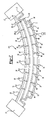
- Figure 1 illustrates a vehicle suspension system including leaf springs and the structure of the present invention;
- Figure 2 illustrates a side view of the intermediate sheet, upper sheet, and lower sheet of the present invention stamped to a desired shape;
- Figure 3 illustrates a side view of the intermediate sheet, upper sheet, and lower sheet of the present invention including a plurality of elastic strips on the upper surfaces of the sheets;
- Figure 4 illustrates a side view of the intermediate sheet, upper sheet, and lower sheet of the present invention including a plurality of elastic strips on the lower surfaces of the sheets;
- Figure 5 illustrates a side view of the assembled structure of the present invention;
- Figure 6 illustrates a side view of a second embodiment of the present invention which utilizes rivets;
- Figure 7 illustrates the present invention utilizing electrical elements; and
- Figure 8 illustrates a perspective view of the embodiment illustrated in Figure 7;
- Figure 9 illustrates the present invention utilizing piezo-elements; and
- Figure 10 illustrates a perspective view of the embodiment illustrated in Figure 9.
- Figure 1 illustrates a
vehicle suspension system 13. Thestructure 10 of the present invention is positioned between a suspension component, such as aleaf spring 11, providing damping forces and vibration attenuation between twovehicle frame members 15, shown schematically. Thestructure 10 may also be used in place of a standard sheet component, such as in a strut tower, in seats, and in a vehicle a sub-frame. - As illustrated in Figure 2, the
structure 10 is formed of anintermediate sheet 12, anupper sheet 18, and alower sheet 20. It is preferred that thesheets intermediate sheet 12 is perforated with a plurality ofholes 14 at defined sites and of a defined distribution, and thesheet 12 is stamped to a desired shape. Excess material is removed from theintermediate sheet 12 to create anintermediate edge 16. Although thestructure 10 can include any number ofintermediate sheets 12, only oneintermediate sheet 12 is described and illustrated. - The
upper sheet 18 andlower sheet 20 are stamped to a desired shape,sheets intermediate sheet 12 will substantially fit between theupper sheet 18 andlower sheet 20 when assembled to create thestructure 10. Excess material is removed from theupper sheet 18 andlower sheet 20, creating anupper edge 22 andlower edge 24, respectively, which are finished to form anupper flange 26 and alower flange 28, respectively. - As shown in Figure 3, a plurality of
elastic strips 30, preferably rubber, are bonded to thesheets elastic strips 30 are positioned between each of thesheets structure 10. Theelastic strips 30 are positioned to substantially extend across thesheets respective edges elastic strips 30 are bonded to theupper surface 32 of theintermediate sheet 12 and theupper surface 34 of thelower sheet 20, theupper sheet 18 including noelastic strips 30. In another embodiment, shown in Figure 4, the plurality ofelastic strips 30 are bonded to thelower surface 36 of theupper sheet 18 and thelower surface 38 of theintermediate sheet 12, thelower sheet 20 including noelastic strips 30. Theelastic strips 30 can also be bonded in other arrangements, such as only on theintermediate sheet 12 or alternatively only on theupper sheet 18 andlower sheet 20. - For certain stamping technologies, such as hydroforming, it is preferred to bond the
elastic strips 30 to thesheets elastic strips 30 are bonded to thesheets sheets elastic strips 30. - As further shown in Figures 3 and 4, a viscous fluid F is dispersed on the
upper surface 32 of theintermediate sheet 12 and theupper surface 34 of thelower sheet 20 by afluid dispenser 17 during assembly. - When assembled, fluid F is dispersed on the
upper surface 34 of thelower sheet 20, and theintermediate sheet 12 is positioned substantially over thelower sheet 20. Additional fluid F is then dispersed on theupper surface 32 of theintermediate sheet 12, theupper sheet 18 being positioned substantially over theintermediate sheet 12. - As illustrated in Figure 5, when assembled, the
upper flange 26 of theupper sheet 18 substantially contacts thelower flange 28 of thelower sheet 18. The contactinglower flange 28 andupper flange 26 are secured, sealing the viscous fluid F within thestructure 10. It is preferred that theflanges structure 10 be secured by welding, such as seam-welding. Thewelding 40 extends substantially around the entireupper edge 22 andlower edge 24 of thestructure 10, theintermediate edge 16 of theintermediate sheet 12 being trapped within thestructure 10. The assembledstructure 10 provides vibration attenuation and damping when it is compressed, extended, bent or submitted to vibrations as the fluid F passes through the plurality ofholes 14. - Figure 6 illustrates an alternative embodiment of the present invention. In this embodiment, the
intermediate sheet 12 is substantially smaller in dimension than theupper sheet 18 and thelower sheet 20. When thestructure 10 is assembled, a continuouselastic sealing strip 42 is positioned substantially inside theedges upper sheet 20 andlower sheet 22, respectively, but outside of theintermediate edge 16 of theintermediate sheet 12. The sealingstrip 42 contains the fluid F in thestructure 110. Theupper sheet 18 andlower sheet 20 are secured together by a plurality ofattachment members 48 positioned substantially outside of the sealingstrip 42. Thesheets holes 46. When thestructure 110 is assembled, theholes 46 in theupper sheet 18 substantially align withholes 46 in thelower sheet 20 to receive theattachment members 48, such as rivets. Theattachment member 48 maintains compression force and presses on the sealingstrip 42 to contain the fluid F within thestructure 110. - Further damping can occur by using electro-rheological or magnetic-rheological fluid F, as illustrated in the
vehicle suspension system 113 shown in Figure 7. When in the liquid state, the electro-rheological or magnetic-rheological fluid F is flexible and soft.Electrical elements 58, such as capacitors or coils, are located on aload carrying member 60 and connected by a plurality oflead wires 62, shown in Figure 8. A control voltage generated by apower source 64 is applied to theelectrical elements 58 to generate an electric field or a magnetic field, supplying voltage to thestructure 10 by a connectingwire 66. Thepower source 64 is either inside the system or outside the system, such as a battery. The control voltage increase the viscosity of the fluid F, increasing the relative stiffness of thestructure 10. - Alternatively, as shown in Figure 9, a
vehicle suspension system 13 usesenergy converters 52 to transfer the mechanical energy into electrical energy to control the viscosity of the electro-rheological or magnetic-rheological fluid F. When in the liquid state, the electro-rheological or magnetic-rheological fluid F is flexible and soft. Theconverters 52 can be a plurality of piezo-elements 52 mounted to acharge strip 50 on aload carrying member 11, such as a leaf spring, to derive the electrical input which increases the viscosity of the fluid F and the stiffness of thestructure 10. The piezo-elements 52 are connected by a plurality oflead wires 54. Preferably, the piezo-elements 52 be bonded or glued to thecharge strip 50. An increase in load deflects and energizes the piezo-elements 52 to produce an electrical input, supplying voltage to thestructure 10 by a connectingwire 54, as illustrated in Figure 10. The electrical input increases the viscosity of the fluid F, increasing the relative stiffness of thestructure 10 and producing damping by the opposing forces created in thestructure 10. The voltage signal is related to the displacement of the suspension and the piezo-element 52 deflection and provides voltage at desired locations of thestructure 10. The piezo-elements 52 can provide constant voltage to selected portions of thestructure 10, allowing for control over the feel of the ride. - There are several advantages to utilizing the
structure 10 of the present invention in a vehicle. For one, thestructure 10 provides damping and vibration attenuation, reducing vibration and noise. Additionally, there is more freedom in designing components for a vehicle. - The foregoing description is only exemplary of the principles of the invention. Many modifications and variations of the present invention are possible in light of the above teachings. The preferred embodiments of this invention have been disclosed, however, so that one of ordinary skill in the art would recognize that certain modifications would come within the scope of this invention. It is, therefore, to be understood that within the scope of the appended claims, the invention may be practiced otherwise than as specially described. For that reason the following claims should be studied to determine the true scope and content of this invention.
Claims (30)
- A method for forming a suspension structure comprising the steps of:forming a damping structure by forming a plurality of holes in at least one intermediate sheet, positioning said at least one intermediate sheet substantially between an upper sheet having an upper edge and a lower sheet having a lower edge, positioning a plurality of elastic members substantially between each of said sheets, dispensing a fluid substantially between each of said sheets, securing said upper sheet and said lower sheet substantially proximate to said upper edge and said lower edge to contain said fluid; andattaching said damping structure into a suspension component.
- The method as recited in claim 1 further comprising the step of shaping said upper sheet, said lower sheet, and said at least one intermediate sheet to a desired shape, each of said sheets being substantially shaped such that said sheets substantially interfit when assembled.
- The method as recited in claim 1 or 2 wherein the step of positioning said plurality of elastic members further comprises securing each of said plurality of elastic members to an upper surface of each of said at least one intermediate sheet and to an upper surface of said lower sheet.
- The method as recited in claim 1 or 2 wherein the step of positioning said plurality of elastic members further comprises securing each of said plurality of elastic members to a lower surface of each of said at least one intermediate sheet and to a lower surface of said upper sheet.
- The method as recited in any preceding claim wherein the step of securing said upper sheet to said lower sheet further includes welding said upper edge of said upper sheet to said lower edge of said lower sheet.
- The method as recited in any one of claims 1 to 4 wherein the step of securing said upper sheet to said lower sheet further includes passing a plurality of attachments members through a plurality of aligned holes on said upper sheet and said lower sheet, said fluid being contained by a continuous elastic strip positioned substantially between said upper sheet and said lower sheet.
- The method as recited in claim 6 wherein said plurality of attachment members are positioned substantially between said elastic strip and said aligned upper edge and said lower edge.
- The method as recited in claim 6 or 7 wherein said plurality of attachment members are rivets.
- The method as recited in any preceding claim further comprising the step of securing and electrically connecting a plurality of piezo-elements to a spring, said piezo-elements being electrically connected to said structure, said fluid being reactive to an electrical input produced by said plurality of piezo-elements by a load applied to said spring.
- The method as recited in claim 9 wherein said piezo-elements apply said electric input to said fluid to substantially alter a state of said fluid.
- The method as recited in claim 9 or 10 wherein said fluid is electro-rheological.
- The method as recited in claim 9 or 10 wherein said fluid is magnetic-rheological.
- The method as recited in any one of claims 1 to 8 further comprising the steps of securing a plurality of electrical elements to a load carrying member, said electrical elements being electrically connected to said structure, and applying a voltage to said electrical elements to produce an electrical input to substantially alter a state of said fluid.
- The method as recited in any preceding claim wherein a flow of said fluid through said plurality of holes provides a damping effect.
- A vehicle suspension system comprising:at least one suspension component; andat least one damping structure connected to said suspension component, each of said plurality of damping structures including at least one intermediate sheet having a plurality of holes, said at least one intermediate sheet being positioned substantially between an upper sheet having an upper edge and a lower sheet having a lower edge, each of said plurality of damping structures further including a plurality of elastic members positioned substantially between each of said sheets, said upper sheet and said lower sheet being secured substantially proximate to said upper edge and said lower edge to contain a fluid within each of said damping structures.
- The vehicle suspension system as recited in claim 15 wherein there are a plurality of suspension components and a plurality of damping structures, each of said plurality damping structures being positioned substantially between said plurality of suspension components.
- The vehicle suspension system as recited in claim 15 or 16 wherein said suspension component is a spring.
- The vehicle suspension system as recited in any one of claims 15 to 17 wherein said upper sheet, said lower sheet, and said at least one intermediate sheet are made of steel.
- The vehicle suspension system as recited in any one of claims 15 to 18 wherein there are one of said at least one intermediate sheet.
- The vehicle suspension system as recited in any one of claims 15 to 19 wherein said at least one elastic member is made of rubber.
- The vehicle suspension system as recited in any one of claims 15 to 20 wherein said plurality of elastic members are positioned on an upper surface of each of said at least one intermediate sheet and to an upper surface of said lower sheet.
- The vehicle suspension system as recited in any one of claims 15 to 20 wherein said plurality of elastic members are positioned on a lower surface of each of said at least one intermediate sheet and to a lower surface of said upper sheet.
- The vehicle suspension system as recited in any one of claims 15 to 22 wherein said upper sheet and said lower sheet are secured by welding.
- The vehicle suspension system as recited in any one of claims 15 to 22 wherein said upper sheet and said lower sheet are secured by attachment members.
- The vehicle suspension system as recited in any one of claims 15 to 24 wherein said vehicle suspension system further includes a plurality of piezo-elements electrically connected to said damping structure, said plurality of piezo-elements providing an electrical input to said damping structure under a load applied to said vehicle suspension system.
- The vehicle suspension system as recited in claim 25 wherein said electrical input substantially change a state of said fluid.
- The vehicle suspension system as recited in claim 25 or 26 wherein said fluid is electro-rheological.
- The vehicle suspension system as recited in claim 25 or 26 wherein said fluid is magnetic-rheological.
- The vehicle suspension system as recited in any one of claims 15 to 24 wherein said vehicle suspension system further includes a load carrying member including a plurality of electrical elements, said plurality of electrical elements being electrically connected to said structure to provide an electrical input to said structure when a voltage is applied to said electrical elements to produce said electrical input to substantially changes a state of said fluid.
- A vehicle suspension system comprising:a plurality of springs; anda plurality of damping structures, each of said plurality of said damping structures being positioned substantially between each of said plurality of springs, each of said plurality of damping structures including at least one intermediate sheet having a plurality of holes, said at least one intermediate sheet being positioned substantially between an upper sheet having an upper edge and a lower sheet having a lower edge, each of said plurality of damping structures further including a plurality of elastic members positioned substantially between each of said sheets, said upper sheet and said lower sheet being secured substantially proximate to said upper edge and said lower edge to contain a fluid within each of said damping structures.
Priority Applications (2)
| Application Number | Priority Date | Filing Date | Title |
|---|---|---|---|
| DE2003609283 DE60309283T2 (en) | 2003-03-17 | 2003-03-17 | damping structure |
| EP20030251617 EP1459916B1 (en) | 2003-03-17 | 2003-03-17 | Damping structure |
Applications Claiming Priority (1)
| Application Number | Priority Date | Filing Date | Title |
|---|---|---|---|
| EP20030251617 EP1459916B1 (en) | 2003-03-17 | 2003-03-17 | Damping structure |
Publications (2)
| Publication Number | Publication Date |
|---|---|
| EP1459916A1 true EP1459916A1 (en) | 2004-09-22 |
| EP1459916B1 EP1459916B1 (en) | 2006-10-25 |
Family
ID=32799053
Family Applications (1)
| Application Number | Title | Priority Date | Filing Date |
|---|---|---|---|
| EP20030251617 Expired - Lifetime EP1459916B1 (en) | 2003-03-17 | 2003-03-17 | Damping structure |
Country Status (2)
| Country | Link |
|---|---|
| EP (1) | EP1459916B1 (en) |
| DE (1) | DE60309283T2 (en) |
Cited By (1)
| Publication number | Priority date | Publication date | Assignee | Title |
|---|---|---|---|---|
| DE102020127866A1 (en) | 2020-10-22 | 2022-04-28 | Rheinmetall Invent GmbH | spring device |
Families Citing this family (2)
| Publication number | Priority date | Publication date | Assignee | Title |
|---|---|---|---|---|
| DE102010038222A1 (en) * | 2010-10-15 | 2012-04-19 | Dr. Ing. H.C. F. Porsche Aktiengesellschaft | Damper device, particularly guide support for vehicle suspension strut, particularly motor vehicle shock absorber, has base body, where hollow chamber, filled with magneto-rheological substance, is provided inside base body |
| DE102010043333B4 (en) * | 2010-11-03 | 2014-10-23 | Deutsches Zentrum für Luft- und Raumfahrt e.V. | Flexible element |
Citations (7)
| Publication number | Priority date | Publication date | Assignee | Title |
|---|---|---|---|---|
| US1707111A (en) * | 1928-02-10 | 1929-03-26 | Brady Delfred Francisco | Hydraulic shock absorrer |
| JPS612932A (en) * | 1984-06-13 | 1986-01-08 | Horikiri Bane Seisakusho:Kk | hollow leaf spring device |
| DE4021166A1 (en) * | 1989-07-29 | 1991-02-07 | Volkswagen Ag | Wheel suspension with lower link arm - has wheel supported by two-leaf leaf spring with pneumatic and/or hydraulic expansion device fitted between the leaves |
| US5068018A (en) * | 1990-01-10 | 1991-11-26 | Lord Corporation | Electrophoretic fluid composite structure |
| DE4337200A1 (en) * | 1993-10-30 | 1995-05-04 | Vorwerk Co Interholding | Component |
| DE19743543A1 (en) * | 1997-10-01 | 1999-04-08 | Peter Dipl Ing Denk | Shock absorber for motor vehicles |
| FR2828253A1 (en) * | 2001-08-02 | 2003-02-07 | Woco Franz Josef Wolf & Co Gmbh | Pneumatic bearing for motor vehicle has pneumatic and damping rings between metal supporting plate and frame |
-
2003
- 2003-03-17 DE DE2003609283 patent/DE60309283T2/en not_active Expired - Fee Related
- 2003-03-17 EP EP20030251617 patent/EP1459916B1/en not_active Expired - Lifetime
Patent Citations (7)
| Publication number | Priority date | Publication date | Assignee | Title |
|---|---|---|---|---|
| US1707111A (en) * | 1928-02-10 | 1929-03-26 | Brady Delfred Francisco | Hydraulic shock absorrer |
| JPS612932A (en) * | 1984-06-13 | 1986-01-08 | Horikiri Bane Seisakusho:Kk | hollow leaf spring device |
| DE4021166A1 (en) * | 1989-07-29 | 1991-02-07 | Volkswagen Ag | Wheel suspension with lower link arm - has wheel supported by two-leaf leaf spring with pneumatic and/or hydraulic expansion device fitted between the leaves |
| US5068018A (en) * | 1990-01-10 | 1991-11-26 | Lord Corporation | Electrophoretic fluid composite structure |
| DE4337200A1 (en) * | 1993-10-30 | 1995-05-04 | Vorwerk Co Interholding | Component |
| DE19743543A1 (en) * | 1997-10-01 | 1999-04-08 | Peter Dipl Ing Denk | Shock absorber for motor vehicles |
| FR2828253A1 (en) * | 2001-08-02 | 2003-02-07 | Woco Franz Josef Wolf & Co Gmbh | Pneumatic bearing for motor vehicle has pneumatic and damping rings between metal supporting plate and frame |
Non-Patent Citations (1)
| Title |
|---|
| PATENT ABSTRACTS OF JAPAN vol. 010, no. 146 (M - 482) 28 May 1986 (1986-05-28) * |
Cited By (1)
| Publication number | Priority date | Publication date | Assignee | Title |
|---|---|---|---|---|
| DE102020127866A1 (en) | 2020-10-22 | 2022-04-28 | Rheinmetall Invent GmbH | spring device |
Also Published As
| Publication number | Publication date |
|---|---|
| EP1459916B1 (en) | 2006-10-25 |
| DE60309283T2 (en) | 2007-04-05 |
| DE60309283D1 (en) | 2006-12-07 |
Similar Documents
| Publication | Publication Date | Title |
|---|---|---|
| EP3048017A1 (en) | Damping force generation device for vehicle | |
| US8308148B2 (en) | Plug-in body mount damping device for vehicles | |
| US7270335B2 (en) | Electromagnetic suspension apparatus for automotive vehicles and method for controlling electric motor of the same | |
| JP3538364B2 (en) | shock absorber | |
| CA1301787C (en) | Fluid filled elastomeric damping device | |
| US7918438B2 (en) | Vibration isolator, and method of mounting the same | |
| US6641121B1 (en) | Damping structure | |
| JP2597393B2 (en) | Sleeve type rubber shock absorber | |
| JP2000046090A (en) | Spring seat fixing structure of hydraulic shock absorber | |
| EP1459916B1 (en) | Damping structure | |
| US6655669B1 (en) | Hydraulic strut mounting assembly | |
| KR101257544B1 (en) | Vibration Isolation System with Low Natural Frequency | |
| US4767134A (en) | Vehicle suspension system with multiple overlapping composite control arm elements | |
| US6722677B2 (en) | Connecting component | |
| NL2026911B1 (en) | Fuel Cells Mounting Concept | |
| EP1459817A1 (en) | Vehicle suspension system and method for forming connecting component used therein | |
| JP6541656B2 (en) | Damping fluid device, system and method | |
| JP2000337417A (en) | Air spring | |
| CA2030730C (en) | Fluid-damped strut | |
| EP2935931B1 (en) | Self-adjusting, self-damping air spring system and method of damping oscillation | |
| JPH04113044A (en) | Leaf spring device in one body with damper | |
| CN218929183U (en) | Bushing assembly, bushing suspension and vehicle | |
| JP2009085300A (en) | Upper support | |
| JPH02120106A (en) | Suspention device for vehicle | |
| JPH073072Y2 (en) | Vehicle strut device |
Legal Events
| Date | Code | Title | Description |
|---|---|---|---|
| PUAI | Public reference made under article 153(3) epc to a published international application that has entered the european phase |
Free format text: ORIGINAL CODE: 0009012 |
|
| AK | Designated contracting states |
Kind code of ref document: A1 Designated state(s): AT BE BG CH CY CZ DE DK EE ES FI FR GB GR HU IE IT LI LU MC NL PT RO SE SI SK TR |
|
| AX | Request for extension of the european patent |
Extension state: AL LT LV MK |
|
| 17P | Request for examination filed |
Effective date: 20040927 |
|
| 17Q | First examination report despatched |
Effective date: 20050119 |
|
| AKX | Designation fees paid |
Designated state(s): DE ES FR |
|
| GRAP | Despatch of communication of intention to grant a patent |
Free format text: ORIGINAL CODE: EPIDOSNIGR1 |
|
| RAP1 | Party data changed (applicant data changed or rights of an application transferred) |
Owner name: ARVINMERITOR TECHNOLOGY, LLC |
|
| GRAS | Grant fee paid |
Free format text: ORIGINAL CODE: EPIDOSNIGR3 |
|
| GRAA | (expected) grant |
Free format text: ORIGINAL CODE: 0009210 |
|
| AK | Designated contracting states |
Kind code of ref document: B1 Designated state(s): DE ES FR |
|
| REF | Corresponds to: |
Ref document number: 60309283 Country of ref document: DE Date of ref document: 20061207 Kind code of ref document: P |
|
| PG25 | Lapsed in a contracting state [announced via postgrant information from national office to epo] |
Ref country code: ES Free format text: LAPSE BECAUSE OF FAILURE TO SUBMIT A TRANSLATION OF THE DESCRIPTION OR TO PAY THE FEE WITHIN THE PRESCRIBED TIME-LIMIT Effective date: 20070205 |
|
| ET | Fr: translation filed | ||
| PLBE | No opposition filed within time limit |
Free format text: ORIGINAL CODE: 0009261 |
|
| STAA | Information on the status of an ep patent application or granted ep patent |
Free format text: STATUS: NO OPPOSITION FILED WITHIN TIME LIMIT |
|
| 26N | No opposition filed |
Effective date: 20070726 |
|
| REG | Reference to a national code |
Ref country code: FR Ref legal event code: ST Effective date: 20071130 |
|
| PG25 | Lapsed in a contracting state [announced via postgrant information from national office to epo] |
Ref country code: DE Free format text: LAPSE BECAUSE OF NON-PAYMENT OF DUE FEES Effective date: 20071002 |
|
| PG25 | Lapsed in a contracting state [announced via postgrant information from national office to epo] |
Ref country code: FR Free format text: LAPSE BECAUSE OF NON-PAYMENT OF DUE FEES Effective date: 20070402 |