EP1459592B1 - Signalpermutation - Google Patents
Signalpermutation Download PDFInfo
- Publication number
- EP1459592B1 EP1459592B1 EP02794403A EP02794403A EP1459592B1 EP 1459592 B1 EP1459592 B1 EP 1459592B1 EP 02794403 A EP02794403 A EP 02794403A EP 02794403 A EP02794403 A EP 02794403A EP 1459592 B1 EP1459592 B1 EP 1459592B1
- Authority
- EP
- European Patent Office
- Prior art keywords
- signals
- switches
- layer
- ordering
- msap
- Prior art date
- Legal status (The legal status is an assumption and is not a legal conclusion. Google has not performed a legal analysis and makes no representation as to the accuracy of the status listed.)
- Expired - Lifetime
Links
- 238000000034 method Methods 0.000 claims abstract description 7
- 238000010586 diagram Methods 0.000 description 7
- 238000013507 mapping Methods 0.000 description 4
- 238000005516 engineering process Methods 0.000 description 3
- 230000007704 transition Effects 0.000 description 3
- 239000004744 fabric Substances 0.000 description 2
- 230000000903 blocking effect Effects 0.000 description 1
- 238000010276 construction Methods 0.000 description 1
- 230000000644 propagated effect Effects 0.000 description 1
Images


Classifications
-
- H—ELECTRICITY
- H04—ELECTRIC COMMUNICATION TECHNIQUE
- H04Q—SELECTING
- H04Q3/00—Selecting arrangements
- H04Q3/64—Distributing or queueing
- H04Q3/68—Grouping or interlacing selector groups or stages
Definitions
- This invention relates to signal permuting.
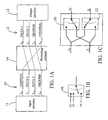
- Signal permuting is used to change the routing paths of signals to connect two interfaces whose sets of signal lines have different orderings. For example, as shown in Figure 1A , if an interface 10 to input circuitry 11 has lines L 0 to L 3 that carry Control, Data 1, Data 2, and Ground signals, and a second interface 12 to output circuitry 13 has lines Lo to L3 that carry Datal, Data 2, Ground, and Control signals, the input and output interfaces are coupled by a 4-by-4 permuting network 14 that maps [L 0 , L 1 , L 2 , L 3 ] to [L 3 , L 0 , L 1 , L 2 ].
- a permuting network can be implemented using switches.
- the output of an n :1 switch 16 can reflect any one of its n inputs.
- n signals can be permuted to any order at their output terminals.
- Fig. 1C shows a 2-by-2 permuting network implemented using two 2:1 switches 20, 22 that permutes the ordering of two signals S 0 and S 1 .
- An n :1 switch can be implemented using an n :1 multiplexer, a 2 n x1 random access memory that has its contents written to reflect a single address input, or an n- input lookup-table in a field programmable gate array that is programmed to reflect any one of its inputs at its output. For each type of technology, the types of switches that can be most economically implemented may be different.
- WO 98/20700 Al discloses a switching fabric wherein one-dimensional coordinates are assigned to input and output ports of switches.
- Fig. 1 shows input ports I1 to In, and output ports O1 to Om.
- the input and output ports thereof can be connected to different devices, and the switch fabric enables any device connected to any input port to send packets to any device connected to any output port.
- the invention is directed towards construction of a permuting network using a predetermined set of building blocks.
- the building blocks are programmable switches of one or more type, each type being able to select one signal from among several signals.
- the permuting network is configured as a multidimensional switch array permuter (MSAP) that can permute the ordering of signals by programming the switches to select signals according to a permuting algorithm.
- MSAP multidimensional switch array permuter
- each permuter has input terminals at its left and output terminals at its right.
- the numbers w 1 , w 2 , ..., w D are integers.
- Each layer contains the same number ( N ) of switches of the same type, but the types of switches may differ among different layers.
- layer L ⁇ includes w ⁇ :1 switches, each of which can select one signal from among w ⁇ signals.
- layer L 1 contains w 1 : 1 switches
- layer L 2 contains w 2 :1 switches
- layer L D contains w D :1 switches.
- ⁇ D +1 to 2 D -1
- layer L ⁇ contains (2 D - ⁇ ): switches.
- layer L D +1 contains w D -1 : 1 switches
- layer L 2 D +1 contains w 1 :1 switches.
- the input signals of the switches in layer L 1 are the N input signals of the MSAP.
- the w 1 :1 switches in the layer L 1 are configured to form a number of w 1 -by- w 1 permuters 202, the number being N / w 1 .
- Each w 1 -by- w 1 permuter 202 includes a number of w 1 :1 switches, the number being w 1 .
- Each w 1 -by- w 1 permuter 202 receives w 1 signals from the input terminals 204, and outputs a set of re-ordered w 1 signals on the output terminals 206.
- the output signals 206 of permuters 202 are sent to the input terminals of permuters in layer L 2 .
- the w 2 :1 switches in layer L 2 are configured to form a number of w 2 -by- w 2 permuters 208, the number being N / w 2 .
- Each w 2 -by- w 2 permuter 208 receives w 2 signals at its input terminals 210, and outputs a set of re-ordered w 2 signals at its output terminals 212.
- the output signals of permuters 208 are sent to the input terminals of permuters in layer L 3 , and so forth.
- the switch outputs in the last layer, L 2 D -1 are the outputs of the MSAP, which is a set of re-ordered N signals.
- the connections between the output terminals of one layer and the input terminals of the next layer are fixed (e.g., hardwired).
- the connections are represented by the regions 214 enclosed in dashed lines.
- the connections between each layer are configured so that each of the output signals of a permuter is sent to a different permuter in the next layer.
- each w ⁇ -by- w ⁇ permuter receives w ⁇ input signals from w ⁇ different pennuters in the previous layer, permutes the order of the w ⁇ signals, and sends the re-ordered w ⁇ signals to w ⁇ different permuters in the next layer.
- An advantage of the invention is that the MSAP can be designed and constructed using various types of switches, depending on which types are available.
- the factors w i of N are first determined.
- the basic building block may be 2:1 switches, and all other n :1 switches are constructed from the 2:1 switches.
- the basic building blocks may include both 2:1 and 3:1 switches, and larger switches are built from these two types of switches.
- An N -by- N MSAP may be constructed using building blocks that are the most economical for that particular environment.
- n 2 and use 2:1 switches as the basic building blocks of the MSAP. See Table 1 below for a comparison of the efficiency of MSAP's constructed using switches of various sizes.
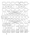
- a 12-by-12 MSAP 300 is constructed from two layers of 3:1 switches and one layer of 4:1 switches.
- MSAP 300 includes layers L 1 to L 3 .
- Layer L 1 includes 3:1 switches that are configured to form 3-by-3 permuters 302, 304, 306, and 308.
- Layer L 2 includes 4:1 switches that are configured to form 4-by-4 permuters 310, 312, and 314.
- Layer L 3 includes 3:1 switches that are configured to form 3-by-3 permuters 316, 318, 320, and 322.
- Each 3-by-3 permuter in layer L 1 receives 3 signals at its input terminals, permutes the ordering of the 3 signals, and sends the re-ordered 3 signals to three different permuters in layer L 2 .
- the first output terminal of permuter 302 is connected to the first input terminal of permuter 310.
- the second output of permuter 302 is connected to the first input of permuter 312.
- the third output of permuter 302 is connected to the first input of permuter 314, and so forth. In this way, each of the three output signals of a permuter in the layer L 1 will be re-ordered by a different permuter in the layer L 2 .
- each output of a permuter in the layer L 2 is connected to an input of a different permuter in layer L 3 .
- each of the four output signals of a permuter in layer L 2 will be re-ordered by a different permuter in layer L 3 .
- the 12-by-12 MSAP can re-order 12 input signals into any orderings of the 12 output signals.
- each permuter represents routing of signals from input terminals to output terminals.
- Twelve input signals with the ordering [S 1 , S 2 , ..., S 12 ] are re-ordered into ordering [S 7 , S 5 , S 3 , S 9 , S 8 , S 1 , S 10 ), S 2 , S 6 , S 12 , S 11 , S 4 ] at the output of MSAP 300.
- the following illustrates how signal S 3 is re-ordered from line #3 at the input terminal at the left of the figure to line #6 at the output terminal at the right of the figure.
- Permuter 302 re-orders signal S 3 from input #3 to output #1, which is connected to input #1 of permuter 310.
- Permuter 310 re-orders signal S 3 from input # to output #2, which is connected to input #4 of permuter 318.
- Permuter 318 then re-orders signal S 3 from input #4 to output #6.
- the inputs and outputs of the permuters in each layer are numbered #1 to #12 from top to bottom in the figure.
- the following describes the connections between the output terminals of switches in one layer and the input terminals of switches in the next layer. These connections are fixed (e.g., hardwired).
- the switches in each layer of the MSAP are said to form a D-dimensional array.
- the switches in layer L ⁇ are denoted as S [ ⁇ ][ x 1 , x 2 , ..., x D ], with 1 ⁇ x k ⁇ Wk , k ranging from 1 to D .
- the number x 1 represents the 1 st dimension coordinate of the switch, the number x 2 represents the 2 nd dimension coordinate, and so forth.
- the inputs to these switches will be denoted by adding subscripts to the ends of switch names.
- switch S[1][2,3,4] has inputs S[1][2,3,4], S[1][2,3,4] 2 , etc.
- the outputs will be denoted by adding an asterisk (e.g. S[1][2,3,4]*).
- the output signals of the MSAP are the outputs of the last layer L 2 D -1 , i.e., the MSAP outputs are S[2 D -1][ x 1 , x 2 , ..., x D ]* for the various combinations of x 1 , x 2 , ..., x D .
- a fictional layer L 0 is used so that the MSAP inputs are the L 0 outputs.
- the MSAP inputs are S[0][ x 1 , x 2 , ..., x D ]* for the various combinations of x 1 , x 2 , ..., x D .
- S[0][1, ..., 1] there is a signal S[0][1, ..., 1]*, which is the MSAP input.
- the permuters in layer L ⁇ arbitrarily permute the outputs of the permuters in the previous layer along dimension ⁇ only. This means that the switches in a permuter in layer L ⁇ only receive signals from switches in the previous layer having labels that are different in dimension ⁇ , and only permute those signals.
- layer ⁇ arbitrarily permutes the outputs of the previous layer along dimension 2 D - ⁇ , only. This means that the switches in a permuter in layer L ⁇ only receive signals from switches in the previous layer having labels that are different in dimension 2 D - ⁇ , and only permute those signals.
- the switches in MSAP 300 have been labeled as S[ ⁇ ][ x 1 , x 2 ], ⁇ ranging from 1 to 3, x 1 ranging from 1 to 3, and x 2 ranging from 1 to 4.
- the MSAP input signals are described as the output signals of layer L 0 , and are labeled as S[0][ i,j ]*, i ranging from 1 to 3, and j ranging from 1 to 4.
- Layer L 1 permutes the signals along the first dimension. This means that the switches in layer L 0 , whose outputs are connected to the inputs of a switch in layer L 1 , have labels with different coordinates in the first dimension but same coordinates in the second dimension.
- Layer L 2 permutes the signals along the second dimension.
- the switches in L 1 whose outputs are connected to the inputs of a switch in L 2 , have labels with different coordinates in the second dimension but same coordinates in the first dimension.
- Layer L 3 permutes the signals along the first dimension.
- the output signals of MSAP 300 are the 12 switch outputs from layer L 3 , i.e., S[3][1,1]* through S[3][3,4]*.
- An MSAP switch topology has a recursive structure. If the first and last layers of switches (L 1 and L 2 D- 1 ) are removed from an MSAP of dimension D > 1, the remaining portion is a number of smaller MSAP's of dimension D -1, the number being w 1 .
- the subset of switches ⁇ S[ ⁇ ][c, x 2 , x 3 , ..., x D ] ⁇ ( ⁇ ranging from 2 to 2 D -2 and each x k ranging from 1 to w k ) forms a sub-MSAP of dimension D -1 with dimensional widths w 2 , w 3 , ..., w D .
- Each sub-MSAP has its own sub-MSAP's, and so forth, down to the level of one-dimensional MSAP's. This recursive structure of the MSAP is reflected in the MSAP switching algorithm described below.
- the switches in an MSAP are configured according to a switching algorithm so that the MSAP can permute signals in any chosen order.
- each input signal to the MSAP is described as having a starting position and a target position.
- the position of a signal in a particular layer is written as [ x 1 , x 2 , ..., x D ], and corresponds to the label of the switch that selected the signal as output.
- the signal at input line #3 has a starting position of [3,1] because the signal is selected by switch S[0][3,1] and reflected at its output.
- layer L 0 is a fictional layer and used just for convenience of description.
- This position path determines how one switch in each layer must be set. In order that the signal propagates from L 0 position [2,5,3] to L 1 position [8,5,3], switch S[1][8,5,3] must be set to position 2. In order that the signal propagates from L 1 position [8,5,3] to L 2 position [8,7,3], switch S[2][8,7,3] must be set to position 5, and so forth.
- all of the switches in the MSAP can be set so that all input signals are routed to the proper output terminals of the MSAP.
- a collection of N position paths can be used to determine a switch-setting configuration for an MSAP.
- the MSAP switching algorithm provides a way of configuring an MSAP to route input signals to achieve every possible signal permutation at the output terminals.
- the configuration provided by the switching algorithm is not the only way that an MSAP can be configured to permute signals. It is possible to use a "brute-force" method by looking through all possible switching combinations in some intelligent (e.g., recursive) manner to find a solution.
- the MSAP switching algorithm includes Algorithm 1, which calls Algorithm 2.
- Algorithm 1 determines the position paths for all the signals, giving each signal's position coordinates in each layer from L 0 to L 2 D -1 in a manner that is allowed by the MSAP topology. No two signals can occupy the same position in any layer.
- the L 0 position of each signal is its starting position.
- the L 2 D -1 position of each signal generated by Algorithm 1 will match the signal's target position.
- Step 3 Call Algorithm 2 to permute the L ⁇ positions of signals in ⁇ , changing only the ⁇ th position coordinate of each signal, in such a way that no two signals in ⁇ with the same ⁇ th position coordinate have identical ( ⁇ +1) st to D th target coordinates.
- Step 5 Permute the signals in ⁇ from their positions in L 2 D - ⁇ -1 to new positions in L 2 D - ⁇ , by changing the ⁇ th position coordinate of each signal to its ⁇ th target coordinate.
- the permutations performed in Steps 3 and 5 of Algorithm 1 permutes signals only along a particular dimension allowable for that layer. For example, the switches in layer L k permute signals only along dimension k .
- Algorithm 1 also follows the rule that no two signals occupy the same position in a given layer. This rule can be ensured because Algorithm 2, as described below, moves signals by swapping pairs of signals, thereby preventing collisions of signals (i.e., two signals being selected by the same switch).
- Algorithm 2 is a description of Algorithm 2 called by Step 3 of Algorithm 1. Due to the recursive nature of Algorithm 1, in layer L ⁇ , all the signals in ⁇ will have the same 1 st to ( ⁇ -1) st position coordinates. Their ⁇ th to D th position coordinates, on the other hand, will run through all possible combinations. Thus, although each signal still has D position coordinates, ⁇ is effectively a ( D - ⁇ +1)-dimensional array of signals according to positions in layer L ⁇ . The ⁇ th position coordinate of each signal in ⁇ determines the "slice" of this array that signal is in.
- the ( ⁇ +1) st to D th position coordinates of each signal determine the "column" of the array that the signal is in.
- the definitions of "slice” and “column” are given later.
- Two signals with the same ⁇ th position coordinates are in the same slice, and two signals with identical ( ⁇ +1) st to D th position coordinates are in the same column.
- the array of signals in ⁇ is divided into w ⁇ different slices, numbered 1 through w ⁇ .
- the array is also divided into w ⁇ +1 ⁇ w ⁇ +2 ⁇ ... ⁇ w D different columns, not numbered.
- Step 3 of Algorithm 1 only changes the ⁇ th position coordinate of each signal so that a signal only moves within its column.
- ⁇ is a subset of signals with constant L 2 position coordinates in dimensions 1 and 2.
- Step 2 of Algorithm 1 the L 2 positions of the signals in ⁇ are copied to their L 3 positions, so the L 3 positions of the 24 signals are also of the form [4,2,_,_,_].
- Algorithm 2 is called to rearrange the 24 signals in ⁇ within layer L 3 , i.e., Algorithm 2 changes the L 3 position coordinates of the 24 signals in ⁇ .
- Algorithm 2 divides the 24 signals in ⁇ into 4 "slices" and 6 "columns" based on their position coordinates. Each of the 4 slices have 6 signals, and each of the 6 columns have 4 signals.
- Slice k contains those signals in ⁇ whose 3 rd L 3 position coordinate is k.
- slice 3 contains 6 signals whose L 3 position coordinates are [4,2,3,1,1], [4,2,3,1,2], [4,2,3,2,1], [4,2,3,2,2], [4,2,3,3,1], and [4,2,3,3,2].
- the signals in slice 3 have these six L 3 positions, although the particular signals occupying those positions may change.
- Algorithm 2 works by "fixing" one slice at a time, i.e., once a slice is fixed, its signals are not changed in successive calls to the algorithm.
- the WHILE condition of step 2 checks the current slice for precisely the property that Algorithm 2 is trying to eliminate. When this property is no longer found, that slice is fixed. A fairly small number of times through Steps 3-13 always fixes a slice.
- Steps 3-13 The goal of Steps 3-13 is to move a signal with "duplicate" ( ⁇ +1) st to D th target coordinates out of layer S , replacing it with some other signal from above layer S whose ( ⁇ +1) st to D th target coordinates are missing from layer S .
- Algorithm 2 just swaps the two signals.
- such a pair of signals may not be in the same column, so a chain of swaps are performed, each of which operates within a different column.
- the first swap operation moves a signal with missing ( ⁇ +1) st to D th target coordinates into layer S
- the last swap operation moves a signal with duplicate ( ⁇ +1) st to D th target coordinates out of layer S.
- Fig. 4A shows an example of a mapping between the input and output terminals of MSAP 300.
- Fig. 4B shows an example of how the position coordinates of the input signals of a 12-by-12 MSAP are changed from their starting position coordinates to their target position coordinates.
- the changes in position coordinates were determined using Algorithm 1 and Algorithm 2 above.
- Layer L 1 only changes the coordinates of the first dimension
- layer L 2 only changes the coordinates of the second dimension
- layer L 3 only changes the coordinates of the first dimension.
- An advantage of an MSAP is that it efficiently uses pre-selected switches as basic building blocks.
- a computer 500 includes a daughter board 506 coupled to a motherboard 502 through an interface 504 that has signals lines #1 I to #12.
- the daughter board 506 includes a memory 512 that can be accessed by motherboard 502.
- Daughter board 506 and motherboard 502 are manufactured by different companies so that motherboard 502 sends signals on the signal lines of interface 504 in an order that is different from the order recognized by memory 512.
- Daughter board 506 includes a permuting network 508 that has input terminals connected to interface 504 and output terminals connected to an interface 510, which in turn is connected to memory 512.
- Permuting network 508 routes the signals in the signal lines of interface 504 to the signal lines of interface 510 with a new ordering that is acceptable to memory 512.
- the mapping between signal lines of interface 504 and signal lines of interface 510 is shown in Fig. 5B . As an example, the signal s1 on line #1 of interface 504 is mapped to line #7 of interface 510, and signal s12 on line #12 of interface 504 is mapped to line #4 of interface 510.
- the signals sent from memory 512 are re-ordered by permuting network 508 and then passed on to motherboard 502.
- Permuting network 508 is implemented using a field programmable logic array (FPGA).
- FPGA field programmable logic array
- the FPGA includes configurable logic components, each of which can be programmed to receive a number of inputs and to pass any one of the inputs to its outputs, just like an n: switch.
- daughter board 506 communicates with motherboard 502 to determine the required permutation.
- a processor (not shown) on daughter board 506 executes an MSAP switching algorithm to program the configurable logic components to construct an MSAP that achieves the required permutation.
- a 18-by-18 MSAP 600 is constructed from four layers of 3:1 switches and one layer of 2:1 switches.
- MSAP 600 includes layers L 1 to L 5 .
- Layers L 1 , L 2 , L 4 , and L 5 include 3:1 switches that are configured to form 3-by-3 permuters.
- Layer L 3 includes 2:1 switches that are configured to form 2-by-2 permuters. Within each permuter, different switches select different input signals so that there is no overlap in their selections. This results in a re-ordering of the input signals appearing at the output terminals of the permuter.
- the switch labels are shown inside the permuters.
- the three switches in a permuter 602 in layer L 1 have the same 2 nd and 3 rd coordinates but different 1 st coordinates.
- permuter 602 permutes the position coordinates of input signals in the first dimension.
- other permuters in layer L 1 also permute the position coordinates of input signals in the first dimension.
- the three switches in a permuter 604 in layer L 2 have the same 1 st and 3 rd coordinates but different 2 nd coordinates.
- permuter 604 permutes the position coordinates of input signals in the second dimension.
- other permuters in layer L 2 also permute the position coordinates of input signals in the second dimension.
- permuters in layer L 3 permute the position coordinates of input signals in the third dimension.
- Permuters in layer L 4 permute the position coordinates of input signals in the second dimension.
- Permuters in layer L 5 permute the position coordinates of input signals in the first dimension.
- MSAP 600 is designed to allow any of the 18 input signals to be routed to any of the 18 output terminals.
- the MSAP switching algorithm is performed to determine the transition paths for the 18 input signals.
- the transition paths go through the five layers of switches in a way such that each signal is routed to the desired output terminal and that no two signals occupy the same switch.
- the switches are then programmed to select input signals according to the signal paths determined by the MSAP switching algorithm.
- the switches may be implemented using devices other than an FPGA.
- the switches may be programmed by a processor on the motherboard rather than by a processor on the daughter board.
- the configuration of switches i.e., which signal is selected from its inputs and reflected at the output
- the configuration of switches may be dynamically programmable, or be programmable once and then fixed permanently.
- An MSAP that performs bit permutations can be used as a building block of an encoder/decoder that encrypts/decrypts messages.
- the MSAP can be used to construct telecommunication networks to route signals from nodes at one location to nodes at another location in a non-blocking manner.
- the MSAP can also be used in massively parallel or supercomputing applications to route signals among different processors.
Landscapes
- Engineering & Computer Science (AREA)
- Computer Networks & Wireless Communication (AREA)
- Design And Manufacture Of Integrated Circuits (AREA)
- Error Detection And Correction (AREA)
- Use Of Switch Circuits For Exchanges And Methods Of Control Of Multiplex Exchanges (AREA)
- Measuring Or Testing Involving Enzymes Or Micro-Organisms (AREA)
- Breeding Of Plants And Reproduction By Means Of Culturing (AREA)
- Credit Cards Or The Like (AREA)
- Control Of Motors That Do Not Use Commutators (AREA)
Claims (11)
- Verfahren, das Folgendes umfasst:Empfangen von N Signalen, die eine erste Reihenfolge aufweisen,;Aufbauen eines Permutationsnetzes (508) unter Verwendung von Schichten von Schaltern mit einer Konfiguration auf der Basis von ganzzahligen Faktoren von N und von einem oder mehreren zuvor ausgewählten Typen von Schaltern, wobei jede Schicht N Schalter desselben Typs aufweist,wobei die ganzzahligen Faktoren w1, w2, ..., wD (wobei D eine ganze Zahl ist) sind, dergestalt, dass N = w1 × w2 × ... × wD, und die zuvor ausgewählten Typen von Schaltern w1:1, w2:1, ..., und wD:1 Schalter enthalten, unddas Aufbauen das Zuweisen von mehrdimensionalen Koordinaten zu den Schaltern umfasst, wobei jeder Schalter eine Koordinate aufweist, die die gleiche ist wie ein anderer Schalter in der nächste Schicht; undUmordnen der N Signale unter Verwendung des Permutationsnetzes (508) dergestalt, dass die N Signale eine zweite Reihenfolge aufweisen.
- Verfahren nach Anspruch 1, wobei jeder Schaltertyp eine vorgegebene Anzahl von Eingangsanschlüssen und einen Ausgangsanschluss aufweist.
- Verfahren nach Anspruch 2, wobei jede Schicht des Permutationsnetzes (508) die N Signale zu Teilmengen von Signalen gruppiert und die Reihenfolge der Teilmengen von Signalen permutiert, wobei die Anzahl von Signalen in den Teilmengen gleich der Anzahl von Eingangsanschlüssen ist, die jeder Schalter in der Schicht hat.
- Verfahren nach Anspruch 2, wobei jeder Schalter in einer Schicht eine andere Koordinate hat, und wobei das Aufbauen des Permutationsnetzes (508) das Konfigurieren der Schalter in einer solchen Weise umfasst, dass, wenn sich ein Signal von einem ersten Schalter in einer Schicht zu einem zweiten Schalter in der nächsten Schicht ausbreitet, sich die Koordinaten der zwei Schalter maximal einer Dimension unterscheiden.
- Vorrichtung, die Folgendes umfasst:ein erstes Bauelement (502), das dafür vorkonfiguriert ist, N Signale zu erzeugen, die eine erste Reihenfolge ausweise, wobei N eine ganze Zahl ist, N = w1 × w2 × ... × wD, w1, w2, ..., wD ganzzahlige Faktoren von N sind, und mindestens zwei von w1, w2, ..., wD voneinander verschieden sind;ein zweites Bauelement (512), das dafür vorkonfiguriert ist, die N Signale zu empfangen, die in einer zweiten Reihenfolge angeordnet sind; undein Permutationsnetz (508), das dafür konfiguriert ist, die N Signale, die die erste Reihenfolge aufweisen, zu empfangen und die N Signale so umzuordnen, dass die N Signale die zweite Reihenfolge aufweisen, die durch das zweite Bauelement akzeptiert werden kann, wobei das Permutationsnetz aus Schichten von Schaltern aufgebaut ist, die w1:1, w2:1, ..., und wD:1 Schalter enthalten oder aus w1:1, w2:1, ..., und wD:1 Schaltern aufgebaut sind, wobei jede Schicht die gleiche Anzahl von Schaltern desselben Typs aufweist.
- Vorrichtung nach Anspruch 5, wobei die Anzahl von Schichten und die Verbindung zwischen Schaltern von aufeinanderfolgenden Schichten auf einem Satz ganzzahliger Faktoren von N und auf den Typen von verwendeten Schaltern basieren.
- Vorrichtung nach Anspruch 6, wobei das zweite Bauelement ein Speicher (512) ist.
- Vorrichtung nach Anspruch 7, wobei das erste Bauelement die Hauptplatine (502) eines Computers ist.
- Vorrichtung nach Anspruch 6, wobei die ganzzahligen Faktoren w1, w2, ..., wD (wobei D eine ganze Zahl ist) sind, dergestalt, dass N = w1 × w2 × ... × wD, und die Typen der verwendeten Schalter w1:1, w2:1, ..., und wD:1 Schalter enthalten.
- Vorrichtung nach Anspruch 9, wobei das Permutationsnetz dafür konfiguriert ist, 2D-1 Schichten von Schaltern zu haben, wobei jede Schicht N Schalter desselben Typs aufweist, wobei jede Schicht die Reihenfolge verschiedener Teilmengen der N Signale permutiert.
- Vorrichtung (508) zum Umordnen von N Signalen, die Folgendes umfasst:(2D-1) Schichten von Schaltern, wobei D eine ganze Zahl ist, wobei die n-te Schicht und die (2D - n)-te Schicht wn mal wn Schalter aufweisen, wobei n im Bereich von 1 bis D liegt, und w1 bis wD ganzzahlige Faktoren von N sind, dergestalt, dass N = w1 × w2 × ... × wD, und mindestens zwei von w1, w2, .., wD voneinander verschieden sind, wobei die erste Schicht von Schaltern die Reihenfolge von N Signalen umordnet, um einen ersten Satz umgeordneter Signale zu erzeugen, wobei die i-te Schicht von Schaltern den (i - 1)-ten Satz umgeordneter Signale umordnet, um einen i-ten Satz umgeordneter Signale zu erzeugen, wobei i im Bereich von 2 bis 2D - 1 liegt, wobei der (2D - 1)-te Satz umgeordneter Signale mit einer Zielreihenfolge von N Signalen übereinstimmt,wobei jedem der N Signale D-dimensionale Koordinaten zugeordnet sind, wobei die n-te Koordinate im Bereich von 1 bis wn liegt, wobei die Schalter der p-ten Schicht dafür konfiguriert sind, Signale zu tauschen, die sich nur in den p-ten Koordinaten unterscheiden, wobei die Koordinaten in anderen Dimensionen die gleichen sind, wobei p im Bereich von 1 bis D liegt, und die Schalter der q-ten Schicht dafür konfiguriert sind, Signale zu tauschen, die sich nur in den (2D - q)-ten Koordinaten unterscheiden, wobei die Koordinaten in anderen Dimensionen die gleichen sind, wobei q im Bereich von D+1 bis 2D-1 liegt.
Applications Claiming Priority (3)
| Application Number | Priority Date | Filing Date | Title |
|---|---|---|---|
| US34340 | 1993-03-19 | ||
| US10/034,340 US7177301B2 (en) | 2001-12-27 | 2001-12-27 | Signal permuting |
| PCT/US2002/041311 WO2003059004A1 (en) | 2001-12-27 | 2002-12-19 | Signal permuting |
Publications (2)
| Publication Number | Publication Date |
|---|---|
| EP1459592A1 EP1459592A1 (de) | 2004-09-22 |
| EP1459592B1 true EP1459592B1 (de) | 2010-10-27 |
Family
ID=21875812
Family Applications (1)
| Application Number | Title | Priority Date | Filing Date |
|---|---|---|---|
| EP02794403A Expired - Lifetime EP1459592B1 (de) | 2001-12-27 | 2002-12-19 | Signalpermutation |
Country Status (8)
| Country | Link |
|---|---|
| US (1) | US7177301B2 (de) |
| EP (1) | EP1459592B1 (de) |
| CN (1) | CN1608392B (de) |
| AT (1) | ATE486465T1 (de) |
| AU (1) | AU2002359839A1 (de) |
| DE (1) | DE60238137D1 (de) |
| TW (1) | TWI231121B (de) |
| WO (1) | WO2003059004A1 (de) |
Families Citing this family (4)
| Publication number | Priority date | Publication date | Assignee | Title |
|---|---|---|---|---|
| US20140133483A1 (en) * | 2012-11-14 | 2014-05-15 | Broadcom Corporation | Distributed Switch Architecture Using Permutation Switching |
| US9077338B1 (en) * | 2014-05-20 | 2015-07-07 | Altera Corporation | Method and circuit for scalable cross point switching using 3-D die stacking |
| CN104933008B (zh) * | 2015-06-24 | 2018-12-14 | 东南大学 | 可重构系统和可重构阵列结构及其应用 |
| CN114398301A (zh) * | 2021-12-10 | 2022-04-26 | 江苏清微智能科技有限公司 | 多通道访问存储部件以及处理器 |
Family Cites Families (14)
| Publication number | Priority date | Publication date | Assignee | Title |
|---|---|---|---|---|
| NL8104358A (nl) | 1981-09-22 | 1983-04-18 | Nederlanden Staat | Werkwijze en inrichting voor het besturen van een schakelnetwerk. |
| US4807280A (en) * | 1987-09-18 | 1989-02-21 | Pacific Bell | Cross-connect switch |
| US4833468A (en) * | 1987-10-14 | 1989-05-23 | Unisys Corporation | Layered network |
| US5430561A (en) * | 1991-07-17 | 1995-07-04 | Fujitsu Limited | Optical space switch employing 2 parallel diffraction gratings and a polarization rotating element |
| US5377182A (en) * | 1993-08-18 | 1994-12-27 | The United States Of America As Represented By The Administrator Of The National Aeronautics And Space Administration | Non-blocking crossbar permutation engine with constant routing latency |
| CN1240564A (zh) * | 1996-11-06 | 2000-01-05 | 诺基亚电信公司 | 交换结构 |
| FI103312B1 (fi) | 1996-11-06 | 1999-05-31 | Nokia Telecommunications Oy | Kytkentämatriisi |
| US6087958A (en) | 1997-07-14 | 2000-07-11 | Arzt; Lawrence J. | Multi-stage routing switchers with sequential and non-repetitive distributive circuit interconnections |
| US6215786B1 (en) * | 1998-04-06 | 2001-04-10 | Lockheed Martin Corporation | Implementation of multi-stage switching networks |
| WO2000024224A1 (en) | 1998-10-16 | 2000-04-27 | Laben S.P.A. | Architecture for managing transmission channels in telecommunication system switch, particularly for satellite applications |
| US6721311B1 (en) * | 1999-08-10 | 2004-04-13 | Colorado Seminary | Self-routing permutation networks based on de Bruijn digraphs |
| US6591285B1 (en) * | 2000-06-16 | 2003-07-08 | Shuo-Yen Robert Li | Running-sum adder networks determined by recursive construction of multi-stage networks |
| US6853635B1 (en) * | 2000-07-24 | 2005-02-08 | Nortel Networks Limited | Multi-dimensional lattice network |
| US6608575B2 (en) * | 2001-01-31 | 2003-08-19 | Qualcomm Incorporated | Hybrid multi-stage circuit |
-
2001
- 2001-12-27 US US10/034,340 patent/US7177301B2/en not_active Expired - Fee Related
-
2002
- 2002-12-19 AU AU2002359839A patent/AU2002359839A1/en not_active Abandoned
- 2002-12-19 AT AT02794403T patent/ATE486465T1/de not_active IP Right Cessation
- 2002-12-19 EP EP02794403A patent/EP1459592B1/de not_active Expired - Lifetime
- 2002-12-19 WO PCT/US2002/041311 patent/WO2003059004A1/en not_active Ceased
- 2002-12-19 CN CN02826091.0A patent/CN1608392B/zh not_active Expired - Fee Related
- 2002-12-19 DE DE60238137T patent/DE60238137D1/de not_active Expired - Lifetime
- 2002-12-26 TW TW091137489A patent/TWI231121B/zh not_active IP Right Cessation
Also Published As
| Publication number | Publication date |
|---|---|
| WO2003059004A1 (en) | 2003-07-17 |
| AU2002359839A1 (en) | 2003-07-24 |
| ATE486465T1 (de) | 2010-11-15 |
| US20030123439A1 (en) | 2003-07-03 |
| DE60238137D1 (de) | 2010-12-09 |
| TW200304293A (en) | 2003-09-16 |
| CN1608392A (zh) | 2005-04-20 |
| EP1459592A1 (de) | 2004-09-22 |
| US7177301B2 (en) | 2007-02-13 |
| CN1608392B (zh) | 2012-09-05 |
| TWI231121B (en) | 2005-04-11 |
Similar Documents
| Publication | Publication Date | Title |
|---|---|---|
| EP0397372B1 (de) | Netztopologie für reduzierte Blockierung und entsprechende photonische Systemausführung | |
| Voorhis | Memory systems for image processing | |
| US20020031124A1 (en) | Multistage interconnection networks of multicast concentrators with self-routing control mechanism | |
| US5023864A (en) | Crossover network utilizing two-dimensional arrays of nodes | |
| WO1991005375A1 (en) | Method and apparaus for simulating an interconnection network | |
| CA2048599C (en) | Optical interconnect networks | |
| EP0675665A2 (de) | Optische Zeitstufe und Betriebsverfahren | |
| US5319639A (en) | Crossbar with return net for scalable self-routing non-blocking message switching and routing system | |
| EP0397368B1 (de) | Steuerungsverfahren für Raumvielfachkoppelnetz | |
| US3916124A (en) | Nodal switching network arrangement and control | |
| US5036512A (en) | Optical apparatus for combining light beam arrays having different wavelengths | |
| US7177301B2 (en) | Signal permuting | |
| US7065076B1 (en) | Modular scalable switching networks | |
| US7388875B1 (en) | Fanout upgrade for a scalable switching network | |
| US6212179B1 (en) | Single-type fabric card networks and method of implementing same | |
| RU2249848C2 (ru) | Модуль для передачи и вещания сообщений в матричном коммутаторе | |
| Li et al. | ATM switching by divide-and-conquer interconnection of partial sorters | |
| GB2172174A (en) | Switching systems | |
| WO1992003792A1 (en) | Method and apparatus for routing and partitioning a multistage interconnection network and for determining network passability | |
| WO1993003580A1 (en) | Scalable self-routing nonblocking message switching and routing network | |
| Murdocca et al. | Design of Free Space Interconnected Signal Processor. | |
| Cypher et al. | Hypercube-Derived Computers | |
| WO1993003581A1 (en) | Message structure for scalable self-routing non-blocking message switching and routing system | |
| MXPA00003003A (es) | Metodos y aparatos para el procesamiento de una matriz de distribucion |
Legal Events
| Date | Code | Title | Description |
|---|---|---|---|
| PUAI | Public reference made under article 153(3) epc to a published international application that has entered the european phase |
Free format text: ORIGINAL CODE: 0009012 |
|
| 17P | Request for examination filed |
Effective date: 20040624 |
|
| AK | Designated contracting states |
Kind code of ref document: A1 Designated state(s): AT BE BG CH CY CZ DE DK EE ES FI FR GB GR IE IT LI LU MC NL PT SE SI SK TR |
|
| AX | Request for extension of the european patent |
Extension state: AL LT LV MK RO |
|
| 17Q | First examination report despatched |
Effective date: 20090807 |
|
| GRAP | Despatch of communication of intention to grant a patent |
Free format text: ORIGINAL CODE: EPIDOSNIGR1 |
|
| GRAS | Grant fee paid |
Free format text: ORIGINAL CODE: EPIDOSNIGR3 |
|
| GRAA | (expected) grant |
Free format text: ORIGINAL CODE: 0009210 |
|
| AK | Designated contracting states |
Kind code of ref document: B1 Designated state(s): AT BE BG CH CY CZ DE DK EE ES FI FR GB GR IE IT LI LU MC NL PT SE SI SK TR |
|
| REG | Reference to a national code |
Ref country code: GB Ref legal event code: FG4D |
|
| REG | Reference to a national code |
Ref country code: CH Ref legal event code: EP |
|
| REG | Reference to a national code |
Ref country code: IE Ref legal event code: FG4D |
|
| REF | Corresponds to: |
Ref document number: 60238137 Country of ref document: DE Date of ref document: 20101209 Kind code of ref document: P |
|
| REG | Reference to a national code |
Ref country code: NL Ref legal event code: VDEP Effective date: 20101027 |
|
| PG25 | Lapsed in a contracting state [announced via postgrant information from national office to epo] |
Ref country code: AT Free format text: LAPSE BECAUSE OF FAILURE TO SUBMIT A TRANSLATION OF THE DESCRIPTION OR TO PAY THE FEE WITHIN THE PRESCRIBED TIME-LIMIT Effective date: 20101027 Ref country code: NL Free format text: LAPSE BECAUSE OF FAILURE TO SUBMIT A TRANSLATION OF THE DESCRIPTION OR TO PAY THE FEE WITHIN THE PRESCRIBED TIME-LIMIT Effective date: 20101027 Ref country code: FI Free format text: LAPSE BECAUSE OF FAILURE TO SUBMIT A TRANSLATION OF THE DESCRIPTION OR TO PAY THE FEE WITHIN THE PRESCRIBED TIME-LIMIT Effective date: 20101027 Ref country code: SE Free format text: LAPSE BECAUSE OF FAILURE TO SUBMIT A TRANSLATION OF THE DESCRIPTION OR TO PAY THE FEE WITHIN THE PRESCRIBED TIME-LIMIT Effective date: 20101027 Ref country code: SI Free format text: LAPSE BECAUSE OF FAILURE TO SUBMIT A TRANSLATION OF THE DESCRIPTION OR TO PAY THE FEE WITHIN THE PRESCRIBED TIME-LIMIT Effective date: 20101027 Ref country code: BG Free format text: LAPSE BECAUSE OF FAILURE TO SUBMIT A TRANSLATION OF THE DESCRIPTION OR TO PAY THE FEE WITHIN THE PRESCRIBED TIME-LIMIT Effective date: 20110127 Ref country code: PT Free format text: LAPSE BECAUSE OF FAILURE TO SUBMIT A TRANSLATION OF THE DESCRIPTION OR TO PAY THE FEE WITHIN THE PRESCRIBED TIME-LIMIT Effective date: 20110228 |
|
| PG25 | Lapsed in a contracting state [announced via postgrant information from national office to epo] |
Ref country code: BE Free format text: LAPSE BECAUSE OF FAILURE TO SUBMIT A TRANSLATION OF THE DESCRIPTION OR TO PAY THE FEE WITHIN THE PRESCRIBED TIME-LIMIT Effective date: 20101027 Ref country code: GR Free format text: LAPSE BECAUSE OF FAILURE TO SUBMIT A TRANSLATION OF THE DESCRIPTION OR TO PAY THE FEE WITHIN THE PRESCRIBED TIME-LIMIT Effective date: 20110128 |
|
| PG25 | Lapsed in a contracting state [announced via postgrant information from national office to epo] |
Ref country code: ES Free format text: LAPSE BECAUSE OF FAILURE TO SUBMIT A TRANSLATION OF THE DESCRIPTION OR TO PAY THE FEE WITHIN THE PRESCRIBED TIME-LIMIT Effective date: 20110207 Ref country code: EE Free format text: LAPSE BECAUSE OF FAILURE TO SUBMIT A TRANSLATION OF THE DESCRIPTION OR TO PAY THE FEE WITHIN THE PRESCRIBED TIME-LIMIT Effective date: 20101027 Ref country code: CZ Free format text: LAPSE BECAUSE OF FAILURE TO SUBMIT A TRANSLATION OF THE DESCRIPTION OR TO PAY THE FEE WITHIN THE PRESCRIBED TIME-LIMIT Effective date: 20101027 Ref country code: MC Free format text: LAPSE BECAUSE OF NON-PAYMENT OF DUE FEES Effective date: 20101231 |
|
| REG | Reference to a national code |
Ref country code: CH Ref legal event code: PL |
|
| PG25 | Lapsed in a contracting state [announced via postgrant information from national office to epo] |
Ref country code: DK Free format text: LAPSE BECAUSE OF FAILURE TO SUBMIT A TRANSLATION OF THE DESCRIPTION OR TO PAY THE FEE WITHIN THE PRESCRIBED TIME-LIMIT Effective date: 20101027 Ref country code: SK Free format text: LAPSE BECAUSE OF FAILURE TO SUBMIT A TRANSLATION OF THE DESCRIPTION OR TO PAY THE FEE WITHIN THE PRESCRIBED TIME-LIMIT Effective date: 20101027 |
|
| PGFP | Annual fee paid to national office [announced via postgrant information from national office to epo] |
Ref country code: GB Payment date: 20110616 Year of fee payment: 9 |
|
| PLBE | No opposition filed within time limit |
Free format text: ORIGINAL CODE: 0009261 |
|
| STAA | Information on the status of an ep patent application or granted ep patent |
Free format text: STATUS: NO OPPOSITION FILED WITHIN TIME LIMIT |
|
| REG | Reference to a national code |
Ref country code: FR Ref legal event code: ST Effective date: 20110831 |
|
| 26N | No opposition filed |
Effective date: 20110728 |
|
| PG25 | Lapsed in a contracting state [announced via postgrant information from national office to epo] |
Ref country code: IE Free format text: LAPSE BECAUSE OF NON-PAYMENT OF DUE FEES Effective date: 20101219 Ref country code: CH Free format text: LAPSE BECAUSE OF NON-PAYMENT OF DUE FEES Effective date: 20101231 Ref country code: LI Free format text: LAPSE BECAUSE OF NON-PAYMENT OF DUE FEES Effective date: 20101231 Ref country code: FR Free format text: LAPSE BECAUSE OF NON-PAYMENT OF DUE FEES Effective date: 20110103 |
|
| REG | Reference to a national code |
Ref country code: DE Ref legal event code: R097 Ref document number: 60238137 Country of ref document: DE Effective date: 20110728 |
|
| PGFP | Annual fee paid to national office [announced via postgrant information from national office to epo] |
Ref country code: DE Payment date: 20110628 Year of fee payment: 9 |
|
| PG25 | Lapsed in a contracting state [announced via postgrant information from national office to epo] |
Ref country code: IT Free format text: LAPSE BECAUSE OF FAILURE TO SUBMIT A TRANSLATION OF THE DESCRIPTION OR TO PAY THE FEE WITHIN THE PRESCRIBED TIME-LIMIT Effective date: 20101027 |
|
| PG25 | Lapsed in a contracting state [announced via postgrant information from national office to epo] |
Ref country code: CY Free format text: LAPSE BECAUSE OF FAILURE TO SUBMIT A TRANSLATION OF THE DESCRIPTION OR TO PAY THE FEE WITHIN THE PRESCRIBED TIME-LIMIT Effective date: 20101027 |
|
| PG25 | Lapsed in a contracting state [announced via postgrant information from national office to epo] |
Ref country code: LU Free format text: LAPSE BECAUSE OF NON-PAYMENT OF DUE FEES Effective date: 20101219 |
|
| PG25 | Lapsed in a contracting state [announced via postgrant information from national office to epo] |
Ref country code: TR Free format text: LAPSE BECAUSE OF FAILURE TO SUBMIT A TRANSLATION OF THE DESCRIPTION OR TO PAY THE FEE WITHIN THE PRESCRIBED TIME-LIMIT Effective date: 20101027 |
|
| GBPC | Gb: european patent ceased through non-payment of renewal fee |
Effective date: 20121219 |
|
| REG | Reference to a national code |
Ref country code: DE Ref legal event code: R119 Ref document number: 60238137 Country of ref document: DE Effective date: 20130702 |
|
| PG25 | Lapsed in a contracting state [announced via postgrant information from national office to epo] |
Ref country code: DE Free format text: LAPSE BECAUSE OF NON-PAYMENT OF DUE FEES Effective date: 20130702 |
|
| PG25 | Lapsed in a contracting state [announced via postgrant information from national office to epo] |
Ref country code: GB Free format text: LAPSE BECAUSE OF NON-PAYMENT OF DUE FEES Effective date: 20121219 |