EP1459109B1 - Light adjustable multifocal lenses - Google Patents
Light adjustable multifocal lenses Download PDFInfo
- Publication number
- EP1459109B1 EP1459109B1 EP02806216A EP02806216A EP1459109B1 EP 1459109 B1 EP1459109 B1 EP 1459109B1 EP 02806216 A EP02806216 A EP 02806216A EP 02806216 A EP02806216 A EP 02806216A EP 1459109 B1 EP1459109 B1 EP 1459109B1
- Authority
- EP
- European Patent Office
- Prior art keywords
- lens
- focal length
- stimulus
- zones
- zone
- Prior art date
- Legal status (The legal status is an assumption and is not a legal conclusion. Google has not performed a legal analysis and makes no representation as to the accuracy of the status listed.)
- Expired - Lifetime
Links
- 230000003287 optical effect Effects 0.000 claims abstract description 51
- 238000000034 method Methods 0.000 claims description 22
- 238000006116 polymerization reaction Methods 0.000 claims description 17
- 230000008859 change Effects 0.000 claims description 16
- 239000000203 mixture Substances 0.000 claims description 13
- 239000000463 material Substances 0.000 claims description 6
- 230000002980 postoperative effect Effects 0.000 abstract description 3
- 238000006243 chemical reaction Methods 0.000 abstract description 2
- 210000000695 crystalline len Anatomy 0.000 description 116
- 229920000642 polymer Polymers 0.000 description 23
- -1 polysiloxanes Polymers 0.000 description 22
- 239000011159 matrix material Substances 0.000 description 21
- 239000000178 monomer Substances 0.000 description 18
- 229920001296 polysiloxane Polymers 0.000 description 12
- 238000013461 design Methods 0.000 description 10
- 239000007858 starting material Substances 0.000 description 9
- 125000000217 alkyl group Chemical group 0.000 description 8
- 125000003118 aryl group Chemical group 0.000 description 8
- 230000015572 biosynthetic process Effects 0.000 description 8
- 238000004519 manufacturing process Methods 0.000 description 8
- NIXOWILDQLNWCW-UHFFFAOYSA-M Acrylate Chemical compound [O-]C(=O)C=C NIXOWILDQLNWCW-UHFFFAOYSA-M 0.000 description 7
- 229920001577 copolymer Polymers 0.000 description 7
- 238000002513 implantation Methods 0.000 description 7
- 230000000007 visual effect Effects 0.000 description 7
- CERQOIWHTDAKMF-UHFFFAOYSA-M Methacrylate Chemical compound CC(=C)C([O-])=O CERQOIWHTDAKMF-UHFFFAOYSA-M 0.000 description 6
- 230000008901 benefit Effects 0.000 description 6
- 238000011282 treatment Methods 0.000 description 6
- 208000002177 Cataract Diseases 0.000 description 5
- 238000001356 surgical procedure Methods 0.000 description 5
- 229920002554 vinyl polymer Polymers 0.000 description 5
- 239000006096 absorbing agent Substances 0.000 description 4
- 230000004075 alteration Effects 0.000 description 4
- 201000009310 astigmatism Diseases 0.000 description 4
- 244000309464 bull Species 0.000 description 4
- 238000012937 correction Methods 0.000 description 4
- 230000004438 eyesight Effects 0.000 description 4
- 230000007246 mechanism Effects 0.000 description 4
- 125000001997 phenyl group Chemical group [H]C1=C([H])C([H])=C(*)C([H])=C1[H] 0.000 description 4
- 210000001747 pupil Anatomy 0.000 description 4
- 230000002441 reversible effect Effects 0.000 description 4
- 125000000391 vinyl group Chemical group [H]C([*])=C([H])[H] 0.000 description 4
- 230000029663 wound healing Effects 0.000 description 4
- DFDFDKNZJNJCTD-UHFFFAOYSA-N 3-dimethylsilylpropyl 2-methylprop-2-enoate Chemical group C[SiH](C)CCCOC(=O)C(C)=C DFDFDKNZJNJCTD-UHFFFAOYSA-N 0.000 description 3
- 150000001875 compounds Chemical class 0.000 description 3
- 230000035876 healing Effects 0.000 description 3
- 150000004678 hydrides Chemical class 0.000 description 3
- 238000001727 in vivo Methods 0.000 description 3
- 238000001000 micrograph Methods 0.000 description 3
- 230000005012 migration Effects 0.000 description 3
- 238000013508 migration Methods 0.000 description 3
- 208000001491 myopia Diseases 0.000 description 3
- 210000001525 retina Anatomy 0.000 description 3
- 239000000126 substance Substances 0.000 description 3
- ITMCEJHCFYSIIV-UHFFFAOYSA-N triflic acid Chemical compound OS(=O)(=O)C(F)(F)F ITMCEJHCFYSIIV-UHFFFAOYSA-N 0.000 description 3
- 125000000008 (C1-C10) alkyl group Chemical group 0.000 description 2
- 230000004308 accommodation Effects 0.000 description 2
- 150000001252 acrylic acid derivatives Chemical class 0.000 description 2
- 230000009471 action Effects 0.000 description 2
- 125000003545 alkoxy group Chemical group 0.000 description 2
- 125000005336 allyloxy group Chemical group 0.000 description 2
- 238000010560 atom transfer radical polymerization reaction Methods 0.000 description 2
- 229960002130 benzoin Drugs 0.000 description 2
- 238000004132 cross linking Methods 0.000 description 2
- 230000010339 dilation Effects 0.000 description 2
- 239000004205 dimethyl polysiloxane Substances 0.000 description 2
- 125000001495 ethyl group Chemical group [H]C([H])([H])C([H])([H])* 0.000 description 2
- 150000004820 halides Chemical class 0.000 description 2
- 125000001072 heteroaryl group Chemical group 0.000 description 2
- 239000001257 hydrogen Substances 0.000 description 2
- 229910052739 hydrogen Inorganic materials 0.000 description 2
- 125000004435 hydrogen atom Chemical class [H]* 0.000 description 2
- 239000007943 implant Substances 0.000 description 2
- 239000003999 initiator Substances 0.000 description 2
- 125000002496 methyl group Chemical group [H]C([H])([H])* 0.000 description 2
- BASFCYQUMIYNBI-UHFFFAOYSA-N platinum Chemical compound [Pt] BASFCYQUMIYNBI-UHFFFAOYSA-N 0.000 description 2
- 229920000435 poly(dimethylsiloxane) Polymers 0.000 description 2
- 229920003229 poly(methyl methacrylate) Polymers 0.000 description 2
- 229920002338 polyhydroxyethylmethacrylate Polymers 0.000 description 2
- 239000004926 polymethyl methacrylate Substances 0.000 description 2
- 235000013855 polyvinylpyrrolidone Nutrition 0.000 description 2
- 201000010041 presbyopia Diseases 0.000 description 2
- 230000008569 process Effects 0.000 description 2
- 125000001436 propyl group Chemical group [H]C([*])([H])C([H])([H])C([H])([H])[H] 0.000 description 2
- UPYYGCGKWBXZOW-UHFFFAOYSA-M sodium;(4-acetamidophenyl)-hydroxystibinate Chemical group [Na+].CC(=O)NC1=CC=C([Sb](O)([O-])=O)C=C1 UPYYGCGKWBXZOW-UHFFFAOYSA-M 0.000 description 2
- PIZHFBODNLEQBL-UHFFFAOYSA-N 2,2-diethoxy-1-phenylethanone Chemical compound CCOC(OCC)C(=O)C1=CC=CC=C1 PIZHFBODNLEQBL-UHFFFAOYSA-N 0.000 description 1
- VHSHLMUCYSAUQU-UHFFFAOYSA-N 2-hydroxypropyl methacrylate Chemical compound CC(O)COC(=O)C(C)=C VHSHLMUCYSAUQU-UHFFFAOYSA-N 0.000 description 1
- BQZJOQXSCSZQPS-UHFFFAOYSA-N 2-methoxy-1,2-diphenylethanone Chemical compound C=1C=CC=CC=1C(OC)C(=O)C1=CC=CC=C1 BQZJOQXSCSZQPS-UHFFFAOYSA-N 0.000 description 1
- MDGWPHCHEKVBDM-UHFFFAOYSA-N 3-[methyl-[3-(2-methylprop-2-enoyloxy)propyl]-trimethylsilyloxysilyl]propyl 2-methylprop-2-enoate Chemical compound CC(=C)C(=O)OCCC[Si](C)(O[Si](C)(C)C)CCCOC(=O)C(C)=C MDGWPHCHEKVBDM-UHFFFAOYSA-N 0.000 description 1
- 101710141544 Allatotropin-related peptide Proteins 0.000 description 1
- 241001522301 Apogonichthyoides nigripinnis Species 0.000 description 1
- 101100129500 Caenorhabditis elegans max-2 gene Proteins 0.000 description 1
- 239000004971 Cross linker Substances 0.000 description 1
- 239000004593 Epoxy Substances 0.000 description 1
- 241000282412 Homo Species 0.000 description 1
- WOBHKFSMXKNTIM-UHFFFAOYSA-N Hydroxyethyl methacrylate Chemical compound CC(=C)C(=O)OCCO WOBHKFSMXKNTIM-UHFFFAOYSA-N 0.000 description 1
- 239000004793 Polystyrene Substances 0.000 description 1
- 150000008062 acetophenones Chemical class 0.000 description 1
- 125000003668 acetyloxy group Chemical group [H]C([H])([H])C(=O)O[*] 0.000 description 1
- 238000012644 addition polymerization Methods 0.000 description 1
- 230000002411 adverse Effects 0.000 description 1
- 150000008064 anhydrides Chemical class 0.000 description 1
- 125000004104 aryloxy group Chemical group 0.000 description 1
- 125000000649 benzylidene group Chemical group [H]C(=[*])C1=C([H])C([H])=C([H])C([H])=C1[H] 0.000 description 1
- 125000003178 carboxy group Chemical group [H]OC(*)=O 0.000 description 1
- 239000003054 catalyst Substances 0.000 description 1
- 238000013329 compounding Methods 0.000 description 1
- 238000010276 construction Methods 0.000 description 1
- 230000008602 contraction Effects 0.000 description 1
- 238000011161 development Methods 0.000 description 1
- 238000009792 diffusion process Methods 0.000 description 1
- KPUWHANPEXNPJT-UHFFFAOYSA-N disiloxane Chemical class [SiH3]O[SiH3] KPUWHANPEXNPJT-UHFFFAOYSA-N 0.000 description 1
- 238000009826 distribution Methods 0.000 description 1
- 230000000694 effects Effects 0.000 description 1
- 230000036040 emmetropia Effects 0.000 description 1
- 238000005516 engineering process Methods 0.000 description 1
- JREARPFWSGLDLG-UHFFFAOYSA-N ethenyl(dimethyl)silane Chemical group C[SiH](C)C=C JREARPFWSGLDLG-UHFFFAOYSA-N 0.000 description 1
- 238000000605 extraction Methods 0.000 description 1
- 238000009472 formulation Methods 0.000 description 1
- 230000004313 glare Effects 0.000 description 1
- 239000011521 glass Substances 0.000 description 1
- 230000009477 glass transition Effects 0.000 description 1
- 229920001519 homopolymer Polymers 0.000 description 1
- 125000002887 hydroxy group Chemical group [H]O* 0.000 description 1
- 230000004305 hyperopia Effects 0.000 description 1
- 201000006318 hyperopia Diseases 0.000 description 1
- 238000005286 illumination Methods 0.000 description 1
- 238000011065 in-situ storage Methods 0.000 description 1
- 230000001678 irradiating effect Effects 0.000 description 1
- 125000002462 isocyano group Chemical group *[N+]#[C-] 0.000 description 1
- 150000002576 ketones Chemical class 0.000 description 1
- 208000002780 macular degeneration Diseases 0.000 description 1
- 238000005259 measurement Methods 0.000 description 1
- 238000000465 moulding Methods 0.000 description 1
- 230000004379 myopia Effects 0.000 description 1
- 230000008520 organization Effects 0.000 description 1
- 230000002093 peripheral effect Effects 0.000 description 1
- 229910052697 platinum Inorganic materials 0.000 description 1
- 229920002627 poly(phosphazenes) Polymers 0.000 description 1
- 229920000058 polyacrylate Polymers 0.000 description 1
- 229920000193 polymethacrylate Polymers 0.000 description 1
- 229920002223 polystyrene Polymers 0.000 description 1
- 229920000036 polyvinylpyrrolidone Polymers 0.000 description 1
- 239000001267 polyvinylpyrrolidone Substances 0.000 description 1
- 125000002924 primary amino group Chemical group [H]N([H])* 0.000 description 1
- 230000000750 progressive effect Effects 0.000 description 1
- MCJGNVYPOGVAJF-UHFFFAOYSA-N quinolin-8-ol Chemical compound C1=CN=C2C(O)=CC=CC2=C1 MCJGNVYPOGVAJF-UHFFFAOYSA-N 0.000 description 1
- 230000005855 radiation Effects 0.000 description 1
- 230000004044 response Effects 0.000 description 1
- 238000007142 ring opening reaction Methods 0.000 description 1
- 230000035945 sensitivity Effects 0.000 description 1
- 229920002050 silicone resin Polymers 0.000 description 1
- 238000006467 substitution reaction Methods 0.000 description 1
- PXQLVRUNWNTZOS-UHFFFAOYSA-N sulfanyl Chemical class [SH] PXQLVRUNWNTZOS-UHFFFAOYSA-N 0.000 description 1
- 230000008961 swelling Effects 0.000 description 1
- 239000013638 trimer Substances 0.000 description 1
- 230000004382 visual function Effects 0.000 description 1
Images


Classifications
-
- G—PHYSICS
- G02—OPTICS
- G02B—OPTICAL ELEMENTS, SYSTEMS OR APPARATUS
- G02B1/00—Optical elements characterised by the material of which they are made; Optical coatings for optical elements
- G02B1/04—Optical elements characterised by the material of which they are made; Optical coatings for optical elements made of organic materials, e.g. plastics
- G02B1/041—Lenses
- G02B1/043—Contact lenses
-
- A—HUMAN NECESSITIES
- A61—MEDICAL OR VETERINARY SCIENCE; HYGIENE
- A61F—FILTERS IMPLANTABLE INTO BLOOD VESSELS; PROSTHESES; DEVICES PROVIDING PATENCY TO, OR PREVENTING COLLAPSING OF, TUBULAR STRUCTURES OF THE BODY, e.g. STENTS; ORTHOPAEDIC, NURSING OR CONTRACEPTIVE DEVICES; FOMENTATION; TREATMENT OR PROTECTION OF EYES OR EARS; BANDAGES, DRESSINGS OR ABSORBENT PADS; FIRST-AID KITS
- A61F2/00—Filters implantable into blood vessels; Prostheses, i.e. artificial substitutes or replacements for parts of the body; Appliances for connecting them with the body; Devices providing patency to, or preventing collapsing of, tubular structures of the body, e.g. stents
- A61F2/02—Prostheses implantable into the body
- A61F2/14—Eye parts, e.g. lenses or corneal implants; Artificial eyes
- A61F2/16—Intraocular lenses
- A61F2/1613—Intraocular lenses having special lens configurations, e.g. multipart lenses; having particular optical properties, e.g. pseudo-accommodative lenses, lenses having aberration corrections, diffractive lenses, lenses for variably absorbing electromagnetic radiation, lenses having variable focus
- A61F2/1616—Pseudo-accommodative, e.g. multifocal or enabling monovision
- A61F2/1618—Multifocal lenses
-
- A—HUMAN NECESSITIES
- A61—MEDICAL OR VETERINARY SCIENCE; HYGIENE
- A61F—FILTERS IMPLANTABLE INTO BLOOD VESSELS; PROSTHESES; DEVICES PROVIDING PATENCY TO, OR PREVENTING COLLAPSING OF, TUBULAR STRUCTURES OF THE BODY, e.g. STENTS; ORTHOPAEDIC, NURSING OR CONTRACEPTIVE DEVICES; FOMENTATION; TREATMENT OR PROTECTION OF EYES OR EARS; BANDAGES, DRESSINGS OR ABSORBENT PADS; FIRST-AID KITS
- A61F2/00—Filters implantable into blood vessels; Prostheses, i.e. artificial substitutes or replacements for parts of the body; Appliances for connecting them with the body; Devices providing patency to, or preventing collapsing of, tubular structures of the body, e.g. stents
- A61F2/02—Prostheses implantable into the body
- A61F2/14—Eye parts, e.g. lenses or corneal implants; Artificial eyes
- A61F2/16—Intraocular lenses
- A61F2/1613—Intraocular lenses having special lens configurations, e.g. multipart lenses; having particular optical properties, e.g. pseudo-accommodative lenses, lenses having aberration corrections, diffractive lenses, lenses for variably absorbing electromagnetic radiation, lenses having variable focus
- A61F2/1624—Intraocular lenses having special lens configurations, e.g. multipart lenses; having particular optical properties, e.g. pseudo-accommodative lenses, lenses having aberration corrections, diffractive lenses, lenses for variably absorbing electromagnetic radiation, lenses having variable focus having adjustable focus; power activated variable focus means, e.g. mechanically or electrically by the ciliary muscle or from the outside
- A61F2/1627—Intraocular lenses having special lens configurations, e.g. multipart lenses; having particular optical properties, e.g. pseudo-accommodative lenses, lenses having aberration corrections, diffractive lenses, lenses for variably absorbing electromagnetic radiation, lenses having variable focus having adjustable focus; power activated variable focus means, e.g. mechanically or electrically by the ciliary muscle or from the outside for changing index of refraction, e.g. by external means or by tilting
-
- A—HUMAN NECESSITIES
- A61—MEDICAL OR VETERINARY SCIENCE; HYGIENE
- A61F—FILTERS IMPLANTABLE INTO BLOOD VESSELS; PROSTHESES; DEVICES PROVIDING PATENCY TO, OR PREVENTING COLLAPSING OF, TUBULAR STRUCTURES OF THE BODY, e.g. STENTS; ORTHOPAEDIC, NURSING OR CONTRACEPTIVE DEVICES; FOMENTATION; TREATMENT OR PROTECTION OF EYES OR EARS; BANDAGES, DRESSINGS OR ABSORBENT PADS; FIRST-AID KITS
- A61F2/00—Filters implantable into blood vessels; Prostheses, i.e. artificial substitutes or replacements for parts of the body; Appliances for connecting them with the body; Devices providing patency to, or preventing collapsing of, tubular structures of the body, e.g. stents
- A61F2/02—Prostheses implantable into the body
- A61F2/14—Eye parts, e.g. lenses or corneal implants; Artificial eyes
- A61F2/16—Intraocular lenses
- A61F2/1613—Intraocular lenses having special lens configurations, e.g. multipart lenses; having particular optical properties, e.g. pseudo-accommodative lenses, lenses having aberration corrections, diffractive lenses, lenses for variably absorbing electromagnetic radiation, lenses having variable focus
- A61F2/1624—Intraocular lenses having special lens configurations, e.g. multipart lenses; having particular optical properties, e.g. pseudo-accommodative lenses, lenses having aberration corrections, diffractive lenses, lenses for variably absorbing electromagnetic radiation, lenses having variable focus having adjustable focus; power activated variable focus means, e.g. mechanically or electrically by the ciliary muscle or from the outside
- A61F2/1635—Intraocular lenses having special lens configurations, e.g. multipart lenses; having particular optical properties, e.g. pseudo-accommodative lenses, lenses having aberration corrections, diffractive lenses, lenses for variably absorbing electromagnetic radiation, lenses having variable focus having adjustable focus; power activated variable focus means, e.g. mechanically or electrically by the ciliary muscle or from the outside for changing shape
-
- G—PHYSICS
- G02—OPTICS
- G02C—SPECTACLES; SUNGLASSES OR GOGGLES INSOFAR AS THEY HAVE THE SAME FEATURES AS SPECTACLES; CONTACT LENSES
- G02C2202/00—Generic optical aspects applicable to one or more of the subgroups of G02C7/00
- G02C2202/14—Photorefractive lens material
Definitions
- the invention relates to optical elements, which can be modified post-manufacture such that different versions of the element will have different optical properties.
- it relates to lenses, such as intraocular lenses, which can be converted into multifocal lenses post-fabrication.
- Accommodation refers to the ability of a person to use their unassisted ocular structure to view objects at both near (e.g. reading) and far (e.g. driving) distances.
- the mechanism whereby humans accommodate is by contraction and relaxation of the cilliary body which inserts into the capsular bag surrounding the natural lens. Under the application of cilliary stress, the human lens will undergo a shape change effectively altering the radius of curvature of the lens. This action produces a concomitant change in the power of the lens.
- presbyopia As people grow older the ability for them to accommodate reduces dramatically. This condition is known as presbyopia and currently affects more than 90 million people in the US.
- the most widely believed theory to explain the loss of accommodation was put forth by Helmholtz and states that as the patient ages, the crystalline lens of the human eye becomes progressively stiffer prohibiting deformation under the applied action of the cilliary body.
- multifocal IOL To effectively treat both presbyopia and cataracts the patient can be implanted with a multifocal IOL.
- the general concepts and designs of multifocal IOLs have been described before in the ophthalmic and patent literature.
- the simplest design for a multifocal IOL is commonly referred to as the "bull's eye” configuration and comprises a small, central add zone (1.5 mm to 2.5 mm in diameter) that provides near vision
- Intraocular Lenses in Cataract and Refractive Surgery D. T. Azar, et. al., W. B. Saunders Company (2001 ); " Intraocular Lenses: Basics and Clinical Applications," R. L. Stamper, A Sugar, and D. J.
- the power of the central add zone is typically between 3 to 4 diopters greater than the base power of the IOL, which translates to an effective add of 2.5 to 3.5 diopters for the entire ocular system.
- the portion of the lens outside the central add zone is referred to as the base power and is used for distance viewing.
- the pupil constricts for near viewing, only that central add zone of the lens will have light from the image passing through it. However, under bright viewing conditions the pupil will also constrict leaving the patient 2 to 3 diopters myopic. This can be potentially problematic for a person who is driving in a direction with the sun shining straight at them, e.g. driving west around the time of sunset.
- the Array and paracentral IOL designs can partly overcome the dislocation problem during wound healing although any IOL movement longitudinally (the direction along the visual axis), preexisting astigmatism, or astigmatism induced by the surgical procedure can not be compensated using these multifocal IOL designs. This results in the patient having to choose between additional surgery to replace or reposition the lens or to use additional corrective lenses.
- This type of lens can be designed in-vivo to correct to an initial emmetropic (light from infinity forming a perfect focus on the retina) state and then the multifocality may be added during a second treatment.
- Such a lens would remove some of the guess work involved in presurgical power selection, overcome the wound healing response inherent to IOL implantation, allow the size of the add or subtract zone(s) to be customized to correspond to the patient's magnitude and characteristics of dilation under different illumination conditions, and allow the corrected zones to be placed along the patient's visual axis.
- WO 01/71411 A relates to methods of implementing an optical element having a refraction modulating composition. The methods include using a wavefront sensor to provide an optical measurement of the optical element. WO 01/71411 A also relates to systems comprising an optical element having a refraction modulating composition and a wavefront sensor.
- FR 2657294 relates to the manufacture of an artificial optical lens having any given power profile. Starting from an artificial optical lens having another power profile, this power profile is modified, by means of a physico-chemical treatment procedure, for example by means of photochemistry, leading to the desired power profile. Application, in particular, to contact lenses and to intra-occular implants.
- WO 98/05272 A discloses prismatic intraocular lenses for restoring visual function to an eye having macular degeneration.
- the lenses each include a convex lens optic for receiving and focusing light rays, a prismatic wedge located posterior to the convex lens optic for receiving and directing light rays to a first portion of a retina of the eye, and means for in situ alteration of the optical characteristics of the intraocular lens to direct light rays to a second function portion of the retina.
- the present invention provides a multifocal lens and a method of preparing a multifocal lens as claimed in the appendant claims.
- Novel optical elements are provided whose properties can be adjusted post-manufacture to produce an optical element having different properties.
- the invention relates to an intraocular lens that can be transformed into a multifocal lens after the lens has been implanted in the eye.
- the intraocular and/or focal zones of the lens can be more precisely adjusted after the lens has been subjected to any post-operative migration, and can be based on input from the patient and standard refraction techniques rather than preoperative estimation.
- the alteration of the optical element is accomplished through the use of a modifying composition ("MC") dispersed throughout the element.
- the MC is capable of polymerization when exposed to an external stimulus such as heat or light.
- the stimulus can be directed to one or more regions of the element causing polymerization of the MC only in the exposed regions.
- the polymerization of the MC causes changes in the optical properties of the element with exposed regions.
- the first change is the formation of a second polymer network comprising polymerized MC.
- the formation of this polymer network can cause changes in the optical properties of the element, namely the refractive index.
- the MC polymerizes, a difference in the chemical potential between the polymerized and unpolymerized region is induced. This in turn causes the unpolymerized MC to diffuse within the element, thermodynamic equilibrium of the optical element is reestablished. If the optical element possesses sufficient elasticity, this migration of MC can cause swelling of the element in the area exposed to the stimulus. This, in turn, changes the shape of the element, causing changes in the optical properties.
- the MC incorporated into the element the duration, and the spatial intensity profile of the stimulus either or both of these two changes can occur.
- optical elements are self-contained in that once fabricated, no material is either added or removed from the lens to obtain the desired optical properties.
- the invention is directed to the multifocal lens that can be adjusted post-operatively in vivo or ex vivo after manufacture according to claims 1-15 and to the method for ex vivo preparing a multifocal lens according to claims 16-19.
- FIGURES 1A and 1B depict a cross-section of an intraocular lens and a micrograph, according to an embodiment of the invention.
- FIGURES 2A and 2B depict a cross-section of a multifocal intraocular lens and a micrograph, according to an embodiment of the invention.
- FIGURES 3A and 3B depict interference fringes for a lens, according to an embodiment of the invention.
- FIGURES 4A, 4B , AND 4C depict an example of reversible multifocality for a lens, according to an embodiment of the invention.
- FIGURE 5 is an example of a lens made according to embodiments of the invention.
- the optical elements of the present invention are capable of post-fabrication alteration of optical properties.
- the elements are self-contained and do not require the addition or removal of materials to change the optical properties. Instead, the optical properties are altered by exposing a portion or portions of the optical element to an external stimulus which induces polymerization of a MC within the element. The polymerization of the MC, in turn, causes the change in optical properties.
- the optical element of the invention has dispersed within it a MC.
- This MC is capable of diffusion within the element; can be readily polymerized by exposure to a suitable external stimulus; and is compatible with the materials used to make the optical element.
- the optical element is typically made of a first polymer matrix.
- a suitable first polymer matrix include: polyacrylates such as polyalkyl acrylates and polyhydroxyalkyl acrylates; polymethacrylates such as polymethyl methacrylate (“PMMA”), polyhydroxyethyl methacrylate (“PHEMA”), and polyhydroxypropyl methacrylate (“HPMA”); polyvinyls such as polystyrene and polyvinylpyrrolidone (“PNVP”); polysiloxanes such as polydimethylsiloxane; polyphosphazenes, and copolymers of thereof.
- PMMA polymethyl methacrylate
- PHEMA polyhydroxyethyl methacrylate
- HPMA polyhydroxypropyl methacrylate
- polyvinyls such as polystyrene and polyvinylpyrrolidone
- PNVP polysiloxanes
- polydimethylsiloxane polyphosphazenes, and copoly
- the first polymer matrix generally possesses a relatively low glass transition temperature ("T g ”) such that the resulting IOL tends to exhibit fluid-like and/or elastomeric behavior, and is typically formed by cross-linking one or more polymeric starting materials wherein each polymeric starting material includes at least one cross-linkable group.
- T g glass transition temperature
- the T g should be less than 25°C. This allows the lens to be folded, facilitating implantation.
- the T g should generally be greater than 25°C.
- Such polymeric starting material includes terminal monomers (also referred to as endcaps) that are either the same or different from the one or more monomers that comprise the polymeric starting material but include at least one cross-linkable group.
- terminal monomers also referred to as endcaps
- the terminal monomers begin and end the polymeric starting material and include at least one cross-linkable group as part of its structure.
- the mechanism for cross-linking the polymeric starting material preferably is different than the mechanism for the stimulus-induced polymerization of the components that comprise the refraction modulating composition.
- the refraction modulating composition is polymerized by photoinduced polymerization, then it is preferred that the polymeric starting materials have cross-linkable groups that are polymerized by any mechanism other than photoinduced polymerization.
- An especially preferred class of polymeric starting materials for the formation of the first polymer matrix is polysiloxanes (also known as "silicones") endcapped with a terminal monomer which includes a cross-linkable group selected from the group consisting of acetoxy, amino, alkoxy, halide, hydroxy, and mercapto. Because silicone IOLs tend to be flexible and foldable, generally smaller incisions may be used during the IOL implantation procedure.
- An example of an especially preferred polymeric starting materials are vinyl endcapped dimethylsiloxane diphenylsiloxane copolymer, silicone resin, and silicone hydride crosslinker that are crosslinked via an addition polymerization by platinum catalyst to form the silicone matrix. Other such examples may be found in US 5,236,970 , US 5,376,694 , US 5,278,258 , US 5,444,106 , and others similar to the described formulations.
- the MC that is used in fabricating IOLs is as described above except that it has the additional requirement of biocompatibility.
- the MC is capable of stimulus-induced polymerization and may be a single component or multiple components so long as: (i) it is compatible with the formation of the first polymer matrix; (ii) it remains capable of stimulus-induced polymerization after the formation of the first polymer matrix; and (iii) it is freely diffusable within the first polymer matrix.
- the same type of monomers that are used to form the first polymer matrix may be used as components of the refraction modulating composition.
- the MC monomers generally tend to be smaller (i.e., have lower molecular weights) than the first polymer matrix.
- the MC may include other components such as initiators and sensitizers that facilitate the formation of the second polymer network.
- the stimulus-induced polymerization is photopolymerization.
- the one or more monomers that comprise the refraction modulating composition each preferably includes at least one group that is capable of photopolymerization.
- Illustrative examples of such photopolymerizable groups include but are not limited to acrylate, allyloxy, cinnamoyl, methacrylate, stibenyl, and vinyl.
- the refraction modulating composition includes a photoinitiator (any compound used to generate free radicals) either alone or in the presence of a sensitizer.
- Suitable photoinitiators include acetophenones (e.g., substituted haloacetophenones, and diethoxyacetophenone); 2,4-dichloromethyl-1,3,5-trazines; benzoin methyl ether; and o-benzoyl oximino ketone.
- suitable sensitizers include p-(dialkylamino)aryl aldehyde; N-alkylindolylidene; and bis[p-(dialkylamino)benzylidene] ketone.
- an especially preferred class of MC monomers is polysiloxanes endcapped with a terminal siloxane moiety that includes a photopolymerizable group.
- An illustrative representation of such a monomer is: X-Y-X 1 wherein Y is a siloxane which may be a monomer, a homopolymer or a copolymer formed from any number of siloxane units, and X and X 1 may be the same or different and are each independently a terminal siloxane moiety that includes a photopolymerizable group.
- Y includes: and wherein: m and n are independently each an integer and R 1 , R 2 , R 3 , and R 4 are independently each hydrogen, alkyl (primary, secondary, tertiary, cyclo), aryl, or heteroaryl.
- R 1 , R 2 , R 3 , and R 4 are C 1 -C 10 alkyl or phenyl. Because MC monomers with a relatively high aryl content have been found to produce larger changes in the refractive index of the inventive lens, it is generally preferred that at least one of R 1 , R 2 , R 3 , and R 4 is an aryl, particularly phenyl. In more preferred embodiments, R 1 , R 2 , and R 3 are the same and are methyl, ethyl or propyl and R 4 is phenyl.
- X and X 1 are: respectively wherein:
- R 5 and R 6 are independently each C 1 -C 10 alkyl or phenyl and Z is a photopolymerizable group that includes a moiety selected from the group consisting of acrylate, allyloxy, cinnamoyl, methacrylate, stibenyl, and vinyl.
- R 5 and R 6 are methyl, ethyl, or propyl and Z is a photopolymerizable group that includes an acrylate or methacrylate moiety.
- a MC monomer is of the following formula: wherein X and X 1 are the same as R 1 , R 2 , R 3 , and R 4 areas defined previously.
- Illustrative examples of such MC monomers include dimethylsiloxane-diphenylsiloxane copolymer endcapped with a vinyl dimethylsilane group; dimethylsiloxane-methylphenylsiloxane copolymer endcapped with a methacryloxypropyl dimethylsilane group; and dimethylsiloxane endcapped with a methacryloxypropyldimethylsilane group.
- a ring-opening reaction of one or more cyclic siloxanes in the presence of triflic acid has been found to be a particularly efficient method of making one class of inventive MC monomers.
- the method comprises contacting a cyclic siloxane with a compound of the formula: in the presence of triflic acid wherein R 5 and R 6 , and Z are as defined previously.
- the cyclic siloxane may be a cyclic siloxane monomer, momopolymer, or copolymer. Alternatively, more than one cyclic siloxane may be used.
- a cyclic dimethylsiloxane tetrameter and a cyclic methyl-phenylsiloxane trimer are contacted with bis-methacryloxypropyltetramethyldisiloxane in the presence of triflic acid to form a dimethylsiloxane methyl-phenylsiloxane copolymer that is endcapped with a methacryloxylpropyl-dimethylsilane group, an especially preferred MC monomer.
- acrylate-based MC can also be used in the practice of the invention.
- the acrylate-based macromers of the invention have the general structure: X-A n -Q-A n -X 1 or X-A n -A 1 m -Q-A 1 m -A n -X 1 wherein Q is an acrylate moiety capable of acting as an initiator for Atom Transfer Radical Polymerization ("ATRP"),
- a and A 1 have the general structure: wherein R 1 is selected from the group comprising alkyls, halogenated alkyls, aryls and halogenated aryls and X and X 1 are groups containing photopolymerizable moieties and m and n are integers.
- R 2 is selected from the group comprising alkyls and halogenated alkyls
- R 3 and R 4 are different and are selected from the group consisting of alkyls, halogenated alkyls, aryls and halogenated aryls.
- the optical element When the optical element is formed, it is then positioned in the area where it is to be used. For an intraocular lens, this means implantation into the eye using known procedures. Once the element is in place and is allowed to adjust to its environment, it is then possible to modify the optical properties of the element through exposure to an external stimulus.
- the nature of the external stimulus can vary but it must be capable of reducing polymerization of the MC without adversely affecting the properties of the optical element.
- Typical external stimuli that can be used in practice of the invention include heat and light, with light preferred. In the case of intraocular lenses, ultraviolet or infrared radiation is preferred with ultraviolet light most preferred.
- the MC polymerization forms a second polymer matrix, interspersed with the first polymer matrix.
- the polymerization is localized or when only a portion of the MC is polymerized, there is a difference in the chemical potential between the reacted and unreacted regions of the lens.
- the MC then migrates within the element to reestablish the thermodynamic equilibrium within the optical element.
- the formation of the second polymer matrix and the re-distribution of the MC can each affect the optical properties of the element.
- the formation of the second polymer matrix can cause changes in the refractive index of the element.
- the migration of the modifying compound can alter the overall shape of the element, further affecting the optical properties by changing the radii of curvatures of the optical element.
- a multifocal intraocular lens various methods can be used to create the lenses.
- it can be of the bull's eye configuration comprising an add or subtract zone in the central 1 to 3 mm zone of the lens and the resultant lens base power outside this zone.
- the lenses are divided into alternating zones. For example, separate zones would include outer and inner zones.
- a Fresnel lens is an example of alternating zones.
- the lens body can be divided into central zone, inner and outer annular near zones, and annular far zones.
- the central zone is circular and the peripheries of the annular zones are circular.
- the annular zones circumscribe the central zone and the zones are contiguous.
- the zones are concentric and coaxial with the lens body.
- the zones are used in describing the vision correction power of the lens, and they are arbitrarily defined. Thus, the peripheries of the zones and the numbers of zones may be selected as desired.
- a 6 mm diameter intraocular lens containing a silicone-based MC was prepared using standard molding techniques known to those skilled in the art.
- the lens had a first polymer matrix prepared from a silicone hydride crosslinked vinyl endcapped diphenylsiloxane dimethylsiloxane.
- the first polymer matrix comprised about 70 weight % of the lens.
- the lens also comprised about 30 weight % of a MC (methacrylate endcapped polydimethylsiloxane), 1 weight % (based on MC) of a photoinitiator (benzoin-tetrasiloxane-benzoin), and 0.04 weight % (based on MC) UV absorber.
- the lens had an initial nominal power of 30 diopters.
- FIGURE 1A depicts a micrograph of FIGURE 1A .
- the first polymer matrix comprised about 75 weight % of the lens.
- the lens also comprised about 25 weight % of a MC (methacrylate endcapped methylphenylsiloxane dimethylsiloxane), 0.83 weight % (based on MC) of a photoinitiator (benzoin-L4-benzoin), and 0.04 weight % (based on MC) UV absorber.
- the lens had an initial nominal power of + 20.0 diopters.
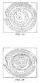
- FIGURES 2A and 2B display the interference fringes (in double pass) of the lens before irradiation and 24 hours post irradiation.
- FIGURE 2A depicts the Fizeau interference fringe (in double pass) of a +20.0 D LAL at best focus preirradiation, the same LAL 24 hours after irradiation at the original best focus position.
- FIGURE 2B depicts the LAL of FIGURES 2A .
- the most striking feature between the two interferograms is the presence of a 3 mm reaction zone in the central portion of the lens, which is from the introduction of defocus. The change corresponds to a -0.70 diopters change in this central region.
- One of the unique aspects of the above described lens is that we have the ability to first change the power of the IOL over the majority of its aperture and then reirradiate the lens over a small zone (0 to 3 mm) to create a bifocal lens as described in example 1.
- a +20.0 D LAL was molded comprising 75 wt% of silicone matrix, 25 wt% of MC, 0.83 wt% PI, and 0.04 wt% UV absorber.
- the lens was initially irradiated using an average intensity of 10 mW/cm 2 using a spatial profile described by equation 2 above.
- the lens was dosed using seven 15 second exposures (5 seconds between each exposure). This treatment induced -1.32 diopters of change in the lens over a 5.5 region of the aperture. Twenty four hours post-irradiation, the lens was reirradiated in the central portion of the lens using the intensity profile represented by equation 1.
- the beam size was reduced to 3 mm in diameter, the average intensity of light was 6 mW/cm 2 and the dose was given in three 30 second doses. Twenty-four hours post irradiation; we observed a change of 1.94 diopters in this central region.
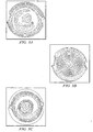
- FIGURE 3A depicts Fizeau interference fringes (in double pass) of a +20.0 D LAL at best focus preirradiation.
- FIGURE 3B depicts the approximately 8 fringes (in double pass) of defocus introduced by the initial irradiation. This procedure introduced -1.32 diopters of change from the initial base power of +20.0 diopters.
- FIGURE 3C depicts the same LAL at the best focus position 24 hours after the initial irradiation. Note the presence of a new focus zone in the central part of the lens. This zone corresponds to +1.94 diopters of change.
- a +20.0 D LAL was molded comprising 75 wt% of silicone matrix, 25 wt% of MC, 0.83 wt% PI, and 0.04 wt% UV absorber.
- the preirradiation Fizeau interference fringes are shown in FIGURE 4A .
- This LAL was then irradiated using two successive, 30-second exposures of 6mW/cm 2 .
- the spatial intensity profile of this initial irradiation is described by equation 2.
- FIGURE 4B -0.5 D of power were removed from the central optical zone of this lens. Twenty-four hours after this initial irradiation, the LAL was irradiated again using two successive, 30-second exposures of 3 mW/cm 2 .
- the second irradiation effectively overlaid on top of the initial dose.
- the spatial intensity profile of this second irradiation is described by equation 1.
- This second irradiation added +0.5 D of power to the initially irradiated region, effectively removing the initial subtraction of power from the LAL and showing an example of multifocal reversibility in the Calhoun Vision LAL.
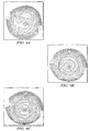
- FIGURES 4A, 4B and 4C depict an example of reversible multifocality.
- FIGURE 4A depicts preirradiation Fizeau interference fringes of a +20.0 diopters LAL at best focus.
- FIGURE 4B Fizeau interference fringes at the preirradiation best focus 24 hours post initial irradiation. Note that -0.5 diopters of spherical power have been subtracted from the central portion of the LAL as noted by the fringes of defocus in the central portion of the LAL.
- FIGURE 4C depicts Fizeau interference fringes at the preirradiation best focus position two hours post the second irradiation showing the removal of the defocus fringes. This indicates that the LAL has been effectively brought back to its preirradiation power.
- FIGURE 5 depicts an example of a lens 500 formed according to embodiments of the invention.
- the lens includes a plurality of different focal zones, 501, 502, 503, 504, 505, and 506. Note that the number of zones is by way of example only, as more or fewer zones could be used.
- the different zones are preferably concentric about a central zone 501.
- the different zones may have different radial widths, e.g. zone 504 has a smaller radial width than zone 503.
- the different zones may have different areas, e.g. the area of zone 501 is smaller than the area of zone 503.
- some or all of the zones may have the same radial width and/or area as other zones.
- Each zone may have a different focal length or diopter than each of the other zones, e.g. zone 502 may be +1.0 diopter with respect to zone 501, and zone 503 may be +1.0 diopter with respect to zone 502, etc.
- some zones may have the same power, while other zones have different powers.
- zones 501, 503, and 505 may have the same power, while zones 502, 504, and 506 may be +1.0 diopter with respect to zone 501.
- zones 501, 503, and 505 may have the same power, while zone 502 may be +1.0 diopter with respect to zone 501, zone 504 may be +1.0 diopter with respect to zone 502, and zone 506 may be +1.0 diopter with respect to zone 504.
- Lens 501 may be a eyeglass lens, a lens used in an optical system, or an intra-ocular lens, as long as the zones are arranged in alternating zones.
Landscapes
- Health & Medical Sciences (AREA)
- Ophthalmology & Optometry (AREA)
- Cardiology (AREA)
- Oral & Maxillofacial Surgery (AREA)
- Transplantation (AREA)
- Engineering & Computer Science (AREA)
- Biomedical Technology (AREA)
- Heart & Thoracic Surgery (AREA)
- Vascular Medicine (AREA)
- Life Sciences & Earth Sciences (AREA)
- Animal Behavior & Ethology (AREA)
- General Health & Medical Sciences (AREA)
- Public Health (AREA)
- Veterinary Medicine (AREA)
- Physics & Mathematics (AREA)
- General Physics & Mathematics (AREA)
- Optics & Photonics (AREA)
- Prostheses (AREA)
- Materials For Medical Uses (AREA)
- Eyeglasses (AREA)
Applications Claiming Priority (7)
| Application Number | Priority Date | Filing Date | Title |
|---|---|---|---|
| US328859 | 1999-06-09 | ||
| US34702801P | 2001-12-28 | 2001-12-28 | |
| US347028P | 2001-12-28 | ||
| US35055102P | 2002-01-22 | 2002-01-22 | |
| US350551P | 2002-01-22 | ||
| US10/328,859 US20030151831A1 (en) | 2001-12-28 | 2002-12-24 | Light adjustable multifocal lenses |
| PCT/US2002/041319 WO2003058296A1 (en) | 2001-12-28 | 2002-12-26 | Light adjustable multifocal lenses |
Publications (3)
| Publication Number | Publication Date |
|---|---|
| EP1459109A1 EP1459109A1 (en) | 2004-09-22 |
| EP1459109A4 EP1459109A4 (en) | 2007-05-02 |
| EP1459109B1 true EP1459109B1 (en) | 2009-08-19 |
Family
ID=27406636
Family Applications (1)
| Application Number | Title | Priority Date | Filing Date |
|---|---|---|---|
| EP02806216A Expired - Lifetime EP1459109B1 (en) | 2001-12-28 | 2002-12-26 | Light adjustable multifocal lenses |
Country Status (9)
| Country | Link |
|---|---|
| US (1) | US20030151831A1 (enExample) |
| EP (1) | EP1459109B1 (enExample) |
| JP (1) | JP2005514646A (enExample) |
| CN (1) | CN1330980C (enExample) |
| AT (1) | ATE440299T1 (enExample) |
| AU (1) | AU2002367370A1 (enExample) |
| DE (1) | DE60233431D1 (enExample) |
| ES (1) | ES2332091T3 (enExample) |
| WO (1) | WO2003058296A1 (enExample) |
Families Citing this family (37)
| Publication number | Priority date | Publication date | Assignee | Title |
|---|---|---|---|---|
| US20050099597A1 (en) * | 2002-12-24 | 2005-05-12 | Calhoun Vision | Light adjustable multifocal lenses |
| US7281795B2 (en) | 1999-01-12 | 2007-10-16 | Calhoun Vision, Inc. | Light adjustable multifocal lenses |
| WO2000052516A2 (en) | 1999-03-01 | 2000-09-08 | Boston Innovative Optics, Inc. | System and method for increasing the depth of focus of the human eye |
| US20070031473A1 (en) * | 2005-08-05 | 2007-02-08 | Peyman Gholam A | Drug delivery system and method |
| US8162927B2 (en) * | 2000-03-21 | 2012-04-24 | Gholam A. Peyman | Method and apparatus for accommodating intraocular lens |
| US20050113911A1 (en) * | 2002-10-17 | 2005-05-26 | Peyman Gholam A. | Adjustable intraocular lens for insertion into the capsular bag |
| US6949093B1 (en) * | 2000-03-21 | 2005-09-27 | Minu, L.L.C. | Adjustable universal implant blank for modifying corneal curvature and methods of modifying corneal curvature therewith |
| US7293871B2 (en) * | 2000-11-27 | 2007-11-13 | Ophthonix, Inc. | Apparatus and method of correcting higher-order aberrations of the human eye |
| US20050182489A1 (en) * | 2001-04-27 | 2005-08-18 | Peyman Gholam A. | Intraocular lens adapted for adjustment via laser after implantation |
| US7217375B2 (en) | 2001-06-04 | 2007-05-15 | Ophthonix, Inc. | Apparatus and method of fabricating a compensating element for wavefront correction using spatially localized curing of resin mixtures |
| US9119710B2 (en) * | 2005-09-08 | 2015-09-01 | Calhoun Vision, Inc. | Adjustable optical elements with enhanced ultraviolet protection |
| US9681800B2 (en) | 2005-10-27 | 2017-06-20 | The Arizona Board Of Regents On Behalf Of The University Of Arizona | Holographic adaptive see-through phoropter |
| US20070100443A1 (en) * | 2005-10-27 | 2007-05-03 | Peyman Gholam A | Intraocular lens adapted for accommodation via electrical signals |
| US20080103592A1 (en) * | 2006-10-30 | 2008-05-01 | Calhoun Vision, Inc. | Piggyback lenses |
| US20080269889A1 (en) * | 2007-04-30 | 2008-10-30 | Simpson Michael J | Haptic Junction Designs to Reduce Negative Dysphotopsia |
| US20080269885A1 (en) * | 2007-04-30 | 2008-10-30 | Simpson Michael J | IOL Peripheral Surface Designs to Reduce Negative Dysphotopsia |
| US10254562B2 (en) * | 2008-04-04 | 2019-04-09 | Battelle Memorial Institute | Methods for tailoring the refractive index of lenses |
| EP2537061B1 (en) * | 2010-02-17 | 2017-12-20 | Akkolens International B.V. | Adjustable chiral ophthalmic lens |
| US11135052B2 (en) * | 2011-09-16 | 2021-10-05 | Rxsight, Inc. | Method of adjusting a blended extended depth of focus light adjustable lens with laterally offset axes |
| US10874505B2 (en) | 2011-09-16 | 2020-12-29 | Rxsight, Inc. | Using the light adjustable lens (LAL) to increase the depth of focus by inducing targeted amounts of asphericity |
| US11191637B2 (en) | 2011-09-16 | 2021-12-07 | Rxsight, Inc. | Blended extended depth of focus light adjustable lens with laterally offset axes |
| WO2013082545A1 (en) | 2011-12-02 | 2013-06-06 | Acufocus, Inc. | Ocular mask having selective spectral transmission |
| US8900300B1 (en) | 2012-02-22 | 2014-12-02 | Omega Ophthalmics Llc | Prosthetic capsular bag and method of inserting the same |
| US9204962B2 (en) | 2013-03-13 | 2015-12-08 | Acufocus, Inc. | In situ adjustable optical mask |
| US9427922B2 (en) | 2013-03-14 | 2016-08-30 | Acufocus, Inc. | Process for manufacturing an intraocular lens with an embedded mask |
| CN104656271A (zh) * | 2013-11-22 | 2015-05-27 | 褚仁远 | 镜片及包括其的眼镜 |
| EP3157466B1 (en) | 2014-06-19 | 2022-03-16 | Omega Ophthalmics LLC | Prosthetic capsular system |
| US9358103B1 (en) | 2015-02-10 | 2016-06-07 | Omega Ophthalmics Llc | Prosthetic capsular devices, systems, and methods |
| US11103344B2 (en) * | 2015-11-09 | 2021-08-31 | Hoya Corporation | Optical devices having partial or incomplete optic and associated methods |
| WO2017213980A1 (en) | 2016-06-06 | 2017-12-14 | Omega Ophthalmics Llc | Prosthetic capsular devices, systems, and methods |
| US10274750B2 (en) | 2016-07-21 | 2019-04-30 | National Taiwan University Of Science And Technology | Progressive multifocal contact lens and producing method thereof |
| TWI584022B (zh) * | 2016-07-21 | 2017-05-21 | 國立臺灣科技大學 | 漸近變焦隱形眼鏡及其製造方法 |
| WO2018075932A1 (en) | 2016-10-21 | 2018-04-26 | Omega Ophthalmics Llc | Prosthetic capsular devices, systems, and methods |
| CA3095098A1 (en) | 2018-04-06 | 2019-10-10 | Omega Ophthalmics Llc | Prosthetic capsular devices, systems, and methods |
| AU2021283398A1 (en) | 2020-06-01 | 2023-01-05 | Icares Medicus, Inc. | Double-sided aspheric diffractive multifocal lens, manufacture, and uses thereof |
| EP4225211A4 (en) | 2020-10-12 | 2024-10-30 | Omega Ophthalmics LLC | PROSTHETIC CAPSULAR DEVICES, SYSTEMS AND METHODS |
| CN213423626U (zh) * | 2020-12-03 | 2021-06-11 | 睛彩国际股份有限公司 | 一种新型隐形眼镜 |
Family Cites Families (17)
| Publication number | Priority date | Publication date | Assignee | Title |
|---|---|---|---|---|
| US4608050A (en) * | 1983-07-21 | 1986-08-26 | Innovative Surgical Products, Inc. | Correction of defects in the eye and compositions therefor |
| US4787903A (en) * | 1985-07-24 | 1988-11-29 | Grendahl Dennis T | Intraocular lens |
| US5225858A (en) * | 1987-06-01 | 1993-07-06 | Valdemar Portney | Multifocal ophthalmic lens |
| FR2657294B1 (fr) * | 1990-01-22 | 1992-11-27 | Essilor Int | Procede pour la fabrication d'une lentille optique artificielle, et lentille optique artificielle correspondante. |
| US5066301A (en) * | 1990-10-09 | 1991-11-19 | Wiley Robert G | Variable focus lens |
| US5288293A (en) * | 1992-09-24 | 1994-02-22 | Donnell Jr Francis E O | In vivo modification of refractive power of an intraocular lens implant |
| US5443506A (en) * | 1992-11-18 | 1995-08-22 | Garabet; Antoine L. | Lens with variable optical properties |
| ES2139739T3 (es) * | 1993-04-07 | 2000-02-16 | Ttp Group Plc | Lente conmutable. |
| US5728155A (en) * | 1996-01-22 | 1998-03-17 | Quantum Solutions, Inc. | Adjustable intraocular lens |
| US5728156A (en) * | 1996-08-06 | 1998-03-17 | Prism Opthalmics, L.L.C. | Prismatic intraocular lenses and related methods of in situ alteration of their optical characteristics |
| US5997140A (en) * | 1997-12-29 | 1999-12-07 | Novartis Ag | Actively controllable multifocal lens |
| US6450642B1 (en) * | 1999-01-12 | 2002-09-17 | California Institute Of Technology | Lenses capable of post-fabrication power modification |
| US6491391B1 (en) * | 1999-07-02 | 2002-12-10 | E-Vision Llc | System, apparatus, and method for reducing birefringence |
| US6250757B1 (en) * | 1999-12-15 | 2001-06-26 | Johnson & Johnson Vision Products, Inc. | Hybrid refractive birefringent multifocal ophthalmic lenses |
| WO2001071411A2 (en) * | 2000-03-20 | 2001-09-27 | California Institute Of Technology | Application of wavefront sensor to lenses capable of post-fabrication power modification |
| US7293871B2 (en) * | 2000-11-27 | 2007-11-13 | Ophthonix, Inc. | Apparatus and method of correcting higher-order aberrations of the human eye |
| US6712466B2 (en) * | 2001-10-25 | 2004-03-30 | Ophthonix, Inc. | Eyeglass manufacturing method using variable index layer |
-
2002
- 2002-12-24 US US10/328,859 patent/US20030151831A1/en not_active Abandoned
- 2002-12-26 WO PCT/US2002/041319 patent/WO2003058296A1/en not_active Ceased
- 2002-12-26 AT AT02806216T patent/ATE440299T1/de not_active IP Right Cessation
- 2002-12-26 ES ES02806216T patent/ES2332091T3/es not_active Expired - Lifetime
- 2002-12-26 DE DE60233431T patent/DE60233431D1/de not_active Expired - Lifetime
- 2002-12-26 AU AU2002367370A patent/AU2002367370A1/en not_active Abandoned
- 2002-12-26 CN CNB028279867A patent/CN1330980C/zh not_active Expired - Lifetime
- 2002-12-26 EP EP02806216A patent/EP1459109B1/en not_active Expired - Lifetime
- 2002-12-26 JP JP2003558551A patent/JP2005514646A/ja active Pending
Also Published As
| Publication number | Publication date |
|---|---|
| ES2332091T3 (es) | 2010-01-26 |
| JP2005514646A (ja) | 2005-05-19 |
| EP1459109A1 (en) | 2004-09-22 |
| DE60233431D1 (de) | 2009-10-01 |
| EP1459109A4 (en) | 2007-05-02 |
| AU2002367370A1 (en) | 2003-07-24 |
| CN1330980C (zh) | 2007-08-08 |
| CN1618030A (zh) | 2005-05-18 |
| ATE440299T1 (de) | 2009-09-15 |
| WO2003058296A1 (en) | 2003-07-17 |
| US20030151831A1 (en) | 2003-08-14 |
Similar Documents
| Publication | Publication Date | Title |
|---|---|---|
| EP1459109B1 (en) | Light adjustable multifocal lenses | |
| US20050099597A1 (en) | Light adjustable multifocal lenses | |
| US7988285B2 (en) | Light adjustable multifocal lenses | |
| US10010406B2 (en) | Using the light adjustable lens (LAL) to increase the depth of focus by inducing targeted amounts of asphericity | |
| US7134755B2 (en) | Customized lenses | |
| US6450642B1 (en) | Lenses capable of post-fabrication power modification | |
| US11135052B2 (en) | Method of adjusting a blended extended depth of focus light adjustable lens with laterally offset axes | |
| Zeng et al. | Advances and challenges of intraocular lens design | |
| US11191637B2 (en) | Blended extended depth of focus light adjustable lens with laterally offset axes | |
| WO2020146177A2 (en) | Method of adjusting a blended extended depth of focus light adjustable lens with laterally offset axes | |
| AU2002360662B2 (en) | Customized lenses |
Legal Events
| Date | Code | Title | Description |
|---|---|---|---|
| PUAI | Public reference made under article 153(3) epc to a published international application that has entered the european phase |
Free format text: ORIGINAL CODE: 0009012 |
|
| 17P | Request for examination filed |
Effective date: 20040624 |
|
| AK | Designated contracting states |
Kind code of ref document: A1 Designated state(s): AT BE BG CH CY CZ DE DK EE ES FI FR GB GR IE IT LI LU MC NL PT SE SI SK TR |
|
| AX | Request for extension of the european patent |
Extension state: AL LT LV MK RO |
|
| A4 | Supplementary search report drawn up and despatched |
Effective date: 20070329 |
|
| 17Q | First examination report despatched |
Effective date: 20070817 |
|
| GRAP | Despatch of communication of intention to grant a patent |
Free format text: ORIGINAL CODE: EPIDOSNIGR1 |
|
| GRAS | Grant fee paid |
Free format text: ORIGINAL CODE: EPIDOSNIGR3 |
|
| GRAA | (expected) grant |
Free format text: ORIGINAL CODE: 0009210 |
|
| AK | Designated contracting states |
Kind code of ref document: B1 Designated state(s): AT BE BG CH CY CZ DE DK EE ES FI FR GB GR IE IT LI LU MC NL PT SE SI SK TR |
|
| REG | Reference to a national code |
Ref country code: GB Ref legal event code: FG4D |
|
| REG | Reference to a national code |
Ref country code: CH Ref legal event code: EP |
|
| REG | Reference to a national code |
Ref country code: IE Ref legal event code: FG4D |
|
| REF | Corresponds to: |
Ref document number: 60233431 Country of ref document: DE Date of ref document: 20091001 Kind code of ref document: P |
|
| REG | Reference to a national code |
Ref country code: ES Ref legal event code: FG2A Ref document number: 2332091 Country of ref document: ES Kind code of ref document: T3 |
|
| PG25 | Lapsed in a contracting state [announced via postgrant information from national office to epo] |
Ref country code: SE Free format text: LAPSE BECAUSE OF FAILURE TO SUBMIT A TRANSLATION OF THE DESCRIPTION OR TO PAY THE FEE WITHIN THE PRESCRIBED TIME-LIMIT Effective date: 20090819 Ref country code: FI Free format text: LAPSE BECAUSE OF FAILURE TO SUBMIT A TRANSLATION OF THE DESCRIPTION OR TO PAY THE FEE WITHIN THE PRESCRIBED TIME-LIMIT Effective date: 20090819 Ref country code: AT Free format text: LAPSE BECAUSE OF FAILURE TO SUBMIT A TRANSLATION OF THE DESCRIPTION OR TO PAY THE FEE WITHIN THE PRESCRIBED TIME-LIMIT Effective date: 20090819 |
|
| NLV1 | Nl: lapsed or annulled due to failure to fulfill the requirements of art. 29p and 29m of the patents act | ||
| PG25 | Lapsed in a contracting state [announced via postgrant information from national office to epo] |
Ref country code: SI Free format text: LAPSE BECAUSE OF FAILURE TO SUBMIT A TRANSLATION OF THE DESCRIPTION OR TO PAY THE FEE WITHIN THE PRESCRIBED TIME-LIMIT Effective date: 20090819 Ref country code: NL Free format text: LAPSE BECAUSE OF FAILURE TO SUBMIT A TRANSLATION OF THE DESCRIPTION OR TO PAY THE FEE WITHIN THE PRESCRIBED TIME-LIMIT Effective date: 20090819 |
|
| PG25 | Lapsed in a contracting state [announced via postgrant information from national office to epo] |
Ref country code: CY Free format text: LAPSE BECAUSE OF FAILURE TO SUBMIT A TRANSLATION OF THE DESCRIPTION OR TO PAY THE FEE WITHIN THE PRESCRIBED TIME-LIMIT Effective date: 20090819 Ref country code: BG Free format text: LAPSE BECAUSE OF FAILURE TO SUBMIT A TRANSLATION OF THE DESCRIPTION OR TO PAY THE FEE WITHIN THE PRESCRIBED TIME-LIMIT Effective date: 20091119 Ref country code: PT Free format text: LAPSE BECAUSE OF FAILURE TO SUBMIT A TRANSLATION OF THE DESCRIPTION OR TO PAY THE FEE WITHIN THE PRESCRIBED TIME-LIMIT Effective date: 20091221 |
|
| PG25 | Lapsed in a contracting state [announced via postgrant information from national office to epo] |
Ref country code: EE Free format text: LAPSE BECAUSE OF FAILURE TO SUBMIT A TRANSLATION OF THE DESCRIPTION OR TO PAY THE FEE WITHIN THE PRESCRIBED TIME-LIMIT Effective date: 20090819 Ref country code: DK Free format text: LAPSE BECAUSE OF FAILURE TO SUBMIT A TRANSLATION OF THE DESCRIPTION OR TO PAY THE FEE WITHIN THE PRESCRIBED TIME-LIMIT Effective date: 20090819 Ref country code: CZ Free format text: LAPSE BECAUSE OF FAILURE TO SUBMIT A TRANSLATION OF THE DESCRIPTION OR TO PAY THE FEE WITHIN THE PRESCRIBED TIME-LIMIT Effective date: 20090819 |
|
| PG25 | Lapsed in a contracting state [announced via postgrant information from national office to epo] |
Ref country code: SK Free format text: LAPSE BECAUSE OF FAILURE TO SUBMIT A TRANSLATION OF THE DESCRIPTION OR TO PAY THE FEE WITHIN THE PRESCRIBED TIME-LIMIT Effective date: 20090819 |
|
| PLBE | No opposition filed within time limit |
Free format text: ORIGINAL CODE: 0009261 |
|
| STAA | Information on the status of an ep patent application or granted ep patent |
Free format text: STATUS: NO OPPOSITION FILED WITHIN TIME LIMIT |
|
| PG25 | Lapsed in a contracting state [announced via postgrant information from national office to epo] |
Ref country code: BE Free format text: LAPSE BECAUSE OF FAILURE TO SUBMIT A TRANSLATION OF THE DESCRIPTION OR TO PAY THE FEE WITHIN THE PRESCRIBED TIME-LIMIT Effective date: 20090819 |
|
| 26N | No opposition filed |
Effective date: 20100520 |
|
| PG25 | Lapsed in a contracting state [announced via postgrant information from national office to epo] |
Ref country code: MC Free format text: LAPSE BECAUSE OF NON-PAYMENT OF DUE FEES Effective date: 20100701 |
|
| REG | Reference to a national code |
Ref country code: CH Ref legal event code: PL |
|
| PG25 | Lapsed in a contracting state [announced via postgrant information from national office to epo] |
Ref country code: GR Free format text: LAPSE BECAUSE OF FAILURE TO SUBMIT A TRANSLATION OF THE DESCRIPTION OR TO PAY THE FEE WITHIN THE PRESCRIBED TIME-LIMIT Effective date: 20091120 Ref country code: LI Free format text: LAPSE BECAUSE OF NON-PAYMENT OF DUE FEES Effective date: 20091231 Ref country code: IE Free format text: LAPSE BECAUSE OF NON-PAYMENT OF DUE FEES Effective date: 20091226 Ref country code: CH Free format text: LAPSE BECAUSE OF NON-PAYMENT OF DUE FEES Effective date: 20091231 |
|
| PG25 | Lapsed in a contracting state [announced via postgrant information from national office to epo] |
Ref country code: LU Free format text: LAPSE BECAUSE OF NON-PAYMENT OF DUE FEES Effective date: 20091226 |
|
| PG25 | Lapsed in a contracting state [announced via postgrant information from national office to epo] |
Ref country code: TR Free format text: LAPSE BECAUSE OF FAILURE TO SUBMIT A TRANSLATION OF THE DESCRIPTION OR TO PAY THE FEE WITHIN THE PRESCRIBED TIME-LIMIT Effective date: 20090819 |
|
| REG | Reference to a national code |
Ref country code: FR Ref legal event code: PLFP Year of fee payment: 14 |
|
| PGFP | Annual fee paid to national office [announced via postgrant information from national office to epo] |
Ref country code: FR Payment date: 20151231 Year of fee payment: 14 |
|
| REG | Reference to a national code |
Ref country code: FR Ref legal event code: ST Effective date: 20160831 |
|
| PG25 | Lapsed in a contracting state [announced via postgrant information from national office to epo] |
Ref country code: FR Free format text: LAPSE BECAUSE OF NON-PAYMENT OF DUE FEES Effective date: 20151231 |
|
| PG25 | Lapsed in a contracting state [announced via postgrant information from national office to epo] |
Ref country code: IT Free format text: LAPSE BECAUSE OF NON-PAYMENT OF DUE FEES Effective date: 20151226 |
|
| PG25 | Lapsed in a contracting state [announced via postgrant information from national office to epo] |
Ref country code: IT Free format text: LAPSE BECAUSE OF NON-PAYMENT OF DUE FEES Effective date: 20151226 |
|
| PGRI | Patent reinstated in contracting state [announced from national office to epo] |
Ref country code: IT Effective date: 20170816 |
|
| REG | Reference to a national code |
Ref country code: DE Ref legal event code: R082 Ref document number: 60233431 Country of ref document: DE Representative=s name: MUELLER-BORE & PARTNER PATENTANWAELTE PARTG MB, DE Ref country code: DE Ref legal event code: R081 Ref document number: 60233431 Country of ref document: DE Owner name: RXSIGHT, INC., ALISO VIEJO, US Free format text: FORMER OWNER: CALHOUN VISION INC., PASADENA, CALIF., US |
|
| PGFP | Annual fee paid to national office [announced via postgrant information from national office to epo] |
Ref country code: DE Payment date: 20211102 Year of fee payment: 20 Ref country code: GB Payment date: 20211104 Year of fee payment: 20 |
|
| PGFP | Annual fee paid to national office [announced via postgrant information from national office to epo] |
Ref country code: IT Payment date: 20211110 Year of fee payment: 20 |
|
| PGFP | Annual fee paid to national office [announced via postgrant information from national office to epo] |
Ref country code: ES Payment date: 20220104 Year of fee payment: 20 |
|
| REG | Reference to a national code |
Ref country code: DE Ref legal event code: R071 Ref document number: 60233431 Country of ref document: DE |
|
| REG | Reference to a national code |
Ref country code: GB Ref legal event code: PE20 Expiry date: 20221225 |
|
| PG25 | Lapsed in a contracting state [announced via postgrant information from national office to epo] |
Ref country code: GB Free format text: LAPSE BECAUSE OF EXPIRATION OF PROTECTION Effective date: 20221225 |
|
| REG | Reference to a national code |
Ref country code: ES Ref legal event code: FD2A Effective date: 20230428 |
|
| PG25 | Lapsed in a contracting state [announced via postgrant information from national office to epo] |
Ref country code: ES Free format text: LAPSE BECAUSE OF EXPIRATION OF PROTECTION Effective date: 20221227 |