EP1458296B1 - Ligature device for body parts - Google Patents
Ligature device for body parts Download PDFInfo
- Publication number
- EP1458296B1 EP1458296B1 EP02792896A EP02792896A EP1458296B1 EP 1458296 B1 EP1458296 B1 EP 1458296B1 EP 02792896 A EP02792896 A EP 02792896A EP 02792896 A EP02792896 A EP 02792896A EP 1458296 B1 EP1458296 B1 EP 1458296B1
- Authority
- EP
- European Patent Office
- Prior art keywords
- ligature
- wall
- retaining
- intermediate wall
- upper side
- Prior art date
- Legal status (The legal status is an assumption and is not a legal conclusion. Google has not performed a legal analysis and makes no representation as to the accuracy of the status listed.)
- Expired - Lifetime
Links
- 238000003780 insertion Methods 0.000 claims description 10
- 230000037431 insertion Effects 0.000 claims description 10
- 230000000717 retained effect Effects 0.000 claims 1
- 238000010276 construction Methods 0.000 abstract description 2
- 238000000926 separation method Methods 0.000 abstract 1
- 210000002105 tongue Anatomy 0.000 description 4
- 238000005192 partition Methods 0.000 description 2
- 230000007704 transition Effects 0.000 description 2
- 230000001154 acute effect Effects 0.000 description 1
- 230000000295 complement effect Effects 0.000 description 1
- 239000012141 concentrate Substances 0.000 description 1
- 230000000881 depressing effect Effects 0.000 description 1
- 238000001514 detection method Methods 0.000 description 1
- 230000002349 favourable effect Effects 0.000 description 1
- 230000013011 mating Effects 0.000 description 1
Images


Classifications
-
- A—HUMAN NECESSITIES
- A61—MEDICAL OR VETERINARY SCIENCE; HYGIENE
- A61B—DIAGNOSIS; SURGERY; IDENTIFICATION
- A61B17/00—Surgical instruments, devices or methods, e.g. tourniquets
- A61B17/12—Surgical instruments, devices or methods, e.g. tourniquets for ligaturing or otherwise compressing tubular parts of the body, e.g. blood vessels, umbilical cord
- A61B17/132—Tourniquets
- A61B17/1322—Tourniquets comprising a flexible encircling member
- A61B17/1327—Tensioning clamps
-
- Y—GENERAL TAGGING OF NEW TECHNOLOGICAL DEVELOPMENTS; GENERAL TAGGING OF CROSS-SECTIONAL TECHNOLOGIES SPANNING OVER SEVERAL SECTIONS OF THE IPC; TECHNICAL SUBJECTS COVERED BY FORMER USPC CROSS-REFERENCE ART COLLECTIONS [XRACs] AND DIGESTS
- Y10—TECHNICAL SUBJECTS COVERED BY FORMER USPC
- Y10T—TECHNICAL SUBJECTS COVERED BY FORMER US CLASSIFICATION
- Y10T24/00—Buckles, buttons, clasps, etc.
- Y10T24/40—Buckles
- Y10T24/4002—Harness
- Y10T24/4012—Clamping
- Y10T24/4016—Pivoted part or lever
-
- Y—GENERAL TAGGING OF NEW TECHNOLOGICAL DEVELOPMENTS; GENERAL TAGGING OF CROSS-SECTIONAL TECHNOLOGIES SPANNING OVER SEVERAL SECTIONS OF THE IPC; TECHNICAL SUBJECTS COVERED BY FORMER USPC CROSS-REFERENCE ART COLLECTIONS [XRACs] AND DIGESTS
- Y10—TECHNICAL SUBJECTS COVERED BY FORMER USPC
- Y10T—TECHNICAL SUBJECTS COVERED BY FORMER US CLASSIFICATION
- Y10T24/00—Buckles, buttons, clasps, etc.
- Y10T24/45—Separable-fastener or required component thereof [e.g., projection and cavity to complete interlock]
- Y10T24/45225—Separable-fastener or required component thereof [e.g., projection and cavity to complete interlock] including member having distinct formations and mating member selectively interlocking therewith
- Y10T24/45471—Projection having movable connection between components thereof or variable configuration
- Y10T24/45524—Projection having movable connection between components thereof or variable configuration including resiliently biased projection component or surface segment
Definitions
- the invention relates to a Abschnürvorraum for body parts with a lock housing having a bottom wall, two side walls and on its top a top wall, with a releasably coupled at one end to the lock housing by means of a insertable from the back between an intermediate wall and the top wall locking shoe or connectable Abschnürband that guided to form a loop with its other free end between a rocker pivotally mounted above the bottom wall and a distance above arranged intermediate wall through the lock housing or feasible and with the rocker against a front, connected to the lock housing portion of the partition can be clamped.
- Such a tourniquet device is disclosed in DE 42 10 255 C1 and also in DE 94 18 598 U1.
- a rocker is pivotally mounted on the front in a convex passes over the top and rear guided operating portion and in the transition region a lead-through opening 4.3 for taking out a running above the rocker Abschnürbandes, which forms a loop around the deliberatelyschnürende body part loop on the back of the lock housing and inserted with a locking shoe in a receiving shaft on the back of the housing is and is locked.
- the Abschnürband is pressed and clamped against the underside of a partition wall disposed between the bottom wall and a top wall and clamped when the rear portion of the rocker is drawn in the constriction down to the bottom wall.
- the locking shoe has an upwardly projecting and on the underside of the top wall supporting latching tongue, which is pressed by means of an above arranged, separate pressure member for unlatching and pulling out of the locking shoe with the respective Schnschnbandende down.
- the invention has for its object to provide a pinch-off device of the type mentioned, which offers advantages in terms of structure and handling.
- the intermediate wall has a projecting to the top resilient portion with which the locking shoe is raised in its rear region and pressed in the inserted state with its rear top against a fixed housing abutment, wherein the locking shoe with a back holding element and / or a front holding part in cooperation with a counter element or counterpart of the lock housing against pulling out held back and released by depressing its rear area.
- the locking shoe for insertion into the lock housing has a plug-in section and is provided for releasing with an operating section connected to its rear side, then the locking shoe can be plugged in and released in a simple manner, the simple structure being favored.
- the operation is facilitated by the fact that the actuating portion is provided on its upper side with a triggering trough and that in him a fixing receptacle for fixing the Abschnürbandes is formed so that the operator can concentrate completely on their actual task.
- the intermediate wall is integrally formed with its front portion on both sides of the inside of the adjacent side walls, while its rear portion with a respective Gap is separated from the adjacent side walls or integrally formed webs of the intermediate wall.
- the measures are further advantageous that the locking shoe on the underside of its front portion as a holding part has a downwardly projecting retaining lug or recess with retaining shoulder, wherein the lower side retaining lug with a retaining edge or the recess with a holding projection on the top the front portion of the intermediate wall cooperates.
- the rear retaining element is formed on the upper side of the locking shoe as upwardly projecting retaining lug or as a recess, wherein the upper side retaining lug or depression cooperates with a support portion having a counter element.
- a secure operation of the tourniquet is further supported by the fact that the intermediate wall for clamping the Abschnürbandes by means of the rocker on its underside at the front edge has a downwardly advanced, acute-angled retaining edge as a clamping structure, which is employed against retraction of Abschnürbandes.
- an advantageous embodiment for the construction and handling that the recess has lateral, open to the rear guide grooves into which the insert is inserted, and that the contour of a rear edge of the insert in the inserted state with the contour of the rear edge of Cover wall of the lock housing is flush and that the contour of the front of the actuating portion is adapted to the contour of the rear edge of the insert part and the top wall.
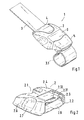
- An entangling device 1 shown in Fig. 1 has as essential components a lock housing 2, a guided by this, on the rear side of the lock housing 2 to form a loop 3.1 by means of a locking shoe 5 releasably fixed Abschnürband 3 and a dosable clamping the Abschnürbands 3 in the lock housing 2 arranged rocker 4 on.
- a top wall 2.4 of the lock housing 2 On the top of a top wall 2.4 of the lock housing 2 is in an appropriately trained recess 2.3 an insert 6 z. B. used as information plaque, as shown in connection with FIG. 2.
- the lock housing 2 shown in more detail in Fig. 2 is bounded by two side walls 2.6 with respective recessed grips 2.7, a bottom wall 2.8 and a top wall 2.4 and has on its back an insertion for the Abschnürband 3 and the locking shoe 5 and the insert 6 on.
- the lock housing 2 On its front side, the lock housing 2 is provided with an opening 2.1, in which the rocker 4 can be used and out of which the Abschnürband 3 is led out with its one end.
- the recess 2.3 is delimited on its underside with a wall section 2.31, in which a trained as a rectangular window holding section is provided 2.32, and has lateral guide grooves for insertion of the insert part 6 from the back 2.2 from, the guide grooves between the wall section 2.31 and mutual Sections of the top wall 2.4 and the groove bottom forming portions of the side walls 2.6 are formed. Also in the front region of the recess 2.3, it may be formed like a groove to also accommodate a front edge 6.3 of the insert part 6 (see Fig. 6) in the fully inserted state.
- the intermediate wall 2.9 has on its underside a holding structure for clamping the Abschnürbands 3 and is formed at an acute angle, in particular at its front lower edge 2.91, resulting in a certain employment against the pulling direction of the Abschnürbands 3 in pinch-off.
- the front upper edge forms a retaining edge 2.92 as a retaining lug for a hook-shaped holding part 5.12 on the underside of the plug section 5.1 of the locking shoe 5.
- a resilient section 2.93 formed by lateral incisions or column 2.94 with respect to lateral, connected to the side walls 2.6 sections of the intermediate wall 2.9.
- the intermediate wall 2.9 is continuously connected to the side walls 2.6, in particular integrally formed.
- a rib-like pivot support 2.81 is formed as a pivot bearing and for holding the rocker 4, as Figs. 3b), 3c) and 3d) can also recognize.
- rocker 4 Details of the rocker 4 are shown in Fig. 4a) to d).
- a passage opening 4.3 is formed for the Abschnürband 3.
- the pivot bearing is 4.11 limited on its rear side by means of downwardly projecting spring tongues 4.12 with a rearwardly extending insertion, so that the rocker 4 from the front easily under guidance in lateral grooves or similar guideways in the feedthrough 2.10 of the lock housing inserted and locked on the swivel support 2.81 and can be released again by means of the spring tongues 4.12.
- the operating section 4.2 is tongue-like in plan view and tapers upwardly in the form of a continuous curvature and fitted in a correspondingly shaped recess in the top wall 2.4 of the lock housing 2.
- the locking shoe 5 shown in more detail in Fig. 5a) to d) has in its rear region an integrally formed on the plug portion 5.1, in the inserted state to the rear over the lock housing 2 projecting operating section 5.2 with an upwardly concave trigger trough 5.22 on its top.
- the front edge of the actuating portion 5.2 is symmetrically curved in plan view with two over a central curve portion continuously merging into each other laterally convex curved portions and to a corresponding contour the rear edge of the top wall 2.4 of the lock housing 2 adapted so that there is a clear fit in the inserted state.
- the operating section 5.2 is provided with a fixing receptacle 5.3 open to the rear for receiving a fixing part 7 with counterpart 8 (see Fig.
- the integrally formed on the operating section 5.2, forward subsequent mating section 5.1 is provided in its rear edge region with an upwardly projecting holding element 5.11, with which the locking shoe 5 is supported in the inserted state at the rear edge of the holding section 2.32 in the wall section 2.31 of the lock housing 2 , wherein the locking shoe 5 is pressed by means of the rear, resilient portion of the intermediate wall 2.9 upwards.
- the already mentioned holding part hooks 5.12 on the underside of the front portion of the plug-in section 5.1 at the front retaining edge 2.92 of the intermediate wall 2.9.
- the insert 6 shown in more detail in Fig. 6 preferably has in cross-section conical lateral edges 6.2 and a complementary to the front edge of the actuating portion 5.2 of the locking shoe extending rear edge 6.2 and is with a certain clamping action, but pushed out by hand in the recess 2.3 held.
- the insert 6 can be designed to be identified in a desired color or transparent to underlay with information, such as a name badge, or even wear a suitable inscription.
- the fixing part shown in Fig. 7a) to d) has a fixing plate 7.1 with fixing 7.11 in the form of openings and on its front downwardly projecting hook part 7.12 and goes on its back in an integrally formed fixing block 7.2.
- fixing 7.11 in the form of openings and on its front downwardly projecting hook part 7.12 and goes on its back in an integrally formed fixing block 7.2.
Landscapes
- Health & Medical Sciences (AREA)
- Surgery (AREA)
- Life Sciences & Earth Sciences (AREA)
- Molecular Biology (AREA)
- General Health & Medical Sciences (AREA)
- Vascular Medicine (AREA)
- Engineering & Computer Science (AREA)
- Biomedical Technology (AREA)
- Heart & Thoracic Surgery (AREA)
- Medical Informatics (AREA)
- Reproductive Health (AREA)
- Animal Behavior & Ethology (AREA)
- Nuclear Medicine, Radiotherapy & Molecular Imaging (AREA)
- Public Health (AREA)
- Veterinary Medicine (AREA)
- Buckles (AREA)
- Surgical Instruments (AREA)
- Prostheses (AREA)
- Footwear And Its Accessory, Manufacturing Method And Apparatuses (AREA)
- Orthopedics, Nursing, And Contraception (AREA)
- Dental Tools And Instruments Or Auxiliary Dental Instruments (AREA)
Abstract
Description
Die Erfindung bezieht sich auf eine Abschnürvorrichtung für Körperteile mit einem Schlossgehäuse, das eine Bodenwand, zwei Seitenwände und auf seiner Oberseite eine Deckwand aufweist, mit einem mit einem Ende am Schlossgehäuse mittels eines von der Rückseite her zwischen einer Zwischenwand und der Deckwand einführbaren Rastschuhs lösbar angekoppelten oder ankoppelbaren Abschnürband, das unter Bildung einer Schlaufe mit seinem anderen freien Ende zwischen einer über der Bodenwand schwenkbar gelagerten Wippe und einer unter Abstand darüber angeordneten Zwischenwand durch das Schlossgehäuse geführt oder führbar und mit der Wippe gegen einen vorderen, mit dem Schlossgehäuse verbundenen Abschnitt der Zwischenwand einklemmbar ist.The invention relates to a Abschnürvorrichtung for body parts with a lock housing having a bottom wall, two side walls and on its top a top wall, with a releasably coupled at one end to the lock housing by means of a insertable from the back between an intermediate wall and the top wall locking shoe or connectable Abschnürband that guided to form a loop with its other free end between a rocker pivotally mounted above the bottom wall and a distance above arranged intermediate wall through the lock housing or feasible and with the rocker against a front, connected to the lock housing portion of the partition can be clamped.
Eine derartige Abschnürvorrichtung ist in der DE 42 10 255 C1 und auch der DE 94 18 598 U1 angegeben. Oberhalb einer Bodenwand des Schlossgehäuses ist eine Wippe schwenkbar gelagert, die auf ihrer Vorderseite in einen konvex nach oben und hinten geführten Betätigungsabschnitt übergeht und in dem Übergangsbereich eine Durchführöffnung 4.3 zum Herausführen eines oberhalb der Wippe verlaufenden Abschnürbandes aufweist, das auf der Rückseite des Schlossgehäuses eine um das abzuschnürende Körperteil legbare Schlaufe bildet und mit einem Rastschuh in einen Aufnahmeschacht auf der Rückseite des Gehäuses eingeführt ist und verrastet ist. Mittels eines vorderen Abschnitts der Wippe wird das Abschnürband gegen die Unterseite einer zwischen der Bodenwand und einer Deckwand angeordneten Zwischenwand gedrückt und eingeklemmt, wenn der hintere Abschnitt der Wippe beim Abschnüren nach unten zu der Bodenwand hin gezogen wird. Der Rastschuh weist eine nach oben abstehende und auf der Unterseite der Deckwand sich abstützende Rastzunge auf, die mittels eines darüber angeordneten, separaten Druckteils zum Entrasten und Herausziehen des Rastschuhs mit dem betreffenden Abschnürbandende nach unten drückbar ist.Such a tourniquet device is disclosed in DE 42 10 255 C1 and also in DE 94 18 598 U1. Above a bottom wall of the lock housing, a rocker is pivotally mounted on the front in a convex passes over the top and rear guided operating portion and in the transition region a lead-through opening 4.3 for taking out a running above the rocker Abschnürbandes, which forms a loop around the auszuschnürende body part loop on the back of the lock housing and inserted with a locking shoe in a receiving shaft on the back of the housing is and is locked. By means of a front portion of the rocker the Abschnürband is pressed and clamped against the underside of a partition wall disposed between the bottom wall and a top wall and clamped when the rear portion of the rocker is drawn in the constriction down to the bottom wall. The locking shoe has an upwardly projecting and on the underside of the top wall supporting latching tongue, which is pressed by means of an above arranged, separate pressure member for unlatching and pulling out of the locking shoe with the respective Schnschnbandende down.
Der Erfindung liegt die Aufgabe zugrunde, eine Abschnürvorrichtung der genannten Art bereitzustellen, die Vorteile hinsichtlich des Aufbaus und der Handhabung bietet.The invention has for its object to provide a pinch-off device of the type mentioned, which offers advantages in terms of structure and handling.
Diese Aufgabe wird mit den Merkmalen des Anspruchs 1 gelöst. Hiernach ist vorgesehen, dass die Zwischenwand einen zur Oberseite abstehenden federnden Abschnitt aufweist, mit dem der Rastschuh in seinem hinteren Bereich angehoben und im eingeführten Zustand mit seiner hinteren Oberseite gegen ein gehäusefestes Widerlager gedrückt ist, wobei der Rastschuh mit einem rückseitigen Halteelement und/oder einem vorderseitigen Halteteil unter Zusammenwirken mit einem Gegenelement oder Gegenstück des Schlossgehäuses gegen ein Herausziehen nach hinten gehalten und durch Niederdrücken seines hinteren Bereichs freigebbar ist.This object is achieved with the features of
Mit den Maßnahmen des Anspruchs 1 ist kein separates Druckteil erforderlich, insbesondere wird auch eine für eine sichere Funktion präzise ausgebildete Zunge in dem als bewegliches Teil ausgebildeten Rastschuh eingespart und eine äußerst einfache Handhabung erreicht.With the measures of
Ist vorgesehen, dass der Rastschuh zum Einstecken in das Schlossgehäuse einen Steckabschnitt aufweist und zum Freigeben mit einem an dessen Hinterseite angeschlossenen Betätigungsabschnitt versehen ist, so kann der Rastschuh auf einfache Weise eingesteckt und gelöst werden, wobei der einfache Aufbau begünstigt wird. Zum Steuern der Schlaufenspannung über die Wippe einerseits und das vollständige Öffnen der Schlaufe über den Rastschuh andererseits sind lediglich zwei beweglich gelagerte Betätigungsteile erforderlich.If it is provided that the locking shoe for insertion into the lock housing has a plug-in section and is provided for releasing with an operating section connected to its rear side, then the locking shoe can be plugged in and released in a simple manner, the simple structure being favored. To control the loop tension on the rocker on the one hand and the complete opening of the loop on the locking shoe on the other hand only two movably mounted operating parts are required.
Die Bedienung wird dadurch erleichtert, dass der Betätigungsabschnitt auf seiner Oberseite mit einer Auslösemulde versehen ist und dass in ihm eine Fixieraufnahme zum Festlegen des Abschnürbandes ausgebildet ist, so dass sich die Bedienperson vollständig auf ihre eigentliche Aufgabe konzentrieren kann.The operation is facilitated by the fact that the actuating portion is provided on its upper side with a triggering trough and that in him a fixing receptacle for fixing the Abschnürbandes is formed so that the operator can concentrate completely on their actual task.
Eine vorteilhafte Ausbildung für den Aufbau besteht darin, dass die Zwischenwand mit ihrem vorderen Abschnitt beidseitig an der Innenseite der benachbarten Seitenwände angeformt ist, während ihr hinterer Abschnitt mit einem jeweiligen Spalt von den benachbarten Seitenwänden oder daran angeformten Stegen der Zwischenwand getrennt ist.An advantageous design for the structure is that the intermediate wall is integrally formed with its front portion on both sides of the inside of the adjacent side walls, while its rear portion with a respective Gap is separated from the adjacent side walls or integrally formed webs of the intermediate wall.
Zum Erzielen einer sicheren Verrastung sind weiterhin die Maßnahmen vorteilhaft, dass der Rastschuh auf der Unterseite seines vorderen Abschnitts als Halteteil eine nach unten überstehende Haltenase oder eine Vertiefung mit Halteabsatz aufweist, wobei die unterseitige Haltenase mit einer Haltekante oder die Vertiefung mit einem Haltevorsprung an der Oberseite des vorderen Abschnitts der Zwischenwand zusammenwirkt.To achieve a secure locking the measures are further advantageous that the locking shoe on the underside of its front portion as a holding part has a downwardly projecting retaining lug or recess with retaining shoulder, wherein the lower side retaining lug with a retaining edge or the recess with a holding projection on the top the front portion of the intermediate wall cooperates.
Für eine sichere Verrastung kann weiterhin vorteilhaft vorgesehen sein, dass das rückseitige Halteelement auf der Oberseite des Rastschuhs als nach oben abstehende Haltenase oder als Vertiefung ausgebildet ist, wobei die oberseitige Haltenase oder Vertiefung mit dem einen Stützabschnitt aufweisenden Gegenelement zusammenwirkt.For a secure locking can also be advantageously provided that the rear retaining element is formed on the upper side of the locking shoe as upwardly projecting retaining lug or as a recess, wherein the upper side retaining lug or depression cooperates with a support portion having a counter element.
Eine sichere Wirkungsweise der Abschnürvorrichtung wird weiterhin dadurch unterstützt, dass die Zwischenwand zum Festklemmen des Abschnürbandes mittels der Wippe auf ihrer Unterseite am vorderen Rand eine nach unten vorgezogene, spitzwinklige Haltekante als Klemmstruktur aufweist, die gegen ein Zurückziehen des Abschnürbandes angestellt ist.A secure operation of the tourniquet is further supported by the fact that the intermediate wall for clamping the Abschnürbandes by means of the rocker on its underside at the front edge has a downwardly advanced, acute-angled retaining edge as a clamping structure, which is employed against retraction of Abschnürbandes.
Die Funktion und Handhabung sowie ein einfacher Aufbau werden dadurch begünstigt, dass an der Vorderseite oder Wippe unter Freilassen einer Durchführöffnung für das Abschnürband ein nach hinten geführter, konvex nach oben gekrümmter Betätigungsabschnitt angeformt ist, der auf seiner Oberseite mit einer nach oben konkaven Betätigungsmulde versehen ist.The function and handling as well as a simple structure are favored by the fact that at the front or rocker, leaving a through opening for the pinch-off a guided backwards, convex upward curved Actuating portion is formed, which is provided on its upper side with an upwardly concave actuating trough.
Eine weitere günstige Maßnahme, mit der z.B. eine einfache Zuordnung und damit die Bedienung begünstigt werden besteht darin, dass auf der Oberseite oder Deckwand eine Ausnehmung mit einem darin lösbar aufgenommenen Einsatzteil vorgesehen ist.Another favorable measure, with the e.g. a simple assignment and thus the operation to be favored is that on the top or top wall a recess is provided with a releasably received therein insert part.
Dabei besteht eine für den Aufbau und die Handhabung vorteilhafte Ausgestaltung darin, dass die Ausnehmung seitliche, zur Rückseite offene Führungsnuten aufweist, in die das Einsatzteil einschiebbar ist, und dass die Kontur eines hinteren Randes des Einsatzteils im eingeschobenen Zustand mit der Kontur des hinteren Randes der Deckwand des Schlossgehäuses bündig ist und dass die Kontur der Vorderseite des Betätigungsabschnitts an die Kontur des hinteren Randes des Einsatzteils und der Deckwand angepasst ist.In this case, an advantageous embodiment for the construction and handling that the recess has lateral, open to the rear guide grooves into which the insert is inserted, and that the contour of a rear edge of the insert in the inserted state with the contour of the rear edge of Cover wall of the lock housing is flush and that the contour of the front of the actuating portion is adapted to the contour of the rear edge of the insert part and the top wall.
Die Erfindung wird nachfolgend anhand eines Ausführungsbeispiels unter Bezugnahme auf die Zeichnungen näher erläutert. Es zeigen:
- Fig. 1
- eine perspektivische Ansicht einer Abschnürvorrichtung,
- Fig. 2
- eine perspektivische Ansicht eines Schlossgehäuses der Abschnürvorrichtung nach Fig. 1,
- Fig. 3a) bis e)
- verschiedene Ansichten des Schlossgehäuses nach Fig. 2,
- Fig. 4a) bis d)
- verschiedene Ansichten einer Wippe der Abschnürvorrichtung nach Fig. 1,
- Fig. 5a) bis d)
- verschiedene Ansichten eines Rastschuhs einer Abschnürvorrichtung nach Fig. 1,
- Fig. 6a) bis c)
- verschiedene Ansichten eines Einsatzteils bei einer Abschnürvorrichtung nach Fig. 1,
- Fig. 7a) bis d)
- verschiedene Ansichten eines Fixierteils für ein Abschnürband einer Abschnürvorrichtung und
- Fig. 8a) bis d)
- verschiedene Ansichten eines Gegenstücks zum Festlegen des Abschnürbandes mittels eines Fixierteils nach Fig. 7 an einem Rastschuh nach Fig. 5.
- Fig. 1
- a perspective view of a pinch-off,
- Fig. 2
- 1 is a perspective view of a lock housing of the pinch-off device according to FIG. 1,
- Fig. 3a) to e)
- different views of the lock housing of FIG. 2,
- Fig. 4a) to d)
- various views of a rocker of the pinch-off according to Fig. 1,
- Fig. 5a) to d)
- various views of a locking shoe of a tourniquet device according to Fig. 1,
- Fig. 6a) to c)
- various views of an insert in a pinch-off according to Fig. 1,
- Fig. 7a) to d)
- various views of a fixing part for a Abschnürband a pinch and
- 8a) to d)
- Different views of a counterpart for fixing the Abschnürbandes by means of a fixing part of FIG. 7 on a locking shoe of FIG .. 5
Eine in Fig. 1 gezeigte Abschnürvorrichtung 1 weist als wesentliche Bestandteile ein Schlossgehäuse 2, ein durch dieses geführtes, auf der Hinterseite des Schlossgehäuses 2 unter Bildung einer Schlaufe 3.1 mittels eines Rastschuhs 5 lösbar festgelegtes Abschnürband 3 sowie eine zum dosierbaren Einklemmen des Abschnürbands 3 im Schlossgehäuse 2 angeordnete Wippe 4 auf. Auf der Oberseite einer Deckwand 2.4 des Schlossgehäuses 2 ist in eine entsprechend ausgebildete Ausnehmung 2.3 ein Einsatzteil 6 z. B. als Informationsplakette eingesetzt, wie in Verbindung mit Fig. 2 ersichtlich.An
Das in Fig. 2 näher dargestellte Schlossgehäuse 2 ist von zwei Seitenwänden 2.6 mit jeweiligen Griffmulden 2.7, einer Bodenwand 2.8 und einer Deckwand 2.4 umgrenzt und weist auf seiner Rückseite eine Einführöffnung für das Abschnürband 3 und auch den Rastschuh 5 sowie das Einsatzteil 6 auf. Auf seiner Vorderseite ist das Schlossgehäuse 2 mit einer Ausführöffnung 2.1 versehen, in die die Wippe 4 einsetzbar und aus der das Abschnürband 3 mit seinem einen Ende herausgeführt ist. Die Ausnehmung 2.3 ist auf ihrer Unterseite mit einem Wandabschnitt 2.31 abgegrenzt, in der ein als rechteckiges Fenster ausgebildeter Halteabschnitt 2.32 vorgesehen ist, und weist seitliche Führungsnuten zum Einschieben des Einsatzteils 6 von der Rückseite 2.2 aus auf, wobei die Führungsnuten zwischen dem Wandabschnitt 2.31 und beiderseitigen Abschnitten der Deckwand 2.4 sowie den Nutgrund bildenden Abschnitten der Seitenwände 2.6 gebildet sind. Auch im vorderen Bereich der Ausnehmung 2.3 kann diese nutartig ausgebildet sein, um auch einen vorderen Rand 6.3 des Einsatzteils 6 (vgl. Fig. 6) im vollständig eingeschobenen Zustand aufzunehmen.The
Wie aus den Ansichten der Fig. 3, insbesondere den Darstellungen in Fig. 3b), 3c) und 3d) näher ersichtlich, ist innerhalb des Schlossgehäuses 2 zwischen der Deckwand 2.4 und der Bodenwand 2.8 eine Zwischenwand 2.9 angebracht, vorzugsweise angeformt, mit der zwischen der Bodenwand 2.8 und der Unterseite der Zwischenwand 2.9 ein Durchführschacht 2.10 für das Abschnürband 3 und zwischen der Oberseite der Zwischenwand 2.9 und der Unterseite der Deckwand 2.4 bzw. des daran angeformten Wandabschnitts 2.31 ein Aufnahmeschacht 2.11 zum Einführen eines Steckabschnitts 5.1 des Rastschuhs 5 (vgl. Fig. 5) gebildet sind. Die Zwischenwand 2.9 weist auf ihrer Unterseite eine Haltestruktur zum Festklemmen des Abschnürbands 3 auf und ist insbesondere an ihrer vorderen Unterkante 2.91 spitzwinklig ausgebildet, wodurch sich eine gewisse Anstellung gegen die Zugrichtung des Abschnürbands 3 im Abschnürzustand ergibt. Die vordere Oberkante bildet eine Haltekante 2.92 als Haltenase für ein hakenförmiges Halteteil 5.12 auf der Unterseite des Steckabschnitts 5.1 des Rastschuhs 5. Wie aus Fig. 3c) ersichtlich, ist im hinteren Abschnitt der Zwischenwand 2.1, der sich bis über die Mitte nach vorne erstrecken kann, ein federnder Abschnitt 2.93 durch seitliche Einschnitte bzw. Spalte 2.94 gegenüber seitlichen, mit den Seitenwänden 2.6 verbundenen Abschnitten der Zwischenwand 2.9 gebildet. Im vorderen Abschnitt ist die Zwischenwand 2.9 durchgehend mit den Seitenwänden 2.6 verbunden, insbesondere angeformt.As shown in the views of Fig. 3, in particular the illustrations in Fig. 3b), 3c) and 3d) closer, within the
Auf der Oberseite der Bodenwand 2.8 des Schlossgehäuses 2 ist eine rippenartige Schwenkstütze 2.81 als Schwenklagerung und zum Halten der Wippe 4 angeformt, wie die Fig. 3b), 3c) und 3d) ebenfalls erkennen lassen.On the upper side of the bottom wall 2.8 of the
Einzelheiten der Wippe 4 sind in Fig. 4a) bis d) dargestellt. Die mit einem Schwenklager 4.11 zwischen quer verlaufenden Rippen oder Noppen auf der Schwenkstütze 2.81 schwenkbar gelagerte Wippenplatte 4.1 geht an ihrem vorderen Endbereich in einen nach vorne oben konvex ausgebildeten Betätigungsabschnitt 4.2 über, der etwa in seinem mittleren Bereich eine nach oben konkav geformte Betätigungsmulde 4.21 mit einem vorderen wulstigen Rand zum einfachen taktilen Erkennen und Betätigen aufweist. Im Übergangsbereich zwischen der Wippenplatte 4.1 und dem Betätigungsabschnitt 4.2 ist eine Durchführöffnung 4.3 für das Abschnürband 3 gebildet. Auf der Unterseite der Wippenplatte 4.1 ist das Schwenklager 4.11 auf seiner Rückseite mittels nach unten vorstehender Federzungen 4.12 mit einer nach hinten verlaufenden Einführschräge begrenzt, so dass die Wippe 4 von vorne leicht unter Führung in seitlichen Nuten oder ähnlichen Führungsbahnen in den Durchführschacht 2.10 des Schlossgehäuses 2 eingeführt und an der Schwenkstütze 2.81 verrastet und mittels der Federzungen 4.12 auch wieder freigegeben werden kann. Der Betätigungsabschnitt 4.2 ist in Draufsicht zungenartig und nach oben verjüngt in Form einer stetigen Krümmung ausgebildet und in eine entsprechend geformte Ausnehmung in der Deckwand 2.4 des Schlossgehäuses 2 eingepasst.Details of the
Der in Fig. 5a) bis d) näher gezeigte Rastschuh 5 weist in seinem hinteren Bereich einen an den Steckabschnitt 5.1 angeformten, im eingesetzten Zustand nach hinten über das Schlossgehäuse 2 herausragenden Betätigungsabschnitt 5.2 mit einer nach oben konkaven Auslösemulde 5.22 auf seiner Oberseite auf. Der Vorderrand des Betätigungsabschnitts 5.2 ist in Draufsicht symmetrisch gekrümmt mit zwei über einen mittleren Kurvenabschnitt stetig ineinander übergehenden seitlichen nach vorne konvexen Krümmungsabschnitten und an einen entsprechenden Konturverlauf des hinteren Randes der Deckwand 2.4 des Schlossgehäuses 2 angepasst, so dass sich im eingesetzten Zustand ein eindeutiger Sitz ergibt. Im Innern ist der Betätigungsabschnitt 5.2 mit einer nach der Rückseite offene Fixieraufnahme 5.3 zum Aufnehmen eines Fixierteils 7 mit Gegenstück 8 (vgl. Fig. 7 und 8) zum Festlegen des Abschnürbands 3 versehen, wobei das Abschnürband 3 durch eine Durchtrittsöffnung 5.4 auf der Unterseite des Betätigungsabschnitts 5.2 herausgeführt ist. Der an den Betätigungsabschnitt 5.2 angeformte, nach vorne anschließende Steckabschnitt 5.1 ist in seinem hinteren Randbereich mit einem nach oben ragenden Halteelement 5.11 versehen, mit dem sich der Rastschuh 5 im eingesetzten Zustand an dem hinteren Rand des Halteabschnitts 2.32 in dem Wandabschnitt 2.31 des Schlossgehäuses 2 abstützt, wobei der Rastschuh 5 mittels des hinteren, federnd wirkenden Abschnitts der Zwischenwand 2.9 nach oben gedrückt ist. Zusätzlich hakt der bereits erwähnte Halteteil 5.12 auf der Unterseite des vorderen Abschnitts des Steckabschnitts 5.1 an der vorderen Haltekante 2.92 der Zwischenwand 2.9 ein. Zum Lösen des Rastschuhs 5 braucht dieser lediglich durch Druck auf den Betätigungsabschnitt 5.2 nach unten gedrückt zu werden, wodurch das Halteelement 5.11 einerseits und das Halteteil 5.12 andererseits gelöst werden und der Rastschuh 5 entrastet und durch den Zug des vorzugsweise elastischen Abschnürbands 3 von selbst aus dem Aufnahmeschacht 2.11 zumindest teilweise herausgezogen wird und dann leicht vollständig entnommen werden kann, um die Schlaufe 3.1 zu öffnen.The locking
Das in Fig. 6 näher dargestellte Einsatzteil 6 weist vorzugsweise im Querschnitt konische seitliche Ränder 6.2 und einen komplementär zu dem Vorderrand des Betätigungsabschnitts 5.2 des Rastschuhs verlaufenden hinteren Rand 6.2 auf und ist mit einer gewissen Klemmwirkung, aber von Hand herausschiebbar in der Ausnehmung 2.3 gehalten. Das Einsatzteil 6 kann zur Kenntlichmachung in einer gewünschten Farbe oder transparent zum Unterlegen mit einer Information, z.B. einem Namensschild, ausgebildet sein, oder selbst eine geeignete Aufschrift tragen.The
Das in Fig. 7a) bis d) gezeigte Fixierteil weist eine Fixierplatte 7.1 mit Fixierelementen 7.11 in Form von Durchbrüchen und ein auf seiner Vorderseite nach unten abstehendes Hakenteil 7.12 auf und geht auf seiner Rückseite in einen angeformten Fixierblock 7.2 über. Zum Festlegen des Abschnürbandes 3. wird dieses mit einem Endbereich auf der Oberseite der Fixierplatte 7.1 aufgelegt, mittels des in Fig. 8 dargestellten Gegenstücks 8 mit einer Gegenplatte 8.1 abgedeckt und mittels Gegenelemente 8.11 in Form von auf die Durchbrüche 7.11 abgestimmten dornartigen Zapfen festgelegt, wonach der Fixierteil 7 und das Gegenstück 8 in die Fixieraufnahme 5.3 des Rastschuhs 5 eingeklemmt und darin mittels des Hakenteils 7.12 gehalten werden, wobei die Gegenplatte 8.1 sich mit einem Stützglied 8.12 in der Fixieraufnahme 5.3 gegenüber dem Hakenteil 7.12 abstützt, das in die Durchtrittsöffnung 5.4 eingreift.The fixing part shown in Fig. 7a) to d) has a fixing plate 7.1 with fixing 7.11 in the form of openings and on its front downwardly projecting hook part 7.12 and goes on its back in an integrally formed fixing block 7.2. To set the
Mit den beschriebenen Maßnahmen ergibt sich bei einfachem Aufbau bei guter Funktion eine einfache Bedienung.With the measures described results in a simple structure with a simple design with good function.
Claims (10)
- Ligature device (1) for body parts having a closure housing (2), which includes a base wall (2.8), two lateral walls (2.6) and a cover wall (2.4) on its upper side, and having a ligature strip (3), which is detachably coupled or couplable with one end to the closure housing (2) by means of a locking jaw (5), which is introducible from the rear between an intermediate wall (2.9) and the cover wall (2.4), said ligature strip (3) being guided or guidable with its other free end between a rocker (4), which is pivotably mounted above the base wall (2.8), and the intermediate wall (2.9), which is disposed at a spacing above the rocker (4), through the closure housing (2) forming a loop (3.1) and is clampable with the rocker (4) against a front section of the intermediate wall (2.9), which front section is connected to the closure housing (2), characterised in that the intermediate wall (2.9) includes a resilient portion (2.93), which stands out toward the upper side, and by means of which the locking jaw (5) is raised in its rear region and is pressed in the introduced state with its rear upper side against a support (2.31), which is fixed to the housing, wherein the locking jaw (5) is retained in opposition to being pulled out in a rearwards manner by means of a rear retaining member (5.11) and/or a front retaining part (5.12) interacting with a counter member (2.32) or counterpart (2.92) of the closure housing (2) and is releasable by pressing down on its rear region.
- Ligature device according to claim 1, characterised in that for insertion into the closure housing (2) the locking jaw (5) includes a plug-in portion (5.1) and for release is provided with an actuating portion (5.2) which is connected to its rear.
- Ligature device according to claim 2, characterised in that the actuating portion (5.2) is provided on its upper side with a release depression (5.22) and in that a fixing receiving means (5.3) is configured therein for securing the ligature strip (3).
- Ligature device according to one of the preceding claims, characterised in that the intermediate wall (2.9) is integrally formed with its front portion on both sides on the inside of the adjacent lateral walls (2.6), whilst its rear portion is separated by a respective gap (2.94) from the adjacent lateral walls (2.6) or from the webs of the intermediate wall (2.9) integrally formed thereon.
- Ligature device according to one of the preceding claims, characterised in that the locking jaw (5), on the underside of its front portion, includes as retaining part (5.12), a retaining nose, which protrudes downwards, or a recess with retaining projection, wherein the retaining nose on the underside interacts with a retaining edge (2.92) or the recess interacts with a retaining projection on the upper side of the front portion of the intermediate wall.
- Ligature device according to one of the preceding claims, characterised in that the rear retaining member (5.11) on the upper side of the locking jaw (5) is in the form of an upwardly protruding retaining nose or in the form of a recess, wherein the upper retaining nose or recess interacts with the counter member which includes a support portion.
- Ligature device according to one of the preceding claims, characterised in that, for clamping the ligature strip by means of the rocker (4), the intermediate wall (2.9) includes on its underside on the front edge an acute-angled retaining edge, pulled out downwards, as the clamping structure (2.91), which is set in opposition to the ligature strip being pulled back.
- Ligature device according to one of the preceding claims, characterised in that an actuating portion (4.2), which is guided rearwards and is curved upwards in a convex manner, is integrally formed on the front or rocker (4) leaving free a lead-in opening (4.3) for the ligature strip (3), which actuating portion (4.2) is provided on its upper side with an upwardly concave actuating depression (4.21).
- Ligature device according to one of the preceding claims, characterised in that on the upper side or cover wall (2.4) a recess (2.3) is provided with an insertion part (6), which is received therein in a detachable manner.
- Ligature device according to claim 9, characterised in that the recess (2.3) includes lateral guide grooves (2.33) which are open to the rear and into which the insertion part (6) is insertable, in that the outline of a rear edge of the insertion part (6) in the inserted state is flush with the outline of the rear edge of the cover wall (2.4) of the closure housing (2) and in that the outline of the front of the actuating portion (5.2) is adapted to the outline of the rear edge of the insertion part (6) and of the cover wall (2.4).
Applications Claiming Priority (3)
| Application Number | Priority Date | Filing Date | Title |
|---|---|---|---|
| DE10161749A DE10161749C1 (en) | 2001-12-15 | 2001-12-15 | Belt clasp has clasp shoe at end of belt fitted into clasp housing with its rear part lifted by spring section of intermediate wall for securing in clasp housing |
| DE10161749 | 2001-12-15 | ||
| PCT/EP2002/013773 WO2003051207A1 (en) | 2001-12-15 | 2002-12-05 | Ligature device for body parts |
Publications (2)
| Publication Number | Publication Date |
|---|---|
| EP1458296A1 EP1458296A1 (en) | 2004-09-22 |
| EP1458296B1 true EP1458296B1 (en) | 2006-06-14 |
Family
ID=7709399
Family Applications (1)
| Application Number | Title | Priority Date | Filing Date |
|---|---|---|---|
| EP02792896A Expired - Lifetime EP1458296B1 (en) | 2001-12-15 | 2002-12-05 | Ligature device for body parts |
Country Status (10)
| Country | Link |
|---|---|
| US (1) | US7320699B2 (en) |
| EP (1) | EP1458296B1 (en) |
| AT (1) | ATE329535T1 (en) |
| AU (1) | AU2002358611B2 (en) |
| DE (2) | DE10161749C1 (en) |
| ES (1) | ES2264495T3 (en) |
| PL (1) | PL204983B1 (en) |
| RU (1) | RU2255682C1 (en) |
| WO (1) | WO2003051207A1 (en) |
| ZA (1) | ZA200307145B (en) |
Cited By (3)
| Publication number | Priority date | Publication date | Assignee | Title |
|---|---|---|---|---|
| DE202013100312U1 (en) | 2013-01-23 | 2013-02-01 | Kimetec Gmbh | Abschnürvorrichtung for body parts |
| WO2014114604A1 (en) | 2013-01-23 | 2014-07-31 | Kimetec Gmbh | Constricting device |
| DE102020123496A1 (en) | 2020-09-09 | 2022-03-10 | Kimetec Gmbh | Constriction device for body parts |
Families Citing this family (7)
| Publication number | Priority date | Publication date | Assignee | Title |
|---|---|---|---|---|
| US6946988B2 (en) * | 2000-11-10 | 2005-09-20 | Simple Devices | Detachable remote controller for an electronic entertainment device and a method for using the same |
| US20050267518A1 (en) * | 2004-04-07 | 2005-12-01 | Tiax, Llc | Tourniquet and method of using same |
| GB2474266A (en) | 2009-10-09 | 2011-04-13 | Stratos Sofos | Tourniquet carrying a light emitting device |
| US8652164B1 (en) * | 2011-05-04 | 2014-02-18 | Kevin Aston | Rapid use field tourniquet |
| DE202016106370U1 (en) | 2016-11-14 | 2016-12-15 | Kimetec Gmbh | Abschnürvorrichtung for body parts |
| DE102017121812A1 (en) * | 2017-09-20 | 2019-03-21 | daisygrip GmbH | Device for stowing vessels and method for disinfecting a device for stowing vessels |
| CN110897675A (en) * | 2019-03-18 | 2020-03-24 | 温州益宏医疗科技有限公司 | Connection structure of elastic band and lock tongue of tourniquet with lock catch structure |
Family Cites Families (10)
| Publication number | Priority date | Publication date | Assignee | Title |
|---|---|---|---|---|
| FI761610A (en) * | 1975-08-16 | 1977-02-17 | Praemeta Praezisionsmet U Kuns | |
| DE3316758A1 (en) * | 1983-05-07 | 1984-11-08 | Kirchner & Wilhelm, 7000 Stuttgart | VENARY CONTAINER |
| WO1988000456A1 (en) | 1986-07-17 | 1988-01-28 | THÖBEN, Helga | Tourniquet for parts of the body |
| WO1989004636A1 (en) * | 1987-11-17 | 1989-06-01 | Martina Elisabeth Sturm | Device for ligaturing parts of the body |
| DE4210255C1 (en) * | 1992-03-28 | 1993-04-29 | Kimetec Gmbh Medizintechnik, 7257 Ditzingen, De | Surgical ligature or tie-off device - has flat strap passing through buckle and locked by rocker to enable operation with one hand. |
| DE9208869U1 (en) * | 1992-03-28 | 1992-09-10 | Kimetec GmbH Medizintechnik, 7257 Ditzingen | Constriction device for body parts |
| DE9205067U1 (en) * | 1992-04-11 | 1992-06-17 | Holtsch Metallwarenherstellung Inh. Maria Holtsch, 6204 Taunusstein | Closure for a constriction device for body parts |
| DE9418598U1 (en) * | 1994-11-21 | 1995-01-12 | Kimetec GmbH Medizintechnik, 71254 Ditzingen | Pinching device for body parts |
| DE29602462U1 (en) * | 1996-02-13 | 1996-04-18 | Kimetec GmbH Medizintechnik, 71254 Ditzingen | Pinching device for body parts |
| US6217601B1 (en) * | 1999-10-08 | 2001-04-17 | Richard C. C. Chao | Adjustable hemostatic strap |
-
2001
- 2001-12-15 DE DE10161749A patent/DE10161749C1/en not_active Expired - Fee Related
-
2002
- 2002-12-05 AT AT02792896T patent/ATE329535T1/en active
- 2002-12-05 RU RU2003133928/14A patent/RU2255682C1/en not_active IP Right Cessation
- 2002-12-05 US US10/474,552 patent/US7320699B2/en not_active Expired - Fee Related
- 2002-12-05 ES ES02792896T patent/ES2264495T3/en not_active Expired - Lifetime
- 2002-12-05 EP EP02792896A patent/EP1458296B1/en not_active Expired - Lifetime
- 2002-12-05 DE DE50207228T patent/DE50207228D1/en not_active Expired - Lifetime
- 2002-12-05 PL PL368590A patent/PL204983B1/en unknown
- 2002-12-05 WO PCT/EP2002/013773 patent/WO2003051207A1/en active IP Right Grant
- 2002-12-05 AU AU2002358611A patent/AU2002358611B2/en not_active Ceased
-
2003
- 2003-09-12 ZA ZA200307145A patent/ZA200307145B/en unknown
Cited By (5)
| Publication number | Priority date | Publication date | Assignee | Title |
|---|---|---|---|---|
| DE202013100312U1 (en) | 2013-01-23 | 2013-02-01 | Kimetec Gmbh | Abschnürvorrichtung for body parts |
| DE202013100313U1 (en) | 2013-01-23 | 2013-02-11 | Kimetec Gmbh | Abschnürvorrichtung for body parts |
| WO2014114604A1 (en) | 2013-01-23 | 2014-07-31 | Kimetec Gmbh | Constricting device |
| DE102020123496A1 (en) | 2020-09-09 | 2022-03-10 | Kimetec Gmbh | Constriction device for body parts |
| WO2022053193A1 (en) | 2020-09-09 | 2022-03-17 | Kimetec Gmbh | Ligature device for body parts |
Also Published As
| Publication number | Publication date |
|---|---|
| AU2002358611A1 (en) | 2003-06-30 |
| US20040127938A1 (en) | 2004-07-01 |
| AU2002358611B2 (en) | 2006-11-09 |
| US7320699B2 (en) | 2008-01-22 |
| PL368590A1 (en) | 2005-04-04 |
| EP1458296A1 (en) | 2004-09-22 |
| WO2003051207A1 (en) | 2003-06-26 |
| ATE329535T1 (en) | 2006-07-15 |
| RU2255682C1 (en) | 2005-07-10 |
| DE10161749C1 (en) | 2003-01-30 |
| DE50207228D1 (en) | 2006-07-27 |
| ZA200307145B (en) | 2004-07-20 |
| PL204983B1 (en) | 2010-02-26 |
| ES2264495T3 (en) | 2007-01-01 |
Similar Documents
| Publication | Publication Date | Title |
|---|---|---|
| DE69022490T2 (en) | Belt buckle with two tongues. | |
| DE3720564C2 (en) | ||
| DE102006045501B4 (en) | buckle | |
| DE69729326T2 (en) | Lancet device | |
| DE2936468C2 (en) | Device for fastening an instrument in a recess in the dashboard of a motor vehicle | |
| DE69827374T2 (en) | DEVICES FOR CLAMPS AND CUTTING | |
| EP1458296B1 (en) | Ligature device for body parts | |
| DE10054334C2 (en) | Retaining spring for the detachable connection of two components | |
| DE60221952T2 (en) | Table chair with easy and safe positioning | |
| DE2638932A1 (en) | KNIFE HANDLE | |
| EP0633747B1 (en) | Constricting device for parts of the body | |
| DE69006051T2 (en) | Buckle. | |
| DE3419238A1 (en) | LOESBLE CASTLE | |
| EP0707505A1 (en) | Longitudinal adjustment device | |
| DE2105298C3 (en) | Buckle for safety belts | |
| DE102021126490B3 (en) | Handle with an ejector for a wet razor | |
| DE3226954A1 (en) | Hand-held stapling and perforating apparatus | |
| EP1737363A1 (en) | Callous plane | |
| EP2258221A1 (en) | Elegant adjustable belt clasp for hole-free leather belt | |
| DE20120305U1 (en) | The tourniquet | |
| EP3576565A1 (en) | Pole handle | |
| DE2052185C2 (en) | Closure for vehicle seat belts | |
| DE29819618U1 (en) | knife | |
| EP0217244A1 (en) | Mounting method for a bench seat and auxiliary mounting device therefor | |
| DE69904322T2 (en) | Closure for suitcases, bags and similar items |
Legal Events
| Date | Code | Title | Description |
|---|---|---|---|
| PUAI | Public reference made under article 153(3) epc to a published international application that has entered the european phase |
Free format text: ORIGINAL CODE: 0009012 |
|
| 17P | Request for examination filed |
Effective date: 20040715 |
|
| AK | Designated contracting states |
Kind code of ref document: A1 Designated state(s): AT BE BG CH CY CZ DE DK EE ES FI FR GB GR IE IT LI LU MC NL PT SE SI SK TR |
|
| GRAP | Despatch of communication of intention to grant a patent |
Free format text: ORIGINAL CODE: EPIDOSNIGR1 |
|
| GRAS | Grant fee paid |
Free format text: ORIGINAL CODE: EPIDOSNIGR3 |
|
| GRAA | (expected) grant |
Free format text: ORIGINAL CODE: 0009210 |
|
| AK | Designated contracting states |
Kind code of ref document: B1 Designated state(s): AT BE BG CH CY CZ DE DK EE ES FI FR GB GR IE IT LI LU MC NL PT SE SI SK TR |
|
| PG25 | Lapsed in a contracting state [announced via postgrant information from national office to epo] |
Ref country code: SI Free format text: LAPSE BECAUSE OF FAILURE TO SUBMIT A TRANSLATION OF THE DESCRIPTION OR TO PAY THE FEE WITHIN THE PRESCRIBED TIME-LIMIT Effective date: 20060614 Ref country code: IE Free format text: LAPSE BECAUSE OF FAILURE TO SUBMIT A TRANSLATION OF THE DESCRIPTION OR TO PAY THE FEE WITHIN THE PRESCRIBED TIME-LIMIT Effective date: 20060614 Ref country code: CZ Free format text: LAPSE BECAUSE OF FAILURE TO SUBMIT A TRANSLATION OF THE DESCRIPTION OR TO PAY THE FEE WITHIN THE PRESCRIBED TIME-LIMIT Effective date: 20060614 Ref country code: SK Free format text: LAPSE BECAUSE OF FAILURE TO SUBMIT A TRANSLATION OF THE DESCRIPTION OR TO PAY THE FEE WITHIN THE PRESCRIBED TIME-LIMIT Effective date: 20060614 Ref country code: NL Free format text: LAPSE BECAUSE OF FAILURE TO SUBMIT A TRANSLATION OF THE DESCRIPTION OR TO PAY THE FEE WITHIN THE PRESCRIBED TIME-LIMIT Effective date: 20060614 Ref country code: FI Free format text: LAPSE BECAUSE OF FAILURE TO SUBMIT A TRANSLATION OF THE DESCRIPTION OR TO PAY THE FEE WITHIN THE PRESCRIBED TIME-LIMIT Effective date: 20060614 |
|
| REG | Reference to a national code |
Ref country code: GB Ref legal event code: FG4D Free format text: NOT ENGLISH |
|
| REG | Reference to a national code |
Ref country code: CH Ref legal event code: EP |
|
| REG | Reference to a national code |
Ref country code: CH Ref legal event code: NV Representative=s name: SCHNEIDER FELDMANN AG PATENT- UND MARKENANWAELTE |
|
| REG | Reference to a national code |
Ref country code: IE Ref legal event code: FG4D Free format text: LANGUAGE OF EP DOCUMENT: GERMAN |
|
| REF | Corresponds to: |
Ref document number: 50207228 Country of ref document: DE Date of ref document: 20060727 Kind code of ref document: P |
|
| PG25 | Lapsed in a contracting state [announced via postgrant information from national office to epo] |
Ref country code: SE Free format text: LAPSE BECAUSE OF FAILURE TO SUBMIT A TRANSLATION OF THE DESCRIPTION OR TO PAY THE FEE WITHIN THE PRESCRIBED TIME-LIMIT Effective date: 20060914 Ref country code: DK Free format text: LAPSE BECAUSE OF FAILURE TO SUBMIT A TRANSLATION OF THE DESCRIPTION OR TO PAY THE FEE WITHIN THE PRESCRIBED TIME-LIMIT Effective date: 20060914 |
|
| GBT | Gb: translation of ep patent filed (gb section 77(6)(a)/1977) |
Effective date: 20060923 |
|
| PG25 | Lapsed in a contracting state [announced via postgrant information from national office to epo] |
Ref country code: PT Free format text: LAPSE BECAUSE OF FAILURE TO SUBMIT A TRANSLATION OF THE DESCRIPTION OR TO PAY THE FEE WITHIN THE PRESCRIBED TIME-LIMIT Effective date: 20061114 |
|
| NLV1 | Nl: lapsed or annulled due to failure to fulfill the requirements of art. 29p and 29m of the patents act | ||
| PG25 | Lapsed in a contracting state [announced via postgrant information from national office to epo] |
Ref country code: BE Free format text: LAPSE BECAUSE OF NON-PAYMENT OF DUE FEES Effective date: 20061231 Ref country code: MC Free format text: LAPSE BECAUSE OF NON-PAYMENT OF DUE FEES Effective date: 20061231 Ref country code: LI Free format text: LAPSE BECAUSE OF NON-PAYMENT OF DUE FEES Effective date: 20061231 Ref country code: CH Free format text: LAPSE BECAUSE OF NON-PAYMENT OF DUE FEES Effective date: 20061231 |
|
| REG | Reference to a national code |
Ref country code: ES Ref legal event code: FG2A Ref document number: 2264495 Country of ref document: ES Kind code of ref document: T3 |
|
| ET | Fr: translation filed | ||
| REG | Reference to a national code |
Ref country code: IE Ref legal event code: FD4D |
|
| PLBE | No opposition filed within time limit |
Free format text: ORIGINAL CODE: 0009261 |
|
| STAA | Information on the status of an ep patent application or granted ep patent |
Free format text: STATUS: NO OPPOSITION FILED WITHIN TIME LIMIT |
|
| 26N | No opposition filed |
Effective date: 20070315 |
|
| REG | Reference to a national code |
Ref country code: CH Ref legal event code: PL |
|
| BERE | Be: lapsed |
Owner name: KIMETEC G.M.B.H. MEDIZINTECHNIK Effective date: 20061231 |
|
| PG25 | Lapsed in a contracting state [announced via postgrant information from national office to epo] |
Ref country code: GR Free format text: LAPSE BECAUSE OF FAILURE TO SUBMIT A TRANSLATION OF THE DESCRIPTION OR TO PAY THE FEE WITHIN THE PRESCRIBED TIME-LIMIT Effective date: 20060915 |
|
| PG25 | Lapsed in a contracting state [announced via postgrant information from national office to epo] |
Ref country code: BG Free format text: LAPSE BECAUSE OF FAILURE TO SUBMIT A TRANSLATION OF THE DESCRIPTION OR TO PAY THE FEE WITHIN THE PRESCRIBED TIME-LIMIT Effective date: 20060914 Ref country code: EE Free format text: LAPSE BECAUSE OF FAILURE TO SUBMIT A TRANSLATION OF THE DESCRIPTION OR TO PAY THE FEE WITHIN THE PRESCRIBED TIME-LIMIT Effective date: 20060614 |
|
| PG25 | Lapsed in a contracting state [announced via postgrant information from national office to epo] |
Ref country code: TR Free format text: LAPSE BECAUSE OF FAILURE TO SUBMIT A TRANSLATION OF THE DESCRIPTION OR TO PAY THE FEE WITHIN THE PRESCRIBED TIME-LIMIT Effective date: 20060614 Ref country code: LU Free format text: LAPSE BECAUSE OF NON-PAYMENT OF DUE FEES Effective date: 20061205 |
|
| PG25 | Lapsed in a contracting state [announced via postgrant information from national office to epo] |
Ref country code: CY Free format text: LAPSE BECAUSE OF FAILURE TO SUBMIT A TRANSLATION OF THE DESCRIPTION OR TO PAY THE FEE WITHIN THE PRESCRIBED TIME-LIMIT Effective date: 20060614 |
|
| PGFP | Annual fee paid to national office [announced via postgrant information from national office to epo] |
Ref country code: GB Payment date: 20131219 Year of fee payment: 12 Ref country code: AT Payment date: 20131211 Year of fee payment: 12 |
|
| PGFP | Annual fee paid to national office [announced via postgrant information from national office to epo] |
Ref country code: ES Payment date: 20131226 Year of fee payment: 12 Ref country code: IT Payment date: 20131220 Year of fee payment: 12 |
|
| PGFP | Annual fee paid to national office [announced via postgrant information from national office to epo] |
Ref country code: FR Payment date: 20131220 Year of fee payment: 12 |
|
| REG | Reference to a national code |
Ref country code: AT Ref legal event code: MM01 Ref document number: 329535 Country of ref document: AT Kind code of ref document: T Effective date: 20141205 |
|
| GBPC | Gb: european patent ceased through non-payment of renewal fee |
Effective date: 20141205 |
|
| REG | Reference to a national code |
Ref country code: FR Ref legal event code: ST Effective date: 20150831 |
|
| PG25 | Lapsed in a contracting state [announced via postgrant information from national office to epo] |
Ref country code: GB Free format text: LAPSE BECAUSE OF NON-PAYMENT OF DUE FEES Effective date: 20141205 |
|
| PG25 | Lapsed in a contracting state [announced via postgrant information from national office to epo] |
Ref country code: AT Free format text: LAPSE BECAUSE OF NON-PAYMENT OF DUE FEES Effective date: 20141205 Ref country code: FR Free format text: LAPSE BECAUSE OF NON-PAYMENT OF DUE FEES Effective date: 20141231 |
|
| PG25 | Lapsed in a contracting state [announced via postgrant information from national office to epo] |
Ref country code: IT Free format text: LAPSE BECAUSE OF NON-PAYMENT OF DUE FEES Effective date: 20141205 |
|
| REG | Reference to a national code |
Ref country code: ES Ref legal event code: FD2A Effective date: 20160127 |
|
| PG25 | Lapsed in a contracting state [announced via postgrant information from national office to epo] |
Ref country code: ES Free format text: LAPSE BECAUSE OF NON-PAYMENT OF DUE FEES Effective date: 20141206 |
|
| PGFP | Annual fee paid to national office [announced via postgrant information from national office to epo] |
Ref country code: DE Payment date: 20201211 Year of fee payment: 19 |
|
| REG | Reference to a national code |
Ref country code: DE Ref legal event code: R119 Ref document number: 50207228 Country of ref document: DE |
|
| PG25 | Lapsed in a contracting state [announced via postgrant information from national office to epo] |
Ref country code: DE Free format text: LAPSE BECAUSE OF NON-PAYMENT OF DUE FEES Effective date: 20220701 |