EP1458117B1 - TDD receiver with selectively activated agc signal measurement unit - Google Patents
TDD receiver with selectively activated agc signal measurement unit Download PDFInfo
- Publication number
- EP1458117B1 EP1458117B1 EP04012221A EP04012221A EP1458117B1 EP 1458117 B1 EP1458117 B1 EP 1458117B1 EP 04012221 A EP04012221 A EP 04012221A EP 04012221 A EP04012221 A EP 04012221A EP 1458117 B1 EP1458117 B1 EP 1458117B1
- Authority
- EP
- European Patent Office
- Prior art keywords
- receiver
- time slot
- agc
- gain
- time
- Prior art date
- Legal status (The legal status is an assumption and is not a legal conclusion. Google has not performed a legal analysis and makes no representation as to the accuracy of the status listed.)
- Expired - Lifetime
Links
Images


Classifications
-
- H—ELECTRICITY
- H03—ELECTRONIC CIRCUITRY
- H03G—CONTROL OF AMPLIFICATION
- H03G3/00—Gain control in amplifiers or frequency changers without distortion of the input signal
- H03G3/20—Automatic control
- H03G3/30—Automatic control in amplifiers having semiconductor devices
- H03G3/3052—Automatic control in amplifiers having semiconductor devices in bandpass amplifiers (H.F. or I.F.) or in frequency-changers used in a (super)heterodyne receiver
- H03G3/3078—Circuits generating control signals for digitally modulated signals
Definitions
- This invention relates generally to wireless communication systems. More particularly, the invention relates to a method for selectively measuring a received portion of a transmission signal to be applied to an automatic gain control (AGC) system of a receiver.
- AGC automatic gain control
- TDD and TDM systems of spread spectrum wireless communication operate on the principle of repeating frames of data transmission that are divided into successive time slots.
- TDD and TDM wireless systems there is often a significant and sudden variation in received signal strength between one time slot and the next. This is caused by the fact that different transmitters, with possibly different transmit powers, and possibly vastly different path losses to the associated receiver, operate in consecutive time slots.
- guard there is typically a so-called "guard" period inserted between time slots, during which no unit in the network is allowed to transmit. This causes another significant and sudden variation in signal strength as the allowed transmission period of one time slot ends, followed by the guard period in which no unit transmits, and then followed again by another transmission in the following time slot.
- AGC systems employ closed loop control systems which operate on the continuously received signal.
- the response speed of such AGC systems must often be limited so as to prevent instability and/or prevent the AGC from eliminating the rapid amplitude variations that are an inherent and essential part of many modulation schemes. Therefore, there are contradictory requirements which, on the one hand, call for a slow AGC response (so as to stabilize the system and not eliminate the essential amplitude variations), and on the other hand, call for a rapid AGC response in order to adjust to the rapidly varying received signal strength.
- the information at the beginning of a received time slot, before the AGC has time to properly respond may be lost or useless.
- the present invention is a system or technique in which the automatic gain control of a received TDD or TDM signal for a given receiver is performed only during those specific time slots in which that particular receiver processes transmissions from its associated transmitter.
- One or more samples of gain control signals are stored until the next recurrence of the specific time slot in a subsequent frame. They are then treated as an estimate of the initial gain level required at the beginning of that subsequent time slot.
- the receiver AGC operates at the start of that subsequent time slot under the control of this estimate, derived from measured signal strength made during the same time slot in a preceding frame. In this way, the AGC operation during any given time slot becomes unaffected by excessive signal strength variations from one time slot to the next within a single time frame.
- the initial setting of the gain control level at the beginning of a specific time slot is especially improved as the AGC operation of the receiver resumes more smoothly over successive time frames.
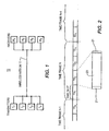
- FIG. 1 is a simplified system diagram of a basic TDM system.
- FIG. 2 illustrates the typical signal format used in TDD or TDM architecture.
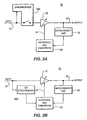
- FIGs. 3A, and 3B are simplified block diagrams an AGC system with a gain control signal synchronized to a designated time slot.
- FIG. 4 is a flow chart of the technique performed by the embodiments of FIG. 5.
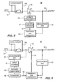
- FIG. 5 is a simplified block diagram of an AGC system with means for gain control level storage.
- FIG. 6 is a simplified block diagram of an AGC system with means for RF input signal storage.
- FIG. 7A is an alternative embodiment of FIG. 5 using a microprocessor to incorporate various system functions.
- FIG. 7B is an alternative embodiment of FIG. 7A using a microprocessor to additionally include the variable amplifier of the system.
- this shows a typical TDD/TDM system 10. It consists of several transmitters denoted as T1, T2, T3 and T4, and of several receivers, denoted as R1, R2, R3 and R4.
- the number of transmitters and receivers, four (4) and four (4) respectively (and hence the corresponding number of time slots), is chosen for illustrative purposes and as such, other possible embodiments may comprise a greater or lesser number oftime slots, transmitters and receivers.
- the transmitters T1-T4 and receivers R1-R4 communicate via a wireless medium 11. These communications are so timed such that receiver R1 processes signals from its associated transmitter T1, receiver R2 processes signals from its associated transmitter T2, and so on.
- FIG. 2 shows atypical time frame N, during which communications between the four associated pairs of transmitters T1-T4 and receivers R1-R4 of FIG. 1 take place.
- frame N is subdivided into four consecutive time slots, designated TS1, TS2, TS3 and TS4.
- TS1, TS2, TS3 and TS4 are consecutive time slots, designated TS1, TS2, TS3 and TS4.
- receiver R1 of FIG. 1 is intended to process signals from transmitter T1 in FIG. 1.
- time slot TS2 the same applies to receiver R2 and its associated transmitter T2, and so on for time slots TS3 and TS4.
- a time frame occurs again and again, each again subdivided into the four time slots shown for frame N. This is indicated in FIG.
- time slots to particular transmitters and receivers are made herein for explanatory purposes. However, it should be understood by those of skill in the art that time slots will be assigned dynamically as needed in accordance with prior art techniques.
- FIG. 2 Also shown in FIG. 2 is an expanded view of a time slot, using as an example time slot TS2 of frame N. This shows a central portion 20, within which data is transmitted and received, flanked by guard bands 21, during which there is no data transmission or reception. The present invention will operate either with or without guard bands 21.
- an AGC system 30 is used, for example, in receiver R1 of FIG. 1, responding to designated time slot TS1.
- the AGC system 30 comprises an input 31, an output 36, a synchronizer 38A, and a closed feedback loop comprising a variable amplifier 35, a measurement unit 32 and a reference and comparison unit 33.
- the input 31 provides the RF input signal which has been detected by the receiver R1.
- the RF input signal comprises a plurality of repeating time frames, each including a plurality of time slots TS1-TS4 as shown in FIG. 2.
- FIG. 2 shows four time slots TS1-TS4, those of skill in the art would clearly recognize that more or less time slots could be used as required by the particular application.
- the variable amplifier 35 receives the RF input signal from the input 31 and amplifies or attenuates the signal.
- the measurement unit 32 measures the output of the variable amplifier 35. This measurement is forwarded to the reference and comparison unit 33 which compares the output of the measurement unit 32 with a predetermined reference. As a result ofthis comparison, the reference and comparison unit 33 outputs an error control signal 34 to the variable amplifier 35 to increase or decrease the amount of amplification or attenuation as desired, to keep the variable amplifier output 36 within a predefined operating range as required by the downstream electronic components (not shown).
- the synchronizer 38A utilizes a switch to couple the input 31 to the AGC system 30 during time slot TS1 and to decouple the input 31 during all other time slots TS2 - TS4. The synchronized input ensures that the input 31 is timely coupled to the AGC system 30 during all occurrences of the applicable time slot, (in this example TS1).
- FIG. 3B shows an alternate embodiment wherein the synchronizer 38B comprises a sample and hold unit in which sampling of the input 31 is synchronized to the frequency of time slot TS1.
- a control signal from the synchronizer 38B selectively overrides the signal generated by the reference and comparison unit 33.
- the synchronizer 38B allows the gain control function provided by the measurement unit 32, the reference and comparison unit 33 and the amplifier 35 to operate normally.
- the signal from synchronizer 38B overrides the signal from the reference and comparison unit 33, in order to hold the gain of the variable amplifier 35 at the level that existed at the end of time slot TS1.
- sampling of the input 31 is synchronized to the occurrence of the desired time slot TS1.
- This allows the variable amplifier 35 to operate at a level much closer to the required level, particularly at the beginning of the next occurrence of time slot TS1, than would otherwise be possible had the AGC system 30 been allowed to vary across time slots TS1 - TS4 from one frame to the next.
- the result is an improved AGC system 30 with respect to setting the initial gain level during time slot TS1.
- an alternate embodiment of an AGC system 50 is shown.
- This embodiment of the AGC system 50 includes components similar to the prior embodiments, but further includes a control storage unit 51 and an estimate enhancement unit 53.
- the control storage unit 51 stores the control signal 34 output from the reference and comparison unit 33 for the designated time slot, such as TS1, over several time frames.
- the stored control signal 34 may comprise a single sample (such as at the end of time slot TS1), or may comprise an average of several samples of the control signal 34 over the entire duration of time slot TS1. This provides a more accurate estimate for time slot TS1 compared with a single sample of signal strength within time slot TS1.
- the synchronizer 38A, measurement unit 32, reference and comparison unit 33 and variable amplifier 35 all serve the same functions as the corresponding components shown in FIG. 3A.
- the estimate enhancement circuit 53 performs calculations of control signals stored in the control storage unit 51, including averaging a sequence of stored control signals derived during the time slot TS1 over several prior time frames. For example, a value of 0.2 for the control signal 34 would be the result of averaging performed on control signal 34 values of 0.1, 0.2, 0.2, 0.3, stored for time slot TS1 over four time frames. In another embodiment, the estimate enhancement circuit 53 may also perform a calculation to determine a rising or falling trend of a sequence of stored control signals 34.
- a value of 0.5 for the control signal 34 would be the result of a trending calculation performed on control signal 34 values 0.1, 0.2, 0.3, 0.4 of stored values for time slot TS1 over four time frames.
- the output of the estimate enhancement circuit 53 provides an improved estimate of the appropriate gain required for the next occurrence oftime slot TS1.
- estimate enhancement circuit 53, the control storage unit 51, the reference and comparison unit 33 and the measurement unit 32 are illustrated as separate components, they may be combined together as a single component as desired, such as a microprocessor (not shown).
- the variable amplifier 35 may also be incorporated into such a microprocessor to provide a single, unitary "smart AGC.”
- each respective receiver R1-R4 uses the process 400 to demodulate a signal intended for that particular receiver in accordance with the present invention to demodulate a signal intended for that particular receiver in accordance with the present invention to demodulate a signal intended for that particular receiver in accordance with the present invention to demodulate a signal intended for that particular receiver in accordance with the present invention to be shown in the flow diagram of FIG. 4.
- each receiver R1-R4 has been synchronized to the repeating time frames, and each receiver R1-R4 has also been preassigned to a particular time slot.
- multiple time slots for example two time slots such as TS1 and TS2, or TS1 and TS3, or even more than two time slots
- step 401 the initial AGC level of an initial time frame is set based on the closed loop feedback as in a typical AGC circuit without the benefit of a stored estimate.
- the transmitted signal 31 sent from T1 contained in time slot TS1 of frame N-1 is then measured in step 402.
- step 404 the signal is compared to a predetermined reference level, and an appropriate amplification or attenuation is calculated in step 406.
- An error control signal 34 for the variable amplifier 35 is then generated in step 408, based on the result of the calculation step 406, and is also stored in step 410 as an estimate for the next time frame.
- step 411 an improved estimate of the required control signal for the next time frame is determined in step 411, whereby an average or trend is calculated for a plurality of stored control signals stored over several earlier time frames.
- step 412 the "unenhanced" control signal stored at step 410 may be utilized for further processing.
- the AGC system 50 is then "deactivated”, “suspended”, or “switched out” in step 412, using synchronizer 38A until the next occurrence of TS1 in the subsequent frame is available for measurement, at which point the AGC system 50 is reactivated as shown in step 414.
- step 416 the stored control signal of step 410 (or alternatively, as calculated in step 411) is used to set the variable amplifier 35 at an estimated level of amplification.
- step 402 the process repeats starting at step 402, continuing through step 416 over the course of subsequent time frames, thereby providing a sequence of stored control signals.
- step 416 the process repeats starting at step 402, continuing through step 416 over the course of subsequent time frames, thereby providing a sequence of stored control signals.
- each subsequent reoccurrence of a time slot will update the control signal measurement, thereby providing a "rolling sequence" over a number of consecutive recurring time slots.
- the average or trend calculation of step 411 is performed on the "rolling sequence" of stored values. Utilizing this procedure, the AGC system 50 will expect the signal level of the next occurrence of TS1 to be within a certain range of the signal level in the prior occurrence of TS1. This permits much more stable and accurate operation of the AGC system 50.
- FIG. 6 shows another alternative embodiment of the present invention.
- the AGC system 60 analyzes the RF input signal 31 before being processed by the variable amplifier 35.
- the AGC system 60 also a closed loop type, comprises an input 31, a variable amplifier 35, preamplified a measurement unit 62, a reference and comparison unit 64, storage unit 61, a synchronizer 38A, an estimate enhancement unit 63 and an output 36.
- the synchronizer 38A ensures that the AGC system 60 acts on the RF input signal 31 only during the designated time slot for the subject receiver.
- the preamplified measurement unit 62 measures the receive signal strength of the RF input signal 31.
- the measured signal strength is then stored by input storage unit 61 for providing an estimate for subsequent receive signal strengths.
- a sequence of stored RF input signal strengths are retrieved by the estimate enhancement unit 63, which refines the estimate of the received signal strengths of several earlier occurrences of the designated time slot by analyzing the recorded sequence for increasing or decreasing trends, or by calculating an average of the sequence.
- This enhanced estimate is forwarded to a converter 65 which converts the refined RF input signal from the estimate enhancement unit 63 into a gain control signal 66 using a predefined target value for the output signal 36.
- the reference and comparison unit 64 utilizes the estimated gain control signal 66 only at the beginning of each desired time slot to produce the initial error control signal 34 at the beginning of the time slot.
- the measurement unit 32, reference and comparison unit 64 and the variable amplifier 35 operate as a typical AGC circuit to control the gain of the variable amplifier 35 and increase or decrease the amount of amplification or attenuation as required.
- the output 66 is ignored during this time.
- the preamplified measurement unit 62, the input storage 61, the estimate enhancement unit 63, the converter 66, the reference and comparison unit 64, the measurement unit 32 and the synchronizer 38A have been described herein as separate and discrete components, it should be noted that they perform functions that may be incorporated as part of a microprocessor 71 having an associated memory (not shown), as illustrated by the embodiment shown in FIG. 7A.
- the variable amplifier 35 may also be incorporated into the programmed microprocessor 71 to provide a single, unitary "smart AGC", as illustrated in FIG. 7B.
Description
- BACKGROUND
- Field of the Invention
- This invention relates generally to wireless communication systems. More particularly, the invention relates to a method for selectively measuring a received portion of a transmission signal to be applied to an automatic gain control (AGC) system of a receiver.
- Description of the Prior Art
- The time division duplex (TDD) and time division multiplex (TDM) systems of spread spectrum wireless communication operate on the principle of repeating frames of data transmission that are divided into successive time slots. In TDD and TDM wireless systems, there is often a significant and sudden variation in received signal strength between one time slot and the next. This is caused by the fact that different transmitters, with possibly different transmit powers, and possibly vastly different path losses to the associated receiver, operate in consecutive time slots. Furthermore there is typically a so-called "guard" period inserted between time slots, during which no unit in the network is allowed to transmit. This causes another significant and sudden variation in signal strength as the allowed transmission period of one time slot ends, followed by the guard period in which no unit transmits, and then followed again by another transmission in the following time slot.
- These sudden and often dramatic variations in received signal strength wreak havoc with traditional automatic gain control (AGC) systems. Such systems are typically employed to adjust the receiver gain so that widely varying signal strengths received at the antenna are reduced to more modest variations in signal strength at the A/D converter, the detector or other devices within the receiver. Without such a reduction in the range of signal strengths, the operation of the A/D converter, the detector or other devices within the receiver can be severely impaired or rendered inoperable.
- Conventionally, AGC systems employ closed loop control systems which operate on the continuously received signal. The response speed of such AGC systems must often be limited so as to prevent instability and/or prevent the AGC from eliminating the rapid amplitude variations that are an inherent and essential part of many modulation schemes. Therefore, there are contradictory requirements which, on the one hand, call for a slow AGC response (so as to stabilize the system and not eliminate the essential amplitude variations), and on the other hand, call for a rapid AGC response in order to adjust to the rapidly varying received signal strength. It should also be noted that the information at the beginning of a received time slot, before the AGC has time to properly respond, may be lost or useless. In some systems it has been considered necessary to insert a period at the beginning of a time slot transmission in which no information is sent, even though the transmitter is active. Although this gives the receiver's AGC time to respond, this technique wastes precious bandwidth.
Documents WO-A-9117606 and US-A-5638375 describe prior art AGC systems. - SUMMARY
- The present invention is a system or technique in which the automatic gain control of a received TDD or TDM signal for a given receiver is performed only during those specific time slots in which that particular receiver processes transmissions from its associated transmitter. One or more samples of gain control signals are stored until the next recurrence of the specific time slot in a subsequent frame. They are then treated as an estimate of the initial gain level required at the beginning of that subsequent time slot.
- The receiver AGC operates at the start of that subsequent time slot under the control of this estimate, derived from measured signal strength made during the same time slot in a preceding frame. In this way, the AGC operation during any given time slot becomes unaffected by excessive signal strength variations from one time slot to the next within a single time frame. The initial setting of the gain control level at the beginning of a specific time slot is especially improved as the AGC operation of the receiver resumes more smoothly over successive time frames.
- Further improvement can be obtained by deriving the estimate of initial gain level, not just from a single time slot in a prior frame, but rather from the average of several such prior time slots, or by determining trends in the prior gain control signals.
- BRIEF DESCRIPTION OF THE DRAWINGS
- FIG. 1 is a simplified system diagram of a basic TDM system.
- FIG. 2 illustrates the typical signal format used in TDD or TDM architecture.
- FIGs. 3A, and 3B are simplified block diagrams an AGC system with a gain control signal synchronized to a designated time slot.
- FIG. 4 is a flow chart of the technique performed by the embodiments of FIG. 5.
- FIG. 5 is a simplified block diagram of an AGC system with means for gain control level storage.
- FIG. 6 is a simplified block diagram of an AGC system with means for RF input signal storage.
- FIG. 7A is an alternative embodiment of FIG. 5 using a microprocessor to incorporate various system functions.
- FIG. 7B is an alternative embodiment of FIG. 7A using a microprocessor to additionally include the variable amplifier of the system.
- DETAILED DESCRIPTION
- Referring to FIG. 1, this shows a typical TDD/
TDM system 10. It consists of several transmitters denoted as T1, T2, T3 and T4, and of several receivers, denoted as R1, R2, R3 and R4. The number of transmitters and receivers, four (4) and four (4) respectively (and hence the corresponding number of time slots), is chosen for illustrative purposes and as such, other possible embodiments may comprise a greater or lesser number oftime slots, transmitters and receivers. The transmitters T1-T4 and receivers R1-R4 communicate via awireless medium 11. These communications are so timed such that receiver R1 processes signals from its associated transmitter T1, receiver R2 processes signals from its associated transmitter T2, and so on. - The timing architecture of these communications between associated transmitters and receivers is illustrated in FIG. 2, which shows atypical time frame N, during which communications between the four associated pairs of transmitters T1-T4 and receivers R1-R4 of FIG. 1 take place. To that end, frame N is subdivided into four consecutive time slots, designated TS1, TS2, TS3 and TS4. During time slot TS1, receiver R1 of FIG. 1 is intended to process signals from transmitter T1 in FIG. 1. During time slot TS2, the same applies to receiver R2 and its associated transmitter T2, and so on for time slots TS3 and TS4. A time frame occurs again and again, each again subdivided into the four time slots shown for frame N. This is indicated in FIG. 2 by showing the last time slot TS4 of the frame N-1 which precedes frame N and the first time slot TS1 of the frame N+1, which follows frame N. The designation of time slots to particular transmitters and receivers is made herein for explanatory purposes. However, it should be understood by those of skill in the art that time slots will be assigned dynamically as needed in accordance with prior art techniques.
- Also shown in FIG. 2 is an expanded view of a time slot, using as an example time slot TS2 of frame N. This shows a
central portion 20, within which data is transmitted and received, flanked byguard bands 21, during which there is no data transmission or reception. The present invention will operate either with or withoutguard bands 21. - Referring now to FIG. 3A, an
AGC system 30 is used, for example, in receiver R1 of FIG. 1, responding to designated time slot TS1. TheAGC system 30 comprises aninput 31, anoutput 36, asynchronizer 38A, and a closed feedback loop comprising avariable amplifier 35, ameasurement unit 32 and a reference andcomparison unit 33. Theinput 31 provides the RF input signal which has been detected by the receiver R1. The RF input signal comprises a plurality of repeating time frames, each including a plurality of time slots TS1-TS4 as shown in FIG. 2. Although FIG. 2 shows four time slots TS1-TS4, those of skill in the art would clearly recognize that more or less time slots could be used as required by the particular application. - The
variable amplifier 35 receives the RF input signal from theinput 31 and amplifies or attenuates the signal. Themeasurement unit 32 measures the output of thevariable amplifier 35. This measurement is forwarded to the reference andcomparison unit 33 which compares the output of themeasurement unit 32 with a predetermined reference. As a result ofthis comparison, the reference andcomparison unit 33 outputs anerror control signal 34 to thevariable amplifier 35 to increase or decrease the amount of amplification or attenuation as desired, to keep thevariable amplifier output 36 within a predefined operating range as required by the downstream electronic components (not shown). Thesynchronizer 38A utilizes a switch to couple theinput 31 to theAGC system 30 during time slot TS1 and to decouple theinput 31 during all other time slots TS2 - TS4. The synchronized input ensures that theinput 31 is timely coupled to theAGC system 30 during all occurrences of the applicable time slot, (in this example TS1). - FIG. 3B shows an alternate embodiment wherein the
synchronizer 38B comprises a sample and hold unit in which sampling of theinput 31 is synchronized to the frequency of time slot TS1. A control signal from thesynchronizer 38B selectively overrides the signal generated by the reference andcomparison unit 33. During the applicable time slot (i.e. TS1), thesynchronizer 38B allows the gain control function provided by themeasurement unit 32, the reference andcomparison unit 33 and theamplifier 35 to operate normally. During time slots other than TS1, the signal fromsynchronizer 38B overrides the signal from the reference andcomparison unit 33, in order to hold the gain of thevariable amplifier 35 at the level that existed at the end of time slot TS1. - By having
synchronizer AGC system 30, sampling of theinput 31 is synchronized to the occurrence of the desired time slot TS1. This allows thevariable amplifier 35 to operate at a level much closer to the required level, particularly at the beginning of the next occurrence of time slot TS1, than would otherwise be possible had theAGC system 30 been allowed to vary across time slots TS1 - TS4 from one frame to the next. The result is animproved AGC system 30 with respect to setting the initial gain level during time slot TS1. - Referring to FIG. 5, an alternate embodiment of an
AGC system 50 is shown. This embodiment of theAGC system 50 includes components similar to the prior embodiments, but further includes acontrol storage unit 51 and anestimate enhancement unit 53. Thecontrol storage unit 51 stores thecontrol signal 34 output from the reference andcomparison unit 33 for the designated time slot, such as TS1, over several time frames. The storedcontrol signal 34 may comprise a single sample (such as at the end of time slot TS1), or may comprise an average of several samples of thecontrol signal 34 over the entire duration of time slot TS1. This provides a more accurate estimate for time slot TS1 compared with a single sample of signal strength within time slot TS1. Thesynchronizer 38A,measurement unit 32, reference andcomparison unit 33 andvariable amplifier 35 all serve the same functions as the corresponding components shown in FIG. 3A. - In a first embodiment of
AGC system 50, theestimate enhancement circuit 53 performs calculations of control signals stored in thecontrol storage unit 51, including averaging a sequence of stored control signals derived during the time slot TS1 over several prior time frames. For example, a value of 0.2 for thecontrol signal 34 would be the result of averaging performed oncontrol signal 34 values of 0.1, 0.2, 0.2, 0.3, stored for time slot TS1 over four time frames. In another embodiment, theestimate enhancement circuit 53 may also perform a calculation to determine a rising or falling trend of a sequence of stored control signals 34. For example, a value of 0.5 for thecontrol signal 34 would be the result of a trending calculation performed oncontrol signal 34 values 0.1, 0.2, 0.3, 0.4 of stored values for time slot TS1 over four time frames. Thus, the output of theestimate enhancement circuit 53 provides an improved estimate of the appropriate gain required for the next occurrence oftime slot TS1. There are many statistical trending algorithms available in the prior art, and any of these algorithms may be utilized by the present invention. A detailed discussion of such algorithms is outside the scope of the present invention. It should be noted that although theestimate enhancement circuit 53, thecontrol storage unit 51, the reference andcomparison unit 33 and themeasurement unit 32 are illustrated as separate components, they may be combined together as a single component as desired, such as a microprocessor (not shown). Thevariable amplifier 35 may also be incorporated into such a microprocessor to provide a single, unitary "smart AGC." - The
process 400 used by each respective receiver R1-R4 to demodulate a signal intended for that particular receiver in accordance with the present invention is shown in the flow diagram of FIG. 4. For thisprocess 400, it is assumed that each receiver R1-R4 has been synchronized to the repeating time frames, and each receiver R1-R4 has also been preassigned to a particular time slot. The prior description notwithstanding, it also should be understood that although a single time slot for each receiver R1-R4 is used as an example for simplicity of explanation, multiple time slots (for example two time slots such as TS1 and TS2, or TS1 and TS3, or even more than two time slots), may be assigned to a particular receiver, (for example R1), for higher data rate communications. The foregoing discussion also assumes that the received RF signal has been downconverted and despread. However, it should be recognized that the individual signals in each time slot may be spread using different spreading codes and, therefore, only the code associated with the desired time slot(s) is despread. - Using the
AGC system 50 of FIG. 5 as an example, instep 401, the initial AGC level of an initial time frame is set based on the closed loop feedback as in a typical AGC circuit without the benefit of a stored estimate. The transmittedsignal 31 sent from T1 contained in time slot TS1 of frame N-1 is then measured instep 402. Next, instep 404, the signal is compared to a predetermined reference level, and an appropriate amplification or attenuation is calculated instep 406. Anerror control signal 34 for thevariable amplifier 35 is then generated instep 408, based on the result of thecalculation step 406, and is also stored instep 410 as an estimate for the next time frame. If desired, an improved estimate of the required control signal for the next time frame is determined instep 411, whereby an average or trend is calculated for a plurality of stored control signals stored over several earlier time frames. However, this is an optional feature and the "unenhanced" control signal stored atstep 410 may be utilized for further processing. TheAGC system 50 is then "deactivated", "suspended", or "switched out" instep 412, usingsynchronizer 38A until the next occurrence of TS1 in the subsequent frame is available for measurement, at which point theAGC system 50 is reactivated as shown instep 414. Finally, instep 416, the stored control signal of step 410 (or alternatively, as calculated in step 411) is used to set thevariable amplifier 35 at an estimated level of amplification. - As shown in FIG. 4, the process repeats starting at
step 402, continuing throughstep 416 over the course of subsequent time frames, thereby providing a sequence of stored control signals. If an average or trend is calculated, each subsequent reoccurrence of a time slot will update the control signal measurement, thereby providing a "rolling sequence" over a number of consecutive recurring time slots. The average or trend calculation ofstep 411 is performed on the "rolling sequence" of stored values. Utilizing this procedure, theAGC system 50 will expect the signal level of the next occurrence of TS1 to be within a certain range of the signal level in the prior occurrence of TS1. This permits much more stable and accurate operation of theAGC system 50. - FIG. 6 shows another alternative embodiment of the present invention. Rather than using feedback on the
output 36 of thevariable amplifier 35 to determine the control signal forvariable amplifier 35, theAGC system 60 analyzes theRF input signal 31 before being processed by thevariable amplifier 35. TheAGC system 60, also a closed loop type, comprises aninput 31, avariable amplifier 35, preamplified ameasurement unit 62, a reference andcomparison unit 64,storage unit 61, asynchronizer 38A, anestimate enhancement unit 63 and anoutput 36. - The
synchronizer 38A ensures that theAGC system 60 acts on theRF input signal 31 only during the designated time slot for the subject receiver. Thepreamplified measurement unit 62 measures the receive signal strength of theRF input signal 31. The measured signal strength is then stored byinput storage unit 61 for providing an estimate for subsequent receive signal strengths. Over the course of several time frames, a sequence of stored RF input signal strengths are retrieved by theestimate enhancement unit 63, which refines the estimate of the received signal strengths of several earlier occurrences of the designated time slot by analyzing the recorded sequence for increasing or decreasing trends, or by calculating an average of the sequence. This enhanced estimate is forwarded to aconverter 65 which converts the refined RF input signal from theestimate enhancement unit 63 into again control signal 66 using a predefined target value for theoutput signal 36. The reference andcomparison unit 64 utilizes the estimatedgain control signal 66 only at the beginning of each desired time slot to produce the initialerror control signal 34 at the beginning of the time slot. - Subsequent to the beginning of the time slot, the
measurement unit 32, reference andcomparison unit 64 and thevariable amplifier 35 operate as a typical AGC circuit to control the gain of thevariable amplifier 35 and increase or decrease the amount of amplification or attenuation as required. Theoutput 66 is ignored during this time. - Although the
preamplified measurement unit 62, theinput storage 61, theestimate enhancement unit 63, theconverter 66, the reference andcomparison unit 64, themeasurement unit 32 and thesynchronizer 38A have been described herein as separate and discrete components, it should be noted that they perform functions that may be incorporated as part of amicroprocessor 71 having an associated memory (not shown), as illustrated by the embodiment shown in FIG. 7A. Thevariable amplifier 35 may also be incorporated into the programmedmicroprocessor 71 to provide a single, unitary "smart AGC", as illustrated in FIG. 7B. - While the present invention has been described in terms of the preferred embodiments, other variations which are within the scope of the invention as outlined in the claims below will be apparent to those skilled in the art.
Claims (8)
- A time division duplex (TDD) receiver for communication with one of a plurality of transmitters (T1-T4), utilizing repetitive time frames, each time frame subdivided into a plurality of time slots (TS1-TS4), at least a first time slot allocated to a communication between a first transmitter and the receiver, comprising:means for automatic gain control (AGC), comprising:means for measuring (32), at the receiver, the received signal strength only during said at least first time slot in each of a plurality of successive time frames;means for utilizing (33, 64) said measured signal strengths to set an initial gain level of the receiver at said at least first time slot in a subsequent time frame;means for storing (51, 61) a plurality of said initial gain level settings of successive timeframes;means for determining the trend (53, 63) of the stored initial gain levels; andmeans for utilizing (53, 64, 65, 66) said trend to control the gain of said receiver during the corresponding time slot in a subsequent time frame.
- The receiver of claim 1, wherein said subsequent time frame is the next consecutive time frame.
- The receiver of claim 1, wherein said AGC means further includes:means for storing (51, 61) a plurality of gain level settings of successive time frames; andmeans for averaging (53,63) said gain level settings to determine said initial gain control level of said receiver during the corresponding time slot in a subsequent time frame.
- The receiver of claim 1, wherein said AGC means further includes:means for storing (51, 61) a plurality of said initial gain levels settings of successive time frames;means for determining the average (53, 63) of the stored initial gain levels; andmeans for utilizing (53, 64, 65, 66) said average to control the gain of said receiver during the corresponding time slot in a subsequent time frame.
- The receiver of claim 1, wherein said AGC means further includes:means for storing (51, 61) a plurality of said measured signal strengths;means for determining the trend (53, 63) of the stored signals strengths; andmeans for utilizing (58, 64, 65, 66) said trend to control the gain of said receiver during the corresponding time slot in a subsequent time frame.
- The receiver of claim 5 wherein a microprocessor (71) is used for said determining means and said utilizing means.
- The receiver of claim 1, wherein said AGC means further includes:means for storing(51, 61) a plurality of said measured signal strengths;means for determining the average (53,63) of the stored signal strengths; andmeans for utilizing (53, 64, 65, 66) said average to control the gain of said receivers during the corresponding time slot in a subsequent time frame.
- The receiver of claim 7 wherein a microprocessor (71) is used for said determining means and said utilizing means.
Applications Claiming Priority (5)
| Application Number | Priority Date | Filing Date | Title |
|---|---|---|---|
| US24165100P | 2000-10-19 | 2000-10-19 | |
| US241651P | 2000-10-19 | ||
| US09/872,038 US7085255B2 (en) | 2000-10-19 | 2001-06-01 | Selectively activated AGC signal measurement unit |
| US872038 | 2001-06-01 | ||
| EP01981554A EP1327313B1 (en) | 2000-10-19 | 2001-10-12 | Selectively activated agc signal measurement unit |
Related Parent Applications (1)
| Application Number | Title | Priority Date | Filing Date |
|---|---|---|---|
| EP01981554A Division EP1327313B1 (en) | 2000-10-19 | 2001-10-12 | Selectively activated agc signal measurement unit |
Publications (2)
| Publication Number | Publication Date |
|---|---|
| EP1458117A1 EP1458117A1 (en) | 2004-09-15 |
| EP1458117B1 true EP1458117B1 (en) | 2006-07-05 |
Family
ID=32776531
Family Applications (1)
| Application Number | Title | Priority Date | Filing Date |
|---|---|---|---|
| EP04012221A Expired - Lifetime EP1458117B1 (en) | 2000-10-19 | 2001-10-12 | TDD receiver with selectively activated agc signal measurement unit |
Country Status (2)
| Country | Link |
|---|---|
| EP (1) | EP1458117B1 (en) |
| DK (1) | DK1458117T3 (en) |
Family Cites Families (3)
| Publication number | Priority date | Publication date | Assignee | Title |
|---|---|---|---|---|
| US5119508A (en) * | 1988-11-18 | 1992-06-02 | Motorola, Inc. | Predictive AGC in TDM systems |
| US5638375A (en) * | 1988-11-30 | 1997-06-10 | Motorola, Inc. | AGC isolation of information in TDMA systems |
| WO1991017606A1 (en) * | 1990-04-27 | 1991-11-14 | Motorola, Inc. | Digital automatic gain control |
-
2001
- 2001-10-12 DK DK04012221T patent/DK1458117T3/en active
- 2001-10-12 EP EP04012221A patent/EP1458117B1/en not_active Expired - Lifetime
Also Published As
| Publication number | Publication date |
|---|---|
| EP1458117A1 (en) | 2004-09-15 |
| DK1458117T3 (en) | 2006-10-30 |
Similar Documents
| Publication | Publication Date | Title |
|---|---|---|
| EP1327313B1 (en) | Selectively activated agc signal measurement unit | |
| EP0468507B1 (en) | Automatic power control apparatus | |
| EP0630106B1 (en) | Automatic gain control apparatus | |
| EP1061643B1 (en) | Receiver and gain control method of the same | |
| EP0917304B1 (en) | Transmission power control method and communication device | |
| EP1458117B1 (en) | TDD receiver with selectively activated agc signal measurement unit | |
| HUT74332A (en) | Receiver path selection in time devision multiple access receivers | |
| US5630219A (en) | Reception electric field level detection circuit | |
| KR19990061211A (en) | Apparatus and method capable of automatic gain adjustment and automatic level adjustment | |
| US7197289B2 (en) | Automatic gain control for a wireless transmit/receive unit in a time slotted data transmissions | |
| WO1999023777A1 (en) | Transmitter and receiver for multi-rated delay multiplexing direct spread spectrum communication system, and multi-rated delay multiplexing direct spread spectrum communication system | |
| EP0597448A1 (en) | The apparatus for adjusting the efficiency of electric power amplification | |
| JP3976741B2 (en) | Transmission signal generating apparatus, radio base station, automatic gain control method, and radio signal transmission method | |
| US5933433A (en) | Method and system for reception timing control | |
| JP3873052B2 (en) | Wireless communication system and wireless communication apparatus | |
| JP3885625B2 (en) | Automatic reception gain control method and apparatus | |
| JP4108647B2 (en) | Mobile communication system, transmitter, and automatic gain control method used therefor | |
| GB2281157A (en) | Gain control using sampling suitable for TDMA systems | |
| KR20070008015A (en) | Syncronizing method in a tdd type wireless repeater | |
| JP4050212B2 (en) | Signal receiving device | |
| US20020159504A1 (en) | Transmitting apparatus and gain compensating method | |
| JPH05102939A (en) | Receiver for time-division multiple digital radio communication system | |
| JP2001060981A (en) | Linear demodulating method and radio equipment for executing linear demodulation | |
| KR20060046676A (en) | Apparatus and method for detecting preamble and rf repeating system using that | |
| JPH09186539A (en) | Automatic gain control amplifier |
Legal Events
| Date | Code | Title | Description |
|---|---|---|---|
| PUAI | Public reference made under article 153(3) epc to a published international application that has entered the european phase |
Free format text: ORIGINAL CODE: 0009012 |
|
| AC | Divisional application: reference to earlier application |
Ref document number: 1327313 Country of ref document: EP Kind code of ref document: P |
|
| AK | Designated contracting states |
Kind code of ref document: A1 Designated state(s): AT BE CH CY DE DK ES FI FR GB GR IE IT LI LU MC NL PT SE TR |
|
| 17P | Request for examination filed |
Effective date: 20050218 |
|
| AKX | Designation fees paid |
Designated state(s): AT BE CH CY DE DK ES FI FR GB GR IE IT LI LU MC NL PT SE TR |
|
| GRAP | Despatch of communication of intention to grant a patent |
Free format text: ORIGINAL CODE: EPIDOSNIGR1 |
|
| GRAS | Grant fee paid |
Free format text: ORIGINAL CODE: EPIDOSNIGR3 |
|
| GRAA | (expected) grant |
Free format text: ORIGINAL CODE: 0009210 |
|
| RAP1 | Party data changed (applicant data changed or rights of an application transferred) |
Owner name: INTERDIGITAL TECHNOLOGY CORPORATION |
|
| AC | Divisional application: reference to earlier application |
Ref document number: 1327313 Country of ref document: EP Kind code of ref document: P |
|
| AK | Designated contracting states |
Kind code of ref document: B1 Designated state(s): AT BE CH CY DE DK ES FI FR GB GR IE IT LI LU MC NL PT SE TR |
|
| PG25 | Lapsed in a contracting state [announced via postgrant information from national office to epo] |
Ref country code: IT Free format text: LAPSE BECAUSE OF FAILURE TO SUBMIT A TRANSLATION OF THE DESCRIPTION OR TO PAY THE FEE WITHIN THE PRESCRIBED TIME-LIMIT;WARNING: LAPSES OF ITALIAN PATENTS WITH EFFECTIVE DATE BEFORE 2007 MAY HAVE OCCURRED AT ANY TIME BEFORE 2007. THE CORRECT EFFECTIVE DATE MAY BE DIFFERENT FROM THE ONE RECORDED. Effective date: 20060705 Ref country code: AT Free format text: LAPSE BECAUSE OF FAILURE TO SUBMIT A TRANSLATION OF THE DESCRIPTION OR TO PAY THE FEE WITHIN THE PRESCRIBED TIME-LIMIT Effective date: 20060705 Ref country code: CH Free format text: LAPSE BECAUSE OF FAILURE TO SUBMIT A TRANSLATION OF THE DESCRIPTION OR TO PAY THE FEE WITHIN THE PRESCRIBED TIME-LIMIT Effective date: 20060705 Ref country code: BE Free format text: LAPSE BECAUSE OF FAILURE TO SUBMIT A TRANSLATION OF THE DESCRIPTION OR TO PAY THE FEE WITHIN THE PRESCRIBED TIME-LIMIT Effective date: 20060705 Ref country code: NL Free format text: LAPSE BECAUSE OF FAILURE TO SUBMIT A TRANSLATION OF THE DESCRIPTION OR TO PAY THE FEE WITHIN THE PRESCRIBED TIME-LIMIT Effective date: 20060705 Ref country code: LI Free format text: LAPSE BECAUSE OF FAILURE TO SUBMIT A TRANSLATION OF THE DESCRIPTION OR TO PAY THE FEE WITHIN THE PRESCRIBED TIME-LIMIT Effective date: 20060705 |
|
| REG | Reference to a national code |
Ref country code: GB Ref legal event code: FG4D |
|
| REG | Reference to a national code |
Ref country code: CH Ref legal event code: EP |
|
| REG | Reference to a national code |
Ref country code: IE Ref legal event code: FG4D |
|
| REF | Corresponds to: |
Ref document number: 60121374 Country of ref document: DE Date of ref document: 20060817 Kind code of ref document: P |
|
| REG | Reference to a national code |
Ref country code: SE Ref legal event code: TRGR |
|
| PG25 | Lapsed in a contracting state [announced via postgrant information from national office to epo] |
Ref country code: IE Free format text: LAPSE BECAUSE OF NON-PAYMENT OF DUE FEES Effective date: 20061012 |
|
| REG | Reference to a national code |
Ref country code: DK Ref legal event code: T3 |
|
| PG25 | Lapsed in a contracting state [announced via postgrant information from national office to epo] |
Ref country code: MC Free format text: LAPSE BECAUSE OF NON-PAYMENT OF DUE FEES Effective date: 20061031 |
|
| ET | Fr: translation filed | ||
| NLV1 | Nl: lapsed or annulled due to failure to fulfill the requirements of art. 29p and 29m of the patents act | ||
| REG | Reference to a national code |
Ref country code: ES Ref legal event code: FG2A Ref document number: 2263089 Country of ref document: ES Kind code of ref document: T3 |
|
| PG25 | Lapsed in a contracting state [announced via postgrant information from national office to epo] |
Ref country code: PT Free format text: LAPSE BECAUSE OF FAILURE TO SUBMIT A TRANSLATION OF THE DESCRIPTION OR TO PAY THE FEE WITHIN THE PRESCRIBED TIME-LIMIT Effective date: 20061205 |
|
| PLBE | No opposition filed within time limit |
Free format text: ORIGINAL CODE: 0009261 |
|
| STAA | Information on the status of an ep patent application or granted ep patent |
Free format text: STATUS: NO OPPOSITION FILED WITHIN TIME LIMIT |
|
| 26N | No opposition filed |
Effective date: 20070410 |
|
| PGFP | Annual fee paid to national office [announced via postgrant information from national office to epo] |
Ref country code: DK Payment date: 20071015 Year of fee payment: 7 |
|
| PG25 | Lapsed in a contracting state [announced via postgrant information from national office to epo] |
Ref country code: GR Free format text: LAPSE BECAUSE OF FAILURE TO SUBMIT A TRANSLATION OF THE DESCRIPTION OR TO PAY THE FEE WITHIN THE PRESCRIBED TIME-LIMIT Effective date: 20061006 |
|
| PG25 | Lapsed in a contracting state [announced via postgrant information from national office to epo] |
Ref country code: TR Free format text: LAPSE BECAUSE OF FAILURE TO SUBMIT A TRANSLATION OF THE DESCRIPTION OR TO PAY THE FEE WITHIN THE PRESCRIBED TIME-LIMIT Effective date: 20060705 Ref country code: LU Free format text: LAPSE BECAUSE OF NON-PAYMENT OF DUE FEES Effective date: 20061012 |
|
| PG25 | Lapsed in a contracting state [announced via postgrant information from national office to epo] |
Ref country code: CY Free format text: LAPSE BECAUSE OF FAILURE TO SUBMIT A TRANSLATION OF THE DESCRIPTION OR TO PAY THE FEE WITHIN THE PRESCRIBED TIME-LIMIT Effective date: 20060705 |
|
| REG | Reference to a national code |
Ref country code: DK Ref legal event code: EBP |
|
| PG25 | Lapsed in a contracting state [announced via postgrant information from national office to epo] |
Ref country code: IT Free format text: LAPSE BECAUSE OF NON-PAYMENT OF DUE FEES Effective date: 20071012 |
|
| PG25 | Lapsed in a contracting state [announced via postgrant information from national office to epo] |
Ref country code: DK Free format text: LAPSE BECAUSE OF NON-PAYMENT OF DUE FEES Effective date: 20081031 |
|
| PGRI | Patent reinstated in contracting state [announced from national office to epo] |
Ref country code: IT Effective date: 20110616 |
|
| PGFP | Annual fee paid to national office [announced via postgrant information from national office to epo] |
Ref country code: ES Payment date: 20130911 Year of fee payment: 13 |
|
| PGFP | Annual fee paid to national office [announced via postgrant information from national office to epo] |
Ref country code: DE Payment date: 20131009 Year of fee payment: 13 Ref country code: FR Payment date: 20131009 Year of fee payment: 13 Ref country code: SE Payment date: 20131011 Year of fee payment: 13 Ref country code: GB Payment date: 20131009 Year of fee payment: 13 |
|
| PGFP | Annual fee paid to national office [announced via postgrant information from national office to epo] |
Ref country code: IT Payment date: 20131015 Year of fee payment: 13 Ref country code: FI Payment date: 20131010 Year of fee payment: 13 |
|
| REG | Reference to a national code |
Ref country code: DE Ref legal event code: R119 Ref document number: 60121374 Country of ref document: DE |
|
| REG | Reference to a national code |
Ref country code: SE Ref legal event code: EUG |
|
| GBPC | Gb: european patent ceased through non-payment of renewal fee |
Effective date: 20141012 |
|
| PG25 | Lapsed in a contracting state [announced via postgrant information from national office to epo] |
Ref country code: FI Free format text: LAPSE BECAUSE OF NON-PAYMENT OF DUE FEES Effective date: 20141012 Ref country code: GB Free format text: LAPSE BECAUSE OF NON-PAYMENT OF DUE FEES Effective date: 20141012 Ref country code: SE Free format text: LAPSE BECAUSE OF NON-PAYMENT OF DUE FEES Effective date: 20141013 Ref country code: DE Free format text: LAPSE BECAUSE OF NON-PAYMENT OF DUE FEES Effective date: 20150501 |
|
| REG | Reference to a national code |
Ref country code: FR Ref legal event code: ST Effective date: 20150630 |
|
| PG25 | Lapsed in a contracting state [announced via postgrant information from national office to epo] |
Ref country code: FR Free format text: LAPSE BECAUSE OF NON-PAYMENT OF DUE FEES Effective date: 20141031 Ref country code: IT Free format text: LAPSE BECAUSE OF NON-PAYMENT OF DUE FEES Effective date: 20141012 |
|
| REG | Reference to a national code |
Ref country code: ES Ref legal event code: FD2A Effective date: 20151127 |
|
| PG25 | Lapsed in a contracting state [announced via postgrant information from national office to epo] |
Ref country code: ES Free format text: LAPSE BECAUSE OF NON-PAYMENT OF DUE FEES Effective date: 20141013 |