EP1457774A1 - Separation analyser - Google Patents
Separation analyser Download PDFInfo
- Publication number
- EP1457774A1 EP1457774A1 EP04004088A EP04004088A EP1457774A1 EP 1457774 A1 EP1457774 A1 EP 1457774A1 EP 04004088 A EP04004088 A EP 04004088A EP 04004088 A EP04004088 A EP 04004088A EP 1457774 A1 EP1457774 A1 EP 1457774A1
- Authority
- EP
- European Patent Office
- Prior art keywords
- pump
- solution
- flow
- passage
- separation
- Prior art date
- Legal status (The legal status is an assumption and is not a legal conclusion. Google has not performed a legal analysis and makes no representation as to the accuracy of the status listed.)
- Granted
Links
Images




Classifications
-
- G—PHYSICS
- G01—MEASURING; TESTING
- G01N—INVESTIGATING OR ANALYSING MATERIALS BY DETERMINING THEIR CHEMICAL OR PHYSICAL PROPERTIES
- G01N35/00—Automatic analysis not limited to methods or materials provided for in any single one of groups G01N1/00 - G01N33/00; Handling materials therefor
- G01N35/10—Devices for transferring samples or any liquids to, in, or from, the analysis apparatus, e.g. suction devices, injection devices
- G01N35/1095—Devices for transferring samples or any liquids to, in, or from, the analysis apparatus, e.g. suction devices, injection devices for supplying the samples to flow-through analysers
- G01N35/1097—Devices for transferring samples or any liquids to, in, or from, the analysis apparatus, e.g. suction devices, injection devices for supplying the samples to flow-through analysers characterised by the valves
-
- G—PHYSICS
- G01—MEASURING; TESTING
- G01N—INVESTIGATING OR ANALYSING MATERIALS BY DETERMINING THEIR CHEMICAL OR PHYSICAL PROPERTIES
- G01N30/00—Investigating or analysing materials by separation into components using adsorption, absorption or similar phenomena or using ion-exchange, e.g. chromatography or field flow fractionation
- G01N30/02—Column chromatography
- G01N30/04—Preparation or injection of sample to be analysed
- G01N30/16—Injection
- G01N30/20—Injection using a sampling valve
-
- G—PHYSICS
- G01—MEASURING; TESTING
- G01N—INVESTIGATING OR ANALYSING MATERIALS BY DETERMINING THEIR CHEMICAL OR PHYSICAL PROPERTIES
- G01N1/00—Sampling; Preparing specimens for investigation
- G01N1/28—Preparing specimens for investigation including physical details of (bio-)chemical methods covered elsewhere, e.g. G01N33/50, C12Q
- G01N1/38—Diluting, dispersing or mixing samples
-
- G—PHYSICS
- G01—MEASURING; TESTING
- G01N—INVESTIGATING OR ANALYSING MATERIALS BY DETERMINING THEIR CHEMICAL OR PHYSICAL PROPERTIES
- G01N30/00—Investigating or analysing materials by separation into components using adsorption, absorption or similar phenomena or using ion-exchange, e.g. chromatography or field flow fractionation
- G01N30/02—Column chromatography
- G01N2030/022—Column chromatography characterised by the kind of separation mechanism
- G01N2030/027—Liquid chromatography
-
- G—PHYSICS
- G01—MEASURING; TESTING
- G01N—INVESTIGATING OR ANALYSING MATERIALS BY DETERMINING THEIR CHEMICAL OR PHYSICAL PROPERTIES
- G01N30/00—Investigating or analysing materials by separation into components using adsorption, absorption or similar phenomena or using ion-exchange, e.g. chromatography or field flow fractionation
- G01N30/02—Column chromatography
- G01N30/26—Conditioning of the fluid carrier; Flow patterns
- G01N30/28—Control of physical parameters of the fluid carrier
- G01N30/34—Control of physical parameters of the fluid carrier of fluid composition, e.g. gradient
-
- Y—GENERAL TAGGING OF NEW TECHNOLOGICAL DEVELOPMENTS; GENERAL TAGGING OF CROSS-SECTIONAL TECHNOLOGIES SPANNING OVER SEVERAL SECTIONS OF THE IPC; TECHNICAL SUBJECTS COVERED BY FORMER USPC CROSS-REFERENCE ART COLLECTIONS [XRACs] AND DIGESTS
- Y10—TECHNICAL SUBJECTS COVERED BY FORMER USPC
- Y10T—TECHNICAL SUBJECTS COVERED BY FORMER US CLASSIFICATION
- Y10T436/00—Chemistry: analytical and immunological testing
- Y10T436/25—Chemistry: analytical and immunological testing including sample preparation
- Y10T436/2575—Volumetric liquid transfer
Definitions
- the present invention relates to a separation analyzer, and more particularly to a separation analyzer for realizing gradient separation analysis at a rate of a nano-flow level (nL/min.).
- gradient is used to mean “preparation of divided solutions having different mixing ratios each other, the solutions being prepared by mixing plural kinds of solutions”.
- the solutions for analysis have gradient concentrations as a whole.
- An object of the present invention is to solve the above-mentioned problems and to conduct separation analysis according to a gradient elution at a nano-flow level (nL/min.)
- a separation analyzer comprising a first pump for transferring liquid, while changing mixing ratios of plural kinds of solutions; a second pump for transferring a transfer solution; a sample introduction section; a separation column for separating a sample; and a detector for detecting the sample eluted from the separation column, wherein there is disposed a flow switching means having a first and second sampling loop for temporarily storing the solutions and comprising a flow passage from the first pump, a flow passage from the second pump and a flow passage from the sample introduction section, the passages being connected to each other, and wherein the flow switching means alternatively makes a first state where the second pump pushes out the solution in the second sample loop towards the sample introduction section, while transferring the solution from the first pump to the first sampling loop, and makes a second state where the second pump pushes out the solution in the first sampling loop, while transferring the solution from the first sampling loop to the second sampling loop.
- Fig. 1 a diagrammatic drawing of the present invention is shown.
- Pump 1 transfers two kinds of solutions 6, 7 at a rate of a micro flow level ( ⁇ L/min.) by the gradient system, wherein mixing ratios of the solutions are determined by ON / OFF operations of electromagnets (solenoid valves) 9, 10.
- each of the solutions is provided with a solution transfer pump.
- the solutions provided by the pump 1 are mixed by a mixer 11, and then they are transferred to a ten-ports valve 3 (a valve having ten ports) .
- the ten-ports valve 3 is provided with sampling loops 100, 101, and the solutions supplied by the pump 1 is loaded on one of sampling loops 100 and 101 when the flow passages are switched.
- Each of the volumes of the sampling loops 100, 101 is about 1 micro litter, respectively.
- the flow passages to be switched are flow paths for communicating with the holes.
- the solution from the pump 1 constitutes a flow path comprising sampling loop 100, flow passage 21, and a drain via resistance coil 5 (or resistance column or pressure control valve).
- solution from the pump 1 constitutes a flow path comprising flow passage 21, sampling loop 101 and a drain via resistance coil 5.
- the ten-ports valve 3 is connected with pump 2 (a syringe type or reciprocating type, for example) for transferring the solution 8 at a rate of a nano-flow level (nL/min. ) via the damper 12.
- pump 2 a syringe type or reciprocating type, for example
- a flow path that connects to the sample injector 13 for supplying solutions to the sample via the sampling loop 101.
- the valve is switched, there is formed a flow path that is connected to the pump 2 and the sample injector 13 via the sampling loop 100.
- sample injector 13 injects the sample into the separation column 14, the sample is separated in the sample separation column 14, and the detector 15 detects the sample.
- the detector 15 a UV-VIS photo-absorption detector, a luminescent detector, an electro-chemical detector, a mass-spectrometer analyzer, etc. can be used.
- the controller 4 controls flow rates of the pumps 1, 2, gradient program, and periodical switching operation of valve 3. If pump 1 itself has a function for issuing relay signals, the controller 4 is not necessary, because the ten-ports valve 3 can be controlled by the pump 1.
- the resistance coil 5 has a flow resistance, which is a pressure equivalent to that caused by the separation column 14. As a result, a pressure fluctuation that is caused by switching the ten-ports valve 3 can be made minimum. Further, the damper 12 at the lower flow of the pump 2 performs the similar advantage.
- the damper 12 has advantages such that pulsating flow stemmed from the pulse motor generated by the reciprocating valve or syringe type valve is eliminated.
- the volume of the solution 8 supplied by the pump 2 is extraordinarily smaller than that from the pump 1, it does not actually arrive at the separation column 14. Accordingly, as the pump 2, an electro-osmotic flow pump can be used. When the solution is supplied at a constant flow rate, a gas pressure vessel can be used from the similar reason.
- Fig. 2 shows a diagram for explaining a gradient curve obtained in the constitution of Fig. 1.
- the gradient curve (continuous line) shows a solution supplied by the pump 1, and the gradient curve (dotted line) shows the solution after it passes the ten-ports valve 3.
- Transfer of the solution from the ten-ports valve is performed by pushing out with the solution 8 that is transferred by the pump 2 at a rate of a nano-flow level (nL/min.).
- a volume of the sampling loop is the order of 1 ⁇ L as mentioned before, the flow rate of the solution from the pump 2 is only the nano-flow level (nL/min.) so that the solution 8 is not transferred to the sampling injector 13 beyond the sampling loop, even when the solution is transferred for several minutes.
- the solution 8 entered into the sampling loop is pushed into the drain by the action of the solution of a new composition and is discharged outside of the analyzer, when the ten-ports valve is switched.
- the nano-flow gradient curve (dotted line) of the solution at the lower flow of the ten-ports valve follows the gradient curve (continuous line) of the pump 1 in every two minutes. If switching of the ten-ports valve 3 is done in every one minute as shown in Fig. 2, the nano-gradient curve (dotted line) becomes a stepwise form in every one minute. The following property of the gradient curve (dotted line) to the former gradient curve (continuous line) becomes better by simply shortening the switching period(or interval) of the ten-ports valve.
- the minimum time interval for valve switching is determined by the flow rate of pump 1 and a volume of the sampling loop. That is, it is calculated in accordance with the following equation.
- the minimum valve switching time interval the volume of sampling loop/ the flow rate of the pump 1
- Fig. 3 shows a nano-flow gradient curve obtained under the premise that a flow rate of the pump 2 is 500 nL/min., a flow rate of the pump 1 is 50 ⁇ L/min., and the ten-ports valve 3 is switched in every one minute.
- the liquids 6, 7 and 8 were water, an aqueous solution of 80 % acetonitrile that contains 0.1 % acetone, and water, respectively.
- (A) is a gradient curve obtained by measuring change in light absorption (250nm) of the solution wherein the UV light absorption detector is connected between the pump 1 and the ten-ports valve 3, and the pump 1 makes the solutions to be transferred to the ten-ports valve 3.
- (B) shows a gradient curve obtained by measuring a change in light absorption of the solution that is transferred to the separation column 14 wherein the UV light absorption detector is connected at the lower flow of the ten-ports valve 3. From the comparison between (A) and (B), it is seen that the gradient curve (B) having the good following property is obtained under the above-mentioned conditions.
- the delay in rise of the gradient curve (B) is caused by delay in arriving time at the UV light absorption detector that is connected at the lower flow of the ten-ports valve 3, because the volume is so small as 500nL/min.
- the present invention it is possible to conduct continuous analysis, when the time program that is made by the gradient curve of the pump 1 starts in synchronizing with sample introduction by the sample injector. Since the volume of syringe of the pump 2 and an amount of the solution which is required for one analysis are calculated in advance, it is possible to control the controller 4 so as not to issue a start signal, when the pump 2 enters the aspiration operation. Further, it is possible to prevent fluctuation of the flow rate during analysis by using a pump that has a function of aspirating-compensation of the consumed solution in the column cleaning and equilibrium treatment period after one analysis is completed.
- the column pressure may change due to a change in viscosity of the solutions. It is possible to make the minimum fluctuation at the time of switching of the ten-ports valve 3, when the pressure applied to the resistance coil 5 is kept at a similar level of pressure that is applied to the separation column. As a result, the fluctuation of flow rates caused by fluctuation of pressure applied to the separation column in one analysis can be minimized.
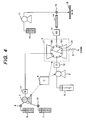
- Fig. 4 shows a diagrammatic view of another example of the present invention.
- the difference from Fig. 1 resides in the addition of means for pipetting. Since a flow rate eluted from the separation column 14 is a nano-flow level (nL/min.), such the small amount of discharged liquid does not make a liquid drop and it is very difficult to pipette the liquid.
- a make-up solution 16 is combined with the solution from the separation column 14 with a make-up pump 17.
- the flow rate of the make-up pump 17 is a micro flow level ( ⁇ L/min.).
- the solution after combination is pipetted (divided) on a pipette plate 19.
- the pipette plate 19 is movable in both front and backward directions and right and left directions as well.
- the flow rate of the eluted solution is a micro-flow level ( ⁇ L/min.), so that the solution becomes liquid drops and pipetting is possible.
- MALDI matrix-laser dislocation ionized
- Fig. 5 and Fig. 6 show diagrammatic views of the improved ten-ports valves for the present invention.
- the ten-ports valve 3 comprises a rotary seal 22, a stator ring 25, a stator seal 24 and a stator, as shown in Fig, 6.
- the thin continuous lines in the circle are grooves formed in the stator seal 24, the switching of the flow passages in the valve being carried out by rotation of this portion.
- the thick continuous lines which are peculiar to this embodiment, are grooves formed in the stator 23.
- An ordinary ten-ports valve employs PEEK, SUS tubes, etc. for the sampling loops 100, 101 and flow passage 21. Since the volume of the sampling loops which deal with the nano-flow rate, about 1 micro-litter, the grooves (100, 101) in the stator can be used in place of the sampling loops.
- the flow passages 21 are the same as the sampling loops. As a result, six screw holes for connecting tubes can be eliminated, and connection of tubes becomes simple. The possibility that dust comes into at the time of tube connection job can be also eliminated.
- the present invention it is not necessary to prepare gradient solutions beforehand for each analysis. It is possible to carry out separation analysis with good reproducibility even at a flow rate of a nano-flow level (nL/min.) by gradient elution. Accordingly, it is possible to provide a liquid chromatography that is capable of continuous analysis for performing the gradient at a nano-flow level (nL/min.).
Landscapes
- Physics & Mathematics (AREA)
- Health & Medical Sciences (AREA)
- Life Sciences & Earth Sciences (AREA)
- Chemical & Material Sciences (AREA)
- Analytical Chemistry (AREA)
- Biochemistry (AREA)
- General Health & Medical Sciences (AREA)
- General Physics & Mathematics (AREA)
- Immunology (AREA)
- Pathology (AREA)
- Sampling And Sample Adjustment (AREA)
Abstract
Description
Claims (7)
- A separation analyzer comprising:wherein there is disposed a flow switching means (3) having a first (100) and second sampling loop (101) for temporarily storing the solutions and comprising a flow passage from the first pump (1), a flow passage from the second pump (2) and a flow passage from the sample introduction section (13), the flow passages being connected with each other, anda first pump (1) for transferring liquid, while changing mixing ratios of plural kinds of solutions (6,7);a second pump (2) for transferring a transfer solution;a sample introduction section (13);a separation column (14) for separating a sample; anda detector (15) for detecting the sample eluted from the separation column (14),
wherein the flow switching means (3) alternatively assumes a first state where the second pump (2) pushes out the solution in the second sampling loop (101) towards the sample introduction section (13), while transferring the solution from the first pump (1) to the first sampling loop (100), and assumes a second state where the second pump (2) pushes out the solution in the first sampling loop (100), towards the sample introduction section (13) while transferring the solution from the first pump (1) to the second sampling loop (101). - The separation analyzer according to claim 1, wherein the flow switching means (3) has a discharge passage for discharging the solution outside of the analyzer, the passage having a flow resistance equivalent to that of the separation column (14), and wherein the first sampling loop (100) is connected with the discharge passage in the first state, and the second sampling loop (101) is connected with the discharge passage in the second state.
- The separation analyzer according to claim 1 or 2, wherein the first pump (1) transfers the solution at a rate of a micro-liter level (µL/min.) and the second pump (2) transfers the solution at a rate of a nano-liter level (nL/min.).
- The separation analyzer according to claim 1, 2 or 3, wherein a volume of each of the first and second sampling loops (100, 101) is about 1 micro-liter (µL).
- The separation analyzer according to claim 2, wherein the flow switching means (3) comprises a first member that comprises a first connection port to which the passage from the first pump (1) is connected, a second connection port to which the passage from the second pump (2) is connected, a third connection port to which the flow passage to the sample introduction section (13) is connected, and a fourth connection port to which the discharge passage is connected, and a second member having a flow switching passage for switching between the first and second states, and
wherein the first and second sampling loops (100, 101) are formed in the first and second members. - The separation analyzer according to any preceding claim, comprising a third pump (17) for transferring the solution at a rate of a micro-liter level (µL/min.), a mixer (18) for mixing the eluted solution from the separation column (14) and the solution transferred from the third pump, and a pipetting section (19) for pipetting the solution after the solutions are mixed by the mixer.
- The separation analyzer according to any preceding claim, which further comprises a constant temperature oven for keeping the temperature of the analyzer constant.
Priority Applications (1)
| Application Number | Priority Date | Filing Date | Title |
|---|---|---|---|
| EP10008245A EP2246697A3 (en) | 2003-03-11 | 2004-02-23 | Separation analyzer |
Applications Claiming Priority (2)
| Application Number | Priority Date | Filing Date | Title |
|---|---|---|---|
| JP2003064319 | 2003-03-11 | ||
| JP2003064319A JP3823092B2 (en) | 2003-03-11 | 2003-03-11 | Separation analyzer |
Publications (2)
| Publication Number | Publication Date |
|---|---|
| EP1457774A1 true EP1457774A1 (en) | 2004-09-15 |
| EP1457774B1 EP1457774B1 (en) | 2010-09-15 |
Family
ID=32767899
Family Applications (2)
| Application Number | Title | Priority Date | Filing Date |
|---|---|---|---|
| EP04004088A Expired - Lifetime EP1457774B1 (en) | 2003-03-11 | 2004-02-23 | Separation analyser |
| EP10008245A Withdrawn EP2246697A3 (en) | 2003-03-11 | 2004-02-23 | Separation analyzer |
Family Applications After (1)
| Application Number | Title | Priority Date | Filing Date |
|---|---|---|---|
| EP10008245A Withdrawn EP2246697A3 (en) | 2003-03-11 | 2004-02-23 | Separation analyzer |
Country Status (4)
| Country | Link |
|---|---|
| US (3) | US7135111B2 (en) |
| EP (2) | EP1457774B1 (en) |
| JP (1) | JP3823092B2 (en) |
| DE (1) | DE602004029114D1 (en) |
Cited By (6)
| Publication number | Priority date | Publication date | Assignee | Title |
|---|---|---|---|---|
| WO2007141718A3 (en) * | 2006-06-09 | 2008-02-14 | Firmenich & Cie | Method and apparatus for providing samples of volatiles to analysis using a multi-port valve and cryo-modulation |
| WO2008150452A1 (en) * | 2007-06-01 | 2008-12-11 | Siemens Energy & Automation, Inc. | Continuous flow sample introduction apparatus and method |
| EP2121188A4 (en) * | 2007-01-26 | 2010-08-25 | Teledyne Isco Inc | Valve |
| WO2014000778A1 (en) * | 2012-06-26 | 2014-01-03 | Agilent Technologies, Inc. | Fluidic valve with selectively switchable storage paths |
| CN103512985A (en) * | 2012-06-21 | 2014-01-15 | 株式会社岛津制作所 | Mobile phase delivery device and liquid chromatograph |
| CN104897822A (en) * | 2014-03-04 | 2015-09-09 | 株式会社岛津制作所 | Liquid chromatograph control system and liquid chromatograph control method |
Families Citing this family (28)
| Publication number | Priority date | Publication date | Assignee | Title |
|---|---|---|---|---|
| JP4077674B2 (en) * | 2002-07-24 | 2008-04-16 | 憲一 工藤 | Gradient liquid feeding device and liquid feeding method for nano / micro liquid chromatograph |
| JP4377761B2 (en) * | 2004-07-01 | 2009-12-02 | 株式会社日立ハイテクノロジーズ | Liquid chromatograph |
| JP3898688B2 (en) * | 2003-11-07 | 2007-03-28 | 株式会社日立ハイテクノロジーズ | Gradient liquid feeder |
| JP4254958B2 (en) * | 2004-06-09 | 2009-04-15 | 株式会社日立ハイテクノロジーズ | Gradient liquid feeding system |
| US8881582B2 (en) * | 2005-01-31 | 2014-11-11 | Waters Technologies Corporation | Method and apparatus for sample injection in liquid chromatography |
| JP4467454B2 (en) * | 2005-03-31 | 2010-05-26 | 株式会社日立ハイテクノロジーズ | Multidimensional liquid chromatograph and analysis method using the same |
| US9103814B2 (en) * | 2006-03-17 | 2015-08-11 | Waters Technologies Corporation | Solvent delivery system for liquid chromatography that maintains fluid integrity and pre-forms gradients |
| JP4253667B2 (en) * | 2006-06-02 | 2009-04-15 | 株式会社日立ハイテクノロジーズ | Separation analyzer |
| US20080308494A1 (en) * | 2007-05-30 | 2008-12-18 | Groton Biosystems, Llc | Fluid sampling interface apparatus |
| ITVE20070072A1 (en) * | 2007-10-16 | 2009-04-17 | Dani Instr Spa | DEVICE FOR THE GENERATION OF MOBILE PHASE GRADIENTS WITH MICRO- AND NANOFLUSSI FOR HIGH-PERFORMANCE LIQUID CHROMATOGRAPHY. |
| US8961783B2 (en) * | 2008-09-12 | 2015-02-24 | Waters Technologies Corporation | Apparatus and methods for preparative liquid chromatography |
| JP2010085146A (en) * | 2008-09-30 | 2010-04-15 | Hitachi High-Technologies Corp | Gradient liquid feeding apparatus, gradient liquid feeding system, and liquid chromatograph |
| WO2011001460A1 (en) * | 2009-06-29 | 2011-01-06 | 株式会社島津製作所 | Flow path switching valve |
| US20120145937A1 (en) * | 2010-12-13 | 2012-06-14 | Richman Bruce A | Rotary valve for sample handling in fluid analysis |
| US9228982B2 (en) * | 2011-09-16 | 2016-01-05 | Agilent Technologies, Inc. | Single injection valve for HPLC combining sample introduction, wash cycles and diagnosis |
| CN103969348B (en) * | 2013-01-29 | 2018-01-09 | 深圳普门科技有限公司 | The bubble suppressing method and its testing instruments of a kind of medical test instrument |
| JP6207872B2 (en) * | 2013-04-18 | 2017-10-04 | 株式会社日立ハイテクノロジーズ | Liquid chromatograph apparatus and liquid chromatograph analysis method |
| WO2016082154A1 (en) * | 2014-11-27 | 2016-06-02 | 王峰 | Liquid phase chromatograph |
| JP6651238B2 (en) * | 2014-12-15 | 2020-02-19 | ジーイー・ヘルスケア・バイオサイエンス・アクチボラグ | Rotary valves and systems |
| EP3093335A1 (en) * | 2015-05-13 | 2016-11-16 | Bayer Technology Services GmbH | Process control system for regulating and controlling a modular system for the production of biopharmaceutical and biological macromolecular products |
| EP3368892B1 (en) * | 2015-10-31 | 2024-04-03 | Mls Acq, Inc. D/B/A Max Analytical Technologies | Analysis system for analyzing samples from a sample source, and analysis method |
| EP4198508B1 (en) | 2016-09-28 | 2025-10-22 | Evosep ApS | Chromatographic analysis with low pressure dual gradient refocusing |
| US12298284B2 (en) | 2016-09-28 | 2025-05-13 | Evosep Aps | System for subjecting a sample to chromatographic analysis |
| US10487954B2 (en) * | 2017-02-03 | 2019-11-26 | Micromeritics Instrument Corporation | Blend valve |
| US20190227040A1 (en) * | 2018-01-22 | 2019-07-25 | Thermo Finnigan Llc | Method and Apparatus for Chromatograph Nano-Flow Fractionator |
| US11573212B2 (en) * | 2018-06-18 | 2023-02-07 | Shimadzu Corporation | Flow channel mechanism and liquid chromatograph including the same |
| US12360088B2 (en) * | 2020-02-21 | 2025-07-15 | Shimadzu Corporation | Liquid chromatograph |
| GB2635329A (en) * | 2023-11-06 | 2025-05-14 | Agilent Technologies Inc | Sample separation device with fluid drive unit decoupling |
Citations (5)
| Publication number | Priority date | Publication date | Assignee | Title |
|---|---|---|---|---|
| US4352780A (en) * | 1979-07-13 | 1982-10-05 | Fiatron Systems, Inc. | Device for controlled injection of fluids |
| DE4018928A1 (en) * | 1990-06-13 | 1991-12-19 | Bodenseewerk Perkin Elmer Co | Liquid specimens in carrier liquid flow, entering arrangement - has two specimen loops connected via valve enabling injection of different vol. |
| US5968367A (en) * | 1996-01-19 | 1999-10-19 | Cohesive Technologies, Inc. | High performance liquid chromatography method and apparatus |
| JP2002071657A (en) | 2000-08-29 | 2002-03-12 | Jasco Corp | Gradient liquid chromatogram measuring device and measuring method |
| US6502448B1 (en) * | 1999-09-07 | 2003-01-07 | Edward Rapkin | Chromatography detection system and method |
Family Cites Families (11)
| Publication number | Priority date | Publication date | Assignee | Title |
|---|---|---|---|---|
| US4158630A (en) * | 1978-02-24 | 1979-06-19 | Stearns Stanley D | Chromatographic multi-sample valving apparatus |
| DE4104075C1 (en) | 1991-02-11 | 1992-03-19 | Bruker Analytische Messtechnik Gmbh, 7512 Rheinstetten, De | |
| US5462660A (en) | 1994-04-22 | 1995-10-31 | The United States Of America As Represented By The Secretary Of Agriculture | High performance liquid chromatography injection system for the simultaneous concentration and analysis of trace components |
| DE69530669T2 (en) * | 1995-02-18 | 2003-11-27 | Agilent Technologies Deutschla | Mixing liquids using electroosmosis |
| US5935443A (en) * | 1995-03-03 | 1999-08-10 | Alltech Associates, Inc. | Electrochemically regenerated ion neutralization and concentration devices and systems |
| US5958227A (en) * | 1997-07-15 | 1999-09-28 | Tosoh Corporation | Liquid chromatograph apparatus with a switching valve |
| US6989129B2 (en) * | 2001-04-05 | 2006-01-24 | The President And Fellows Of Harvard College | Automated capillary liquid chromatography small volume analysis system |
| US7588725B2 (en) * | 2001-04-25 | 2009-09-15 | Biotrove, Inc. | High throughput autosampler |
| US7066011B2 (en) | 2001-06-07 | 2006-06-27 | Nano Solution, Inc. | Liquid chromatograph and analysis system |
| JP4603203B2 (en) * | 2001-07-02 | 2010-12-22 | 積水化学工業株式会社 | Liquid chromatograph |
| JP3816883B2 (en) * | 2003-03-06 | 2006-08-30 | 株式会社日立ハイテクノロジーズ | Liquid chromatograph mass spectrometer |
-
2003
- 2003-03-11 JP JP2003064319A patent/JP3823092B2/en not_active Expired - Fee Related
-
2004
- 2004-02-12 US US10/776,263 patent/US7135111B2/en not_active Expired - Fee Related
- 2004-02-23 EP EP04004088A patent/EP1457774B1/en not_active Expired - Lifetime
- 2004-02-23 DE DE602004029114T patent/DE602004029114D1/en not_active Expired - Lifetime
- 2004-02-23 EP EP10008245A patent/EP2246697A3/en not_active Withdrawn
-
2006
- 2006-10-16 US US11/581,147 patent/US7699990B2/en not_active Expired - Fee Related
-
2010
- 2010-01-12 US US12/685,724 patent/US8048312B2/en not_active Expired - Fee Related
Patent Citations (5)
| Publication number | Priority date | Publication date | Assignee | Title |
|---|---|---|---|---|
| US4352780A (en) * | 1979-07-13 | 1982-10-05 | Fiatron Systems, Inc. | Device for controlled injection of fluids |
| DE4018928A1 (en) * | 1990-06-13 | 1991-12-19 | Bodenseewerk Perkin Elmer Co | Liquid specimens in carrier liquid flow, entering arrangement - has two specimen loops connected via valve enabling injection of different vol. |
| US5968367A (en) * | 1996-01-19 | 1999-10-19 | Cohesive Technologies, Inc. | High performance liquid chromatography method and apparatus |
| US6502448B1 (en) * | 1999-09-07 | 2003-01-07 | Edward Rapkin | Chromatography detection system and method |
| JP2002071657A (en) | 2000-08-29 | 2002-03-12 | Jasco Corp | Gradient liquid chromatogram measuring device and measuring method |
Non-Patent Citations (1)
| Title |
|---|
| BUNSEKI KAGAKU, vol. 50, 2001, pages 825 |
Cited By (11)
| Publication number | Priority date | Publication date | Assignee | Title |
|---|---|---|---|---|
| WO2007141718A3 (en) * | 2006-06-09 | 2008-02-14 | Firmenich & Cie | Method and apparatus for providing samples of volatiles to analysis using a multi-port valve and cryo-modulation |
| EP2121188A4 (en) * | 2007-01-26 | 2010-08-25 | Teledyne Isco Inc | Valve |
| WO2008150452A1 (en) * | 2007-06-01 | 2008-12-11 | Siemens Energy & Automation, Inc. | Continuous flow sample introduction apparatus and method |
| US7950296B2 (en) | 2007-06-01 | 2011-05-31 | Siemens Industry, Inc. | Continuous flow sample introduction apparatus and method |
| CN103512985A (en) * | 2012-06-21 | 2014-01-15 | 株式会社岛津制作所 | Mobile phase delivery device and liquid chromatograph |
| CN103512985B (en) * | 2012-06-21 | 2016-01-06 | 株式会社岛津制作所 | Mobile phase liquid feeding device and liquid chromatograph |
| WO2014000778A1 (en) * | 2012-06-26 | 2014-01-03 | Agilent Technologies, Inc. | Fluidic valve with selectively switchable storage paths |
| CN104395748A (en) * | 2012-06-26 | 2015-03-04 | 安捷伦科技有限公司 | Fluidic valve with selectively switchable storage paths |
| US9335309B2 (en) | 2012-06-26 | 2016-05-10 | Agilent Technologies, Inc. | Fluidic valve with selectively switchable storage paths |
| CN104395748B (en) * | 2012-06-26 | 2017-09-15 | 安捷伦科技有限公司 | Flow control valve with the store path optionally switched |
| CN104897822A (en) * | 2014-03-04 | 2015-09-09 | 株式会社岛津制作所 | Liquid chromatograph control system and liquid chromatograph control method |
Also Published As
| Publication number | Publication date |
|---|---|
| EP2246697A3 (en) | 2011-05-18 |
| US20100107782A1 (en) | 2010-05-06 |
| DE602004029114D1 (en) | 2010-10-28 |
| US7135111B2 (en) | 2006-11-14 |
| US8048312B2 (en) | 2011-11-01 |
| US20040178133A1 (en) | 2004-09-16 |
| JP3823092B2 (en) | 2006-09-20 |
| EP2246697A2 (en) | 2010-11-03 |
| JP2004271409A (en) | 2004-09-30 |
| EP1457774B1 (en) | 2010-09-15 |
| US7699990B2 (en) | 2010-04-20 |
| US20070031285A1 (en) | 2007-02-08 |
Similar Documents
| Publication | Publication Date | Title |
|---|---|---|
| US7135111B2 (en) | Separation analyzer | |
| US20230135114A1 (en) | Sample Injector With Metering Device Balancing Pressure Differences In An Intermediate Valve State | |
| CN104285145B (en) | The two dimensional fluid using controlled pressure separates | |
| EP0022654B1 (en) | Liquid handling device | |
| CN104903721B (en) | The analysis of I phases and II phases metabolin and parent compound | |
| JP6843932B2 (en) | Sample injector | |
| CN112180021B (en) | Liquid Chromatography System | |
| WO2005011832A2 (en) | A simultaneous multi-colum liquid chromatograph for direct sampling of an array of liquid samples | |
| US7347936B2 (en) | Liquid chromatograph | |
| JP2020038205A5 (en) | ||
| EP1879026A1 (en) | Focussing a sample on an analytical column | |
| EP1408330A1 (en) | Liquid chromatograph and analyzing system | |
| CN112672799B (en) | Two-dimensional fluid separation with push-pull modulation | |
| JP7357787B2 (en) | Control method for automatic analyzer | |
| CN209961743U (en) | Nano-flow fractionator device | |
| JP2006227029A (en) | Separation analyzer | |
| US20240213014A1 (en) | System and method for delivery of an analyte and a reference | |
| JPH0712790A (en) | Process gas chromatograph |
Legal Events
| Date | Code | Title | Description |
|---|---|---|---|
| PUAI | Public reference made under article 153(3) epc to a published international application that has entered the european phase |
Free format text: ORIGINAL CODE: 0009012 |
|
| AK | Designated contracting states |
Kind code of ref document: A1 Designated state(s): AT BE BG CH CY CZ DE DK EE ES FI FR GB GR HU IE IT LI LU MC NL PT RO SE SI SK TR |
|
| AX | Request for extension of the european patent |
Extension state: AL LT LV MK |
|
| 17P | Request for examination filed |
Effective date: 20050310 |
|
| AKX | Designation fees paid |
Designated state(s): DE GB |
|
| 17Q | First examination report despatched |
Effective date: 20090319 |
|
| GRAP | Despatch of communication of intention to grant a patent |
Free format text: ORIGINAL CODE: EPIDOSNIGR1 |
|
| GRAS | Grant fee paid |
Free format text: ORIGINAL CODE: EPIDOSNIGR3 |
|
| GRAA | (expected) grant |
Free format text: ORIGINAL CODE: 0009210 |
|
| AK | Designated contracting states |
Kind code of ref document: B1 Designated state(s): DE GB |
|
| REG | Reference to a national code |
Ref country code: GB Ref legal event code: FG4D |
|
| REF | Corresponds to: |
Ref document number: 602004029114 Country of ref document: DE Date of ref document: 20101028 Kind code of ref document: P |
|
| PLBE | No opposition filed within time limit |
Free format text: ORIGINAL CODE: 0009261 |
|
| STAA | Information on the status of an ep patent application or granted ep patent |
Free format text: STATUS: NO OPPOSITION FILED WITHIN TIME LIMIT |
|
| 26N | No opposition filed |
Effective date: 20110616 |
|
| REG | Reference to a national code |
Ref country code: DE Ref legal event code: R097 Ref document number: 602004029114 Country of ref document: DE Effective date: 20110616 |
|
| PGFP | Annual fee paid to national office [announced via postgrant information from national office to epo] |
Ref country code: DE Payment date: 20160216 Year of fee payment: 13 |
|
| PGFP | Annual fee paid to national office [announced via postgrant information from national office to epo] |
Ref country code: GB Payment date: 20160217 Year of fee payment: 13 |
|
| REG | Reference to a national code |
Ref country code: DE Ref legal event code: R119 Ref document number: 602004029114 Country of ref document: DE |
|
| GBPC | Gb: european patent ceased through non-payment of renewal fee |
Effective date: 20170223 |
|
| PG25 | Lapsed in a contracting state [announced via postgrant information from national office to epo] |
Ref country code: DE Free format text: LAPSE BECAUSE OF NON-PAYMENT OF DUE FEES Effective date: 20170901 |
|
| PG25 | Lapsed in a contracting state [announced via postgrant information from national office to epo] |
Ref country code: GB Free format text: LAPSE BECAUSE OF NON-PAYMENT OF DUE FEES Effective date: 20170223 |