EP1457667A1 - Fuel supply pump which is lubricated by the fuel - Google Patents
Fuel supply pump which is lubricated by the fuel Download PDFInfo
- Publication number
- EP1457667A1 EP1457667A1 EP04005693A EP04005693A EP1457667A1 EP 1457667 A1 EP1457667 A1 EP 1457667A1 EP 04005693 A EP04005693 A EP 04005693A EP 04005693 A EP04005693 A EP 04005693A EP 1457667 A1 EP1457667 A1 EP 1457667A1
- Authority
- EP
- European Patent Office
- Prior art keywords
- fuel
- supply pump
- low
- pressure
- plunger
- Prior art date
- Legal status (The legal status is an assumption and is not a legal conclusion. Google has not performed a legal analysis and makes no representation as to the accuracy of the status listed.)
- Granted
Links
- 239000000446 fuel Substances 0.000 title claims abstract description 211
- 238000005086 pumping Methods 0.000 claims abstract 4
- 239000000314 lubricant Substances 0.000 claims description 17
- 238000002485 combustion reaction Methods 0.000 claims description 4
- 238000005461 lubrication Methods 0.000 abstract description 69
- 230000001050 lubricating effect Effects 0.000 abstract description 7
- 230000000087 stabilizing effect Effects 0.000 abstract description 3
- 239000002828 fuel tank Substances 0.000 description 13
- 239000002184 metal Substances 0.000 description 12
- 230000002093 peripheral effect Effects 0.000 description 11
- 239000003921 oil Substances 0.000 description 9
- 238000002347 injection Methods 0.000 description 8
- 239000007924 injection Substances 0.000 description 8
- 230000000694 effects Effects 0.000 description 6
- 238000010586 diagram Methods 0.000 description 4
- 230000000903 blocking effect Effects 0.000 description 1
- 230000036461 convulsion Effects 0.000 description 1
- 238000001816 cooling Methods 0.000 description 1
- 230000001747 exhibiting effect Effects 0.000 description 1
- 239000000295 fuel oil Substances 0.000 description 1
- 238000000034 method Methods 0.000 description 1
- 238000012986 modification Methods 0.000 description 1
- 230000004048 modification Effects 0.000 description 1
Images


Classifications
-
- F—MECHANICAL ENGINEERING; LIGHTING; HEATING; WEAPONS; BLASTING
- F02—COMBUSTION ENGINES; HOT-GAS OR COMBUSTION-PRODUCT ENGINE PLANTS
- F02M—SUPPLYING COMBUSTION ENGINES IN GENERAL WITH COMBUSTIBLE MIXTURES OR CONSTITUENTS THEREOF
- F02M59/00—Pumps specially adapted for fuel-injection and not provided for in groups F02M39/00 -F02M57/00, e.g. rotary cylinder-block type of pumps
- F02M59/02—Pumps specially adapted for fuel-injection and not provided for in groups F02M39/00 -F02M57/00, e.g. rotary cylinder-block type of pumps of reciprocating-piston or reciprocating-cylinder type
- F02M59/10—Pumps specially adapted for fuel-injection and not provided for in groups F02M39/00 -F02M57/00, e.g. rotary cylinder-block type of pumps of reciprocating-piston or reciprocating-cylinder type characterised by the piston-drive
- F02M59/102—Mechanical drive, e.g. tappets or cams
-
- F—MECHANICAL ENGINEERING; LIGHTING; HEATING; WEAPONS; BLASTING
- F02—COMBUSTION ENGINES; HOT-GAS OR COMBUSTION-PRODUCT ENGINE PLANTS
- F02M—SUPPLYING COMBUSTION ENGINES IN GENERAL WITH COMBUSTIBLE MIXTURES OR CONSTITUENTS THEREOF
- F02M63/00—Other fuel-injection apparatus having pertinent characteristics not provided for in groups F02M39/00 - F02M57/00 or F02M67/00; Details, component parts, or accessories of fuel-injection apparatus, not provided for in, or of interest apart from, the apparatus of groups F02M39/00 - F02M61/00 or F02M67/00; Combination of fuel pump with other devices, e.g. lubricating oil pump
- F02M63/0001—Fuel-injection apparatus with specially arranged lubricating system, e.g. by fuel oil
-
- F—MECHANICAL ENGINEERING; LIGHTING; HEATING; WEAPONS; BLASTING
- F02—COMBUSTION ENGINES; HOT-GAS OR COMBUSTION-PRODUCT ENGINE PLANTS
- F02M—SUPPLYING COMBUSTION ENGINES IN GENERAL WITH COMBUSTIBLE MIXTURES OR CONSTITUENTS THEREOF
- F02M63/00—Other fuel-injection apparatus having pertinent characteristics not provided for in groups F02M39/00 - F02M57/00 or F02M67/00; Details, component parts, or accessories of fuel-injection apparatus, not provided for in, or of interest apart from, the apparatus of groups F02M39/00 - F02M61/00 or F02M67/00; Combination of fuel pump with other devices, e.g. lubricating oil pump
- F02M63/02—Fuel-injection apparatus having several injectors fed by a common pumping element, or having several pumping elements feeding a common injector; Fuel-injection apparatus having provisions for cutting-out pumps, pumping elements, or injectors; Fuel-injection apparatus having provisions for variably interconnecting pumping elements and injectors alternatively
- F02M63/0225—Fuel-injection apparatus having a common rail feeding several injectors ; Means for varying pressure in common rails; Pumps feeding common rails
Definitions
- the present invention relates to a fuel supply pump for an internal combustion engine (hereinafter referred to as an engine).
- An accumulator fuel injection system as shown in Fig 4 is conventionally used as a diesel engine fuel injection system.
- the accumulator fuel injection system includes an accumulator (common rail) 100, in which a high-pressure fuel, supplied under pressure by a fuel supply pump 101, is accumulated.
- the high-pressure fuel in the common rail 100 is injected into each cylinder of the diesel engine through a fuel injection valve (injector) 102.
- a fuel supply pump 101 includes a low-pressure supply pump 103, pump elements, such as a plunger 104, a plunger drive means, etc.
- the fuel in a fuel tank 105 is pumped by the low-pressure supply pump 103 and is supplied to a pressure chamber 106.
- the fuel supplied to the pressure chamber 106 is increased to high pressure by the reciprocating motion of the plunger 104 and is supplied to the common rail 100 under pressure.
- the reciprocating motion of the plunger 104 is activated by the plunger drive means.
- the plunger drive means includes a drive shaft (cam shaft) 107 connected to an engine crankshaft and rotatively driven by the engine, a cam 108 assembled eccentrically on the cam shaft 107, a cam ring 109 driven by the cam 108 through a metal bushing (not shown) and revolved (orbited) about the center of the cam shaft 107, etc.
- a sliding surface 110 of the cam ring 109 is kept in pressure contact with a sliding surface 112 of the plunger 104 by an urging means 111.
- the plunger 104 is reciprocated by the orbiting of the cam ring 109 and the pressure of the urging means 111. In the process, the sliding surface 112 of the plunger 104 slides over the sliding surface 110 of the cam ring 109.
- the low-pressure supply pump 103 sucks in the low-pressure fuel from the fuel tank 105 and discharges it to the pressure chamber 106.
- the low-pressure fuel discharged from the low-pressure supply pump 103 is supplied to the sliding portion.
- the lubricity of a sliding portion in the plunger drive means such as a sliding portion between a metal bushing and the cam 108, is improved (for example, Japanese Unexamined Patent Publication No. 2002-310039).
- the lubricity between a metal bushing 113 and the cam shaft 107 is maintained by the low-pressure fuel leaking from the low-pressure supply pump 103.
- the low-pressure fuel oil supplied by leakage varies in flow rate thereof such that the lubricating conditions are liable to vary.
- the object of this invention is to provide a fuel supply pump in which the lubricating conditions of the bearing portion of the drive shaft (cam shaft) do not vary.
- a fuel supply pump comprising a sliding portion lubrication oil path for supplying part of the fuel discharged from a low-pressure supply pump to sliding portions between a plunger and a plunger drive means, and a bearing portion lubrication oil path for supplying to bearing portions of the drive shaft with the fuel supplied to the sliding portions between the plunger and the plunger drive means.
- the low-pressure fuel can be forcibly supplied to the bearing portions of the drive shaft utilizing the discharge pressure of the low-pressure supply pump (the low-pressure fuel supplied to the bearing portions and the sliding portions is hereinafter referred to as the lubrication fuel) and, therefore the flow rate of the lubrication fuel supplied to the bearing portions does not vary and the lubricating conditions of the bearing portions can be stabilized.
- a fuel supply pump in which the fuel supplied to the bearing portions of the drive shaft is sucked in by the low-pressure supply pump.
- a fuel supply pump comprising a throttle arranged in the bearing portion lubrication path and restricting the flow rate of the fuel sucked in by the low-pressure supply pump from the bearing portions of the drive shaft.
- the lubrication fuel can be prevented from being excessively sucked in by the low-pressure supply pump, and the temperature increase of the lubrication fuel can be suppressed.
- a fuel supply pump comprising a sliding portion lubrication oil path for supplying part of a fuel discharged from a low-pressure supply pump to sliding portions between a plunger and a plunger drive means, and a bearing portion lubrication oil path branching from the sliding portion lubrication oil path and supplying part of the fuel, flowing to the sliding portions between the plunger and the plunger drive means, to bearing portions of a drive shaft.
- the lubrication fuel supplied to the bearing portions comes directly from a fuel tank and, therefore, is low in temperature. Therefore, the cooling effect can be increased.
- a fuel supply pump wherein the bearing portion lubrication oil path includes a throttle for restricting the flow rate of the fuel supplied to the bearing portions of the drive shaft.
- the fuel supply pump comprises: a bearing portion lubrication oil path for supplying part of a fuel discharged from a low-pressure supply pump to bearing portions of a drive shaft; a sliding portion lubrication oil path for supplying sliding portions between a plunger and a plunger drive means with the fuel supplied to the bearing portions of the drive shaft; and a throttle arranged in the bearing portion lubrication oil path and restricting the flow rate of the fuel supplied to the bearing portions of the drive shaft.
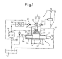
- a first embodiment of the invention is explained with reference to Fig. 1.
- a fuel supply pump 1 according to the first embodiment is used with an accumulator fuel injection system.
- An accumulator fuel injection system 10 to which the fuel supply pump 1 according to the invention is applied comprises a fuel supply pump 1, a common rail 11, an injector 12, etc.
- a low-pressure fuel sucked in from a fuel tank 13 is increased in pressure and discharged as a high-pressure fuel by the fuel supply pump 1.
- the common rail 11 accumulates the high-pressure fuel discharged from the fuel supply pump 1, and distributes it to the injector 12 of each cylinder of a diesel engine or the like mounted on a vehicle such as an automobile.
- the injector 12 supplies, by injecting, the high-pressure fuel to each cylinder of the engine at a predetermined timing for a predetermined length of time in response to a command from an engine control unit (not shown).
- the fuel supply pump 1 includes a pump element 2, a metering valve 14, a low-pressure supply pump 15, a plunger drive means 3 (hereinafter referred to as the drive means 3), etc.
- the pump element 2 including a plunger 21, a cylinder 22, etc. is the most important part exhibiting the function as a high-pressure supply pump for increasing the pressure of the low-pressure fuel to a high pressure and supplying the high-pressure fuel to the common rail 11.
- the plunger 21, which reciprocates in the cylinder 22, increases the pressure of the low-pressure fuel and supplies a high-pressure fuel to the common rail 11.
- a plunger head 23 having a larger diameter than the cylinder 22 is formed at the end of the plunger 21 nearer to the drive means 3.
- the end surface of the plunger head 23 nearer to the drive means 3 is machined in a flat form and constitutes a sliding surface 24 with the drive means 3.
- the plunger head 23 is connected with a spring 25 for urging the plunger 21 toward the drive means 3. By the urging operation of the spring 25, the sliding surface 24 is brought into pressure contact with a sliding surface 31 of the drive means 3.
- the cylinder 22 supports the plunger 21 so that the plunger 21 can reciprocate.
- a pressure chamber 26 is formed between an inner peripheral surface of the cylinder 22, an end surface of the plunger 21 farther to the driven means 3, etc.
- the low-pressure fuel introduced into the pressure chamber 26 is increased in pressure by the plunger 21.
- An inlet-side fuel path to the pressure chamber 26 and an outlet-side fuel path from the pressure chamber 26 have check valves 27 and 28, respectively, for blocking the reverse flow of the fuel.
- the metering valve 14 is a normally-open solenoid valve, which by adjusting the opening degree (the lift amount of the valve body or the valve-port opening area) of a fuel path formed therein, controls the flow rate of the low-pressure fuel supplied from the low-pressure supply pump 15 to the pressure chamber 26.
- the opening degree of the fuel path is adjusted in accordance with an instruction of the engine control unit.
- the low-pressure supply pump 15 is a feed pump for sucking in the low-pressure fuel from the fuel tank 13 and supplying it to the pressure chamber 26 through the metering valve 14.
- the low-pressure supply pump 15 is arranged at an end portion of a drive shaft 32 making up the drive means 3 and is driven by the driving force transmitted from the drive shaft 32.
- the drive means 3 is a plunger drive means having the drive shaft 32 rotatively driven by the engine and reciprocating the plunger 21 in accordance with the rotation of the drive shaft 32.
- the drive means 3 includes the drive shaft (cam shaft) 32, a cam 33, a cam ring 34, etc.
- An end portion of the cam shaft 32 farther from the low-pressure supply pump 15 is connected to a crankshaft (not shown) of the engine and is rotatively driven by the engine.
- the cam shaft 32 is accommodated in and supported by a pump housing (not shown) through metal bushings 35, 36.
- the metal bushing 35 is mounted on a part of the housing nearer to the crankshaft, while the metal bushing 36 is mounted on a part of the housing nearer to the low-pressure supply pump 15.
- An inner peripheral surface of the metal bushing 36 nearer to the low-pressure pump 15 and an outer peripheral surface of the cam shaft 32 make up a bearing portion of the cam shaft 32 (hereinafter simply referred to as the bearing portion).
- the bearing portion When the cam shaft 32 is rotatively driven by the engine, the outer peripheral surface of the cam shaft 32 slides on the inner peripheral surface of the metal bushing 36.
- the cam 33 is a column having a circular section, is assembled eccentrically on the cam shaft 32, and revolves (orbits) about the center of the cam shaft 32 in operatively interlocked relation with the rotation of the cam shaft 32.
- the cam ring 34 is a tube with a substantially regular polygonal section, having a plurality of flat surfaces, formed on the outer surface of the tube and being in parallel to the axial center of the cam 33.
- a cam 33 is accommodated in the inside of the tube of the cam ring 34 through a metal bushing (not shown).
- the flat surfaces formed on the outer surface of the cam ring 34 make up the sliding surface 31 on which the sliding surface 24 of the plunger head 23 slide.
- the plunger head 23 is urged toward the sliding surface 31 by the spring 25, so that the sliding surface 24 is kept in pressure contact with the siding surface 31.
- the cam ring 34 orbits about the center of the cam shaft 32 without changing the direction of each flat surface of the sliding surface 31.
- the plunger head 23 slides while relatively reciprocating back and forth on the sliding surface 31, in Fig. 1.
- the outer peripheral surface of the cam 33 slides on the inner peripheral surface of the metal bushing inserted in the cam ring 34 (the sliding surface 24 of the plunger head 23, the sliding surface 31 of the cam ring 34, the outer peripheral surface of the cam 33 and the inner peripheral surface of the metal bushing inserted in the cam ring 34 are hereinafter referred to collectively as the sliding portion).
- a sliding portion lubricant path for supplying the lubrication fuel to the sliding portion includes a pump cam chamber 37, a fuel path connecting the pump cam chamber 37 and an outlet of the low-pressure supply pump 15, etc.
- the pump cam chamber 37 accommodates the plunger head 23, the spring 25, the cam 33, the cam ring 34, etc.
- Part of the low-pressure fuel discharged from the low-pressure supply pump 15 is supplied to the pump cam chamber 37 as a lubrication fuel, and all the sliding portions are immersed in the lubrication fuel. As a result, the lubricity of the sliding portions is maintained.
- the bearing portion lubricant path for supplying the lubrication fuel to the bearing portions includes a fuel film portion 38, a fuel intake path 39, an orifice 16, etc.
- the fuel film portion 38 is formed in a minuscule gap between the inner peripheral surface of the metal bushing 36 and the outer peripheral surface of the cam shaft 32, and is filled with the lubrication fuel.
- the lubrication fuel in the pump cam chamber 37 flows into the fuel film portion 38 which communicates with the pump cam chamber 37.
- the lubrication fuel is filled, as a film, to maintain the lubricity of the bearing portion.
- the fuel intake path 39 is a fuel path for connecting the fuel film portion 38 and an inlet of the low-pressure supply pump 15.
- the low-pressure supply pump 15 constantly sucks in the lubrication fuel from the fuel film portion 38.
- the orifice 16 is arranged in the fuel intake path 39, and restricts the flow rate of the lubrication fuel sucked in from the fuel film portion 38 by the low-pressure supply pump 15. As a result, that part of the lubrication fuel supplied to the pump cam chamber 37 which fails to be sucked in by the low-pressure pump 15 passes through an overflow path 17 and returns to the fuel tank 13.
- part of the low-pressure fuel discharged from the low-pressure supply pump 15 is supplied to the pump cam chamber 37.
- the low-pressure fuel supplied to the pump cam chamber 37 is used as a lubrication fuel for the sliding portions.
- Part of the lubrication fuel in the pump cam chamber 37 is sucked in by the low-pressure supply pump 15 from the fuel film portion 38.
- the lubrication fuel sucked in by the low-pressure supply pump 15 is used as a lubrication fuel for the bearing portions.
- the low-pressure fuel discharged from the low-pressure supply pump 15 is supplied to the pump cam chamber 37 as a lubrication fuel for the sliding portion and, further, part of the lubrication fuel in the pump cam chamber 37 is sucked in by the low-pressure supply pump 15 from the fuel film portion 38.
- the lubrication fuel can be forcibly supplied to the bearing portions using the low-pressure supply pump 15.
- the lubrication fuel can be supplied to the bearing portions at a flow rate free of variations and, thereby, stabilizing the lubricating conditions of the bearing portions.
- the provision of the orifice 16 in the fuel intake path 39 prevents the lubrication fuel from being excessively sucked in by the low-pressure supply pump 15. As a result, the lubrication fuel in the pump cam chamber 37 can be prevented from increasing in temperature.
- the low-pressure supply pump 15 without the flow rate restriction by the orifice 16 or the like, a major portion of the lubrication fuel would be sucked in by the low-pressure supply pump 15 and continue to circulate through the pump cam chamber 37, the fuel film portion 38 and the fuel intake path 39, with the probable result that the temperature of the lubrication fuel is increased by the heat generated in the sliding portions and the bearing portions.
- the low-pressure fuel, low in temperature, from the fuel tank 13 can be sucked in a greater flow rate, thereby making it possible to prevent the lubrication fuel from increasing in temperature.
- a bearing portion lubricant path includes a fuel branch supply path 18, an orifice 16, a fuel film portion 38, etc.
- a sliding portion lubricant path is so configured that part of the low-pressure fuel discharged from a low-pressure supply pump 15 is introduced to a pump cam chamber 37 as a lubrication fuel for the sliding portions.
- the fuel branch supply path 18, as shown in Fig. 2 branches from a fuel path leading from the low-pressure supply pump 15 to the pump cam chamber 37.
- a fuel path leading from the low-pressure supply pump 15 toward the pump cam chamber 37 constitutes a part of the sliding portion lubricant path.
- the fuel branch supply path 18 has the orifice 16 for restricting the flow rate of the lubrication fuel discharged from the low-pressure supply pump 15 and flowing toward the fuel film portion 38, i.e. the bearing portions.
- the lubrication fuel led to the fuel film portion 38 flows into the pump cam chamber 37, and together with the lubrication fuel supplied directly to the pump cam chamber 37, i.e. the lubrication fuel for the sliding portion, returns to the fuel tank 13 through an overflow path 17.
- part of the low-pressure fuel discharged from the low-pressure supply pump 15 toward the pump cam chamber 37, which branches and is led to the fuel film portion 38, is used as a lubrication fuel for the bearing portions.
- the lubrication fuel can be forcibly supplied to the bearing portions using the low-pressure supply pump 15.
- the lubrication fuel can be supplied to the bearing portions a flow rate free of irregularities, thereby stabilizing the lubricating conditions of the bearing portions.
- the bearing portion can be cooled more effectively.
- the provision of the orifice 16 in the fuel branch supply path 18 prevents the lubrication fuel from being supplied in an excessive amount to the bearing portions. In this way, the sliding portions are prevented from being insufficiently lubricated or insufficiently cooled.
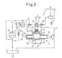
- a bearing portion lubricant path includes a fuel supply path 19, an orifice 16, a fuel film portion 38, etc.
- the fuel supply path 19, as shown in Fig. 3, is a fuel path whereby part of the low-pressure fuel discharged from a low-pressure supply pump 15 is led to a fuel film portion 38 as a lubrication fuel for the bearing portions and the sliding portions.
- the lubrication fuel after flowing through the fuel film portion 38 and the pump cam chamber 37 in that order, is returned to a fuel tank 13 through an overflow path 17.
- the fuel supply path 19 has an orifice 16 for restricting the flow rate of the lubrication fuel flowing toward the fuel film portion 38 and the pump cam chamber 37.
- the whole of the low-pressure fuel discharged from the low-pressure supply pump 15 and flowing toward the pump cam chamber 37 is first led to the fuel film portion 38 and is used as a lubrication fuel for the bearing portions. After that, the low-pressure fuel is supplied from the fuel film portion 38 into the pump cam chamber 37 and is used as a lubrication fuel for the sliding portions.
- the lubrication fuel discharged from the low-pressure supply pump 15 and flowing toward the pump cam chamber 37 is wholly led first to the fuel film portion 38 as a lubrication fuel for the bearing portions.
- the lubrication fuel can be forcibly supplied to the bearing portions using the low-pressure supply pump 15. Therefore, the lubrication fuel can be supplied to the bearing portions always in a constant flow rate, and the lubricating conditions of the bearing portions can be stabilized. Further, since the low-pressure fuel low in a temperature is supplied from the fuel tank 13 to the bearing portions directly, the bearing portions can be cooled more effectively.
- the orifice 16 arranged in the fuel supply path 19 prevents the low-pressure fuel from flowing to the bearing portions excessively as a lubrication fuel. As a result, the short supply to the common rail 11 can be prevented. Further, in view of the fact that the flow paths returning from the low-pressure supply pump 15 to the fuel tank 13 through the bearing portions and the sliding portions can be combined into a single path, the exclusive fuel path for supplying the lubrication fuel to only the bearing portions can be eliminated.
- the fuel supply pump 1 is applied to the accumulator fuel injection system 10 having the common rail 11.
- the invention may be applied to a jerk (pump) fuel injection system wherein the high-pressure fuel supplied under pressure by the fuel supply pump 1 is directly injected into each cylinder of an engine through an injector.
- an orifice is used as a throttle for restricting the flow rate of the lubrication fuel.
- a choke may be used, or the throttle may be eliminated when the flow rate is low.
Landscapes
- Engineering & Computer Science (AREA)
- Chemical & Material Sciences (AREA)
- Combustion & Propulsion (AREA)
- Mechanical Engineering (AREA)
- General Engineering & Computer Science (AREA)
- Fuel-Injection Apparatus (AREA)
Abstract
Description
By the urging operation of the
Claims (6)
- A fuel supply pump comprising:a low-pressure supply pump for pumping up a fuel;a pump element having a plunger for increasing the pressure of the fuel, supplied into a pressure chamber by said low-pressure supply pump, to a high pressure;a plunger drive means having a drive shaft rotatively driven by an internal combustion engine and reciprocating said plunger in accordance with the rotation of said drive shaft;a sliding portion lubricant path whereby part of the fuel discharged from said low-pressure supply pump is supplied to at least a sliding portion between said plunger and said plunger drive means; anda bearing portion lubricant path whereby the fuel supplied to the sliding portion between said plunger and said plunger drive means is supplied to at least a bearing portion of said drive shaft.
- A fuel supply pump according to claim 1,
wherein the fuel supplied to said at least a bearing portion of said drive shaft is sucked in by said low-pressure supply pump. - A fuel supply pump according to claim 2,
wherein a throttle for restricting the flow rate of the fuel sucked in by said low-pressure supply pump from at least the bearing portion of said drive shaft is arranged in said bearing portion lubricant path. - A fuel supply pump comprising:a low-pressure supply pump for pumping up a fuel;a pump element having a plunger for increasing the pressure of the fuel, supplied into a pressure chamber by said low-pressure supply pump, to a high pressure;a plunger drive means having a drive shaft rotatively driven by an internal combustion engine and reciprocating said plunger in accordance with the rotation of said drive shaft;a sliding portion lubricant path whereby part of the fuel discharged from said low-pressure supply pump is supplied to at least a sliding portion between said plunger and said plunger drive means; anda bearing portion lubricant path branching from said sliding portion lubricant path, whereby part of the fuel flowing toward at least the sliding portion between said plunger and said plunger drive means is supplied to at least a bearing portion of said drive shaft.
- A fuel supply pump according to claim 4,
wherein a throttle for restricting the flow rate of the fuel supplied to at least the bearing portion of said drive shaft is arranged in said bearing portion lubricant path. - A fuel supply pump comprising:a low-pressure supply pump for pumping up a fuel;a pump element having a plunger for increasing the pressure of the fuel, supplied into a pressure chamber by said low-pressure supply pump, to a high pressure;a plunger drive means having a drive shaft rotatively driven by an internal combustion engine and reciprocating said plunger in accordance with the rotation of said drive shaft;a bearing portion lubricant path whereby part of the fuel discharged from said low-pressure supply pump is supplied to at least the bearing portion of said drive shaft;a sliding portion lubricant path whereby the fuel supplied to at least the bearing portion of said drive shaft is supplied to at least the sliding portion between said plunger and said plunger drive means; anda throttle arranged in said bearing portion lubricant path and restricting the flow rate of the fuel supplied to at least the bearing portion of said drive shaft.
Applications Claiming Priority (2)
| Application Number | Priority Date | Filing Date | Title |
|---|---|---|---|
| JP2003065589 | 2003-03-11 | ||
| JP2003065589A JP3915718B2 (en) | 2003-03-11 | 2003-03-11 | Fuel supply pump |
Publications (2)
| Publication Number | Publication Date |
|---|---|
| EP1457667A1 true EP1457667A1 (en) | 2004-09-15 |
| EP1457667B1 EP1457667B1 (en) | 2007-08-15 |
Family
ID=32767918
Family Applications (1)
| Application Number | Title | Priority Date | Filing Date |
|---|---|---|---|
| EP04005693A Revoked EP1457667B1 (en) | 2003-03-11 | 2004-03-10 | Fuel supply pump which is lubricated by the fuel |
Country Status (5)
| Country | Link |
|---|---|
| US (1) | US7314351B2 (en) |
| EP (1) | EP1457667B1 (en) |
| JP (1) | JP3915718B2 (en) |
| CN (1) | CN1530533B (en) |
| DE (1) | DE602004008128T2 (en) |
Cited By (10)
| Publication number | Priority date | Publication date | Assignee | Title |
|---|---|---|---|---|
| WO2006134002A1 (en) * | 2005-06-16 | 2006-12-21 | Robert Bosch Gmbh | Fuel injection system for an internal combustion engine |
| WO2007122023A1 (en) * | 2006-04-21 | 2007-11-01 | Robert Bosch Gmbh | High-pressure fuel delivery device |
| WO2007107411A3 (en) * | 2006-03-22 | 2007-11-08 | Bosch Gmbh Robert | High-pressure fuel pump and fuel injection system for an internal combustion engine |
| ITMI20081281A1 (en) * | 2008-07-14 | 2010-01-15 | Bosch Gmbh Robert | METHOD AND LUBRICATION CIRCUIT FOR A HIGH PRESSURE PUMP FOR FUEL SUPPLY TO AN INTERNAL COMBUSTION ENGINE AND FUEL SUPPLY SYSTEM INCLUDING SUCH CIRCUIT |
| ITMI20081471A1 (en) * | 2008-08-05 | 2010-02-06 | Bosch Gmbh Robert | METHOD AND HIGH PRESSURE PUMP FOR FUEL SUPPLY TO AN INTERNAL COMBUSTION ENGINE |
| WO2011000599A1 (en) * | 2009-06-30 | 2011-01-06 | Robert Bosch Gmbh | Fuel system for an internal combustion engine |
| ITMI20092230A1 (en) * | 2009-12-18 | 2011-06-19 | Bosch Gmbh Robert | FUEL SUPPLY SYSTEM TO AN INTERNAL COMBUSTION ENGINE |
| ITMI20092271A1 (en) * | 2009-12-22 | 2011-06-23 | Bosch Gmbh Robert | FUEL SUPPLY SYSTEM FROM A TANK TO AN INTERNAL COMBUSTION ENGINE |
| WO2013079519A1 (en) * | 2011-11-29 | 2013-06-06 | Robert Bosch Gmbh | Fuel delivery arrangement for a fuel injection system and fuel injection system |
| WO2014009056A1 (en) * | 2012-07-11 | 2014-01-16 | Robert Bosch Gmbh | Low-pressure circuit for a fuel injection system, fuel injection system and method for operating a fuel injection system |
Families Citing this family (25)
| Publication number | Priority date | Publication date | Assignee | Title |
|---|---|---|---|---|
| JP4036197B2 (en) * | 2003-04-03 | 2008-01-23 | 株式会社デンソー | Fuel supply pump |
| DE102007000855B4 (en) * | 2006-12-27 | 2020-06-10 | Denso Corporation | Fuel delivery device and storage fuel injection system having this |
| JP4318266B2 (en) * | 2007-03-30 | 2009-08-19 | エムエーエヌ・ディーゼル・フィリアル・アフ・エムエーエヌ・ディーゼル・エスイー・ティスクランド | Cam-driven fuel injection system for large two-cycle diesel engines |
| US8833343B2 (en) * | 2007-10-12 | 2014-09-16 | Ford Global Technologies, Llc | Fuel system for improved engine starting |
| DE102008061473B4 (en) | 2008-12-10 | 2020-01-09 | Continental Automotive Gmbh | Fuel injection system |
| JP4930521B2 (en) * | 2009-02-02 | 2012-05-16 | 株式会社デンソー | Fuel supply device |
| DE102009001563A1 (en) * | 2009-03-16 | 2010-09-23 | Robert Bosch Gmbh | high pressure pump |
| DE102009028023A1 (en) * | 2009-07-27 | 2011-02-03 | Robert Bosch Gmbh | High pressure injection system with fuel cooling from low pressure range |
| US20110226219A1 (en) * | 2010-03-17 | 2011-09-22 | Caterpillar Inc. | Fuel lubricated pump and common rail fuel system using same |
| DE102010027960A1 (en) * | 2010-04-20 | 2011-10-20 | Robert Bosch Gmbh | pump assembly |
| DE102010042587A1 (en) * | 2010-10-18 | 2012-04-19 | Robert Bosch Gmbh | Fuel pump for a fuel injection system of an internal combustion engine |
| DE102011089972A1 (en) * | 2011-12-27 | 2013-06-27 | Robert Bosch Gmbh | Fuel overflow valve for a fuel injector and fuel injector with fuel spill valve |
| JP5459330B2 (en) | 2012-01-31 | 2014-04-02 | 株式会社デンソー | Fuel supply pump |
| US8959920B2 (en) * | 2012-04-13 | 2015-02-24 | Eaton Corporation | Aircraft engine fuel pump bearing flow and associated system and method |
| DE102012212153A1 (en) * | 2012-07-11 | 2014-01-16 | Robert Bosch Gmbh | high pressure pump |
| JP6015471B2 (en) * | 2013-02-01 | 2016-10-26 | 株式会社デンソー | Fuel supply device |
| KR101428378B1 (en) | 2013-04-05 | 2014-08-07 | 현대자동차주식회사 | Lubrication apparatus of high pressure pump for common rail system |
| KR101745118B1 (en) * | 2015-07-29 | 2017-06-08 | 현대자동차 유럽기술연구소 | High pressure pump |
| CN107795419B (en) * | 2016-09-07 | 2021-06-01 | 罗伯特·博世有限公司 | High pressure fuel pump |
| CN106762297A (en) * | 2016-12-31 | 2017-05-31 | 南岳电控(衡阳)工业技术股份有限公司 | A kind of single cylinder co-rail fuel feed pump of the fuel-displaced control formula of high pressure |
| CN108266369B (en) * | 2017-01-04 | 2021-03-05 | 罗伯特·博世有限公司 | High pressure pump |
| CN108798928B (en) * | 2017-05-04 | 2022-07-15 | 罗伯特·博世有限公司 | Control method of fuel supply in common rail fuel injection system |
| WO2019206606A1 (en) * | 2018-04-26 | 2019-10-31 | Robert Bosch Gmbh | Pumping unit for feeding fuel, preferably diesel fuel, to an internal combustion engine |
| WO2022031820A1 (en) | 2020-08-04 | 2022-02-10 | Stanadyne Llc | High-pressure gdi pump with low-pressure bypass |
| EP4455482B1 (en) * | 2021-12-21 | 2025-10-01 | Fan Zhang | High-pressure water pump lubricated by water or aqueous solution |
Citations (8)
| Publication number | Priority date | Publication date | Assignee | Title |
|---|---|---|---|---|
| EP1184568A2 (en) * | 2000-08-31 | 2002-03-06 | Delphi Technologies, Inc. | Fuel pump |
| US20030029423A1 (en) * | 2001-08-08 | 2003-02-13 | Peter Boehland | Method, computer program, control and/or regulating unit, and fuel system for an internal combustion engine, in particular with direct injection |
| US20030037768A1 (en) * | 2001-08-08 | 2003-02-27 | Sebastian Kanne | Method, computer program, control and/or regulating unit, and fuel system for an internal combustion engine |
| US20030089339A1 (en) * | 2001-10-27 | 2003-05-15 | Robert Bosch Gmbh | Fuel injection system with improved regulation of pumping quantities |
| DE10205187A1 (en) * | 2002-02-08 | 2003-08-21 | Bosch Gmbh Robert | Fuel injection device for an internal combustion engine |
| DE10205186A1 (en) * | 2002-02-08 | 2003-08-21 | Bosch Gmbh Robert | Fuel injection device for an internal combustion engine |
| EP1344932A2 (en) * | 2002-03-11 | 2003-09-17 | Nissan Motor Company, Limited | Lubricant supply unit of high pressure fuel pump |
| US20040007214A1 (en) * | 2001-09-22 | 2004-01-15 | Matthias Schmidl | Fuel injection system for an internal combustion engine |
Family Cites Families (16)
| Publication number | Priority date | Publication date | Assignee | Title |
|---|---|---|---|---|
| JP2521278Y2 (en) * | 1991-01-29 | 1996-12-25 | 株式会社ゼクセル | Radial piston pump for low viscosity fuel |
| JP3522782B2 (en) * | 1993-02-12 | 2004-04-26 | ロバート ボッシュ ゲーエムベーハー | Pump device |
| DE19739653A1 (en) | 1997-09-10 | 1999-03-11 | Bosch Gmbh Robert | Process for producing high-pressure fuel and system for producing high-pressure fuel |
| DE19926308A1 (en) * | 1999-06-09 | 2000-12-21 | Bosch Gmbh Robert | Pump assembly for fuel |
| JP3852756B2 (en) * | 2001-02-07 | 2006-12-06 | 株式会社デンソー | Fuel injection pump |
| JP2002242794A (en) * | 2001-02-21 | 2002-08-28 | Denso Corp | High pressure pump |
| JP2002322968A (en) * | 2001-04-26 | 2002-11-08 | Denso Corp | Fuel supply device |
| ES2286288T3 (en) * | 2001-09-13 | 2007-12-01 | Ixetic Bad Homburg Gmbh | ASSISTED STEERING PUMP. |
| JP4841772B2 (en) | 2001-09-28 | 2011-12-21 | いすゞ自動車株式会社 | Common rail fuel injection control device |
| JP3852753B2 (en) * | 2001-12-04 | 2006-12-06 | 株式会社デンソー | Fuel injection pump |
| US6722864B2 (en) * | 2001-12-12 | 2004-04-20 | Denso Corporation | Fuel injection pump |
| JP4036197B2 (en) * | 2003-04-03 | 2008-01-23 | 株式会社デンソー | Fuel supply pump |
| JP2004316518A (en) * | 2003-04-15 | 2004-11-11 | Denso Corp | High pressure fuel supply |
| JP4207834B2 (en) * | 2003-06-27 | 2009-01-14 | 株式会社デンソー | Accumulated fuel injection system |
| US7207319B2 (en) * | 2004-03-11 | 2007-04-24 | Denso Corporation | Fuel injection system having electric low-pressure pump |
| JP4450211B2 (en) * | 2005-01-28 | 2010-04-14 | 株式会社デンソー | Fuel supply device |
-
2003
- 2003-03-11 JP JP2003065589A patent/JP3915718B2/en not_active Expired - Fee Related
-
2004
- 2004-03-01 US US10/788,321 patent/US7314351B2/en not_active Expired - Lifetime
- 2004-03-10 DE DE602004008128T patent/DE602004008128T2/en not_active Expired - Lifetime
- 2004-03-10 EP EP04005693A patent/EP1457667B1/en not_active Revoked
- 2004-03-10 CN CN200410008053.4A patent/CN1530533B/en not_active Expired - Fee Related
Patent Citations (8)
| Publication number | Priority date | Publication date | Assignee | Title |
|---|---|---|---|---|
| EP1184568A2 (en) * | 2000-08-31 | 2002-03-06 | Delphi Technologies, Inc. | Fuel pump |
| US20030029423A1 (en) * | 2001-08-08 | 2003-02-13 | Peter Boehland | Method, computer program, control and/or regulating unit, and fuel system for an internal combustion engine, in particular with direct injection |
| US20030037768A1 (en) * | 2001-08-08 | 2003-02-27 | Sebastian Kanne | Method, computer program, control and/or regulating unit, and fuel system for an internal combustion engine |
| US20040007214A1 (en) * | 2001-09-22 | 2004-01-15 | Matthias Schmidl | Fuel injection system for an internal combustion engine |
| US20030089339A1 (en) * | 2001-10-27 | 2003-05-15 | Robert Bosch Gmbh | Fuel injection system with improved regulation of pumping quantities |
| DE10205187A1 (en) * | 2002-02-08 | 2003-08-21 | Bosch Gmbh Robert | Fuel injection device for an internal combustion engine |
| DE10205186A1 (en) * | 2002-02-08 | 2003-08-21 | Bosch Gmbh Robert | Fuel injection device for an internal combustion engine |
| EP1344932A2 (en) * | 2002-03-11 | 2003-09-17 | Nissan Motor Company, Limited | Lubricant supply unit of high pressure fuel pump |
Cited By (20)
| Publication number | Priority date | Publication date | Assignee | Title |
|---|---|---|---|---|
| KR101046851B1 (en) * | 2005-06-16 | 2011-07-06 | 로베르트 보쉬 게엠베하 | Fuel injection system for engine |
| US8371267B2 (en) | 2005-06-16 | 2013-02-12 | Robert Bosch Gmbh | Fuel injection system for an internal combustion engine |
| WO2006134002A1 (en) * | 2005-06-16 | 2006-12-21 | Robert Bosch Gmbh | Fuel injection system for an internal combustion engine |
| CN101198784B (en) * | 2005-06-16 | 2010-05-19 | 罗伯特·博世有限公司 | Fuel injection system for internal combustion engine |
| WO2007107411A3 (en) * | 2006-03-22 | 2007-11-08 | Bosch Gmbh Robert | High-pressure fuel pump and fuel injection system for an internal combustion engine |
| WO2007122023A1 (en) * | 2006-04-21 | 2007-11-01 | Robert Bosch Gmbh | High-pressure fuel delivery device |
| ITMI20081281A1 (en) * | 2008-07-14 | 2010-01-15 | Bosch Gmbh Robert | METHOD AND LUBRICATION CIRCUIT FOR A HIGH PRESSURE PUMP FOR FUEL SUPPLY TO AN INTERNAL COMBUSTION ENGINE AND FUEL SUPPLY SYSTEM INCLUDING SUCH CIRCUIT |
| ITMI20081471A1 (en) * | 2008-08-05 | 2010-02-06 | Bosch Gmbh Robert | METHOD AND HIGH PRESSURE PUMP FOR FUEL SUPPLY TO AN INTERNAL COMBUSTION ENGINE |
| CN102472219B (en) * | 2009-06-30 | 2015-06-17 | 罗伯特·博世有限公司 | Fuel systems for internal combustion engines |
| WO2011000599A1 (en) * | 2009-06-30 | 2011-01-06 | Robert Bosch Gmbh | Fuel system for an internal combustion engine |
| KR101696498B1 (en) | 2009-06-30 | 2017-01-13 | 로베르트 보쉬 게엠베하 | Fuel system for an internal combustion engine |
| CN102472219A (en) * | 2009-06-30 | 2012-05-23 | 罗伯特·博世有限公司 | Fuel system for internal combustion engine |
| KR20120029445A (en) * | 2009-06-30 | 2012-03-26 | 로베르트 보쉬 게엠베하 | Fuel system for an internal combustion engine |
| RU2556470C2 (en) * | 2009-06-30 | 2015-07-10 | Роберт Бош Гмбх | Supply system of internal-combustion engine |
| ITMI20092230A1 (en) * | 2009-12-18 | 2011-06-19 | Bosch Gmbh Robert | FUEL SUPPLY SYSTEM TO AN INTERNAL COMBUSTION ENGINE |
| WO2011076526A1 (en) * | 2009-12-22 | 2011-06-30 | Robert Bosch Gmbh | System for feeding fuel from a tank to an internal combustion engine |
| ITMI20092271A1 (en) * | 2009-12-22 | 2011-06-23 | Bosch Gmbh Robert | FUEL SUPPLY SYSTEM FROM A TANK TO AN INTERNAL COMBUSTION ENGINE |
| WO2013079519A1 (en) * | 2011-11-29 | 2013-06-06 | Robert Bosch Gmbh | Fuel delivery arrangement for a fuel injection system and fuel injection system |
| US20150152829A1 (en) * | 2012-07-11 | 2015-06-04 | Robert Bosch Gmbh | Low-pressure circuit for a fuel injection system, fuel injection system and method for operating a fuel injection system |
| WO2014009056A1 (en) * | 2012-07-11 | 2014-01-16 | Robert Bosch Gmbh | Low-pressure circuit for a fuel injection system, fuel injection system and method for operating a fuel injection system |
Also Published As
| Publication number | Publication date |
|---|---|
| US7314351B2 (en) | 2008-01-01 |
| CN1530533A (en) | 2004-09-22 |
| CN1530533B (en) | 2010-09-15 |
| US20040179950A1 (en) | 2004-09-16 |
| DE602004008128T2 (en) | 2008-05-08 |
| DE602004008128D1 (en) | 2007-09-27 |
| EP1457667B1 (en) | 2007-08-15 |
| JP3915718B2 (en) | 2007-05-16 |
| JP2004270647A (en) | 2004-09-30 |
Similar Documents
| Publication | Publication Date | Title |
|---|---|---|
| US7314351B2 (en) | Fuel supply pump capable of lubricating cam bearings | |
| CN1590752B (en) | Fuel injection pump having filter | |
| US20090291006A1 (en) | Fuel pump having plunger and fuel supply system using the same | |
| US7794216B2 (en) | High-pressure pump | |
| JP4134896B2 (en) | Fuel supply pump | |
| CN100348859C (en) | Safety fuel injection pump | |
| JP3199105B2 (en) | High pressure fuel supply pump | |
| JP2004316640A (en) | Fuel supply pump | |
| CN101828025B (en) | High pressure pump assembly for common rail system | |
| JP2002322968A (en) | Fuel supply device | |
| JP3849928B2 (en) | Fuel injection pump | |
| KR101120709B1 (en) | High-pressure pump piston/cylinder unit | |
| JPWO2007083726A1 (en) | Fuel injection system for internal combustion engine | |
| JP2001003839A (en) | High pressure fuel pump | |
| JP2004218459A (en) | Fuel supply pump and tappet structure | |
| JP2004324546A (en) | Pump for fuel supply | |
| JP3835755B2 (en) | Fuel supply pump | |
| US8960159B2 (en) | Drain for fuel pump | |
| JP2003222062A (en) | Pump element for fuel injection mechanism and high pressure fuel pump | |
| CN101371032A (en) | Fuel injection systems for internal combustion engines | |
| JP6570309B2 (en) | Fuel supply pump | |
| JP2004324535A (en) | Pump for fuel supply and tappet structure | |
| JP2004324536A (en) | Fuel feeding pump and tappet structure | |
| JP2018059436A (en) | High pressure pump device and fuel supply system | |
| CN116194665A (en) | High pressure GDI pump with low pressure bypass |
Legal Events
| Date | Code | Title | Description |
|---|---|---|---|
| PUAI | Public reference made under article 153(3) epc to a published international application that has entered the european phase |
Free format text: ORIGINAL CODE: 0009012 |
|
| AK | Designated contracting states |
Kind code of ref document: A1 Designated state(s): AT BE BG CH CY CZ DE DK EE ES FI FR GB GR HU IE IT LI LU MC NL PL PT RO SE SI SK TR |
|
| AX | Request for extension of the european patent |
Extension state: AL LT LV MK |
|
| 17P | Request for examination filed |
Effective date: 20040805 |
|
| 17Q | First examination report despatched |
Effective date: 20041103 |
|
| AKX | Designation fees paid |
Designated state(s): DE FR GB |
|
| GRAP | Despatch of communication of intention to grant a patent |
Free format text: ORIGINAL CODE: EPIDOSNIGR1 |
|
| GRAS | Grant fee paid |
Free format text: ORIGINAL CODE: EPIDOSNIGR3 |
|
| GRAA | (expected) grant |
Free format text: ORIGINAL CODE: 0009210 |
|
| AK | Designated contracting states |
Kind code of ref document: B1 Designated state(s): DE FR GB |
|
| REG | Reference to a national code |
Ref country code: GB Ref legal event code: FG4D |
|
| REF | Corresponds to: |
Ref document number: 602004008128 Country of ref document: DE Date of ref document: 20070927 Kind code of ref document: P |
|
| PLBI | Opposition filed |
Free format text: ORIGINAL CODE: 0009260 |
|
| PLAX | Notice of opposition and request to file observation + time limit sent |
Free format text: ORIGINAL CODE: EPIDOSNOBS2 |
|
| REG | Reference to a national code |
Ref country code: GB Ref legal event code: 746 Effective date: 20080603 |
|
| 26 | Opposition filed |
Opponent name: VDO AUTOMOTIVE AG Effective date: 20080515 |
|
| PLBB | Reply of patent proprietor to notice(s) of opposition received |
Free format text: ORIGINAL CODE: EPIDOSNOBS3 |
|
| PLBB | Reply of patent proprietor to notice(s) of opposition received |
Free format text: ORIGINAL CODE: EPIDOSNOBS3 |
|
| PLAB | Opposition data, opponent's data or that of the opponent's representative modified |
Free format text: ORIGINAL CODE: 0009299OPPO |
|
| R26 | Opposition filed (corrected) |
Opponent name: CONTINENTAL AUTOMOTIVE GMBH Effective date: 20080515 |
|
| PLAY | Examination report in opposition despatched + time limit |
Free format text: ORIGINAL CODE: EPIDOSNORE2 |
|
| PLAH | Information related to despatch of examination report in opposition + time limit modified |
Free format text: ORIGINAL CODE: EPIDOSCORE2 |
|
| PLAH | Information related to despatch of examination report in opposition + time limit modified |
Free format text: ORIGINAL CODE: EPIDOSCORE2 |
|
| PLBC | Reply to examination report in opposition received |
Free format text: ORIGINAL CODE: EPIDOSNORE3 |
|
| PGFP | Annual fee paid to national office [announced via postgrant information from national office to epo] |
Ref country code: FR Payment date: 20120319 Year of fee payment: 9 |
|
| REG | Reference to a national code |
Ref country code: DE Ref legal event code: R064 Ref document number: 602004008128 Country of ref document: DE Ref country code: DE Ref legal event code: R103 Ref document number: 602004008128 Country of ref document: DE |
|
| PGFP | Annual fee paid to national office [announced via postgrant information from national office to epo] |
Ref country code: GB Payment date: 20120307 Year of fee payment: 9 |
|
| RDAF | Communication despatched that patent is revoked |
Free format text: ORIGINAL CODE: EPIDOSNREV1 |
|
| PGFP | Annual fee paid to national office [announced via postgrant information from national office to epo] |
Ref country code: DE Payment date: 20120411 Year of fee payment: 9 |
|
| RDAG | Patent revoked |
Free format text: ORIGINAL CODE: 0009271 |
|
| STAA | Information on the status of an ep patent application or granted ep patent |
Free format text: STATUS: PATENT REVOKED |
|
| 27W | Patent revoked |
Effective date: 20120614 |
|
| GBPR | Gb: patent revoked under art. 102 of the ep convention designating the uk as contracting state |
Effective date: 20120614 |
|
| REG | Reference to a national code |
Ref country code: DE Ref legal event code: R107 Ref document number: 602004008128 Country of ref document: DE Effective date: 20130131 |