EP1457665A1 - High pressure pump and manufacturing process thereof - Google Patents
High pressure pump and manufacturing process thereof Download PDFInfo
- Publication number
- EP1457665A1 EP1457665A1 EP04002714A EP04002714A EP1457665A1 EP 1457665 A1 EP1457665 A1 EP 1457665A1 EP 04002714 A EP04002714 A EP 04002714A EP 04002714 A EP04002714 A EP 04002714A EP 1457665 A1 EP1457665 A1 EP 1457665A1
- Authority
- EP
- European Patent Office
- Prior art keywords
- bore
- cylindrical groove
- plunger
- cylinder
- high pressure
- Prior art date
- Legal status (The legal status is an assumption and is not a legal conclusion. Google has not performed a legal analysis and makes no representation as to the accuracy of the status listed.)
- Granted
Links
Images




Classifications
-
- F—MECHANICAL ENGINEERING; LIGHTING; HEATING; WEAPONS; BLASTING
- F04—POSITIVE - DISPLACEMENT MACHINES FOR LIQUIDS; PUMPS FOR LIQUIDS OR ELASTIC FLUIDS
- F04B—POSITIVE-DISPLACEMENT MACHINES FOR LIQUIDS; PUMPS
- F04B53/00—Component parts, details or accessories not provided for in, or of interest apart from, groups F04B1/00 - F04B23/00 or F04B39/00 - F04B47/00
- F04B53/008—Spacing or clearance between cylinder and piston
-
- F—MECHANICAL ENGINEERING; LIGHTING; HEATING; WEAPONS; BLASTING
- F02—COMBUSTION ENGINES; HOT-GAS OR COMBUSTION-PRODUCT ENGINE PLANTS
- F02M—SUPPLYING COMBUSTION ENGINES IN GENERAL WITH COMBUSTIBLE MIXTURES OR CONSTITUENTS THEREOF
- F02M59/00—Pumps specially adapted for fuel-injection and not provided for in groups F02M39/00 -F02M57/00, e.g. rotary cylinder-block type of pumps
- F02M59/02—Pumps specially adapted for fuel-injection and not provided for in groups F02M39/00 -F02M57/00, e.g. rotary cylinder-block type of pumps of reciprocating-piston or reciprocating-cylinder type
-
- F—MECHANICAL ENGINEERING; LIGHTING; HEATING; WEAPONS; BLASTING
- F02—COMBUSTION ENGINES; HOT-GAS OR COMBUSTION-PRODUCT ENGINE PLANTS
- F02M—SUPPLYING COMBUSTION ENGINES IN GENERAL WITH COMBUSTIBLE MIXTURES OR CONSTITUENTS THEREOF
- F02M59/00—Pumps specially adapted for fuel-injection and not provided for in groups F02M39/00 -F02M57/00, e.g. rotary cylinder-block type of pumps
- F02M59/44—Details, components parts, or accessories not provided for in, or of interest apart from, the apparatus of groups F02M59/02 - F02M59/42; Pumps having transducers, e.g. to measure displacement of pump rack or piston
-
- F—MECHANICAL ENGINEERING; LIGHTING; HEATING; WEAPONS; BLASTING
- F02—COMBUSTION ENGINES; HOT-GAS OR COMBUSTION-PRODUCT ENGINE PLANTS
- F02M—SUPPLYING COMBUSTION ENGINES IN GENERAL WITH COMBUSTIBLE MIXTURES OR CONSTITUENTS THEREOF
- F02M59/00—Pumps specially adapted for fuel-injection and not provided for in groups F02M39/00 -F02M57/00, e.g. rotary cylinder-block type of pumps
- F02M59/44—Details, components parts, or accessories not provided for in, or of interest apart from, the apparatus of groups F02M59/02 - F02M59/42; Pumps having transducers, e.g. to measure displacement of pump rack or piston
- F02M59/442—Details, components parts, or accessories not provided for in, or of interest apart from, the apparatus of groups F02M59/02 - F02M59/42; Pumps having transducers, e.g. to measure displacement of pump rack or piston means preventing fuel leakage around pump plunger, e.g. fluid barriers
Definitions
- the present invention relates to a plunger type high pressure pump, particularly to a single cylinder type high pressure fuel pump particularly suited for use in a gasoline direct injection engine.
- the leakage of gasoline from the clearance must be minimized by reducing the clearance of the plunger sliding in the cylinder bore in, for example, several microns or less, in order to compress low viscosity gasoline to a high pressure.
- a cylindrical groove and transverse aperture connected to the low pressure side are commonly provided halfway through the bore.
- both the bore and plunger have required a high diametric dimensional accuracy and cylindricity over the entire sliding surface in order to ensure a small clearance.
- much cost has been needed for precision finishing and subsequent checking.
- high accuracy requirements could not be met, and sliding failure has occurred.
- clearance has to be increased at the sacrifice of pump efficiency in some cases.
- Patent Document 1 Japanese Application Patent Laid-Open Publication Nos. 2002-130079 and 2001-295727.
- Patent Document 1 Japanese Application Patent Laid-Open Publication No. 2002-130079
- Patent Document 2 Japanese Application Patent Laid-Open Publication No. 2001-295727.
- the aforementioned prior art fails to give consideration to productivity, and has such a problems that costs are increased if high accuracy is to be achieved, and productivity has been neglected. To solve this problem, the clearance has to be increased at the sacrifice of pump performances in order to increase productivity.
- An object of the present invention is to provide a high pressure pump and manufacturing method thereof, wherein the amount of gasoline leaked between the cylinder and plunger is minimized and smooth sliding is ensured, without reducing the productivity of the pump despite improved accuracy.
- the present invention characterized in that the clearance between the bore and plunger can differ according to the specified position of either the plunger or bore.
- the present invention can be characterized in that Ga ⁇ Gb ⁇ Gc or Ga ⁇ Gb ⁇ Gc, wherein Ga denotes a clearing between the bore on the portion from the compression chamber to the cylindrical groove and the plunger; Gb a clearance closer to the cylindrical groove, out of the clearances between the bore from the cylindrical groove to the drive source side and the plunger; and Gc a clearance closer to the drive source side, out of the clearances between the bore from the cylindrical groove to the drive source side and the plunger.
- the present invention is further characterized in that the longitudinal section of the cylindrical groove can exhibit a form gradually widening toward the bore of the cylinder, and/or the angle formed at the portion where the cylindrical groove contacts the bore can be 5 degrees or more, but can be not more than 25 degrees with respect to axial direction of the bore.
- Ga denotes a clearing between the bore and plunger on the portion leading to the cylindrical groove from the compression chamber of a high pressure pump where a transverse aperture is connected with the bore through a cylindrical groove provided halfway through the bore of the cylinder; Gb a clearance closer to the cylindrical groove, out of the clearances between the bore from the cylindrical groove to the drive source side and the plunger; and Gc a clearance closer to the drive source side, out of the clearances between the bore from the cylindrical groove to the drive source side and the plunger.
- a method for manufacturing such a pump is characterized in that, with respect to the conditions for honing the bore on the portion from the compression chamber of a pump cylinder to a cylindrical groove, the conditions for honing the bore on the portion from the cylindrical groove to the drive source side are determined by changing one or more of the axial feed rate, honing stone speed, number of reciprocating motions and axial feed dwell time of the honing tool.
- the longitudinal section of the cylindrical groove exhibits a form gradually widening toward the bore of the cylinder, and the angle formed at the portion where the cylindrical groove contacts the bore is 5 degrees or more, but not more than 25 degrees with respect to axial direction of the bore.
- the width W of the cylindrical groove in the axial direction is D ⁇ 0.1 or more, but not more than D ⁇ 0.6 with respect to the inner diameter D of the bore.
- a method for manufacturing such a pump is characterized in that, with respect to the conditions for honing the bore on the portion from the compression chamber of a cylinder to a cylindrical groove and the conditions for honing the bore on the portion from the cylindrical groove to the drive source side, the conditions for honing the bore on the portion connected to the cylindrical groove determined by changing one or more of the axial feed rate, honing stone speed, number of reciprocating motions and axial feed dwell time of the honing tool.
- a single cylinder high pressure fuel pump 1 for gasoline direct injection engine shown in Fig. 12 contains a cylinder 4 and a plunger 5 performing a reciprocating motion between the cylinder 4 and bore 40, in the housing 2.
- One end 501 of the plunger 5 is connected to a compression chamber 6, and the other end 502 of the plunger is connected to the drive source 3 as a drive cam for reciprocating motion through a tappet member.
- a cylindrical groove 42 and a transverse aperture 41 connected thereto are formed close to the center of the cylinder 4.
- Loss in the pump efficiency caused by reciprocating motion of the plunger 5 includes the leakage of gasoline from the space between the bore 40 of the cylinder 4 and plunger 5, namely the clearance. If a excessive amount of gasoline leaks, the delivery rate of the pump 1 will be reduced, and combustion pressure fails to rise to a specified level, in extreme cases. Especially when gasoline is used as a fluid to be compressed, this problem is conspicuous since its has an extremely low viscosity. To solve the problem, the clearance between the cylinder 4 and plunger 5 must be kept to a very small level of several microns.
- this pump contains a transverse aperture 41 and a cylindrical groove 42 connected to the low pressure chamber in order to return the fuel leaking from the clearance 43 to the low pressure side, in such a way that the pressure of the fuel leaking from the compression chamber 6 is not applied to a sealing member 91 directly.
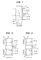
- Fig. 1 is an partially enlarged view of the cylinder 4 and plunger 5.
- the clearance between the cylinder 4 and plunger 5 was not formed over the entire area on the upper and lower portions with the cylindrical groove sandwiched in-between, but was kept to a very small clearance 40a (e.g. 3 ⁇ m) from the compression chamber to the cylindrical groove.
- Clearances 40b and 40c slightly larger than the 40a were formed on the side below the cylindrical groove. Honing is commonly used for precision finishing of a hole such as this bore.
- Honing operation is characterized in that, if there is a cylindrical groove 42 or the like halfway through the hole, distribution of the honing force applied to the honing stone undergoes fluctuation, and honing accuracy is deteriorated without the bore misalignment on the upper and lower parts of the cylindrical groove 42 being not corrected.
- the section from the compression chamber 6 and cylindrical groove 42 where high pressure fuel leakage must be minimized can be specified so that the specified section is precision-finished. This allows the clearance Ga 43 to be reduced, and ensures the smooth sliding operation at the same time.
- a precision straight hole having an inner diameter Da 46 is formed on the straight portion 50 above the cylindrical groove 42 of the bore 40 of the cylinder 4, and the fine tapered portion 51 below the cylindrical groove 42 is provided with a very small taper in the embodiment given in Fig. 2, in such a way as to get the relationship of Da ⁇ Db ⁇ Dc.
- a straight hole 54 and a flared hole 55 connected thereto are formed below the cylindrical groove 42 arrangements are made such that Da ⁇ Db ⁇ Dc.
- the strength with respect to the lateral load may be reduced, as compared to the case where the plunger is guided over the entire area above and below.
- the plunger can be guided by the upper portion 63 and lower portion 64 of the bore 40 of the cylinder 4. This provides a sufficient strength with respect to the lateral load applied to the plunger 5.
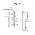
- Numeral 70 denotes a honing stone for finishing the bore 40 of the cylinder 4.
- Numeral 71 indicates the honing stone spindle.
- the lower part feed rate Vc74 is gradually reduced with respect to the axial honing stone feed rate Va72 and axial honing stone feed rate Vb73 of the cylindrical groove 42 in the honing process.
- honing is performed with a very slight elastic deformation occurring to the honing stone, honing stone spindle and its connections. A slight increase in the machining diameter is caused by this elastic deformation when the axial feed rate is reduced.
- this principle is used to control the speed, thereby forming the optimum bore profile as shown in the aforementioned embodiments.
- the same effect can be obtained by changing one or more of the speed of the honing stone 70, number of reciprocating motions and axial feed dwell time.
- the longitudinal section of the cylindrical groove 42 exhibits a form gradually widening toward the bore 40 of the cylinder 4 and the angles 82 and 83 formed at the portion where the cylindrical groove 42 contacts the bore 4 (two flared portions (upper side) and (lower side) 80 and 81) each are 5 degrees or more, but not more than 25 degrees with respect to axial direction of the bore. It has been verified that a minute slack (upper side) 84 and a minute slack (lower side) 85 as the intersections between the portions 80 and 81 of the cylindrical groove 42 and bores 40 are formed in a very smooth shape, when the bore 40 is finished by honing.
- the axial length 61 as an axial width W of the cylindrical groove 42 was configured to ensure that D ⁇ 0.1 or more, but not more than D ⁇ 0.6, with respect to the bore inner diameter D, as shown in Fig. 9. If the axial length W61 as a width is larger, the honing stone 70 becomes unstable temporarily at a position close to the cylindrical groove 42, as shown in Fig. 10. This makes it difficult to correct the axial misalignment. Theoretically, stability can be ensured by use of a axially long honing stone, but in actual practice, it is difficult to achieve a precisely close contact with the bore 40 over the entire length of a long stone. This requires the groove width W to be made shorter. According to experiments, "W" should be kept in the range from D ⁇ 0.1 through D ⁇ 0.6.
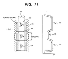
- Fig. 11 shows the method for honing the bore 40 of the cylinder 4.
- the axial feed rate of the honing tool, out of the conditions for honing the bore connected to the cylindrical groove 42 is reduced at the cylindrical groove 42.
- This allows a smooth configuration of the intersection between the cylindrical grooves 42 and bore 40.
- the same effect can be gained by changing one or more of honing stone speed, the number of reciprocating motions and axial dwell time as honing conditions.
- Fig. 12 shows the high pressure fuel pump 1 as an embodiment of the present invention.
- This pump allows reduction of the clearance between the cylinder 4 and plunger 5 without reducing the productivity of the inner diameter of the cylinder 4, and permits smooth sliding. This makes it possible to manufacture a pump characterized by reduced fuel leakage, saved drive energy and improved compression efficiency.
- Fig. 13 shows the configuration of the cylinder 4 and plunger 5 of a prior art pump. Machining is performed to get the same accuracy over the entire range of the bore 40 of the cylinder 4. However, misalignment is likely to occur above and below the cylindrical groove 42. The sliding inhibiting factor 90 interferes with the plunger 5, with the result that smooth sliding cannot be ensured. This requires the clearance Ga 43 to be increased. This is accompanied by increased fuel leakage and deteriorated pump efficiency.
- the present invention proposes a longitudinal section of a bore and the profile of a cylindrical groove to ensure optimization of both pump performances and productivity. It reduces the clearance between the cylinder and plunger with raising the costs by requesting severe parts accuracy, and provides a highly efficient high pressure pump characterized by higher sliding performances than those of the prior art.
- the present invention also provides a method for manufacturing such a pump.
Landscapes
- Engineering & Computer Science (AREA)
- Mechanical Engineering (AREA)
- General Engineering & Computer Science (AREA)
- Chemical & Material Sciences (AREA)
- Combustion & Propulsion (AREA)
- Details Of Reciprocating Pumps (AREA)
- Fuel-Injection Apparatus (AREA)
Abstract
Description
- The present invention relates to a plunger type high pressure pump, particularly to a single cylinder type high pressure fuel pump particularly suited for use in a gasoline direct injection engine.
- In a high pressure pump of a gasoline direct injection engine, the leakage of gasoline from the clearance must be minimized by reducing the clearance of the plunger sliding in the cylinder bore in, for example, several microns or less, in order to compress low viscosity gasoline to a high pressure. To ensure that the gasoline leaking from the clearance escapes to the low pressure side, a cylindrical groove and transverse aperture connected to the low pressure side are commonly provided halfway through the bore.
- In this type of pump according to the prior art, both the bore and plunger have required a high diametric dimensional accuracy and cylindricity over the entire sliding surface in order to ensure a small clearance. To meet such requirements, much cost has been needed for precision finishing and subsequent checking. In mass production, high accuracy requirements could not be met, and sliding failure has occurred. To improve slidability, clearance has to be increased at the sacrifice of pump efficiency in some cases.
- A high pressure pump of this type according to the prior art method is disclosed in the Japanese Application Patents Laid-Open Publication Nos. 2002-130079 and 2001-295727.
Patent Document 1;Japanese Application Patent Laid-Open Publication No. 2002-130079
Patent Document 2;Japanese Application Patent Laid-Open Publication No. 2001-295727. - The aforementioned prior art fails to give consideration to productivity, and has such a problems that costs are increased if high accuracy is to be achieved, and productivity has been neglected. To solve this problem, the clearance has to be increased at the sacrifice of pump performances in order to increase productivity.
- An object of the present invention is to provide a high pressure pump and manufacturing method thereof, wherein the amount of gasoline leaked between the cylinder and plunger is minimized and smooth sliding is ensured, without reducing the productivity of the pump despite improved accuracy.
- This object is achieved by the features of the independent claims. Further embodiments are claimed in the further subclaims.
- To solve the aforementioned problems, the present invention characterized in that the clearance between the bore and plunger can differ according to the specified position of either the plunger or bore.
- Further, the present invention can be characterized in that Ga ≤ Gb < Gc or Ga < Gb ≤ Gc, wherein Ga denotes a clearing between the bore on the portion from the compression chamber to the cylindrical groove and the plunger; Gb a clearance closer to the cylindrical groove, out of the clearances between the bore from the cylindrical groove to the drive source side and the plunger; and Gc a clearance closer to the drive source side, out of the clearances between the bore from the cylindrical groove to the drive source side and the plunger.
- The present invention is further characterized in that the longitudinal section of the cylindrical groove can exhibit a form gradually widening toward the bore of the cylinder, and/or the angle formed at the portion where the cylindrical groove contacts the bore can be 5 degrees or more, but can be not more than 25 degrees with respect to axial direction of the bore.
- The present invention will hereinafter be described in detail by way of example with reference to the accompanying drawings.
- Fig. 1 is a cross sectional view representing the cylinder and plunger of a high pressure pump as an embodiment of the present invention;
- Fig. 2 is a cross sectional view representing the cylinder of a high pressure pump as an embodiment of the present invention;
- Fig. 3 is a cross sectional view representing the cylinder of a high pressure pump as an embodiment of the present invention;
- Fig. 4 is a cross sectional view representing the cylinder of a high pressure pump as an embodiment of the present invention;
- Fig. 5 is a cross sectional view representing the cylinder of a high pressure pump as an embodiment of the present invention;
- Fig. 6 is a cross sectional view representing the cylinder and plunger of a high pressure pump as an embodiment of the present invention;
- Fig. 7 is a cross sectional view representing the honing process of the cylinder of a high pressure pump as an embodiment of the present invention;
- Fig. 8 is a cross sectional view representing the cylinder of a high pressure pump as an embodiment of the present invention;
- Fig. 9 is a cross sectional view representing the enlarged view of the cylindrical groove of the cylinder given in Fig. 8;
- Fig. 10 is a cross sectional view representing the status of honing a cylinder according to the prior art;
- Fig. 11 is a cross sectional view representing the honing process of the cylinder of a high pressure pump as an embodiment of the present invention;
- Fig. 12 is a cross sectional view representing a high pressure pump as an embodiment of the present invention; and
- Fig. 13 is a cross sectional view representing the cylinder and plunger of a high pressure pump according to the prior art.
-
- The following are reference numerals used in the Drawing:
- 1 denotes high pressure pump, 2 housing, 3 drive
source, 4 cylinder, 5 plunger, 6 compression chamber,
7 reciprocating motion, 40 bore, 41 transverse
aperture, 42 cylindrical groove, 43 clearance ga, 44
clearance gb, 45 clearance gc ,46 inner diameter da,
47 inner diameter db, 48 inner diameter dc, 50, 52,
54, 54 straight section, 51 fine tapered portion,
53, 55 (minute) flare hole, 60
axial length 1a, 61 axial length w, 62 axial length lbc, 63 contact point (upper portion), 64 contact point (lower portion), 70 honing stone, 71. honing stone spindle, 72 feed rate va, 73 feed rate vb, 74 fed rate vc, 80 flared portion (upper side), 81 flared portion (lower side), 82 angle (upper side), 83 angle (lower side), 84 minute slack (upper side), 85 minute slack (lower side), 90 sliding inhibiting factor, 91 sealing member, 501 one end of plunger (compression chamber side), and 502 one end of plunger (drive source side). -
- One of the embodiments of the present invention is characterized in that Ga ≤ Gb < Gc or Ga < Gb ≤ Gc, wherein Ga denotes a clearing between the bore and plunger on the portion leading to the cylindrical groove from the compression chamber of a high pressure pump where a transverse aperture is connected with the bore through a cylindrical groove provided halfway through the bore of the cylinder; Gb a clearance closer to the cylindrical groove, out of the clearances between the bore from the cylindrical groove to the drive source side and the plunger; and Gc a clearance closer to the drive source side, out of the clearances between the bore from the cylindrical groove to the drive source side and the plunger.
- To achieve this clearance relationship using the machined profile on the cylinder bore side, arrangements are made to get Da ≤ Db < Dc or Da < Db ≤ Dc wherein:
- Da denotes an inner diameter of the bore on the portion from the compression chamber of the top portion of the cylinder to the cylindrical groove;
- Db an inner diameter closer to the cylindrical groove, out of the inner diameters of the bore from the cylindrical groove to the drive source side; and
- Dc an inner diameter closer to the drive source side, out of the inner diameters of the bores of the cylinder from the cylindrical groove to the drive source side.
-
- To minimize the leakage of gasoline and to secure the sliding length (axial length) thereby providing strength to the lateral load, arrangements are made to ensure that Gc ≤ ((La + W + Lbc)/La) × Ga or Dc ≤ ((La + W + Lbc)/La) × Da; wherein La is the width of the cylinder bore in the axial direction on the portion from the compression chamber to the cylindrical groove; W the width of the cylindrical groove in the axial direction; and Lbc the width of the portion from the cylindrical groove to the drive source side.
- A method for manufacturing such a pump is characterized in that, with respect to the conditions for honing the bore on the portion from the compression chamber of a pump cylinder to a cylindrical groove, the conditions for honing the bore on the portion from the cylindrical groove to the drive source side are determined by changing one or more of the axial feed rate, honing stone speed, number of reciprocating motions and axial feed dwell time of the honing tool.
- In a high pressure pump where a transverse aperture is connected with the bore through a cylindrical groove provided halfway through the bore of the cylinder, the longitudinal section of the cylindrical groove exhibits a form gradually widening toward the bore of the cylinder, and the angle formed at the portion where the cylindrical groove contacts the bore is 5 degrees or more, but not more than 25 degrees with respect to axial direction of the bore.
- Further, in order to reduce the displacement of the center shafts of the bores on the top (compression chamber side) and bottom (drive source side) of the cylindrical groove, the width W of the cylindrical groove in the axial direction is D × 0.1 or more, but not more than D × 0.6 with respect to the inner diameter D of the bore.
- A method for manufacturing such a pump is characterized in that, with respect to the conditions for honing the bore on the portion from the compression chamber of a cylinder to a cylindrical groove and the conditions for honing the bore on the portion from the cylindrical groove to the drive source side, the conditions for honing the bore on the portion connected to the cylindrical groove determined by changing one or more of the axial feed rate, honing stone speed, number of reciprocating motions and axial feed dwell time of the honing tool.
- The following describes the embodiments of the present invention:
- Referring to Fig. 12, the following describes the configuration of a high pressure pump. A single cylinder high
pressure fuel pump 1 for gasoline direct injection engine shown in Fig. 12 contains acylinder 4 and aplunger 5 performing a reciprocating motion between thecylinder 4 and bore 40, in thehousing 2. Oneend 501 of theplunger 5 is connected to acompression chamber 6, and theother end 502 of the plunger is connected to thedrive source 3 as a drive cam for reciprocating motion through a tappet member. Acylindrical groove 42 and atransverse aperture 41 connected thereto are formed close to the center of thecylinder 4. When theplunger 5 moves in the upward direction in the figure, the gasoline inside thecompression chamber 6 is compressed. If theplunger 5 moves in the downward direction in the figure, the gasoline is sucked into thecompression chamber 6. Loss in the pump efficiency caused by reciprocating motion of theplunger 5 includes the leakage of gasoline from the space between thebore 40 of thecylinder 4 andplunger 5, namely the clearance. If a excessive amount of gasoline leaks, the delivery rate of thepump 1 will be reduced, and combustion pressure fails to rise to a specified level, in extreme cases. Especially when gasoline is used as a fluid to be compressed, this problem is conspicuous since its has an extremely low viscosity. To solve the problem, the clearance between thecylinder 4 andplunger 5 must be kept to a very small level of several microns. - Since gasoline is poor in lubricity, the
cylinder 4 and/orplunger 5 may be worn due to thereciprocating motion 7 of theplunger 5. To avoid such a problem and to make an effective use of energy from the drive source, smooth sliding of theplunger 5 must be ensured. This presents a problem when reducing the clearance dimensions. Further, this pump contains atransverse aperture 41 and acylindrical groove 42 connected to the low pressure chamber in order to return the fuel leaking from theclearance 43 to the low pressure side, in such a way that the pressure of the fuel leaking from thecompression chamber 6 is not applied to a sealing member 91 directly. - Fig. 1 is an partially enlarged view of the
cylinder 4 andplunger 5. In the present embodiment, the clearance between thecylinder 4 andplunger 5 was not formed over the entire area on the upper and lower portions with the cylindrical groove sandwiched in-between, but was kept to a verysmall clearance 40a (e.g. 3 µm) from the compression chamber to the cylindrical groove.Clearances cylindrical groove 42 or the like halfway through the hole, distribution of the honing force applied to the honing stone undergoes fluctuation, and honing accuracy is deteriorated without the bore misalignment on the upper and lower parts of thecylindrical groove 42 being not corrected. In the present embodiment, the section from thecompression chamber 6 andcylindrical groove 42 where high pressure fuel leakage must be minimized can be specified so that the specified section is precision-finished. This allows theclearance Ga 43 to be reduced, and ensures the smooth sliding operation at the same time. - The following describes another embodiment with reference to Fig. 2 through Fig. 5: To get the same effect as that in the aforementioned embodiment, a precision straight hole having an
inner diameter Da 46 is formed on thestraight portion 50 above thecylindrical groove 42 of thebore 40 of thecylinder 4, and the fine taperedportion 51 below thecylindrical groove 42 is provided with a very small taper in the embodiment given in Fig. 2, in such a way as to get the relationship of Da < Db < Dc. - In the embodiment of Fig 3, a straight hole having an inner diameter slightly larger than the Da above the
cylindrical groove 42 is formed below thecylindrical groove 42. To be more specific, arrangements are made such that Da < Db = Dc. - In the embodiment of Fig. 4, a fine flared hole is formed below the
cylindrical groove 42 and arrangements are made such that Da = Db < Dc. - In the embodiment of Fig. 5, a
straight hole 54 and a flaredhole 55 connected thereto are formed below thecylindrical groove 42 arrangements are made such that Da < Db < Dc. - The same effect as that in
EMBODIMENT 1 is obtained. - A further embodiment will be described with reference to Fig. 6: Arrangements are made in such a way that Gc ≤ ((La + W + Lbc)/La) × Ga or Dc ≤ ((La + W + Lbc)/La) × Da, based on the
axial length La 60 as an axial width of the portion from thecompression chamber 6 to thecylindrical groove 42, of thebore 40 of thecylinder 4, the axial length W61 as an axial width of thecylindrical groove 42, andaxial length Lbc 62 as an width on the portion from thecylindrical groove 42 to the drive source side. As shown in the aforementioned embodiment, when the minimum clearance is restricted only to the portion above the cylindrical groove, the strength with respect to the lateral load may be reduced, as compared to the case where the plunger is guided over the entire area above and below. In this embodiment, even when consideration is given to the maximum inclination of the plunger during sliding operation, the plunger can be guided by theupper portion 63 andlower portion 64 of thebore 40 of thecylinder 4. This provides a sufficient strength with respect to the lateral load applied to theplunger 5. - The following describes a further embodiment of the method for forming a bore of the cylinder mentioned in the aforementioned embodiment, with reference to Fig. 7:
Numeral 70 denotes a honing stone for finishing thebore 40 of thecylinder 4.Numeral 71 indicates the honing stone spindle. In this embodiment, the lower part feed rate Vc74 is gradually reduced with respect to the axial honing stone feed rate Va72 and axial honing stone feed rate Vb73 of thecylindrical groove 42 in the honing process. In the honing operation, honing is performed with a very slight elastic deformation occurring to the honing stone, honing stone spindle and its connections. A slight increase in the machining diameter is caused by this elastic deformation when the axial feed rate is reduced. In this embodiment, this principle is used to control the speed, thereby forming the optimum bore profile as shown in the aforementioned embodiments. - The same effect can be obtained by changing one or more of the speed of the honing
stone 70, number of reciprocating motions and axial feed dwell time. - The following describes a still further embodiment with reference to Fig. 8: In this embodiment, the longitudinal section of the
cylindrical groove 42 exhibits a form gradually widening toward thebore 40 of thecylinder 4 and theangles cylindrical groove 42 contacts the bore 4 (two flared portions (upper side) and (lower side) 80 and 81) each are 5 degrees or more, but not more than 25 degrees with respect to axial direction of the bore. It has been verified that a minute slack (upper side) 84 and a minute slack (lower side) 85 as the intersections between theportions cylindrical groove 42 and bores 40 are formed in a very smooth shape, when thebore 40 is finished by honing. This is because generation of burrs is reduced in the range from 5 to 25 degrees during the honing operation wherein these burrs are caused by very slightly plastic deformation of the top surface layer of thecylinder 4, and at the same time, a smooth radius is formed by the aforementioned slight plastic deformation on the side of the honing stone; namely, this is caused by a synergistic effect of these two factors. Thus, smooth sliding is obtained even when theclearance Ga 43 between thecylinder 4 andplunger 5 is reduced by the minute slack (upper side) 84 and minute slack (lower side) 85 forming this smooth radius. - In addition to the aforementioned embodiments, the
axial length 61 as an axial width W of thecylindrical groove 42 was configured to ensure that D × 0.1 or more, but not more than D × 0.6, with respect to the bore inner diameter D, as shown in Fig. 9. If the axial length W61 as a width is larger, the honingstone 70 becomes unstable temporarily at a position close to thecylindrical groove 42, as shown in Fig. 10. This makes it difficult to correct the axial misalignment. Theoretically, stability can be ensured by use of a axially long honing stone, but in actual practice, it is difficult to achieve a precisely close contact with thebore 40 over the entire length of a long stone. This requires the groove width W to be made shorter. According to experiments, "W" should be kept in the range from D × 0.1 through D × 0.6. - Fig. 11 shows the method for honing the
bore 40 of thecylinder 4. In this example, with respect to the conditions for honing the bore on the portion from thecompression chamber 6 of thecylinder 4 to thecylindrical groove 42 and conditions for honing the bore from thecylindrical groove 42 to the drive source side, the axial feed rate of the honing tool, out of the conditions for honing the bore connected to thecylindrical groove 42, is reduced at thecylindrical groove 42. This allows a smooth configuration of the intersection between thecylindrical grooves 42 and bore 40. Further, the same effect can be gained by changing one or more of honing stone speed, the number of reciprocating motions and axial dwell time as honing conditions. - Fig. 12 shows the high
pressure fuel pump 1 as an embodiment of the present invention. This pump allows reduction of the clearance between thecylinder 4 andplunger 5 without reducing the productivity of the inner diameter of thecylinder 4, and permits smooth sliding. This makes it possible to manufacture a pump characterized by reduced fuel leakage, saved drive energy and improved compression efficiency. - Fig. 13 shows the configuration of the
cylinder 4 andplunger 5 of a prior art pump. Machining is performed to get the same accuracy over the entire range of thebore 40 of thecylinder 4. However, misalignment is likely to occur above and below thecylindrical groove 42. The sliding inhibitingfactor 90 interferes with theplunger 5, with the result that smooth sliding cannot be ensured. This requires theclearance Ga 43 to be increased. This is accompanied by increased fuel leakage and deteriorated pump efficiency. - The present invention proposes a longitudinal section of a bore and the profile of a cylindrical groove to ensure optimization of both pump performances and productivity. It reduces the clearance between the cylinder and plunger with raising the costs by requesting severe parts accuracy, and provides a highly efficient high pressure pump characterized by higher sliding performances than those of the prior art. The present invention also provides a method for manufacturing such a pump.
Claims (11)
- A high pressure pump (1) comprising a housing (2) and a cylinder (4) in said housing (2) wherein a shaft-like plunger (5) makes a reciprocating motion (7) in the bore (40) formed in said cylinder (4) to compress a fluid; said high pressure pump (1) characterized in that:one end (501) of said plunger (5) is connected to a compression chamber (6) for compressing the fluid, while the other end (502) is connected to a reciprocating motion (7) drive source (3) through a member; wherein a transverse aperture (41) is connected with the bore (40) through a cylindrical groove (42) provided halfway through the cross section of the bore (40) of said cylinder (4) in the axial direction; and the clearance (43, 44, 45) between said bore (40) and said plunger (5) varies depending on the specified position of either said plunger (5) or bore (40).
- The high pressure pump (1) according to claim 1 characterized in that Ga ≤ Gb < Gc or
Ga < Gb ≤ Gc, wherein:Ga denotes a clearing (43) between the bore (40) on the portion from said compression chamber (6) to said cylindrical groove (42) and said plunger (5);Gb a clearance (44) closer to the cylindrical groove (42), out of the clearances (43, 44, 45) between the bore (40) from said cylindrical groove (42) to the drive source side and said plunger (5); andGc a clearance (45) closer to the drive source side, out of the clearances (43, 44, 45) between the bore (40) from said cylindrical groove (42) to the drive source side and said plunger (5). - The high pressure pump (1) according to claim 1 or 2 characterized in that Da ≤ Db < Dc or Da < Db ≤ Dc wherein:Da denotes an inner diameter (46) of the bore (40) on the portion from said compression chamber (6) to said cylindrical groove (42);Db an inner diameter (47) closer to the cylindrical groove (42), out of the inner diameters (46, 47, 48) of the bore (40) from said cylindrical groove (42) to the drive source side; andDc an inner diameter (48) closer to the drive source side, out of the inner diameters (46, 47, 48) of the bores (40) of the cylinder (4) from said cylindrical groove (42) to the drive source side.
- The high pressure pump (1) according to at least one of the claims 1 to 3 characterized in thatLa is the width (60) of said cylinder bore (40) in the axial direction on the portion from the compression chamber (6) to the cylindrical groove (42);W the width (61) of said cylindrical groove (42) in the axial direction; andLbc the width (62) of the portion from the cylindrical groove (42) to the drive source side.
- The high pressure pump (1) according to at least one of the claims 1 to 4 characterized in thatLa is the width (60) of said cylinder bore in the axial direction on the portion from the compression chamber (6) to the cylindrical groove (42);W the width (61) of said cylindrical groove (42) in the axial direction; andLbc the width (62) of the portion from the cylindrical groove (42) to the drive source side.
- A high pressure pump (1) comprising a housing (2) and a cylinder (4) in said housing (2) wherein a shaft-like plunger (5) makes a reciprocating motion (7) in the bore (40) formed in said cylinder (4) to compress a fluid; said high pressure pump (1) characterized in that one end (501) of said plunger (5) is connected to a compression chamber (6), while the other end (502) is connected to a reciprocating motion (7) drive source (3) through a member; wherein a transverse aperture (41) is connected with the bore (40) through a cylindrical groove (42) provided halfway through the cross section of the bore (40) of said cylindrical groove (42) in the axial direction; the longitudinal section of said cylindrical groove (42) exhibits a form gradually widening toward the bore (40) of said cylinder (4), and the angle (82, 83) formed at the portion where said cylindrical groove (42) contacts the bore (40) is 5 degrees or more, but not more than 25 degrees with respect to axial direction of the bore (40).
- The high pressure pump (1) according to claim 6 characterized in that the width W (61) of said cylindrical groove (42) in the axial direction is D x 0.1 or more, but not more than D x 0.6 with respect to the inner diameter D of the bore (40).
- A high pressure pump manufacturing method characterized in that, with respect to the conditions for honing the bore (40) on the portion from the compression chamber (6) of a pump cylinder (4) to a cylindrical groove (42), the conditions for honing the bore (40) on the portion from said cylindrical groove (42) to the drive source side is determined by changing one or more of the axial feed rate (va, vb, vc), honing stone (70) speed, number of reciprocating motions (7) and axial feed dwell time of said honing tool.
- The high pressure pump manufacturing method according to claim 8 characterized in that the conditions of changing one or more of the axial feed rate (va, vb, vc), honing stone (70) speed, number of reciprocating motions (7) and axial feed dwell time of said honing tool are the conditions for honing the bore (40) on the portion connected to said cylindrical groove (42), with respect to said conditions for honing the bore (40) on the portion from the compression chamber (6) of the pump cylinder (4) to the cylindrical groove (42) and said conditions for honing the bore (40) on the portion from said cylindrical groove (42) to the drive source side.
- The high pressure pump manufacturing method according to claim 8 or 9, said pump characterized in that Ga ≤ Gb < Gc or Ga < Gb ≤ Gc, wherein:Ga denotes a clearing (43) between the bore (40) on the portion from said compression chamber (6) to said cylindrical groove (42) and said plunger (5);Gb a clearance (44) closer to the cylindrical groove (42), out of the clearances (43, 44, 45) between the bore (40) from said cylindrical groove (42) to the drive source side and said plunger (5); andGc a clearance (45) closer to the drive source side, out of the clearances (43, 44, 45) between the bore (40) from said cylindrical groove (42) to the drive source side and said plunger (5).
- The high pressure pump manufacturing method according to at least one of the claims 8 to 10, said pump (1) characterized in that the longitudinal section of said cylindrical groove (42) exhibits a form gradually widening toward the bore (40) of said cylinder (4), and the angle (82, 83) formed at the portion where said cylindrical groove (42) contacts the bore (40) is 5 degrees or more, but not more than 25 degrees with respect to axial direction of the bore (40).
Applications Claiming Priority (2)
| Application Number | Priority Date | Filing Date | Title |
|---|---|---|---|
| JP2003069072A JP3979313B2 (en) | 2003-03-14 | 2003-03-14 | High pressure pump |
| JP2003069072 | 2003-03-14 |
Publications (2)
| Publication Number | Publication Date |
|---|---|
| EP1457665A1 true EP1457665A1 (en) | 2004-09-15 |
| EP1457665B1 EP1457665B1 (en) | 2006-07-05 |
Family
ID=32767970
Family Applications (1)
| Application Number | Title | Priority Date | Filing Date |
|---|---|---|---|
| EP04002714A Expired - Lifetime EP1457665B1 (en) | 2003-03-14 | 2004-02-06 | High pressure pump and manufacturing process thereof |
Country Status (4)
| Country | Link |
|---|---|
| US (1) | US7478582B2 (en) |
| EP (1) | EP1457665B1 (en) |
| JP (1) | JP3979313B2 (en) |
| DE (1) | DE602004001409T2 (en) |
Cited By (4)
| Publication number | Priority date | Publication date | Assignee | Title |
|---|---|---|---|---|
| WO2011088954A1 (en) * | 2010-01-21 | 2011-07-28 | Robert Bosch Gmbh | High-pressure pump |
| CN101294532B (en) * | 2007-04-27 | 2012-10-10 | 曼柴油机欧洲股份公司 | Fuel pump |
| WO2015120930A1 (en) * | 2014-02-13 | 2015-08-20 | Delphi International Operations Luxembourg S.À R.L. | Fuel pump |
| CN107035681A (en) * | 2017-06-22 | 2017-08-11 | 杭州力龙液压有限公司 | Plunger, plunger pump and hydraulic device |
Families Citing this family (12)
| Publication number | Priority date | Publication date | Assignee | Title |
|---|---|---|---|---|
| US20070009367A1 (en) * | 2005-04-21 | 2007-01-11 | Kmt Waterjet Systems, Inc. | Close fit cylinder and plunger |
| JP4386030B2 (en) * | 2005-12-02 | 2009-12-16 | トヨタ自動車株式会社 | High pressure pump |
| JP2009091955A (en) * | 2007-10-05 | 2009-04-30 | Yanmar Co Ltd | Supply pump |
| KR101034022B1 (en) * | 2008-09-25 | 2011-05-11 | 기아자동차주식회사 | Fuel Pump Lubricator Driven By Cam |
| JP5071401B2 (en) * | 2009-02-05 | 2012-11-14 | 株式会社デンソー | Fuel supply device |
| EP2320084B1 (en) * | 2009-11-06 | 2012-09-12 | Delphi Technologies Holding S.à.r.l. | Housing with intersecting passages for high pressure fluid applications |
| JP5840865B2 (en) * | 2011-05-19 | 2016-01-06 | 株式会社ニッキ | Fuel pump |
| CN102536565A (en) * | 2011-12-30 | 2012-07-04 | 成都威特电喷有限责任公司 | Plunger and barrel assembly capable of eliminating hydraulic clamping force of electrically-controlled high-pressure fuel pump plunger and barrel assembly |
| GB201516152D0 (en) * | 2015-09-11 | 2015-10-28 | Delphi Int Operations Lux Srl | Fuel pump housing |
| GB2553484A (en) * | 2016-04-26 | 2018-03-14 | Delphi Int Operations Luxembourg Sarl | High pressure diesel pump |
| DE102019130684A1 (en) * | 2019-11-14 | 2021-05-20 | Man Energy Solutions Se | Piston pump |
| JP7706280B2 (en) * | 2021-07-06 | 2025-07-11 | 三菱重工エンジン&ターボチャージャ株式会社 | Fuel Pump |
Citations (3)
| Publication number | Priority date | Publication date | Assignee | Title |
|---|---|---|---|---|
| US5125807A (en) * | 1989-04-04 | 1992-06-30 | Kloeckner-Humboldt-Deutz Ag | Fuel injection device |
| EP0537911A1 (en) * | 1991-10-12 | 1993-04-21 | Lucas Industries Public Limited Company | Fuel pump |
| EP1277951A2 (en) * | 2001-07-19 | 2003-01-22 | Hitachi, Ltd. | High pressure fuel pump for internal combustion engine |
Family Cites Families (3)
| Publication number | Priority date | Publication date | Assignee | Title |
|---|---|---|---|---|
| US4776260A (en) * | 1980-11-07 | 1988-10-11 | Vincze Alexander L | Constant pressure pump |
| JP3851056B2 (en) | 2000-04-18 | 2006-11-29 | トヨタ自動車株式会社 | High pressure pump |
| JP2002130079A (en) | 2000-10-23 | 2002-05-09 | Bosch Automotive Systems Corp | Pump chamber pressure controller in high-pressure pump |
-
2003
- 2003-03-14 JP JP2003069072A patent/JP3979313B2/en not_active Expired - Fee Related
-
2004
- 2004-02-06 DE DE602004001409T patent/DE602004001409T2/en not_active Expired - Lifetime
- 2004-02-06 EP EP04002714A patent/EP1457665B1/en not_active Expired - Lifetime
- 2004-02-20 US US10/781,631 patent/US7478582B2/en not_active Expired - Fee Related
Patent Citations (3)
| Publication number | Priority date | Publication date | Assignee | Title |
|---|---|---|---|---|
| US5125807A (en) * | 1989-04-04 | 1992-06-30 | Kloeckner-Humboldt-Deutz Ag | Fuel injection device |
| EP0537911A1 (en) * | 1991-10-12 | 1993-04-21 | Lucas Industries Public Limited Company | Fuel pump |
| EP1277951A2 (en) * | 2001-07-19 | 2003-01-22 | Hitachi, Ltd. | High pressure fuel pump for internal combustion engine |
Cited By (6)
| Publication number | Priority date | Publication date | Assignee | Title |
|---|---|---|---|---|
| CN101294532B (en) * | 2007-04-27 | 2012-10-10 | 曼柴油机欧洲股份公司 | Fuel pump |
| WO2011088954A1 (en) * | 2010-01-21 | 2011-07-28 | Robert Bosch Gmbh | High-pressure pump |
| CN102713241A (en) * | 2010-01-21 | 2012-10-03 | 罗伯特·博世有限公司 | High-pressure pump |
| WO2015120930A1 (en) * | 2014-02-13 | 2015-08-20 | Delphi International Operations Luxembourg S.À R.L. | Fuel pump |
| CN106232980A (en) * | 2014-02-13 | 2016-12-14 | 德尔福国际业务卢森堡公司 | Petrolift |
| CN107035681A (en) * | 2017-06-22 | 2017-08-11 | 杭州力龙液压有限公司 | Plunger, plunger pump and hydraulic device |
Also Published As
| Publication number | Publication date |
|---|---|
| EP1457665B1 (en) | 2006-07-05 |
| JP2004278373A (en) | 2004-10-07 |
| JP3979313B2 (en) | 2007-09-19 |
| US7478582B2 (en) | 2009-01-20 |
| DE602004001409T2 (en) | 2007-02-08 |
| DE602004001409D1 (en) | 2006-08-17 |
| US20040179963A1 (en) | 2004-09-16 |
Similar Documents
| Publication | Publication Date | Title |
|---|---|---|
| US7478582B2 (en) | High pressure pump and manufacturing process thereof | |
| EP2129869B1 (en) | Low leakage plunger assembly for a high pressure fluid system | |
| US5775203A (en) | High pressure fuel pump assembly | |
| EP3502496B1 (en) | Half thrust bearing | |
| US10119613B2 (en) | Wrist pin and method of reducing wear between members thereof, connecting rod, piston and methods of constructing same | |
| JP2002168158A (en) | High-pressure fuel accumulator for fuel injection system for internal combustion engines | |
| US5107807A (en) | Piston for internal combustion engine | |
| US20040091377A1 (en) | High-pressure fuel pump | |
| US6364641B2 (en) | Fuel injection pump | |
| CN1668842A (en) | Fuel-injection valve for internal combustion engines | |
| US10961947B2 (en) | Cylinder liner | |
| EP1015766B1 (en) | Coupling for high pressure fluid pump assembly | |
| US6729286B2 (en) | Fuel supply apparatus for engine | |
| US7448362B2 (en) | Conduit arrangement in a control valve module for a fuel injector assembly | |
| CN103867711B (en) | Piston-cylinder units | |
| JP2004019703A (en) | Gas bearing | |
| EP2642093B1 (en) | Rocker arm shaft with improved abrasion resistance and rocker arm shaft/bush assembly comprising same | |
| JP3850928B2 (en) | Fuel injection pump for internal combustion engines | |
| US20200200133A1 (en) | Camshaft for a pump, in particular a high pressure fuel pump, and pump having a camshaft | |
| CN113302394A (en) | High-pressure fuel pump | |
| CN217300748U (en) | Common rail pump high pressure chamber fuel sealing device | |
| JP2024098762A (en) | Fuel injection pump | |
| GB2276921A (en) | Fuel injection pump for an internal combustion engine |
Legal Events
| Date | Code | Title | Description |
|---|---|---|---|
| PUAI | Public reference made under article 153(3) epc to a published international application that has entered the european phase |
Free format text: ORIGINAL CODE: 0009012 |
|
| AK | Designated contracting states |
Kind code of ref document: A1 Designated state(s): AT BE BG CH CY CZ DE DK EE ES FI FR GB GR HU IE IT LI LU MC NL PT RO SE SI SK TR |
|
| AX | Request for extension of the european patent |
Extension state: AL LT LV MK |
|
| RIN1 | Information on inventor provided before grant (corrected) |
Inventor name: KAJIYAMA, YASUHIRO Inventor name: YAMADA, HIROYUKI Inventor name: AIKAWA, SHIGEO Inventor name: KUBOTA, EIICHI Inventor name: YOSHIDA, MICHIO |
|
| 17P | Request for examination filed |
Effective date: 20050106 |
|
| AKX | Designation fees paid |
Designated state(s): DE |
|
| 17Q | First examination report despatched |
Effective date: 20050503 |
|
| GRAP | Despatch of communication of intention to grant a patent |
Free format text: ORIGINAL CODE: EPIDOSNIGR1 |
|
| GRAS | Grant fee paid |
Free format text: ORIGINAL CODE: EPIDOSNIGR3 |
|
| GRAA | (expected) grant |
Free format text: ORIGINAL CODE: 0009210 |
|
| RIN1 | Information on inventor provided before grant (corrected) |
Inventor name: YOSHIDA, MICHIO,H Inventor name: YAMADA, HIROYUKI,H Inventor name: KAJIYAMA, YASUHIRO,H Inventor name: AIKAWA, SHIGEO,H Inventor name: KUBOTA, EIICHI, H |
|
| AK | Designated contracting states |
Kind code of ref document: B1 Designated state(s): DE |
|
| RAP1 | Party data changed (applicant data changed or rights of an application transferred) |
Owner name: HITACHI, LTD. |
|
| RIN1 | Information on inventor provided before grant (corrected) |
Inventor name: YOSHIDA, MICHIO, HITACHI LTD., INT.PROP.GROUP, Inventor name: AIKAWA, SHIGEO, HITACHI LTD., INT.PROP.GROUP, Inventor name: KUBOTA, EIICHI, HITACHI LTD., INT.PROP.GROUP, Inventor name: YAMADA, HIROYUKI, HITACHI LTD., INT.PROP.GROUP, Inventor name: KAJIYAMA, YASUHIRO, HITACHI LTD., INT.PROP.GROUP, |
|
| REF | Corresponds to: |
Ref document number: 602004001409 Country of ref document: DE Date of ref document: 20060817 Kind code of ref document: P |
|
| PLBE | No opposition filed within time limit |
Free format text: ORIGINAL CODE: 0009261 |
|
| STAA | Information on the status of an ep patent application or granted ep patent |
Free format text: STATUS: NO OPPOSITION FILED WITHIN TIME LIMIT |
|
| 26N | No opposition filed |
Effective date: 20070410 |
|
| PGFP | Annual fee paid to national office [announced via postgrant information from national office to epo] |
Ref country code: DE Payment date: 20150203 Year of fee payment: 12 |
|
| REG | Reference to a national code |
Ref country code: DE Ref legal event code: R119 Ref document number: 602004001409 Country of ref document: DE |
|
| PG25 | Lapsed in a contracting state [announced via postgrant information from national office to epo] |
Ref country code: DE Free format text: LAPSE BECAUSE OF NON-PAYMENT OF DUE FEES Effective date: 20160901 |