EP1457659A2 - Apparatus and method for mounting a cascade support ring to a thrust reverser - Google Patents
Apparatus and method for mounting a cascade support ring to a thrust reverser Download PDFInfo
- Publication number
- EP1457659A2 EP1457659A2 EP04075467A EP04075467A EP1457659A2 EP 1457659 A2 EP1457659 A2 EP 1457659A2 EP 04075467 A EP04075467 A EP 04075467A EP 04075467 A EP04075467 A EP 04075467A EP 1457659 A2 EP1457659 A2 EP 1457659A2
- Authority
- EP
- European Patent Office
- Prior art keywords
- thrust reverser
- support ring
- track
- fitting
- cascade support
- Prior art date
- Legal status (The legal status is an assumption and is not a legal conclusion. Google has not performed a legal analysis and makes no representation as to the accuracy of the status listed.)
- Granted
Links
Images


Classifications
-
- F—MECHANICAL ENGINEERING; LIGHTING; HEATING; WEAPONS; BLASTING
- F02—COMBUSTION ENGINES; HOT-GAS OR COMBUSTION-PRODUCT ENGINE PLANTS
- F02K—JET-PROPULSION PLANTS
- F02K1/00—Plants characterised by the form or arrangement of the jet pipe or nozzle; Jet pipes or nozzles peculiar thereto
- F02K1/78—Other construction of jet pipes
- F02K1/80—Couplings or connections
-
- F—MECHANICAL ENGINEERING; LIGHTING; HEATING; WEAPONS; BLASTING
- F02—COMBUSTION ENGINES; HOT-GAS OR COMBUSTION-PRODUCT ENGINE PLANTS
- F02K—JET-PROPULSION PLANTS
- F02K1/00—Plants characterised by the form or arrangement of the jet pipe or nozzle; Jet pipes or nozzles peculiar thereto
- F02K1/54—Nozzles having means for reversing jet thrust
- F02K1/64—Reversing fan flow
- F02K1/70—Reversing fan flow using thrust reverser flaps or doors mounted on the fan housing
- F02K1/72—Reversing fan flow using thrust reverser flaps or doors mounted on the fan housing the aft end of the fan housing being movable to uncover openings in the fan housing for the reversed flow
-
- F—MECHANICAL ENGINEERING; LIGHTING; HEATING; WEAPONS; BLASTING
- F05—INDEXING SCHEMES RELATING TO ENGINES OR PUMPS IN VARIOUS SUBCLASSES OF CLASSES F01-F04
- F05D—INDEXING SCHEME FOR ASPECTS RELATING TO NON-POSITIVE-DISPLACEMENT MACHINES OR ENGINES, GAS-TURBINES OR JET-PROPULSION PLANTS
- F05D2230/00—Manufacture
- F05D2230/60—Assembly methods
-
- Y—GENERAL TAGGING OF NEW TECHNOLOGICAL DEVELOPMENTS; GENERAL TAGGING OF CROSS-SECTIONAL TECHNOLOGIES SPANNING OVER SEVERAL SECTIONS OF THE IPC; TECHNICAL SUBJECTS COVERED BY FORMER USPC CROSS-REFERENCE ART COLLECTIONS [XRACs] AND DIGESTS
- Y02—TECHNOLOGIES OR APPLICATIONS FOR MITIGATION OR ADAPTATION AGAINST CLIMATE CHANGE
- Y02T—CLIMATE CHANGE MITIGATION TECHNOLOGIES RELATED TO TRANSPORTATION
- Y02T50/00—Aeronautics or air transport
- Y02T50/60—Efficient propulsion technologies, e.g. for aircraft
Definitions
- the present invention relates generally to thrust reversers for jet engines and more particularly to apparatus and methods for mounting cascade support rings to thrust reversers.
- Thrust reversers are commonly used to reverse the direction of thrust generated by an aircraft jet engine so that the same may be used as a deceleration force for the aircraft.
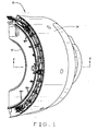
- many existing thrust reversers 10 include a fixed structure 12, sleeve 14 that is translatable relative to the fixed structure 12, and a plurality of cascades 16 each of which includes a plurality of vanes 18.
- the fixed structure 12 of the thrust reverser 10 includes a torque box 20, a hinge beam 22, a latch beam 24, and a cascade support ring 26 mounted to each cascade 16.
- cascades 16 are commonly bolted to the thrust reverser 10. As shown in Figures 2 and 4, nut and bolt assemblies 28 are used to attach the fore end portion 30 of each cascade 16 to the torque box 20. Similarly, nut and bolt assemblies 32 are used to attach the aft end portion 34 of each cascade 16 to its corresponding cascade support ring 26.
- the upper and lower end portions 36 and 38 of the cascade support rings 26 are, in turn, bolted to the respective hinge and latch beams 22 and 24, thus forming relatively fixed joints 25 therebetween. More specifically, nut and bolt assemblies 40 are used to attach the end portions 36 and 38 of the cascade support rings 26 to fittings 42, which are integral to the hinge and latch beams 22, 24.
- a drill cage or jig is typically used to aid in accurate drilling of the torque box 20 and the cascade support rings 26 with the bolt holes, which are used for attachment of the cascades 16 to the torque box 20 and to the cascade support rings 26.
- the corresponding bolt holes in the fore and aft end portions 30 and 34 of the cascades 16 are also precisely located within certain minimal tolerances to ensure a proper connection.
- the thrust reverser includes a hinge beam, a latch beam, and at least one cascade support ring having an upper end portion and a lower end portion.
- a first fitting disposed at the upper end portion of the cascade support ring.
- the first fitting includes an engagement portion slidably positioned within a first track defined by the hinge beam.
- a second fitting is disposed at the lower end portion of the cascade support ring.
- the second fitting includes an engagement portion slidably positioned within the second track.
- the present invention provides a method of mounting a cascade support ring to a thrust reverser for a jet engine of a mobile platform.
- the method comprises: providing an upper end portion of the cascade support ring with a first fitting; providing a lower end portion of the cascade support ring with a second fitting; providing a hinge beam of the thrust reverser with a first track sized to slidably receive therein an engagement portion of the first fitting; providing a latch beam of the thrust reverser with a second track sized to slidably receive therein an engagement portion of the second fitting; and slidably positioning the engagement portions of the first and second fittings within the first and second tracks, respectively.
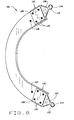
- slider joints 100 and 100' in accordance with a preferred embodiment of the present invention.
- the slider joint 100 is used to mount an upper end portion 108 of a cascade support ring 102 to a hinge beam 104 of a thrust reverser.
- the slider joint 100' is also used to mount a lower end portion 108' of the cascade support ring 102 to a latch beam 104' of the thrust reverser.
- each slider joint 100, 100' includes a fitting 106, 106' disposed at the respective upper and lower end portions 108, 108' of the cascade support ring 102.
- the fitting 106 disposed at the upper end portion 108 includes an engagement portion 110 sized to be slidably received within a track 112 defined by the hinge beam 104.
- the fitting 106' disposed at the lower end portion 108' of the cascade support ring 102 includes an engagement portion 110' sized to be slidably received within a track 112' defined by the latch beam 104'.
- the tracks can be defined by the upper and lower end portions of the cascade support rings with the fittings being disposed on the hinge and latch beams.
- the fitting 106 disposed at the upper end portion 108 of the cascade support ring 102 will also be referred to as the first fitting 106
- the fitting 106' disposed at the lower end portion 108' of the cascade support ring 102 will also be referred to as the second fitting 106'.
- the track 112 defined by the hinge beam 104 will also be referred to as the first track 112
- the track 112' defined by the latch beam 104' will also be referred to as the second track 112'.
- each engagement portion 110, 110' has a cross-section that is substantially circular.
- other cross-sectional shapes e.g., rectangular are also possible for the engagement portions depending on the particular application in which the slider joints 100 and 100' will be used.
- each engagement portion 110, 110' is lined or covered with a suitable friction-reducing, wear-resistant material.
- the engagement portions 110, 110' are covered with a wear-resistant tape 114, 114' that prevents, or at least substantially reduces, wear-and-tear on the engagement portions 110, 110'.
- a wide range of materials may be used for the cascade support ring 102 and/or the first and second fittings 106, 106'.
- lightweight materials are used for the cascade support ring 102 and the fittings 106, 106', such as aluminum or composite materials (e.g., graphite epoxy laminate).
- a wide range of manufacturing processes may be used to fabricate the cascade support ring 102 and the fittings 106 and 106'.
- the cascade support ring 102 may be formed via an extrusion process
- the fittings 106, 106' may be formed via a forging and/or machining process.
- the first and second fittings 106, 106' may be attached to the respective upper and lower end portions 108, 108' of the cascade support ring 102 using any of a wide range of suitable fastening systems or methods (e.g., mechanical fasteners, machining, among others).
- each fitting 106, 106' is bolted to the corresponding end portion 108, 108' of the cascade support ring 102 with nut and bolt assemblies 116, 116'.
- the fittings 106 and/or 106' and the cascade support ring 102 may be integrally formed as a single component.
- the first and second tracks 112, 112' will now be described in further detail.
- the first track 112 is defined by the hinge beam 104 and is sized to slidably receive therein the engagement portion 110 of the first fitting 106.
- the second track 112' is defined by the latch beam 104' and is sized to slidably receive therein the engagement portion 110' of the second fitting 106'.
- the first and second tracks 112, 112' each have a cross section that is substantially c-shaped.
- the tracks may have a cross section that is substantially u-shaped with corners forming right angles.
- Other cross-sectional shapes, however, are also possible for the tracks depending on the particular application in which the slider joints 100 and 100' will be used.
- each track 112, 112' is lined with a suitable friction-reducing, wear-resistant material.
- a steel liner 120, 120 is disposed adjacent the inner surface of each track 112, 112.
- the steel liner 120, 120' reduces the friction between the track 112, 112' and the corresponding engagement portion 110, 110' positioned within the track 112, 112'.
- the steel liner 120, 120' also prevents, or at least reduces, wear-and-tear of the tracks 112, 112'.
- a wide range of materials may be used for the tracks 112, 112'.
- a lightweight material is preferably used for the tracks 112, 112', such as aluminum.
- the hinge beam 104 and the first track 112 are integrally formed as a single component.
- the latch beam 104' and the second track 112' are also formed as a single component.
- either or both of the tracks 112, 112' may comprises a separate component that is attached to the corresponding hinge or latch beam 104, 104' using a suitable fastening system or method (e.g., mechanical fasteners, among others).
- the joints 100 and 100' are assembled as follows to mount the cascade support ring 102 to the thrust reverser.
- the cascade support ring 102 and thrust reverser are positioned relative to one another to align the engagement portion 110 of the first fitting 106 with the first track 112 and to align the engagement portion 110' of the second fitting 106' with the second track 112'.
- the cascade support ring 102 and/or the thrust reverser are moved towards one another so that the engagement portions 110, 110' are slidably received within the first and second tracks 112, 112', respectively.
- the joints 100 and 100' support the cascade support ring 102 in the inboard and outboard directions.
- the cascade support ring 102 is restrained in the fore and aft direction by the cascade 126 ( Figure 6) to which the cascade support ring 102 is bolted 128 ( Figure 7).
- the joints 100 and 100' also provide at least some rotational freedom to the engagement portions 110, 110' even while they are positioned within the tracks 112, 112'.
- the engagement portion 110 may be able to rotate clockwise or counterclockwise a few degrees about the point 124 ( Figure 7) when radial loading on the cascade 126 deflects the cascade support ring 102.
- the present invention provides a method of mounting a cascade support ring to a thrust reverser for a jet engine.
- the method comprises: providing the upper end portion 108 of the cascade support ring 102 with the first fitting 106; providing the lower end portion 108' of the cascade support ring 102 with the second fitting 106'; providing the hinge beam 104 of the thrust reverser with the first track 112; providing the latch beam 104' of the thrust reverser with the second track 112'; and slidably positioning the engagement portions 110, 110' of the respective first and second fittings 106, 106' within the first and second tracks 112, 112', respectively.
- the present invention allow cascade support rings to be mounted to thrust reversers more efficiently and easier than the methods presently recognized in the art.
- the present invention eliminates the need for using a drill cage to provide the hinge and latch beams with bolt holes for attachment of the cascade support rings. This, in turn, allows for reductions in assembly time and tooling and part costs.
- the flexibility of the slider joints 100 and 100' allows cascade support rings to shift or float relative to the hinge and latch beams 104, 104', thus allowing the fore and aft end portions of the cascades to be more easily fastened to the torque box 20 and cascade support ring 26.
- slider joints 100 and 100' can be sized considerably smaller and lighter than the bolted joints 25 shown in Figure 5.
- torque loading is transferred from the cascades into the cascade support rings, which then transfer the loads to the hinge and latch beams.
- known methods in the art employ large and heavy bolted joints to mount the cascade support rings to the hinge and latch beams.
- the rotational nature of the slider joints 100 and 100' eliminates, or at least substantially reduces, the ability of the torque loads to react a moment in the plane of the cascade support ring into the hinge and latch beams. Instead, the torque loads are reacted in the form of hoop and reaction loads. Because the slider joints 100 and 100' do not have to accommodate relatively large moments produced by the torque loading, the slider joints 100 and 100' can be sized considerably smaller and lighter than the bolted joints currently being used.
- the invention will be applicable to any of a wide range of aircraft (e.g. but not limited to, commercial jets, private jets, military jets, among others) regardless of the manner in which the aircraft is piloted (e.g., directly, remotely, via automation, or in a combination thereof, among others). Indeed, the present invention should not be limited to just aircraft either. Rather, it is anticipated that the invention will be applicable to other mobile platforms. Accordingly, the specific references to aircraft herein should not be construed as limiting the scope of the present invention to only one specific form/type of aircraft or to aircraft alone.
Landscapes
- Engineering & Computer Science (AREA)
- Chemical & Material Sciences (AREA)
- Combustion & Propulsion (AREA)
- Mechanical Engineering (AREA)
- General Engineering & Computer Science (AREA)
- Turbine Rotor Nozzle Sealing (AREA)
- Pivots And Pivotal Connections (AREA)
- Mounting Of Bearings Or Others (AREA)
Abstract
Description
Claims (18)
- A thrust reverser for a jet engine of a mobile platform, the thrust reverser being of the type having a hinge beam, a latch beam, and at least one cascade support ring, comprising:a first track defined by the hinge beam;a second track defined by the latch beam;a first fitting disposed at an upper end portion of the cascade support ring, the first fitting including an engagement portion slidably positioned within the first track; anda second fitting disposed at a lower end portion of the cascade support ring, the second fitting including an engagement portion slidably positioned within the second track.
- A thrust reverser according to claim 1, said at least one cascade support ring having an upper end portion and a lower end portion.
- The thrust reverser of claim 1 or 2, further comprising a wear-resistant material lining an inner surface of each track.
- The thrust reverser of any of claims 1-3, further comprising a wear-resistant material lining an outer surface of the engagement portion of each fitting.
- The thrust reverser of any of claims 1-4, wherein the mobile platform comprises an aircraft.
- The thrust reverser of any of claims 1-5, wherein:each track comprises a substantially c-shaped cross section; andeach engagement portion comprises a substantially circular cross section.
- The thrust reverser of any of claims 1-6, wherein the fittings are integral to the cascade support ring.
- The thrust reverser of any of claims 1-7, wherein the fittings are attached to the cascade support ring.
- The thrust reverser of any of claims 1-8, wherein:the first track is integral to the hinge beam; andthe second track is integral to the latch beam.
- The thrust reverser of any of claims 1-9, wherein:the first track is attached to the hinge beam; andthe second track is attached to the latch beam.
- The thrust reverser of any of claims 1-10, wherein the fittings are integral to the cascade support ring.
- The thrust reverser of any of claims 1-11, wherein the fittings are attached to the cascade support ring.
- An aircraft, comprising:a jet engine for generating thrust; anda thrust reverser according to any of claims 1-12.
- Apparatus for mounting a cascade support ring to a thrust reverser, the apparatus comprising:at least one track defined by the thrust reverser; andat least one fitting disposed at an end portion of the cascade support ring, the fitting including an engagement portion sized to be slidably received within the track.
- Apparatus for mounting a cascade support ring to a thrust reverser, the apparatus comprising:at least one track defined by one of the thrust reverser and the cascade support ring; andat least one fitting defined by the other one of said thrust reverser and said cascade support ring, the fitting including an engagement portion sized to be slidably received within the track.
- A method of mounting a cascade support ring to a thrust reverser for a jet engine of a mobile platform, the method comprising:providing an upper end portion of the cascade support ring with a first fitting;providing a lower end portion of the cascade support ring with a second fitting;providing a hinge beam of the thrust reverser with a first track sized to slidably receive therein an engagement portion of the first fitting;providing a latch beam of the thrust reverser with a second track sized to slidably receive therein an engagement portion of the second fitting;slidably positioning the engagement portion of the first fitting within the first track; andslidably positioning the engagement portion of the second fitting within the second track.
- A method according to claim 16, wherein the thrust reverser according to any of claims 1-12, and/or an apparatus according to 14 or 15 is used.
- Apparatus according to claim 14 or 15, also including one or more of the features of the thrust reverser according to any of claims 1-13.
Applications Claiming Priority (2)
| Application Number | Priority Date | Filing Date | Title |
|---|---|---|---|
| US368525 | 2003-02-17 | ||
| US10/368,525 US6824101B2 (en) | 2003-02-17 | 2003-02-17 | Apparatus and method for mounting a cascade support ring to a thrust reverser |
Publications (3)
| Publication Number | Publication Date |
|---|---|
| EP1457659A2 true EP1457659A2 (en) | 2004-09-15 |
| EP1457659A3 EP1457659A3 (en) | 2005-04-13 |
| EP1457659B1 EP1457659B1 (en) | 2008-01-09 |
Family
ID=32771408
Family Applications (1)
| Application Number | Title | Priority Date | Filing Date |
|---|---|---|---|
| EP04075467A Expired - Lifetime EP1457659B1 (en) | 2003-02-17 | 2004-02-13 | Apparatus and method for mounting a cascade support ring to a thrust reverser |
Country Status (3)
| Country | Link |
|---|---|
| US (2) | US6824101B2 (en) |
| EP (1) | EP1457659B1 (en) |
| DE (1) | DE602004011130T2 (en) |
Cited By (16)
| Publication number | Priority date | Publication date | Assignee | Title |
|---|---|---|---|---|
| EP1726812A2 (en) | 2005-05-11 | 2006-11-29 | The Boeing Company | Thrust reverser system for an aircraft |
| WO2007147193A1 (en) * | 2006-06-23 | 2007-12-27 | Facc Ag | Guiding carrier for jet engine linings |
| FR2920198A1 (en) * | 2007-08-20 | 2009-02-27 | Aircelle Sa | Beam e.g. upper beam, for grid thrust reverser of jet engine nacelle in aircraft, has integrated part forming cup adapted to be fitted in and fixed on front semi-frame, and including walls with orifices receiving fixation units |
| FR2926605A1 (en) * | 2008-01-18 | 2009-07-24 | Aircelle Sa | 12-HOUR STRUCTURE FOR THRUST INVERTER INCLUDING GRID |
| EP2138697A3 (en) * | 2008-06-23 | 2011-04-27 | Rohr, Inc. | Aft cascade ring with flow deflector portion, corresponding thrust reverser cascade assembly and aircraft engine nacelle |
| FR2965589A1 (en) * | 2010-10-04 | 2012-04-06 | Aircelle Sa | PUSH INVERTER |
| WO2013014350A1 (en) * | 2011-07-27 | 2013-01-31 | Aircelle | Rear frame for a deflection cascade-type thrust reverser structure for a turbo jet engine nacelle |
| EP2388193A3 (en) * | 2010-05-17 | 2014-07-09 | Rohr, Inc. | Guide system for nacelle assembly |
| EP2399827A3 (en) * | 2010-06-23 | 2014-09-03 | Rohr, Inc. | Guide system for nacelle assembly |
| WO2014132011A1 (en) * | 2013-03-01 | 2014-09-04 | Aircelle | Thrust reverser device |
| US9086034B2 (en) | 2011-10-13 | 2015-07-21 | Rohr, Inc. | Thrust reverser cascade assembly with flow deflection shelf |
| EP2937549A1 (en) * | 2014-04-24 | 2015-10-28 | Rohr, Inc. | Thrust reverser with one or more buttressing corner cascade portions |
| CN105114205A (en) * | 2014-03-21 | 2015-12-02 | 罗尔公司 | Thrust reverser for a turbofan engine |
| WO2016001608A1 (en) * | 2014-07-04 | 2016-01-07 | Aircelle | Rear frame for a thrust reverser structure with diversion grids |
| CN105781792A (en) * | 2015-01-14 | 2016-07-20 | 波音公司 | Methods and apparatus to vary reversethrust of aircraft engines |
| EP1852595A3 (en) * | 2006-05-06 | 2017-11-01 | Rolls-Royce plc | Aeroengine thrust reverser |
Families Citing this family (34)
| Publication number | Priority date | Publication date | Assignee | Title |
|---|---|---|---|---|
| FR2830051B1 (en) * | 2001-09-27 | 2003-11-07 | Hurel Hispano Le Havre | LOCKING SYSTEM ON A GRID DRIVE INVERTER |
| US20110101158A1 (en) * | 2005-03-29 | 2011-05-05 | The Boeing Company | Thrust Reversers Including Monolithic Components |
| US7559507B2 (en) * | 2005-06-27 | 2009-07-14 | The Boeing Company | Thrust reversers including locking assemblies for inhibiting deflection |
| US7600371B2 (en) | 2005-10-18 | 2009-10-13 | The Boeing Company | Thrust reversers including support members for inhibiting deflection |
| US20080083210A1 (en) * | 2006-10-04 | 2008-04-10 | Spirit Aerosystems, Inc | Monolithic thrust reverser components |
| US9759087B2 (en) | 2007-08-08 | 2017-09-12 | Rohr, Inc. | Translating variable area fan nozzle providing an upstream bypass flow exit |
| EP2479414B1 (en) * | 2007-08-08 | 2015-06-10 | Rohr, Inc. | Variable area fan nozzle with bypass flow |
| US8201390B2 (en) * | 2007-12-12 | 2012-06-19 | Spirit Aerosystems, Inc. | Partial cascade thrust reverser |
| US8127532B2 (en) * | 2008-11-26 | 2012-03-06 | The Boeing Company | Pivoting fan nozzle nacelle |
| US8959889B2 (en) | 2008-11-26 | 2015-02-24 | The Boeing Company | Method of varying a fan duct nozzle throat area of a gas turbine engine |
| US8322653B2 (en) * | 2009-09-11 | 2012-12-04 | Spirit Aerosystems, Inc. | Hybrid beam for a thrust reverser unit |
| FR2952681B1 (en) | 2009-11-18 | 2017-10-06 | Aircelle Sa | PUSH INVERTER |
| US20110120078A1 (en) * | 2009-11-24 | 2011-05-26 | Schwark Jr Fred W | Variable area fan nozzle track |
| FR2954278B1 (en) * | 2009-12-18 | 2012-01-20 | Aircelle 7303 | SUPPORT STRUCTURE FOR THRUST INVERTER, IN PARTICULAR WITH GRIDS |
| US8869507B2 (en) * | 2010-01-13 | 2014-10-28 | United Technologies Corporation | Translatable cascade thrust reverser |
| US8302907B2 (en) * | 2010-03-04 | 2012-11-06 | Spirit Aerosystems, Inc. | Hybrid torque box for a thrust reverser |
| FR2959487B1 (en) * | 2010-04-29 | 2012-04-13 | Aircelle Sa | PLATFORM FOR AN AIRCRAFT ENGINE |
| FR2963949A1 (en) * | 2010-08-18 | 2012-02-24 | Aircelle Sa | BEAM PARTICULARLY FOR THRUST INVERTER WITH GRILLS |
| FR2965588B1 (en) * | 2010-10-04 | 2015-05-01 | Aircelle Sa | PROPELLANT AIRCRAFT ASSEMBLY |
| US9038367B2 (en) | 2011-09-16 | 2015-05-26 | United Technologies Corporation | Fan case thrust reverser |
| FR2980173B1 (en) * | 2011-09-16 | 2013-10-25 | Aircelle Sa | REPLACEMENT OF NACELLE FOR TURBOJET ENGINE |
| RU2474717C1 (en) * | 2011-10-28 | 2013-02-10 | Российская Федерация, от имени которой выступает Министерство промышленности и торговли Российской Федерации (Минпромторг России) | Gas turbine engine reverser assembly |
| FR2997925B1 (en) | 2012-11-09 | 2016-03-04 | Aircelle Sa | GUIDE ASSEMBLY FOR A MOBILE NACELLAL UNIT FOR A TURBOJET ENGINE |
| FR3010146B1 (en) * | 2013-08-30 | 2015-12-18 | Aircelle Sa | PLATFORM WITH MOBILE SCREEN REVERSE INVERSION DEVICE |
| US10012175B2 (en) * | 2014-05-30 | 2018-07-03 | The Boeing Company | Thrust reverser torque box with discrete major fittings |
| US10161356B2 (en) * | 2014-06-02 | 2018-12-25 | Ge Aviation Systems Llc | Integrated thrust reverser actuation system |
| DE102014221052A1 (en) * | 2014-10-16 | 2016-04-21 | Premium Aerotec Gmbh | Aircraft gas turbine thrust reverser with guide rail |
| FR3029573B1 (en) * | 2014-12-05 | 2019-04-05 | Airbus Operations (S.A.S.) | THRUST INVERTER FOR AN AIRCRAFT ENGINE ASSEMBLY, NACELLE AND CORRESPONDING ENGINE ASSEMBLY |
| US10208708B2 (en) | 2015-01-29 | 2019-02-19 | Rohr, Inc. | Translating cascade hidden blocker door thrust reverser |
| US10316793B2 (en) * | 2016-03-11 | 2019-06-11 | Rohr, Inc. | Thrust reverser track beam with integrated actuator fitting |
| US11022071B2 (en) | 2016-12-21 | 2021-06-01 | The Boeing Company | Load distribution panel assembly, system and method |
| FR3107568B1 (en) * | 2020-02-26 | 2022-02-18 | Safran Nacelles | FORWARD FRAME AND DEVIATION GRID OF AN AIRCRAFT NACELLE THRUST REVERSER |
| CN111703586B (en) * | 2020-05-11 | 2023-05-30 | 中国南方航空股份有限公司 | Replacement method of reverse-pushing C duct sliding rail structure of V2500 engine |
| CN114718758B (en) * | 2021-01-05 | 2023-10-31 | 中国航发商用航空发动机有限责任公司 | Thrust reverser, sliding fitting and forming method thereof |
Family Cites Families (10)
| Publication number | Priority date | Publication date | Assignee | Title |
|---|---|---|---|---|
| GB1052963A (en) * | 1963-09-30 | |||
| US3503211A (en) * | 1968-04-10 | 1970-03-31 | Rohr Corp | Thrust reverser |
| GB1386232A (en) * | 1971-03-31 | 1975-03-05 | Short Brothers & Harland Ltd | Fluid propulsion systems |
| FR2349738A1 (en) * | 1976-04-28 | 1977-11-25 | Gen Electric | Thrust reverser for turbofan engine - has sliding sleeve which blocks fan outlet and exposes cascade of reversing blades |
| US4278220A (en) * | 1979-03-30 | 1981-07-14 | The United States Of America As Represented By The Administrator Of The National Aeronautics And Space Administration | Thrust reverser for a long duct fan engine |
| FR2496766A1 (en) * | 1980-12-23 | 1982-06-25 | Snecma | MOBILE FAIRING GUIDING DEVICE OF A PUSH REVERSING SYSTEM |
| GB2196911B (en) * | 1986-10-30 | 1990-03-14 | Rolls Royce Plc | Thrust reverser |
| US5778659A (en) * | 1994-10-20 | 1998-07-14 | United Technologies Corporation | Variable area fan exhaust nozzle having mechanically separate sleeve and thrust reverser actuation systems |
| FR2821892B1 (en) * | 2001-03-08 | 2003-06-13 | Hispano Suiza Sa | SYSTEM FOR ACTUATING THE MOBILE COVERING OF A DRIVE INVERTER IN A TURBOJET |
| US6584763B2 (en) * | 2001-08-01 | 2003-07-01 | Rohr, Inc. | Lock for the translating sleeve of a turbofan engine thrust reverser |
-
2003
- 2003-02-17 US US10/368,525 patent/US6824101B2/en not_active Expired - Lifetime
-
2004
- 2004-02-13 DE DE602004011130T patent/DE602004011130T2/en not_active Expired - Lifetime
- 2004-02-13 EP EP04075467A patent/EP1457659B1/en not_active Expired - Lifetime
- 2004-02-13 US US10/779,184 patent/US6915984B2/en not_active Expired - Lifetime
Cited By (33)
| Publication number | Priority date | Publication date | Assignee | Title |
|---|---|---|---|---|
| EP1726812A3 (en) * | 2005-05-11 | 2011-12-07 | The Boeing Company | Thrust reverser system for an aircraft |
| EP1726812A2 (en) | 2005-05-11 | 2006-11-29 | The Boeing Company | Thrust reverser system for an aircraft |
| EP1852595A3 (en) * | 2006-05-06 | 2017-11-01 | Rolls-Royce plc | Aeroengine thrust reverser |
| WO2007147193A1 (en) * | 2006-06-23 | 2007-12-27 | Facc Ag | Guiding carrier for jet engine linings |
| FR2920198A1 (en) * | 2007-08-20 | 2009-02-27 | Aircelle Sa | Beam e.g. upper beam, for grid thrust reverser of jet engine nacelle in aircraft, has integrated part forming cup adapted to be fitted in and fixed on front semi-frame, and including walls with orifices receiving fixation units |
| WO2009053560A3 (en) * | 2007-08-20 | 2009-09-17 | Aircelle | Structure for thrust inverter |
| US8789355B2 (en) | 2007-08-20 | 2014-07-29 | Aircelle | Support structure and mounting componet for a thrust inverter |
| RU2487822C2 (en) * | 2008-01-18 | 2013-07-20 | Эрсель | Structural element for thrust reverser, in particular, equipped with grates and arranged at "12 hours" |
| FR2926605A1 (en) * | 2008-01-18 | 2009-07-24 | Aircelle Sa | 12-HOUR STRUCTURE FOR THRUST INVERTER INCLUDING GRID |
| WO2009106763A3 (en) * | 2008-01-18 | 2009-11-05 | Aircelle | Twelve-hour structure for thrust reverser, in particular with grids |
| US8109466B2 (en) | 2008-06-23 | 2012-02-07 | Rohr, Inc. | Thrust reverser cascade assembly and AFT cascade ring with flow deflector portion |
| EP2138697A3 (en) * | 2008-06-23 | 2011-04-27 | Rohr, Inc. | Aft cascade ring with flow deflector portion, corresponding thrust reverser cascade assembly and aircraft engine nacelle |
| EP2388193A3 (en) * | 2010-05-17 | 2014-07-09 | Rohr, Inc. | Guide system for nacelle assembly |
| EP2399827A3 (en) * | 2010-06-23 | 2014-09-03 | Rohr, Inc. | Guide system for nacelle assembly |
| CN103154435A (en) * | 2010-10-04 | 2013-06-12 | 埃尔塞乐公司 | Thrust reverser |
| WO2012045970A1 (en) * | 2010-10-04 | 2012-04-12 | Aircelle | Thrust reverser |
| FR2965589A1 (en) * | 2010-10-04 | 2012-04-06 | Aircelle Sa | PUSH INVERTER |
| CN103154435B (en) * | 2010-10-04 | 2015-09-09 | 埃尔塞乐公司 | Trhrust-reversal device |
| US8899013B2 (en) | 2010-10-04 | 2014-12-02 | Aircelle | Thrust reverser having locking/unlocking cascade vanes |
| WO2013014350A1 (en) * | 2011-07-27 | 2013-01-31 | Aircelle | Rear frame for a deflection cascade-type thrust reverser structure for a turbo jet engine nacelle |
| FR2978497A1 (en) * | 2011-07-27 | 2013-02-01 | Aircelle Sa | REAR FRAME FOR A THRUST INVERSION STRUCTURE WITH DEVIATION GRIDS OF A TURBOJET NACELLE |
| US9086034B2 (en) | 2011-10-13 | 2015-07-21 | Rohr, Inc. | Thrust reverser cascade assembly with flow deflection shelf |
| FR3002785A1 (en) * | 2013-03-01 | 2014-09-05 | Aircelle Sa | TRANSLATANT AND FIXED GRIDS WITH A T / R O-DUCT. |
| WO2014132011A1 (en) * | 2013-03-01 | 2014-09-04 | Aircelle | Thrust reverser device |
| US10190538B2 (en) | 2013-03-01 | 2019-01-29 | Aircelle | Thrust reverser device |
| CN105114205A (en) * | 2014-03-21 | 2015-12-02 | 罗尔公司 | Thrust reverser for a turbofan engine |
| CN105114205B (en) * | 2014-03-21 | 2018-07-03 | 罗尔公司 | For the trhrust-reversal device of fanjet |
| EP2937549A1 (en) * | 2014-04-24 | 2015-10-28 | Rohr, Inc. | Thrust reverser with one or more buttressing corner cascade portions |
| WO2016001608A1 (en) * | 2014-07-04 | 2016-01-07 | Aircelle | Rear frame for a thrust reverser structure with diversion grids |
| FR3023325A1 (en) * | 2014-07-04 | 2016-01-08 | Aircelle Sa | REAR FRAME FOR A DEVIATION GRID REVERSING INVERTER STRUCTURE |
| US10677193B2 (en) | 2014-07-04 | 2020-06-09 | Safran Nacelles | Rear frame for a thrust reverser structure with diversion grids |
| CN105781792A (en) * | 2015-01-14 | 2016-07-20 | 波音公司 | Methods and apparatus to vary reversethrust of aircraft engines |
| CN105781792B (en) * | 2015-01-14 | 2019-10-29 | 波音公司 | Change the method and apparatus of the propulsive thrust of aircraft engine |
Also Published As
| Publication number | Publication date |
|---|---|
| EP1457659B1 (en) | 2008-01-09 |
| EP1457659A3 (en) | 2005-04-13 |
| DE602004011130T2 (en) | 2008-11-06 |
| US20040159741A1 (en) | 2004-08-19 |
| US6824101B2 (en) | 2004-11-30 |
| US20040159091A1 (en) | 2004-08-19 |
| US6915984B2 (en) | 2005-07-12 |
| DE602004011130D1 (en) | 2008-02-21 |
Similar Documents
| Publication | Publication Date | Title |
|---|---|---|
| US6824101B2 (en) | Apparatus and method for mounting a cascade support ring to a thrust reverser | |
| US10011373B1 (en) | Tensioning apparatus and system for clamping joints | |
| EP3275788B1 (en) | Sliding joint kits, systems containing the same, and related methods | |
| US10703512B2 (en) | Printed spacecraft separation system | |
| EP3401222B1 (en) | Engine exhaust duct mounting assembly | |
| EP3770407B1 (en) | Engine mount seal for gas turbine | |
| US20120171019A1 (en) | Attachment interface for a gas turbine engine composite duct structure | |
| US10273830B2 (en) | Replacing an aperture with an annular bushing in a composite laminated composite component | |
| EP2937549B1 (en) | Thrust reverser with one or more buttressing corner cascade portions | |
| EP0623742B1 (en) | Nozzle seal assembly for a gas turbine engine exhaust nozzle | |
| US11702230B2 (en) | Non-sealing berthing system for spacecraft | |
| US9511845B2 (en) | Aircraft frame | |
| EP3549856A1 (en) | Fan cowl latch concept for fuselage mounted power plant | |
| US20110064515A1 (en) | Anchor and splice plate assembly for axially split composite duct or pressure vessel | |
| US5127606A (en) | Aircraft engine mount adapter and method | |
| JPH04342830A (en) | Shearing wire flange coupling | |
| US7216922B2 (en) | Fairing panel retainer apparatus | |
| CA3182303A1 (en) | System and method for assembling an aft fuselage section of an aircraft | |
| EP2865878B1 (en) | Gimbal pin for jet propulsion system | |
| EP3896299B1 (en) | Hinged assembly with fail-safe hinge pin | |
| EP3800126A1 (en) | Cowl door latch assembly | |
| US6497530B1 (en) | Universal flange joint for attaching | |
| US20240102778A1 (en) | Mechanism for attachment and detachment of an airfoil to an airframe | |
| US12448136B2 (en) | Two-piece engine collar | |
| US12214911B2 (en) | Load coupling attachment systems and methods |
Legal Events
| Date | Code | Title | Description |
|---|---|---|---|
| PUAI | Public reference made under article 153(3) epc to a published international application that has entered the european phase |
Free format text: ORIGINAL CODE: 0009012 |
|
| AK | Designated contracting states |
Kind code of ref document: A2 Designated state(s): AT BE BG CH CY CZ DE DK EE ES FI FR GB GR HU IE IT LI LU MC NL PT RO SE SI SK TR |
|
| AX | Request for extension of the european patent |
Extension state: AL HR LT LV MK |
|
| PUAL | Search report despatched |
Free format text: ORIGINAL CODE: 0009013 |
|
| AK | Designated contracting states |
Kind code of ref document: A3 Designated state(s): AT BE BG CH CY CZ DE DK EE ES FI FR GB GR HU IE IT LI LU MC NL PT RO SE SI SK TR |
|
| AX | Request for extension of the european patent |
Extension state: AL HR LT LV MK |
|
| RIC1 | Information provided on ipc code assigned before grant |
Ipc: 7F 02K 1/09 B Ipc: 7F 02K 1/62 B Ipc: 7F 02K 1/72 A Ipc: 7F 02K 1/80 B Ipc: 7F 02K 1/70 B |
|
| 17P | Request for examination filed |
Effective date: 20050428 |
|
| AKX | Designation fees paid |
Designated state(s): DE FR GB |
|
| GRAP | Despatch of communication of intention to grant a patent |
Free format text: ORIGINAL CODE: EPIDOSNIGR1 |
|
| GRAS | Grant fee paid |
Free format text: ORIGINAL CODE: EPIDOSNIGR3 |
|
| GRAA | (expected) grant |
Free format text: ORIGINAL CODE: 0009210 |
|
| AK | Designated contracting states |
Kind code of ref document: B1 Designated state(s): DE FR GB |
|
| REG | Reference to a national code |
Ref country code: GB Ref legal event code: FG4D |
|
| REF | Corresponds to: |
Ref document number: 602004011130 Country of ref document: DE Date of ref document: 20080221 Kind code of ref document: P |
|
| ET | Fr: translation filed | ||
| RAP2 | Party data changed (patent owner data changed or rights of a patent transferred) |
Owner name: THE BOEING COMPANY |
|
| PLBE | No opposition filed within time limit |
Free format text: ORIGINAL CODE: 0009261 |
|
| STAA | Information on the status of an ep patent application or granted ep patent |
Free format text: STATUS: NO OPPOSITION FILED WITHIN TIME LIMIT |
|
| 26N | No opposition filed |
Effective date: 20081010 |
|
| REG | Reference to a national code |
Ref country code: FR Ref legal event code: PLFP Year of fee payment: 13 |
|
| REG | Reference to a national code |
Ref country code: FR Ref legal event code: PLFP Year of fee payment: 14 |
|
| REG | Reference to a national code |
Ref country code: FR Ref legal event code: PLFP Year of fee payment: 15 |
|
| PGFP | Annual fee paid to national office [announced via postgrant information from national office to epo] |
Ref country code: FR Payment date: 20230223 Year of fee payment: 20 |
|
| PGFP | Annual fee paid to national office [announced via postgrant information from national office to epo] |
Ref country code: GB Payment date: 20230227 Year of fee payment: 20 Ref country code: DE Payment date: 20230223 Year of fee payment: 20 |
|
| P01 | Opt-out of the competence of the unified patent court (upc) registered |
Effective date: 20230503 |
|
| REG | Reference to a national code |
Ref country code: DE Ref legal event code: R071 Ref document number: 602004011130 Country of ref document: DE |
|
| REG | Reference to a national code |
Ref country code: GB Ref legal event code: PE20 Expiry date: 20240212 |
|
| PG25 | Lapsed in a contracting state [announced via postgrant information from national office to epo] |
Ref country code: GB Free format text: LAPSE BECAUSE OF EXPIRATION OF PROTECTION Effective date: 20240212 |