EP1457421A2 - Multi-edged cutter - Google Patents
Multi-edged cutter Download PDFInfo
- Publication number
- EP1457421A2 EP1457421A2 EP04003261A EP04003261A EP1457421A2 EP 1457421 A2 EP1457421 A2 EP 1457421A2 EP 04003261 A EP04003261 A EP 04003261A EP 04003261 A EP04003261 A EP 04003261A EP 1457421 A2 EP1457421 A2 EP 1457421A2
- Authority
- EP
- European Patent Office
- Prior art keywords
- cutter
- die holder
- cutting
- accordance
- projections
- Prior art date
- Legal status (The legal status is an assumption and is not a legal conclusion. Google has not performed a legal analysis and makes no representation as to the accuracy of the status listed.)
- Granted
Links
Images

Classifications
-
- B—PERFORMING OPERATIONS; TRANSPORTING
- B01—PHYSICAL OR CHEMICAL PROCESSES OR APPARATUS IN GENERAL
- B01F—MIXING, e.g. DISSOLVING, EMULSIFYING OR DISPERSING
- B01F35/00—Accessories for mixers; Auxiliary operations or auxiliary devices; Parts or details of general application
- B01F35/75—Discharge mechanisms
- B01F35/751—Discharging by opening a gate, e.g. using discharge paddles
-
- B—PERFORMING OPERATIONS; TRANSPORTING
- B65—CONVEYING; PACKING; STORING; HANDLING THIN OR FILAMENTARY MATERIAL
- B65B—MACHINES, APPARATUS OR DEVICES FOR, OR METHODS OF, PACKAGING ARTICLES OR MATERIALS; UNPACKING
- B65B13/00—Bundling articles
- B65B13/18—Details of, or auxiliary devices used in, bundling machines or bundling tools
-
- B—PERFORMING OPERATIONS; TRANSPORTING
- B01—PHYSICAL OR CHEMICAL PROCESSES OR APPARATUS IN GENERAL
- B01F—MIXING, e.g. DISSOLVING, EMULSIFYING OR DISPERSING
- B01F23/00—Mixing according to the phases to be mixed, e.g. dispersing or emulsifying
- B01F23/60—Mixing solids with solids
-
- B—PERFORMING OPERATIONS; TRANSPORTING
- B01—PHYSICAL OR CHEMICAL PROCESSES OR APPARATUS IN GENERAL
- B01F—MIXING, e.g. DISSOLVING, EMULSIFYING OR DISPERSING
- B01F35/00—Accessories for mixers; Auxiliary operations or auxiliary devices; Parts or details of general application
- B01F35/75—Discharge mechanisms
- B01F35/754—Discharge mechanisms characterised by the means for discharging the components from the mixer
- B01F35/75415—Discharge mechanisms characterised by the means for discharging the components from the mixer using gravity
-
- B—PERFORMING OPERATIONS; TRANSPORTING
- B01—PHYSICAL OR CHEMICAL PROCESSES OR APPARATUS IN GENERAL
- B01F—MIXING, e.g. DISSOLVING, EMULSIFYING OR DISPERSING
- B01F35/00—Accessories for mixers; Auxiliary operations or auxiliary devices; Parts or details of general application
- B01F35/80—Forming a predetermined ratio of the substances to be mixed
- B01F35/88—Forming a predetermined ratio of the substances to be mixed by feeding the materials batchwise
-
- B—PERFORMING OPERATIONS; TRANSPORTING
- B23—MACHINE TOOLS; METAL-WORKING NOT OTHERWISE PROVIDED FOR
- B23D—PLANING; SLOTTING; SHEARING; BROACHING; SAWING; FILING; SCRAPING; LIKE OPERATIONS FOR WORKING METAL BY REMOVING MATERIAL, NOT OTHERWISE PROVIDED FOR
- B23D35/00—Tools for shearing machines or shearing devices; Holders or chucks for shearing tools
- B23D35/002—Means for mounting the cutting members
-
- B—PERFORMING OPERATIONS; TRANSPORTING
- B65—CONVEYING; PACKING; STORING; HANDLING THIN OR FILAMENTARY MATERIAL
- B65B—MACHINES, APPARATUS OR DEVICES FOR, OR METHODS OF, PACKAGING ARTICLES OR MATERIALS; UNPACKING
- B65B61/00—Auxiliary devices, not otherwise provided for, for operating on sheets, blanks, webs, binding material, containers or packages
- B65B61/04—Auxiliary devices, not otherwise provided for, for operating on sheets, blanks, webs, binding material, containers or packages for severing webs, or for separating joined packages
- B65B61/06—Auxiliary devices, not otherwise provided for, for operating on sheets, blanks, webs, binding material, containers or packages for severing webs, or for separating joined packages by cutting
-
- B—PERFORMING OPERATIONS; TRANSPORTING
- B23—MACHINE TOOLS; METAL-WORKING NOT OTHERWISE PROVIDED FOR
- B23D—PLANING; SLOTTING; SHEARING; BROACHING; SAWING; FILING; SCRAPING; LIKE OPERATIONS FOR WORKING METAL BY REMOVING MATERIAL, NOT OTHERWISE PROVIDED FOR
- B23D35/00—Tools for shearing machines or shearing devices; Holders or chucks for shearing tools
- B23D35/001—Tools for shearing machines or shearing devices; Holders or chucks for shearing tools cutting members
-
- B—PERFORMING OPERATIONS; TRANSPORTING
- B26—HAND CUTTING TOOLS; CUTTING; SEVERING
- B26D—CUTTING; DETAILS COMMON TO MACHINES FOR PERFORATING, PUNCHING, CUTTING-OUT, STAMPING-OUT OR SEVERING
- B26D1/00—Cutting through work characterised by the nature or movement of the cutting member or particular materials not otherwise provided for; Apparatus or machines therefor; Cutting members therefor
- B26D1/0006—Cutting members therefor
-
- B—PERFORMING OPERATIONS; TRANSPORTING
- B26—HAND CUTTING TOOLS; CUTTING; SEVERING
- B26D—CUTTING; DETAILS COMMON TO MACHINES FOR PERFORATING, PUNCHING, CUTTING-OUT, STAMPING-OUT OR SEVERING
- B26D1/00—Cutting through work characterised by the nature or movement of the cutting member or particular materials not otherwise provided for; Apparatus or machines therefor; Cutting members therefor
- B26D1/0006—Cutting members therefor
- B26D2001/0053—Cutting members therefor having a special cutting edge section or blade section
-
- B—PERFORMING OPERATIONS; TRANSPORTING
- B26—HAND CUTTING TOOLS; CUTTING; SEVERING
- B26D—CUTTING; DETAILS COMMON TO MACHINES FOR PERFORATING, PUNCHING, CUTTING-OUT, STAMPING-OUT OR SEVERING
- B26D1/00—Cutting through work characterised by the nature or movement of the cutting member or particular materials not otherwise provided for; Apparatus or machines therefor; Cutting members therefor
- B26D1/0006—Cutting members therefor
- B26D2001/006—Cutting members therefor the cutting blade having a special shape, e.g. a special outline, serrations
-
- B—PERFORMING OPERATIONS; TRANSPORTING
- B26—HAND CUTTING TOOLS; CUTTING; SEVERING
- B26D—CUTTING; DETAILS COMMON TO MACHINES FOR PERFORATING, PUNCHING, CUTTING-OUT, STAMPING-OUT OR SEVERING
- B26D11/00—Combinations of several similar cutting apparatus
- B26D2011/005—Combinations of several similar cutting apparatus in combination with different kind of cutters, e.g. two serial slitters in combination with a transversal cutter
-
- Y—GENERAL TAGGING OF NEW TECHNOLOGICAL DEVELOPMENTS; GENERAL TAGGING OF CROSS-SECTIONAL TECHNOLOGIES SPANNING OVER SEVERAL SECTIONS OF THE IPC; TECHNICAL SUBJECTS COVERED BY FORMER USPC CROSS-REFERENCE ART COLLECTIONS [XRACs] AND DIGESTS
- Y10—TECHNICAL SUBJECTS COVERED BY FORMER USPC
- Y10S—TECHNICAL SUBJECTS COVERED BY FORMER USPC CROSS-REFERENCE ART COLLECTIONS [XRACs] AND DIGESTS
- Y10S83/00—Cutting
- Y10S83/955—Cutter edge shiftable to present different portion of edge
Definitions
- the present invention is directed to a multi-edged cutting mechanism for use with strapping tools. More particularly, the present invention pertains to a multi-edged cutting mechanism having cutting surfaces defining elongate cutting edges, retaining surfaces, and a movable die holder with a slot defining tabs having a support surface for the cutting body.
- multi-edged cutters for, portable or hand-held strapping tools so that when one cutting edge wears out, a replacement is immediately available.
- multi-edge cutters include the triple edged cutters of U.S. Patents Nos. 5,499,664 and 5,848,621.
- cutters provide a single cutting edge, which moves up and down with the motion of a holder.
- One such strapping tool commercially available from ITW SIGNODE CORPORATION of Glenview, Illinois, attaches a single-edged cutter to a die holder with a pin.
- a cutter support surface on the die holder forces the cutting edge through a strap.
- the attaching pin pulls the cutter back up.
- Cutters that provide multiple cutting edges such as the cutters described in the above-cited patents, frequently require separate cutting holders and include return springs to return the cutter during the upstroke.
- return springs to return the cutter during the upstroke.
- a multi-edged cutting mechanism that provides a simple means of connecting the cutting surfaces and edges to the rest of the cutting mechanism.
- Such a cutting mechanism reduces the number of parts and conveniently provides at least one immediately available replacement cutter. It also protects the cutting edges not in use from any damage.
- a cutting mechanism for use with a strapping tool includes a cutter having a polygonal cross-sectional configuration, cutting surfaces defining elongate cutting edges, and retaining recesses formed in a body of the cutter.
- the cutting edges are an in-use edge and a spare edge.
- the mechanism includes a movable die holder having a support surface for supporting the cutter body.
- the support surface includes projections extending outwardly therefrom for supporting the cutter.
- the cutter is reversible on the die holder such that the in-use and spare cutting edges are interchangeable by rotation of the cutter.
- a slot is defined between the projections such that a central portion of the cutter body (between the recesses) fits within the support surface slot.
- the cutter is reversible about the projections.
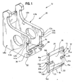
- FIG. 1 is a perspective view of a multi-edged cutting mechanism for use with strapping tools embodying the principles of the present invention, the cutter being shown removed from the cutting mechanism;
- FIG. 2 is a perspective view of the cutting mechanism similar to FIG. 1, showing the cutter engaged with the die holder.
- the cutting mechanism includes a die holder 30 and a cutter 12.
- the cutter 12 has a body portion 13 having a polygonal cross-sectional configuration that defines first and second laterally opposed cutting surfaces 14a,b, and 16a,b respectively, at each end.
- the cutting surfaces 14a,b and 16a,b define first and second elongate, parallel cutting edges 18, 20 respectively.
- the body 13 has first and second (or front and rear) generally parallel surfaces 15a,b that extend between the cutting surfaces 14a,b and 16a,b.
- the body 13 further defines first and second laterally opposed recesses or notches 26, 28 formed therein.
- the recesses 26, 28 are disposed such that the cutting edges 18, 20 are symmetrically disposed thereabout. That is, the edges 18, 20 are mirror images of each other relative to the recesses 26, 28.
- the recesses 26, 28 are formed as rectangular notches in longitudinal sides 27, 29 of the body 13.
- the notches 26, 28 define inner walls 31, 33 at their closest-most locations.
- the recesses 26, 28 each define first and second laterally opposed retaining surfaces 22a,b and 24a,b, respectively.
- the cutting edges 18, 20 and retaining surfaces 22a,b, 24a,b are parallel to one another.
- the retaining surfaces 22a,b and 24a,b are perpendicular to the longitudinal sides edges 27, 29.
- the movable die holder 30 is supported by the strapping tool and has a support surface 32, against which a lower portion of the cutter 12 rests.
- a two-part projection or shoulder 36, 38 extends outwardly from the surface 32 for engaging the cutter 12.
- the two-part projection 36, 38 defines a slot 34 therebetween within which the central portion 36 of the cutter body 13 (between the notches 26, 28) is positioned.
- the slot 34 is centrally located along the support surface 32.
- the projections 36, 38 are configured so that the recesses 26, 28 of the cutter 12 fit over the projections 36, 38, and so that the cutter 12 is laterally held in place by the projections 36, 38 abutting the notch inner walls 31, 33.
- an upper portion of the holder is formed having parallel, upstanding spaced apart walls 40a,b spaced from one another.
- the space 40c between the walls 40a,b is configured for receipt of a shaft, cam and sealer arrangement (not shown) for forming a seal in the strap material.
- the upper portion of the holder, at a corresponding upper portion of the cutter is formed as two walls (indicated generally at 42a,b), the edges of which bear the cutter 12 when it is in position on the holder 30.
- Lip 44a,b are formed at an uppermost region of each of the walls 40a,b to define surfaces 43a,b which facilitate guiding the holder 30 in the strapper tool base (not shown).
- the cutter 12 is shown engaged to the die holder 30.
- the cutter 12 and die holder 30 move up and down together to perform strap cutting functions.
- the projections 36, 38 force the cutter 12 down, and thus the first cutting edge 18 through a strap.
- the projections 36, 38 lift the cutter 12, and maintain an appropriate spacing so that the second cutting edge 20, which is not in use, does not sustain any damage, as by contacting the upper wall lips 44a,b. No return arrangement other than the upward urging of the projections 36, 38 of the holder 30 acting on the cutter 12 are required.
- the cutter 12 is removed from the die holder 30 and is "flipped", reversing the spent edge 18 with the second or spare cutting edge 20.
- the cutter 12 is replaced in the die holder 30, so that the recesses 26, 28 once more fit over the projections 36, 38, and the strapping tool is again ready to use.
Landscapes
- Engineering & Computer Science (AREA)
- Mechanical Engineering (AREA)
- Chemical & Material Sciences (AREA)
- Chemical Kinetics & Catalysis (AREA)
- Basic Packing Technique (AREA)
- Perforating, Stamping-Out Or Severing By Means Other Than Cutting (AREA)
- Knives (AREA)
- Wire Processing (AREA)
Abstract
Description
Claims (11)
- A cutting mechanism for use with a strapping tool, comprising:wherein the cutter is reversible on the die holder such that the in-use and spare cutting edges are interchangeable by rotation of the cutter.a movable die holder mounted to the strapping tool, the die holder having a support surface, the die holder including a plurality of projections extending outwardly therefrom, at least some of the projections being in opposing relation to others of the projections and defining a slot between the opposing projections;a cutter defining a body portion having a polygonal cross-sectional configuration, the cutter having a pair of opposing, mirror image cutting surfaces on opposing ends thereof defining an in-use and a spare elongate cutting edge, the cutter body having recesses formed in longitudinal sides of the body portion , the cutter configured for receipt on the die holder support surface and engagement with the die holder projections,
- The cutting mechanism in accordance with claim 1 wherein the plurality of cutting surfaces are first and second surfaces laterally opposed to each other, defining the in-use and spare elongate, parallel cutting edges.
- The cutting mechanism in accordance with claim 1 wherein the recesses are formed as first and second laterally opposed, mirror image recesses, centrally located along the longitudinal sides.
- The cutting mechanism in accordance with claim 3 wherein the first and second opposed recesses define a central portion of the cutter body therebetween.
- The cutting mechanism in accordance with claim 1 wherein the die holder support surface slot is configured for receipt of the cutter body central portion.
- The cutting mechanism in accordance with claim 1 wherein the die holder support surface slot is centrally located.
- The cutting mechanism in accordance with claim 1 wherein the die holder includes a lip defining a recess between the lip and the projections for receipt of a portion of the cutter.
- A cutter for use with a strapping tool, the cutter configured for receipt in a die holder mounted to the strapping tool, the cutter comprising:a body portion having a polygonal cross-sectional configuration, the cutter having opposing, mirror image cutting surfaces defining a pair of opposing, mirror image elongate cutting edges, pair being an in-use cutting edge and a spare cutting edge, the cutter having a plurality of retaining notches formed therein to secure the body portion with the die holder surfaces, the cutter being reversible on the die holder such that the in-use and spare cutting edges are interchangeable by rotation of the cutter.
- The cutter in accordance with claim 8 wherein the plurality of retaining notches is formed as first and second laterally opposed recesses centrally located in opposing longitudinal sides of the body portion.
- The cutter in accordance with claim 9 wherein the notches are formed as rectangular recesses in the longitudinal sides and defme a central portion of the body therebetween.
- The cutter in accordance with claim 10 wherein the rectangular recesses are centrally located.
Applications Claiming Priority (2)
| Application Number | Priority Date | Filing Date | Title |
|---|---|---|---|
| US10/384,955 US6871673B2 (en) | 2003-03-10 | 2003-03-10 | Multi-edged cutter |
| US384955 | 2003-03-10 |
Publications (3)
| Publication Number | Publication Date |
|---|---|
| EP1457421A2 true EP1457421A2 (en) | 2004-09-15 |
| EP1457421A3 EP1457421A3 (en) | 2007-04-18 |
| EP1457421B1 EP1457421B1 (en) | 2010-04-07 |
Family
ID=32771562
Family Applications (1)
| Application Number | Title | Priority Date | Filing Date |
|---|---|---|---|
| EP04003261A Expired - Lifetime EP1457421B1 (en) | 2003-03-10 | 2004-02-13 | Multi-edged cutter |
Country Status (13)
| Country | Link |
|---|---|
| US (1) | US6871673B2 (en) |
| EP (1) | EP1457421B1 (en) |
| JP (1) | JP4504041B2 (en) |
| KR (1) | KR101163556B1 (en) |
| CN (1) | CN100361872C (en) |
| AT (1) | ATE463426T1 (en) |
| AU (1) | AU2004201013B2 (en) |
| BR (1) | BRPI0400178B1 (en) |
| CA (1) | CA2454876C (en) |
| DE (1) | DE602004026378D1 (en) |
| MX (1) | MXPA04002273A (en) |
| NZ (1) | NZ531203A (en) |
| TW (1) | TWI235126B (en) |
Families Citing this family (12)
| Publication number | Priority date | Publication date | Assignee | Title |
|---|---|---|---|---|
| GB2385550A (en) * | 2002-02-20 | 2003-08-27 | Colin Maxwell Wade | Punch for a ductile material joining tool |
| US8146256B2 (en) | 2003-10-31 | 2012-04-03 | Stanley Black & Decker, Inc. | Metal demolition shears with indexable, integrated wear plate/piercing tip |
| US20070173183A1 (en) * | 2006-01-25 | 2007-07-26 | Keene Milford M | Cutting tool with integrated abrasive trimming elements |
| USD552638S1 (en) * | 2006-06-20 | 2007-10-09 | Ahwi Maschinenbau Gmbh | Cutting body for rotors used to pulverize organic materials |
| USD556797S1 (en) * | 2006-12-08 | 2007-12-04 | Awhi Maschinenbau Gmbh | Cutting body |
| US7837138B2 (en) * | 2007-05-03 | 2010-11-23 | Riley Power, Inc. | Swing hammer for particulate size reduction system |
| US7591451B2 (en) * | 2007-11-13 | 2009-09-22 | Hellermanntyton Corporation | Bundle tie tensioning clutch |
| USD616002S1 (en) * | 2008-03-07 | 2010-05-18 | Ahwi Maschinenbau Gmbh | Cutting tool |
| TWI386277B (en) * | 2010-01-26 | 2013-02-21 | Magpro Technology Co Ltd | Tool holder which connects to a tool without noise |
| DE102012005764A1 (en) * | 2012-03-23 | 2013-09-26 | Deere & Company | binding device |
| EP3826651A4 (en) * | 2018-07-24 | 2022-05-11 | Healeon LLC | DEVICE AND METHOD FOR RESIZING FAT TISSUE AND OTHER TISSUES FOR IMPLANTATION |
| CN113665871B (en) * | 2021-08-18 | 2022-10-25 | 深圳市业安商贸有限公司 | Chemical material barrel bundling equipment for chemical material selling |
Family Cites Families (14)
| Publication number | Priority date | Publication date | Assignee | Title |
|---|---|---|---|---|
| GB191218637A (en) * | 1912-08-14 | 1913-07-03 | William Eric Bousfield | Improvements in Safety Razors. |
| JPS5121189U (en) * | 1974-08-05 | 1976-02-16 | ||
| JPS557247Y2 (en) * | 1976-05-12 | 1980-02-18 | ||
| JPS58102402U (en) * | 1981-12-28 | 1983-07-12 | ナイガイ株式会社 | Packing tape cutting device in packaging machine |
| JPS60171806U (en) * | 1984-04-25 | 1985-11-14 | 窪田 石松 | Cutting blade in vegetable binding machine |
| KR910008441B1 (en) * | 1988-09-02 | 1991-10-15 | 나시모토 고오교오 가부시끼가이샤 | Mowing blade |
| DE9004377U1 (en) * | 1990-04-17 | 1990-07-05 | Gämmerler, Hagen, 8021 Icking | Rotary cutting device, especially for individual paper products |
| JPH04112799A (en) * | 1990-09-04 | 1992-04-14 | Nagase Seikagaku Kogyo Kk | Method for determining oxalic acid or salts thereof |
| US5097874A (en) * | 1991-04-07 | 1992-03-24 | Signode Corporation | Strapping head with strap tail-flattening capability |
| JPH06262593A (en) * | 1993-03-17 | 1994-09-20 | Sekisui Chem Co Ltd | Cutting device of sticky film |
| US5499664A (en) * | 1994-03-07 | 1996-03-19 | Illinois Tool Works Inc. | Compressive cutting mechanism having plural-edged cutter |
| JPH0885667A (en) * | 1994-09-16 | 1996-04-02 | Takeshi Suzuki | Paper storage type cutter and adhesive tape holder therewith |
| US5848621A (en) * | 1996-03-22 | 1998-12-15 | Illinois Tool Works Inc. | Cutter for steel strapping tool |
| NZ519013A (en) * | 2001-05-21 | 2003-05-30 | Orgapack Gmbh | Manually actuated strapping unit for wrapping a steel strap around a packaged item |
-
2003
- 2003-03-10 US US10/384,955 patent/US6871673B2/en not_active Expired - Lifetime
- 2003-12-30 CA CA002454876A patent/CA2454876C/en not_active Expired - Lifetime
-
2004
- 2004-01-06 TW TW093100285A patent/TWI235126B/en not_active IP Right Cessation
- 2004-02-06 JP JP2004030851A patent/JP4504041B2/en not_active Expired - Fee Related
- 2004-02-11 BR BRPI0400178-8A patent/BRPI0400178B1/en not_active IP Right Cessation
- 2004-02-13 AT AT04003261T patent/ATE463426T1/en not_active IP Right Cessation
- 2004-02-13 DE DE602004026378T patent/DE602004026378D1/en not_active Expired - Lifetime
- 2004-02-13 EP EP04003261A patent/EP1457421B1/en not_active Expired - Lifetime
- 2004-02-18 NZ NZ531203A patent/NZ531203A/en unknown
- 2004-02-26 KR KR1020040012970A patent/KR101163556B1/en not_active Expired - Fee Related
- 2004-03-05 CN CNB2004100046995A patent/CN100361872C/en not_active Expired - Fee Related
- 2004-03-09 MX MXPA04002273A patent/MXPA04002273A/en active IP Right Grant
- 2004-03-10 AU AU2004201013A patent/AU2004201013B2/en not_active Ceased
Also Published As
| Publication number | Publication date |
|---|---|
| CN100361872C (en) | 2008-01-16 |
| MXPA04002273A (en) | 2004-09-15 |
| EP1457421B1 (en) | 2010-04-07 |
| JP2004269050A (en) | 2004-09-30 |
| CN1530289A (en) | 2004-09-22 |
| BRPI0400178B1 (en) | 2018-06-12 |
| JP4504041B2 (en) | 2010-07-14 |
| CA2454876A1 (en) | 2004-09-10 |
| BRPI0400178A (en) | 2004-12-28 |
| KR101163556B1 (en) | 2012-07-10 |
| TWI235126B (en) | 2005-07-01 |
| CA2454876C (en) | 2007-04-10 |
| US6871673B2 (en) | 2005-03-29 |
| AU2004201013A1 (en) | 2004-09-30 |
| DE602004026378D1 (en) | 2010-05-20 |
| KR20040080976A (en) | 2004-09-20 |
| EP1457421A3 (en) | 2007-04-18 |
| NZ531203A (en) | 2004-09-24 |
| ATE463426T1 (en) | 2010-04-15 |
| TW200420472A (en) | 2004-10-16 |
| US20040177892A1 (en) | 2004-09-16 |
| AU2004201013B2 (en) | 2005-05-19 |
Similar Documents
| Publication | Publication Date | Title |
|---|---|---|
| EP1457421B1 (en) | Multi-edged cutter | |
| US20230158695A1 (en) | Shaving razor cartridge | |
| CN106003163A (en) | Hair trimmer blade set with adjustable blades | |
| JP7349682B2 (en) | Hair removal device blade and hair removal device comprising a hair removal device blade | |
| CA2617478A1 (en) | Multipurpose tool | |
| KR0154402B1 (en) | Work piece compression tool with multi-sided cutter | |
| JP2020500063A (en) | Razor | |
| US8869406B2 (en) | Cutter with anvil | |
| KR101668230B1 (en) | Razor | |
| MX2013014338A (en) | Die shoe assembly with bearing surface mechanism, method for retaining a die, and die for use therewith. | |
| US7143922B2 (en) | Stapler with tape dispenser and flag dispenser | |
| US2184757A (en) | Shaving device | |
| KR100239970B1 (en) | Steel strapping tool cutter | |
| BRPI0801747B1 (en) | CONSTRUCTION GROUP FOR CLOSING TOOL FOR A CLAMPING MACHINE | |
| US11633846B2 (en) | Ergonomic attachment for a ninety degree drill assembly | |
| US6769341B2 (en) | Sheet cutting device | |
| JP7272699B2 (en) | tool holder | |
| JP2532152Y2 (en) | Wire cutting equipment for metal wire processing machines | |
| JP3959463B2 (en) | Material cutting device | |
| US1895840A (en) | Recoil buffer for cutter bars | |
| JP4158209B2 (en) | Hoop material cutter hopper | |
| JPH0657278B2 (en) | Reciprocating electric razor | |
| JPS61199883A (en) | Electric razor | |
| JP2002166390A (en) | Cutting equipment |
Legal Events
| Date | Code | Title | Description |
|---|---|---|---|
| PUAI | Public reference made under article 153(3) epc to a published international application that has entered the european phase |
Free format text: ORIGINAL CODE: 0009012 |
|
| AK | Designated contracting states |
Kind code of ref document: A2 Designated state(s): AT BE BG CH CY CZ DE DK EE ES FI FR GB GR HU IE IT LI LU MC NL PT RO SE SI SK TR |
|
| AX | Request for extension of the european patent |
Extension state: AL LT LV MK |
|
| PUAL | Search report despatched |
Free format text: ORIGINAL CODE: 0009013 |
|
| AK | Designated contracting states |
Kind code of ref document: A3 Designated state(s): AT BE BG CH CY CZ DE DK EE ES FI FR GB GR HU IE IT LI LU MC NL PT RO SE SI SK TR |
|
| AX | Request for extension of the european patent |
Extension state: AL LT LV MK |
|
| RIC1 | Information provided on ipc code assigned before grant |
Ipc: B65B 13/18 20060101ALI20070313BHEP Ipc: B65B 13/06 20060101AFI20040707BHEP Ipc: B65B 61/06 20060101ALI20070313BHEP Ipc: B26D 7/26 20060101ALI20070313BHEP |
|
| 17P | Request for examination filed |
Effective date: 20070402 |
|
| 17Q | First examination report despatched |
Effective date: 20070627 |
|
| AKX | Designation fees paid |
Designated state(s): AT BE BG CH CY CZ DE DK EE ES FI FR GB GR HU IE IT LI LU MC NL PT RO SE SI SK TR |
|
| GRAP | Despatch of communication of intention to grant a patent |
Free format text: ORIGINAL CODE: EPIDOSNIGR1 |
|
| RIN1 | Information on inventor provided before grant (corrected) |
Inventor name: FIGIEL, JANUSZ Inventor name: CRITTENDEN, DAVID E. |
|
| GRAS | Grant fee paid |
Free format text: ORIGINAL CODE: EPIDOSNIGR3 |
|
| GRAA | (expected) grant |
Free format text: ORIGINAL CODE: 0009210 |
|
| AK | Designated contracting states |
Kind code of ref document: B1 Designated state(s): AT BE BG CH CY CZ DE DK EE ES FI FR GB GR HU IE IT LI LU MC NL PT RO SE SI SK TR |
|
| REG | Reference to a national code |
Ref country code: GB Ref legal event code: FG4D |
|
| REG | Reference to a national code |
Ref country code: CH Ref legal event code: EP |
|
| REG | Reference to a national code |
Ref country code: IE Ref legal event code: FG4D |
|
| REF | Corresponds to: |
Ref document number: 602004026378 Country of ref document: DE Date of ref document: 20100520 Kind code of ref document: P |
|
| REG | Reference to a national code |
Ref country code: NL Ref legal event code: VDEP Effective date: 20100407 |
|
| PG25 | Lapsed in a contracting state [announced via postgrant information from national office to epo] |
Ref country code: SI Free format text: LAPSE BECAUSE OF FAILURE TO SUBMIT A TRANSLATION OF THE DESCRIPTION OR TO PAY THE FEE WITHIN THE PRESCRIBED TIME-LIMIT Effective date: 20100407 |
|
| PG25 | Lapsed in a contracting state [announced via postgrant information from national office to epo] |
Ref country code: SE Free format text: LAPSE BECAUSE OF FAILURE TO SUBMIT A TRANSLATION OF THE DESCRIPTION OR TO PAY THE FEE WITHIN THE PRESCRIBED TIME-LIMIT Effective date: 20100407 Ref country code: NL Free format text: LAPSE BECAUSE OF FAILURE TO SUBMIT A TRANSLATION OF THE DESCRIPTION OR TO PAY THE FEE WITHIN THE PRESCRIBED TIME-LIMIT Effective date: 20100407 Ref country code: ES Free format text: LAPSE BECAUSE OF FAILURE TO SUBMIT A TRANSLATION OF THE DESCRIPTION OR TO PAY THE FEE WITHIN THE PRESCRIBED TIME-LIMIT Effective date: 20100718 |
|
| PG25 | Lapsed in a contracting state [announced via postgrant information from national office to epo] |
Ref country code: FI Free format text: LAPSE BECAUSE OF FAILURE TO SUBMIT A TRANSLATION OF THE DESCRIPTION OR TO PAY THE FEE WITHIN THE PRESCRIBED TIME-LIMIT Effective date: 20100407 Ref country code: AT Free format text: LAPSE BECAUSE OF FAILURE TO SUBMIT A TRANSLATION OF THE DESCRIPTION OR TO PAY THE FEE WITHIN THE PRESCRIBED TIME-LIMIT Effective date: 20100407 |
|
| PG25 | Lapsed in a contracting state [announced via postgrant information from national office to epo] |
Ref country code: CY Free format text: LAPSE BECAUSE OF FAILURE TO SUBMIT A TRANSLATION OF THE DESCRIPTION OR TO PAY THE FEE WITHIN THE PRESCRIBED TIME-LIMIT Effective date: 20100414 Ref country code: GR Free format text: LAPSE BECAUSE OF FAILURE TO SUBMIT A TRANSLATION OF THE DESCRIPTION OR TO PAY THE FEE WITHIN THE PRESCRIBED TIME-LIMIT Effective date: 20100708 |
|
| PG25 | Lapsed in a contracting state [announced via postgrant information from national office to epo] |
Ref country code: EE Free format text: LAPSE BECAUSE OF FAILURE TO SUBMIT A TRANSLATION OF THE DESCRIPTION OR TO PAY THE FEE WITHIN THE PRESCRIBED TIME-LIMIT Effective date: 20100407 Ref country code: DK Free format text: LAPSE BECAUSE OF FAILURE TO SUBMIT A TRANSLATION OF THE DESCRIPTION OR TO PAY THE FEE WITHIN THE PRESCRIBED TIME-LIMIT Effective date: 20100407 Ref country code: PT Free format text: LAPSE BECAUSE OF FAILURE TO SUBMIT A TRANSLATION OF THE DESCRIPTION OR TO PAY THE FEE WITHIN THE PRESCRIBED TIME-LIMIT Effective date: 20100809 |
|
| PLBE | No opposition filed within time limit |
Free format text: ORIGINAL CODE: 0009261 |
|
| STAA | Information on the status of an ep patent application or granted ep patent |
Free format text: STATUS: NO OPPOSITION FILED WITHIN TIME LIMIT |
|
| PG25 | Lapsed in a contracting state [announced via postgrant information from national office to epo] |
Ref country code: RO Free format text: LAPSE BECAUSE OF FAILURE TO SUBMIT A TRANSLATION OF THE DESCRIPTION OR TO PAY THE FEE WITHIN THE PRESCRIBED TIME-LIMIT Effective date: 20100407 Ref country code: CZ Free format text: LAPSE BECAUSE OF FAILURE TO SUBMIT A TRANSLATION OF THE DESCRIPTION OR TO PAY THE FEE WITHIN THE PRESCRIBED TIME-LIMIT Effective date: 20100407 Ref country code: BE Free format text: LAPSE BECAUSE OF FAILURE TO SUBMIT A TRANSLATION OF THE DESCRIPTION OR TO PAY THE FEE WITHIN THE PRESCRIBED TIME-LIMIT Effective date: 20100407 Ref country code: SK Free format text: LAPSE BECAUSE OF FAILURE TO SUBMIT A TRANSLATION OF THE DESCRIPTION OR TO PAY THE FEE WITHIN THE PRESCRIBED TIME-LIMIT Effective date: 20100407 |
|
| 26N | No opposition filed |
Effective date: 20110110 |
|
| PG25 | Lapsed in a contracting state [announced via postgrant information from national office to epo] |
Ref country code: IT Free format text: LAPSE BECAUSE OF FAILURE TO SUBMIT A TRANSLATION OF THE DESCRIPTION OR TO PAY THE FEE WITHIN THE PRESCRIBED TIME-LIMIT Effective date: 20100407 |
|
| PG25 | Lapsed in a contracting state [announced via postgrant information from national office to epo] |
Ref country code: MC Free format text: LAPSE BECAUSE OF NON-PAYMENT OF DUE FEES Effective date: 20110228 |
|
| REG | Reference to a national code |
Ref country code: CH Ref legal event code: PL |
|
| PG25 | Lapsed in a contracting state [announced via postgrant information from national office to epo] |
Ref country code: LI Free format text: LAPSE BECAUSE OF NON-PAYMENT OF DUE FEES Effective date: 20110228 Ref country code: CH Free format text: LAPSE BECAUSE OF NON-PAYMENT OF DUE FEES Effective date: 20110228 |
|
| REG | Reference to a national code |
Ref country code: IE Ref legal event code: MM4A |
|
| PG25 | Lapsed in a contracting state [announced via postgrant information from national office to epo] |
Ref country code: IE Free format text: LAPSE BECAUSE OF NON-PAYMENT OF DUE FEES Effective date: 20110213 |
|
| PG25 | Lapsed in a contracting state [announced via postgrant information from national office to epo] |
Ref country code: LU Free format text: LAPSE BECAUSE OF NON-PAYMENT OF DUE FEES Effective date: 20110213 |
|
| PG25 | Lapsed in a contracting state [announced via postgrant information from national office to epo] |
Ref country code: TR Free format text: LAPSE BECAUSE OF FAILURE TO SUBMIT A TRANSLATION OF THE DESCRIPTION OR TO PAY THE FEE WITHIN THE PRESCRIBED TIME-LIMIT Effective date: 20100407 Ref country code: BG Free format text: LAPSE BECAUSE OF FAILURE TO SUBMIT A TRANSLATION OF THE DESCRIPTION OR TO PAY THE FEE WITHIN THE PRESCRIBED TIME-LIMIT Effective date: 20100707 |
|
| PG25 | Lapsed in a contracting state [announced via postgrant information from national office to epo] |
Ref country code: HU Free format text: LAPSE BECAUSE OF FAILURE TO SUBMIT A TRANSLATION OF THE DESCRIPTION OR TO PAY THE FEE WITHIN THE PRESCRIBED TIME-LIMIT Effective date: 20100407 |
|
| REG | Reference to a national code |
Ref country code: GB Ref legal event code: 732E Free format text: REGISTERED BETWEEN 20140424 AND 20140430 |
|
| REG | Reference to a national code |
Ref country code: GB Ref legal event code: 732E Free format text: REGISTERED BETWEEN 20140717 AND 20140723 |
|
| REG | Reference to a national code |
Ref country code: DE Ref legal event code: R081 Ref document number: 602004026378 Country of ref document: DE Owner name: PREMARK PACKAGING LLC, GLENVIEW, US Free format text: FORMER OWNER: ILLINOIS TOOL WORKS INC., GLENVIEW, ILL., US Effective date: 20140729 Ref country code: DE Ref legal event code: R081 Ref document number: 602004026378 Country of ref document: DE Owner name: SIGNODE INTERNATIONAL IP HOLDINGS LLC, GLENVIE, US Free format text: FORMER OWNER: ILLINOIS TOOL WORKS INC., GLENVIEW, ILL., US Effective date: 20140729 |
|
| REG | Reference to a national code |
Ref country code: FR Ref legal event code: TP Owner name: PREMARK PACKAGING LLC, US Effective date: 20140827 |
|
| REG | Reference to a national code |
Ref country code: DE Ref legal event code: R081 Ref document number: 602004026378 Country of ref document: DE Owner name: SIGNODE INTERNATIONAL IP HOLDINGS LLC, GLENVIE, US Free format text: FORMER OWNER: PREMARK PACKAGING LLC, GLENVIEW, ILL., US Effective date: 20140912 |
|
| REG | Reference to a national code |
Ref country code: FR Ref legal event code: TP Owner name: SIGNODE INTERNATIONAL IP HOLDINGS LLC, US Effective date: 20150127 |
|
| REG | Reference to a national code |
Ref country code: FR Ref legal event code: PLFP Year of fee payment: 13 |
|
| REG | Reference to a national code |
Ref country code: FR Ref legal event code: PLFP Year of fee payment: 14 |
|
| REG | Reference to a national code |
Ref country code: FR Ref legal event code: PLFP Year of fee payment: 15 |
|
| PGFP | Annual fee paid to national office [announced via postgrant information from national office to epo] |
Ref country code: FR Payment date: 20210223 Year of fee payment: 18 |
|
| PGFP | Annual fee paid to national office [announced via postgrant information from national office to epo] |
Ref country code: GB Payment date: 20210225 Year of fee payment: 18 |
|
| PGFP | Annual fee paid to national office [announced via postgrant information from national office to epo] |
Ref country code: DE Payment date: 20220225 Year of fee payment: 19 |
|
| GBPC | Gb: european patent ceased through non-payment of renewal fee |
Effective date: 20220213 |
|
| PG25 | Lapsed in a contracting state [announced via postgrant information from national office to epo] |
Ref country code: FR Free format text: LAPSE BECAUSE OF NON-PAYMENT OF DUE FEES Effective date: 20220228 |
|
| PG25 | Lapsed in a contracting state [announced via postgrant information from national office to epo] |
Ref country code: GB Free format text: LAPSE BECAUSE OF NON-PAYMENT OF DUE FEES Effective date: 20220213 |
|
| REG | Reference to a national code |
Ref country code: DE Ref legal event code: R119 Ref document number: 602004026378 Country of ref document: DE |
|
| PG25 | Lapsed in a contracting state [announced via postgrant information from national office to epo] |
Ref country code: DE Free format text: LAPSE BECAUSE OF NON-PAYMENT OF DUE FEES Effective date: 20230901 |