EP1457418B1 - Personal flotation device - Google Patents
Personal flotation device Download PDFInfo
- Publication number
- EP1457418B1 EP1457418B1 EP04005211A EP04005211A EP1457418B1 EP 1457418 B1 EP1457418 B1 EP 1457418B1 EP 04005211 A EP04005211 A EP 04005211A EP 04005211 A EP04005211 A EP 04005211A EP 1457418 B1 EP1457418 B1 EP 1457418B1
- Authority
- EP
- European Patent Office
- Prior art keywords
- floatation
- package
- waist
- panel
- personal
- Prior art date
- Legal status (The legal status is an assumption and is not a legal conclusion. Google has not performed a legal analysis and makes no representation as to the accuracy of the status listed.)
- Expired - Lifetime
Links
- 238000005188 flotation Methods 0.000 title 1
- 238000004873 anchoring Methods 0.000 claims abstract description 29
- 239000000463 material Substances 0.000 claims abstract description 17
- 239000006260 foam Substances 0.000 description 26
- 230000000712 assembly Effects 0.000 description 11
- 238000000429 assembly Methods 0.000 description 11
- XLYOFNOQVPJJNP-UHFFFAOYSA-N water Substances O XLYOFNOQVPJJNP-UHFFFAOYSA-N 0.000 description 4
- 238000004519 manufacturing process Methods 0.000 description 2
- 239000004677 Nylon Substances 0.000 description 1
- 229920001778 nylon Polymers 0.000 description 1
Images

Classifications
-
- A—HUMAN NECESSITIES
- A41—WEARING APPAREL
- A41D—OUTERWEAR; PROTECTIVE GARMENTS; ACCESSORIES
- A41D13/00—Professional, industrial or sporting protective garments, e.g. surgeons' gowns or garments protecting against blows or punches
- A41D13/012—Professional, industrial or sporting protective garments, e.g. surgeons' gowns or garments protecting against blows or punches for aquatic activities, e.g. with buoyancy aids
- A41D13/0125—Professional, industrial or sporting protective garments, e.g. surgeons' gowns or garments protecting against blows or punches for aquatic activities, e.g. with buoyancy aids with buoyancy aids
-
- B—PERFORMING OPERATIONS; TRANSPORTING
- B63—SHIPS OR OTHER WATERBORNE VESSELS; RELATED EQUIPMENT
- B63C—LAUNCHING, HAULING-OUT, OR DRY-DOCKING OF VESSELS; LIFE-SAVING IN WATER; EQUIPMENT FOR DWELLING OR WORKING UNDER WATER; MEANS FOR SALVAGING OR SEARCHING FOR UNDERWATER OBJECTS
- B63C9/00—Life-saving in water
- B63C9/08—Life-buoys, e.g. rings; Life-belts, jackets, suits, or the like
- B63C9/11—Life-buoys, e.g. rings; Life-belts, jackets, suits, or the like covering the torso, e.g. harnesses
- B63C9/115—Life-buoys, e.g. rings; Life-belts, jackets, suits, or the like covering the torso, e.g. harnesses using solid buoyant material
-
- B—PERFORMING OPERATIONS; TRANSPORTING
- B63—SHIPS OR OTHER WATERBORNE VESSELS; RELATED EQUIPMENT
- B63B—SHIPS OR OTHER WATERBORNE VESSELS; EQUIPMENT FOR SHIPPING
- B63B2231/00—Material used for some parts or elements, or for particular purposes
- B63B2231/40—Synthetic materials
- B63B2231/50—Foamed synthetic materials
Definitions
- the field of the present invention is floatation devices, and more specifically, personal floatation devices, also referred to as life vests or life jackets.
- PFD personal floatation devices
- Floatation packages are generally made of material such as foam.
- Floatation packages made of foam are bulky.
- Many PFD's arrange the foam in both of the two front floatation packages and in the back floatation package to fit the wearer's body beginning just above the wearer's waist and extending upward to the wearer's shoulders.
- Most PFD's provide a generally equal distribution of foam in the front and back floatation packages, with just slightly more foam in the front. There is a drawback to such PFD's in situations where the wearer sits in a chair with a back support structure.
- kayaks and other boats have seats with back supports.
- the back floatation package of most PFD's being made of foam that fits just above the wearer's waist
- the foam in the back floatation package of the vest interferes with the back support of the chair.
- the result of wearing such a PFD in a chair with a back support is that the body of the wearer is forced forward in such a back-supported seat.
- Such forward-sitting prevents the wearer from sitting safely, comfortably, and securely in a back-supported seat.
- GB 05197 discloses a personal floatation device comprising a life vest, said life vest comprising a left front floatation package having a left front shoulder portion, a right front floatation package having a right front shoulder portion, a back floatation package fitting high on the back shoulders of a wearer in a back shoulder yoke position, said back floatation package having a lower edge, said back floatation package adjustably connected to the left front shoulder portion of the left front floatation package; said back floatation package adjustably connected to the right front shoulder portion of the right front floatation package.
- the present invention provides a personal floatation device characterised in that said life vest further comprises a back non-floatation anchoring means connected to the lower edge of the back floatation package, said back non-floatation anchoring means extending vertically from the lower edge of the back floatation package to a waist of the life vest.
- the back non-floatation anchoring means extends vertically (longitudinally) from the lower edge of the back floatation package to a waist of the vest.
- the back non-floatation anchoring means may comprise a panel of material, a panel of mesh material, a configuration of straps, either adjustable or nonadjustable, or other anchoring means.
- the back non-floatation panel extends horizontally (latitudinally) from a right side portion of a back of the vest to a left side portion of the back of the vest.
- the terms “horizontally” and “latitudinally” are both used interchangeably herein to refer to elements of the present invention that, when an embodiment of the present invention is in an upright position such as when it is worn, or is in an upright position as to be worn, or is hung upright on a clothes hanger, extend from one side, e.g., the left side, to another side, e.g., the right side, of the vest of the present invention.
- the present invention is a type of garment that can be placed in various positions or folded in any number of variations; certain spatially-relevant descriptive terms used herein are used to describe the relative positions of elements of the present invention when an embodiment of the present invention is in an upright position such as when it is worn, or is in an upright position as to be worn, or is hung upright on a clothes hanger; that when an embodiment of the present invention is in some alternative position, such as, for example, laying flat, folded, stuffed into a duffle bag, or hung upside down from or folded over a clothes line, the elements described will be in positions other than as described herein.
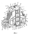
- FIG.1 is a perspective view of an exemplary PFD of the present invention.
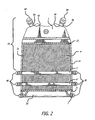
- FIG. 2 is a plan view of the back portion of the exemplary PFD of the present invention.
- the exemplary embodiment of the present invention provides a back floatation package 1.
- the back floatation package 1 is connected to a back non-floatation panel 4.
- the back non-floatation panel 4 of the exemplary embodiment of the present invention connects at an edge 13 to the back floatation package 1.
- the back floatation package 1 of the exemplary embodiment of the present invention is generally formed in the shape of a shoulder yoke, such as a shoulder yoke panel on the upper back shoulders of a men's sport shirt.
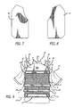
- the back floatation package 1 is designed to fit the upper back shoulder yoke position 10 of a wearer 12 (see FIGS. 9 and 10).
- FIG. 10 is a back view of a person 12, depicting a projection of a back floatation package 1' of the present invention onto the upper back shoulder yoke position 10 of the person 12.
- the back floatation package 1 (see, e.g., FIG. 2) of the exemplary embodiment of the present invention is constructed with a yoke-shaped shell envelope 32 of material initially providing an opening at the bottom edge 33.
- a foam package 30 with a skive 31 (a skive is a beveled edge) is inserted into the yoke-shaped shell envelope 32 of material.
- the foam package 30 is inserted.
- the bottom of the shell envelope, with the foam package 30 inserted, and a top edge of the back non-floatation panel inserted, is closed, such as by stitching.
Abstract
Description
- The field of the present invention is floatation devices, and more specifically, personal floatation devices, also referred to as life vests or life jackets.
- Many personal floatation devices ("PFD", "PFD's") provide a back floatation package that is connected to two front floatation packages to form a vest. Floatation packages are generally made of material such as foam. Floatation packages made of foam are bulky. Many PFD's arrange the foam in both of the two front floatation packages and in the back floatation package to fit the wearer's body beginning just above the wearer's waist and extending upward to the wearer's shoulders. Most PFD's provide a generally equal distribution of foam in the front and back floatation packages, with just slightly more foam in the front. There is a drawback to such PFD's in situations where the wearer sits in a chair with a back support structure. For example, kayaks and other boats have seats with back supports. As a consequence of the back floatation package of most PFD's being made of foam that fits just above the wearer's waist, when the wearer wears the vest and tries to sit in a chair with a back support structure, the foam in the back floatation package of the vest interferes with the back support of the chair. The result of wearing such a PFD in a chair with a back support is that the body of the wearer is forced forward in such a back-supported seat. Such forward-sitting prevents the wearer from sitting safely, comfortably, and securely in a back-supported seat.
- GB 05197 discloses a personal floatation device comprising a life vest, said life vest comprising a left front floatation package having a left front shoulder portion, a right front floatation package having a right front shoulder portion, a back floatation package fitting high on the back shoulders of a wearer in a back shoulder yoke position, said back floatation package having a lower edge, said back floatation package adjustably connected to the left front shoulder portion of the left front floatation package; said back floatation package adjustably connected to the right front shoulder portion of the right front floatation package.
- It is an object of the invention to provide a PFD, which fits a wearer better.
- The present invention provides a personal floatation device characterised in that said life vest further comprises a back non-floatation anchoring means connected to the lower edge of the back floatation package, said back non-floatation anchoring means extending vertically from the lower edge of the back floatation package to a waist of the life vest. The back non-floatation anchoring means extends vertically (longitudinally) from the lower edge of the back floatation package to a waist of the vest. In various embodiments, the back non-floatation anchoring means may comprise a panel of material, a panel of mesh material, a configuration of straps, either adjustable or nonadjustable, or other anchoring means. In the exemplary embodiment, the back non-floatation panel extends horizontally (latitudinally) from a right side portion of a back of the vest to a left side portion of the back of the vest.
- It should be noted that herein, the terms "horizontally" and "latitudinally" are both used interchangeably herein to refer to elements of the present invention that, when an embodiment of the present invention is in an upright position such as when it is worn, or is in an upright position as to be worn, or is hung upright on a clothes hanger, extend from one side, e.g., the left side, to another side, e.g., the right side, of the vest of the present invention.
- The terms "vertically" and "longitudinally" are both used interchangeably herein to refer to elements of the present invention that, when an embodiment of the present invention is in an upright position such as when it is worn, or is in an upright position as to be worn, or is hung upright on a clothes hanger, extend from a point at one level to a point at a lower level of the vest of the present invention.
- It will be understood by someone with ordinary skill in the art that the present invention is a type of garment that can be placed in various positions or folded in any number of variations; certain spatially-relevant descriptive terms used herein are used to describe the relative positions of elements of the present invention when an embodiment of the present invention is in an upright position such as when it is worn, or is in an upright position as to be worn, or is hung upright on a clothes hanger; that when an embodiment of the present invention is in some alternative position, such as, for example, laying flat, folded, stuffed into a duffle bag, or hung upside down from or folded over a clothes line, the elements described will be in positions other than as described herein.
- These and other features of the present invention are more fully set forth in the following description of exemplary embodiments of the invention. The description is presented with reference to the accompanying drawings in which:
- FIG.1 is a perspective view of an exemplary personal floatation device ("PFD") of the present invention;
- FIG. 2 is a plan view of the back portion of the exemplary PFD of the present invention;
- FIG. 3 is a plan view of an exemplary back floatation package shell foam package in an exemplary embodiment of the present invention;
- FIG. 4 is a plan view of an exemplary back floatation package shell envelope in an exemplary embodiment of the present invention;
- FIG. 5 is a plan view of an exemplary top front left foam package in an exemplary embodiment of the present invention;
- FIG. 6 is a plan view of an exemplary bottom from right foam package in an exemplary embodiment of the present invention;
- FIG. 7 is a plan view of an exemplary left front floatation package shell envelope in an exemplary embodiment of the present invention;
- FIG. 8 is a plan view of an exemplary right front floatation package shell envelope in an exemplary embodiment of the present invention;
- FIG. 9 is a back view of the exemplary vest of the present invention as fitted on a wearer;
- FIG. 10 is a back view of a person, depicting a projection of an exemplary back floatation package of the present invention onto the back shoulders of the person;
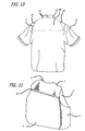
- FIG. 11 is a perspective view of the back of an alternative exemplary embodiment of the present invention;
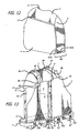
- FIG. 12 is a perspective view of the back of a second alternative exemplary embodiment of the present invention; and
- FIG. 13 is a perspective view of the front of a third alternative exemplary embodiment of the present invention.
- FIG.1 is a perspective view of an exemplary PFD of the present invention. FIG. 2 is a plan view of the back portion of the exemplary PFD of the present invention. As depicted in FIGS. 1 and 2, the exemplary embodiment of the present invention provides a
back floatation package 1. Theback floatation package 1 is connected to aback non-floatation panel 4. Theback non-floatation panel 4 of the exemplary embodiment of the present invention connects at anedge 13 to theback floatation package 1. - The
back floatation package 1 of the exemplary embodiment of the present invention is generally formed in the shape of a shoulder yoke, such as a shoulder yoke panel on the upper back shoulders of a men's sport shirt. Theback floatation package 1 is designed to fit the upper backshoulder yoke position 10 of a wearer 12 (see FIGS. 9 and 10). FIG. 10 is a back view of aperson 12, depicting a projection of a back floatation package 1' of the present invention onto the upper backshoulder yoke position 10 of theperson 12. - As depicted in FIGS. 3 and 4, the back floatation package 1 (see, e.g., FIG. 2) of the exemplary embodiment of the present invention is constructed with a yoke-
shaped shell envelope 32 of material initially providing an opening at thebottom edge 33. Afoam package 30 with a skive 31 (a skive is a beveled edge) is inserted into the yoke-shaped shell envelope 32 of material. Thefoam package 30 is inserted. The bottom of the shell envelope, with thefoam package 30 inserted, and a top edge of the back non-floatation panel inserted, is closed, such as by stitching. - As depicted in FIGS. 9 and 10, the
back floatation package 1 of the exemplary embodiment of the present invention extends horizontally, latitudinally (when the exemplary vest of the present invention is in an upright "worn" position) across an upper back shoulder yoke portion 10' of the vest of the present invention from an upper leftback shoulder position 15 to an upper rightback shoulder position 16. As depicted in FIGS. 9 and 10, the back floatation package has atop 17. The top 17 of the exemplaryback floatation package 1 begins at the rearneck collar position 18 of thewearer 12. As depicted in FIG. 9, theback floatation package 1 of the exemplary embodiment of the present invention has alower edge 13 that extends horizontally (latitudinally) from a rear left-armmid-sleeve position 19 to a rear right-arm mid-sleeve position 20. - As depicted in FIG. 2, the
back floatation package 1 of the exemplary embodiment of the present invention has upper back left andright shoulder edges straps right shoulder edges straps right shoulder edges - The
back non-floatation panel 4 of the exemplary embodiment of the present invention is comprised of mesh. Someone with ordinary skill in the art will understand that mesh is exemplary and is illustrative of the type of material that can be used as theback non-floatation panel 4 and is not a limitation of the invention. - The
back non-floatation panel 4 of the exemplary embodiment of the present invention is connected to theback floatation package 1 at thelower edge 13 of theback floatation package 1.Binding tape 21 is sewn along both sides of theback non-floatation panel 4 of the exemplary embodiment of the present invention. A panel of material is sewn to thebottom 23 of theback non-floatation panel 4 and is doubled back and sewn to form atunnel 22. Thetunnel 22 is a waist securing means through which a strap may be inserted. - The exemplary embodiment of the present invention provides
straps non-floatation panel 4. In the exemplary embodiment of the present invention, straps 5, 6 and 7 comprise nylon webbing. In the exemplary embodiment of the present invention,Strap 5 is sewn horizontally (latitudinally) across the backnon-floatation panel 4 at approximately a mid-rib position.Strap 7 is inserted through thetunnel 22.Strap 6 is sewn horizontally (latitudinally) across the backnon-floatation panel 4 in betweenStraps Straps non-floatation panel 4. Further, straps 5, 6 and 7 provide strength for adjusting the fit ofback 1 andfront 2 and 3 (see FIG. 1) floatation packages on a wearer. The ends ofstraps tunnel 22 andstrap 7 are designed to be positioned at the waist of the wearer. - Reference herein to a "waist" of the vest will be understood to include the portion of the vest that touches or reaches, or the portions of the components of the vest that touch or reach, the approximate location of a wearer's waist. For example, shoulder straps (
e.g. elements tunnel 22, andtunnels - As depicted in FIG. 1, the exemplary embodiment of the present invention further provides two
front floatation packages front floatation packages straps straps straps straps strap 8a withstrap 8b withstrap adjustment feature 40; andstrap 9a withstrap 9b withstrap adjustment feature 40, are adjustable. - Each
front floatation package 2 and 3 (as shown in FIG. 1) of the exemplary embodiment is constructed by inserting two foam packages, atop foam package 35 as depicted in FIG. 5, and abottom foam package 37 as depicted in FIG. 6, into each of right and left front floatation package shell envelopes 50 (FIG. 7) and 51 (FIG. 8) respectively. - The exemplary
top foam package 35 depicted in FIG. 5 is for a left front (left from the wearer's perspective)floatation package 2. The exemplarytop foam package 35 depicted in FIG. 5 has a skive (a beveled edge) 36. When thetop foam package 35 is inserted into a floatation package, thetop foam package 35 is inserted with the skived side facing out (away from the wearer). - The exemplary
bottom foam package 37 depicted in FIG. 6 is for a right front (right from the wearer's perspective)floatation package 3. The exemplarybottom foam package 37 depicted in FIG. 6 has askive 38. When thebottom foam package 37 is inserted into a floatation package, thebottom foam package 37 is inserted with the skived side down (facing the wearer's body) - that is, thebottom foam package 37 would be turned on the reverse side from the way it is depicted in FIG. 6. - Once a top and a
bottom foam package tunnel 53 and 54 (FIG. 1) of material is formed, such as by stitching, at the bottom of eachpackage tunnels front floatation packages - Continuing with reference to FIG. 1, straps 67a and 67b are threaded through the
tunnels end 67a' and 67b' (not shown) respectively of eachstrap strap 7; theends 67a' and 67b' (not shown) respectively ofstraps end 67a' and 67b' (not shown) respectively of each ofstraps - Continuing with reference to FIG. 1, the
other end 67a" and 67b" respectively of eachstrap male buckle element 56 and afemale buckle element 55 respectively. Each of the buckle ends 67a" and 67b" respectively of eachstrap tunnel -
Straps front floatation packages straps straps ends 66a' and 66b' (not shown), and 65a' and 65b' (not shown) respectively, ofstraps - Side strap assemblies, e.g.,
strap 5 withstrap 65a withstrap adjustment feature 40;strap 6 withstrap 66a withstrap adjustment feature 40;strap 7 withstrap 67a withstrap adjustment feature 40, are adjustable. - Continuing with reference to FIG. 1, additional strap and buckle assemblies, e.g., 57, 58, 59, are provided for closure of the front of the vest. It will be understood that the number and positioning of the front closure strap and buckle assemblies are exemplary and are not a limitation of the invention - more or fewer strap and buckle assemblies could be used.
- In the exemplary embodiment, the shoulder strap assemblies (8a/8b/40 and 9a/9b/40) can be adjusted so that the back tunnel 22 (shown in FIGS. 1 and 2) and
front package tunnels - When the back tunnel 22 (shown in FIGS. 1 and 2) and
front package tunnels closure buckle assembly buckle assembly non-floatation panel 4 to the back of the wearer and thereby anchors theback floatation package 1. - Anchoring the
back floatation package 1 prevents theback floatation package 1 from floating. If theback floatation package 1 were not so anchored, theback floatation package 1 would be free to float at or above the head of a wearer 12 (FIG. 9) once thewearer 12 is in water. If theback floatation package 1 were free to float at or above the head of awearer 12 in water, the vest would likely not float thewearer 12 high enough in the water to provide sufficient water life-saving support. - Continuing with reference to FIG. 1, anchoring the
back floatation package 1 with the backnon-floatation panel 4 and waist/side strap assemblies (7/67a/40 and 7/67b/40) not only prevents theback floatation package 1 from floating, but does so without substantially increasing bulkiness at the back of the wearer 12 (e.g., FIG. 9). Because of the anchoring, and because of the yoke high-on-the-back-of-the-shoulders position of theback floatation package 1, awearer 12 can sit in a seat with a back support without interference with the back of the vest. With no added back bulkiness or interference with the back of the vest, the wearer will be able to sit with the wearer's back against the back support of a seat. - Use in the exemplary embodiment of a back
non-floatation panel 4 comprised of mesh to anchor the back floatation panel provides a lightweight water-pass-through anchor for theback floatation package 1. It will be understood by someone with ordinary skill in the art that other means of anchoring theback floatation panel 1 are possible. For example, a backnon-floatation panel 4 could be comprised of non-mesh material. - As another example, as depicted in FIG. 13, instead of a panel of material, straps 4' could be provided to anchor the
back floatation panel 1 to a waist strap 7'. FIG. 13 depicts an exemplary strap anchoring of theback floatation panel 1. As depicted in FIG. 13, vertical straps 4' are provided -- one end of each vertical strap 4' would be attached to thelower edge 13 of theback floatation package 1; the opposite end of each vertical strap 4' would be looped and secured (such as with stitching) to form a tunnel 22' through which a waist strap 7' would be inserted. As depicted in FIG. 13, the vertical straps 4' would provideadjustment features 4a' (e.g., " Ladder Locs"); in further alternative embodiments, the vertical straps 4' may not be adjustable. The waist strap 7' could be adjustable. In further alternative exemplary embodiments, the straps 4' could be provided in non-vertical configurations, such as criss-crossed similar to the back of a man's suspenders. - In one strap anchoring embodiment, the waist strap 7' could be inserted through a tunnel (e.g., 53 and 54 as depicted in FIG. 1) of each of two front floatation panels (e.g., 2 and 3 as depicted in FIG. 1).
- However, in the vertical strap anchoring embodiment depicted in FIG. 13, front tunnels 53' and 54' are loops formed by one or more adjustable straps, e.g., 53a' and 54a'. As depicted in FIG. 13, both ends of each
strap 53a' and 54a' are connected to the bottom of the respectivefront floatation panel front floatation packages - Use in the exemplary embodiment of adjustable shoulder and side strap assemblies enables production of general vest sizes (such as small, medium, large and XXL). It will be understood by someone with ordinary skill in the art that alternative shoulder and side connection materials could be used. However, doing so with non-adjustable materials would require production of size-specific vests (e.g.,
sizes 2 through 20) as opposed to adjustable general vest sizes. For example, as depicted in FIG. 11, the vest of the present invention could be constructed with aback floatation package 1 connected at the shoulders to front floatation panels, 2 and 3; the backnon-floatation panel 4 would be connected to thelower edge 13 of theback floatation package 1; the sides of the backnon-floatation panel 4 would be connected to the front floatation panels 2 (not shown) and 3 (shown). - Further, it will be understood by someone with ordinary skill in the art that in another alternative exemplary embodiment, a single floatation package could be provided as depicted in FIG. 12 with a front portion 2'/3' and a back portion 1'; the back portion 1' of the floatation package of the present invention would fit high on the back of the shoulders of a wearer; the front portion could be split in two to form two panels 2' and 3', or could be a single front panel 2'/3'. In such an embodiment, the back
non-floatation panel 4 would be connected to thelower edge 13 of the back portion 1' of the floatation package and would extend vertically to the waist of the vest. The sides of the backnon-floatation panel 4 could be connected to the sides of the front portion 2'/3' of the floatation panel either by stitching, straps, or other connecting means such as closure strapping means 101. - As depicted in FIG. 12, closure strapping means 101 could be attached at a waist level of the back
non-floatation panel 4 and could connect to the front portion 2'/3' of the floatation package, such as with closure buckles connected to the left-most and rightmost edges respectively of the front portion of the floatation panel. For example, a strap with amale buckle element 101a could be attached to each side, at waist level, of the backnon-floatation panel 4; a strap with afemale buckle element 101 b could be attached to each side, at waist level, of the front portion of the floatation package 2'/3'; in one embodiment, the closure strapping straps could be adjustable.
Claims (18)
- A personal floatation device comprising a life vest, said life vest comprising:a left front floatation package (2) having a left front shoulder portion (45);a right front floatation package (3) having a right front shoulder portion (46);a back floatation package (1) fitting high on the back shoulders of a wearer in a back shoulder yoke position, said back floatation package having a lower edge (13), said back floatation package (1) adjustably connected to the left front shoulder portion (45) of the left front floatation package (2); said back floatation package (1) adjustably connected to the right front shoulder portion (46) of the right front floatation package (3);characterised in that
said life vest further comprises a back non-floatation anchoring means (4) connected to the lower edge of the back floatation package, said back non-floatation anchoring means extending vertically from the lower edge (13) of the back floatation package to a waist of the life vest. - A personal floatation device as claimed in claim 1 wherein said back floatation package (1) has a right shoulder portion (49) and a left shoulder portion (48);
the right shoulder portion (49) of the back floatation package (1) adjustably connected to the right front floatation package (3);
the left shoulder portion (48) of the back floatation package (1) adjustably connected to the left front floatation package (2). - A personal floatation device as claimed in claim 2 wherein
said back floatation package (1) extends horizontally across an upper back shoulder portion (17) of the life vest from an upper right back shoulder portion (16) to an upper left back shoulder portion (15), said lower edge (13) extending horizontally from a rear left-arm mid-sleeve position to a rear right-arm mid-sleeve position; and
said back non-floatation anchoring means (4) extends to a waist securing means, said life vest further comprising:a right adjustable connecting means (40) adjustably connecting the right back shoulder portion (49) to the right front shoulder portion (46); anda left adjustable connecting means (40) adjustably connecting the left back shoulder portion (48) to the left front shoulder portion (45). - The personal floatation device of Claim 3, wherein the back non-floatation anchoring means (4) comprises a panel of material.
- A personal floatation device of Claim 4, wherein the back non-floatation panel (4) comprises mesh material.
- A personal floatation device of Claim 5, wherein the back non-floatation panel extends horizontally from a right side portion of a back of the life vest to a left side portion of the back of the life vest.
- A personal floatation device of Claim 4, wherein the waist securing means (22) comprises a tunnel of material.
- A personal floatation device of Claim 7, said life vest further comprising:a first connecting means (7) extending horizontally through the tunnel (22) of the back non-floatation panel.
- A personal floatation device of Claim 8, said life vest further comprising:a second connecting means (5) extending horizontally through the back non-floatation panel (4) at a level below the lower edge of the back floatation package (1) and at a level above the first connecting means (7).
- A personal floatation device of Claim 9, said life vest further comprising:a third connecting means (6) extending horizontally through the back non-floatation panel (4) at a level below the second connecting means (5) and at a level above the first connecting means (7).
- A personal floatation device of Claim 3, wherein the back non-floatation anchoring means (4) comprises a plurality of straps, wherein the straps are connected to the lower edge (13) of the back floatation package (1), and wherein the straps provide the waist securing means (22) of the back non-floatation anchoring means.
- A personal floatation device of Claim 3, wherein the back non-floatation anchoring means (4) comprises a plurality of vertical straps, wherein each vertical strap is connected at a first end to the lower edge (13) of the back floatation package (1), wherein the second end of each vertical strap forms a loop, and wherein the waist securing means (22) of the back non-floatation anchoring means (4) comprises the loops formed at the end of each strap.
- A personal floatation device of Claim 11, said life vest further comprising:a right front floatation package waist securing means (54'); anda left front floatation package waist securing means (53').
- A personal floatation device of Claim 13, said life vest further comprising:a waist strapping means (7'), wherein said waist strapping means is inserted through the vertical strap loops and is further inserted through the right front floatation package waist securing means (54') and the left front floatation package waist securing means (53').
- A personal floatation device of Claim 3, wherein the back non-floatation anchoring means (4) comprises a plurality of straps, wherein the straps are connected to the lower edge (13) of the back floatation package (1), and wherein the straps provide the waist securing (22) means of the back non-floatation anchoring means.
- A personal floatation device of Claim 1, said life vest further comprising:a first end of a first closure strapping means (101 a) attached at a waist-level of a right side of the back non-floatation anchoring means (4);a first end of a second closure strapping means (101 b) attached at a waist-level of a right side of the right front floatation package (3);a first end of a third closure strapping means (101 a) attached at a waist-level of a left side of the back non-floatation anchoring means (4); anda first end of a fourth closure strapping means (101b) attached at a waist-level of a left side of the left front floatation package (2).
- A personal floatation device of Claim 2, wherein each of said left and right front shoulder portions and said back non-floatation anchoring means (4) comprises a panel.
- A personal floatation device of Claim 17, wherein a right side of the back non-floatation panel (4) is connected to a right side of the right front panel and wherein a left side of the back non-floatation panel is connected to a left side of the left front panel.
Applications Claiming Priority (2)
| Application Number | Priority Date | Filing Date | Title |
|---|---|---|---|
| US386054 | 1989-07-28 | ||
| US10/386,054 US6773318B1 (en) | 2003-03-11 | 2003-03-11 | Personal floatation device |
Publications (2)
| Publication Number | Publication Date |
|---|---|
| EP1457418A1 EP1457418A1 (en) | 2004-09-15 |
| EP1457418B1 true EP1457418B1 (en) | 2006-06-07 |
Family
ID=32771585
Family Applications (1)
| Application Number | Title | Priority Date | Filing Date |
|---|---|---|---|
| EP04005211A Expired - Lifetime EP1457418B1 (en) | 2003-03-11 | 2004-03-05 | Personal flotation device |
Country Status (5)
| Country | Link |
|---|---|
| US (1) | US6773318B1 (en) |
| EP (1) | EP1457418B1 (en) |
| JP (1) | JP2004268909A (en) |
| AT (1) | ATE328784T1 (en) |
| DE (1) | DE602004001072D1 (en) |
Families Citing this family (7)
| Publication number | Priority date | Publication date | Assignee | Title |
|---|---|---|---|---|
| JP4820172B2 (en) * | 2006-01-11 | 2011-11-24 | 株式会社シマノ | Floating vest |
| US20080038969A1 (en) * | 2006-08-09 | 2008-02-14 | Deriemer Philip | Personal floatation device |
| US20080301862A1 (en) * | 2007-06-06 | 2008-12-11 | Michael Montgomery | Personal debris shield and system |
| US9457878B1 (en) * | 2012-03-09 | 2016-10-04 | Douglas James Schultz | Invertable personal floatation device |
| US9616980B2 (en) * | 2013-09-05 | 2017-04-11 | Nancy Barr | Personal flotation device |
| ITUB20156004A1 (en) * | 2015-11-30 | 2017-05-30 | Mares Spa | VARIABLE SET-UP JACKET FOR UNDERWATER USE |
| JP6782292B2 (en) | 2016-03-28 | 2020-11-11 | 東邦チタニウム株式会社 | Alkene Magnesium, method for producing alkoxymagnesium, solid catalyst component for olefin polymerization, catalyst for olefin polymerization and method for producing olefin polymer |
Family Cites Families (18)
| Publication number | Priority date | Publication date | Assignee | Title |
|---|---|---|---|---|
| GB191505197A (en) * | 1915-04-06 | 1915-08-12 | Boddy Lifesaving Appliances 19 | Improvements in and relating to Life-saving Jackets, Swimming Appliances and the like. |
| GB201112A (en) * | 1923-03-12 | 1923-07-26 | Laughlin James O Shaughnessy | Life preservers for marine life-saving |
| GB343792A (en) * | 1930-03-29 | 1931-02-26 | James John Evans | Improvements in or relating to buoyant devices, costumes, garments or the like wearing apparel for life saving |
| US2226564A (en) * | 1937-10-08 | 1940-12-31 | Rubatex Products Inc | Life preserver |
| US2389735A (en) | 1944-03-15 | 1945-11-27 | Morner Hans George | Lifesaving jacket |
| FR1192710A (en) * | 1958-03-05 | 1959-10-28 | Safety jacket | |
| US3266070A (en) * | 1964-12-24 | 1966-08-16 | Stearns Mfg Company | Inflatable garment structure |
| US3646626A (en) * | 1970-02-26 | 1972-03-07 | Gentex Corp | Sailing jacket |
| JPS5228898U (en) * | 1975-08-20 | 1977-02-28 | ||
| US4167051A (en) | 1978-01-19 | 1979-09-11 | Ero Industries, Inc. | Buoyant life jacket |
| US4263686A (en) | 1979-06-21 | 1981-04-28 | Wellington Puritan Mills, Inc. | Flotation jacket |
| DE2941931C2 (en) | 1979-10-17 | 1987-01-02 | Bernhardt Apparatebau Gmbh & Co, 2000 Hamburg | Lifeguard collar |
| US4578042A (en) * | 1983-03-04 | 1986-03-25 | Stearns Manufacturing Company | Safety harness personal flotation device |
| USD279595S (en) * | 1983-03-07 | 1985-07-09 | Stearns Manufacturing Company | Flotation vest having an inflatable chamber |
| JPH0116731Y2 (en) * | 1984-09-29 | 1989-05-17 | ||
| CA2149165A1 (en) * | 1995-01-05 | 1996-07-06 | Kurt D. Larsen | Flotation aid, hoist and walker for pets |
| US5759076A (en) | 1997-04-24 | 1998-06-02 | Bruce Randolph Bateman | Lightweight personal flotation device |
| US6447353B1 (en) | 2001-04-23 | 2002-09-10 | Joseph E Henry | Toddler/adult float jacket |
-
2003
- 2003-03-11 US US10/386,054 patent/US6773318B1/en not_active Expired - Fee Related
-
2004
- 2004-03-05 EP EP04005211A patent/EP1457418B1/en not_active Expired - Lifetime
- 2004-03-05 AT AT04005211T patent/ATE328784T1/en not_active IP Right Cessation
- 2004-03-05 DE DE602004001072T patent/DE602004001072D1/en not_active Expired - Lifetime
- 2004-03-05 JP JP2004061661A patent/JP2004268909A/en active Pending
Also Published As
| Publication number | Publication date |
|---|---|
| DE602004001072D1 (en) | 2006-07-20 |
| ATE328784T1 (en) | 2006-06-15 |
| JP2004268909A (en) | 2004-09-30 |
| US6773318B1 (en) | 2004-08-10 |
| EP1457418A1 (en) | 2004-09-15 |
Similar Documents
| Publication | Publication Date | Title |
|---|---|---|
| US5030153A (en) | Flotation vest | |
| US7150668B2 (en) | Buoyancy garment | |
| US4871338A (en) | Personal floatation devices | |
| US2784426A (en) | Life-saving flotation device | |
| US20080160849A1 (en) | Personal flotation device | |
| US5662433A (en) | Body conforming vest, buoyancy compensator, and backpack | |
| US4990115A (en) | Buoyancy compensator with expandable cummerbund and auxiliary harness | |
| US6582267B1 (en) | Personal flotation device | |
| US7305715B2 (en) | Bathing suit with flotation survival feature | |
| US5022878A (en) | Wet suit style personal flotation device | |
| US6089936A (en) | Personal floatation device | |
| US6620010B2 (en) | Buoyancy aid | |
| EP1457418B1 (en) | Personal flotation device | |
| US6478510B1 (en) | Dive vest | |
| US3956786A (en) | Life preserver vest | |
| US5549495A (en) | Side entry life vest | |
| US4038713A (en) | Personal flotation device | |
| US4017926A (en) | Life-saving garment | |
| US9604711B2 (en) | Vest having continuous strap system | |
| US6364729B1 (en) | Personal flotation device with front portion central pull system | |
| JP2004098936A (en) | Life jacket | |
| US20080038969A1 (en) | Personal floatation device | |
| US11273890B2 (en) | Life jacket with integrated sleeves | |
| CA2574157C (en) | Personal flotation device for infants | |
| US20180021631A1 (en) | Inflatable swimwear |
Legal Events
| Date | Code | Title | Description |
|---|---|---|---|
| PUAI | Public reference made under article 153(3) epc to a published international application that has entered the european phase |
Free format text: ORIGINAL CODE: 0009012 |
|
| AK | Designated contracting states |
Kind code of ref document: A1 Designated state(s): AT BE BG CH CY CZ DE DK EE ES FI FR GB GR HU IE IT LI LU MC NL PL PT RO SE SI SK TR |
|
| AX | Request for extension of the european patent |
Extension state: AL LT LV MK |
|
| 17P | Request for examination filed |
Effective date: 20050315 |
|
| AKX | Designation fees paid |
Designated state(s): AT BE BG CH CY CZ DE DK EE ES FI FR GB GR HU IE IT LI LU MC NL PL PT RO SE SI SK TR |
|
| 17Q | First examination report despatched |
Effective date: 20050705 |
|
| GRAP | Despatch of communication of intention to grant a patent |
Free format text: ORIGINAL CODE: EPIDOSNIGR1 |
|
| GRAS | Grant fee paid |
Free format text: ORIGINAL CODE: EPIDOSNIGR3 |
|
| GRAA | (expected) grant |
Free format text: ORIGINAL CODE: 0009210 |
|
| AK | Designated contracting states |
Kind code of ref document: B1 Designated state(s): AT BE BG CH CY CZ DE DK EE ES FI FR GB GR HU IE IT LI LU MC NL PL PT RO SE SI SK TR |
|
| PG25 | Lapsed in a contracting state [announced via postgrant information from national office to epo] |
Ref country code: IT Free format text: LAPSE BECAUSE OF FAILURE TO SUBMIT A TRANSLATION OF THE DESCRIPTION OR TO PAY THE FEE WITHIN THE PRESCRIBED TIME-LIMIT;WARNING: LAPSES OF ITALIAN PATENTS WITH EFFECTIVE DATE BEFORE 2007 MAY HAVE OCCURRED AT ANY TIME BEFORE 2007. THE CORRECT EFFECTIVE DATE MAY BE DIFFERENT FROM THE ONE RECORDED. Effective date: 20060607 Ref country code: BE Free format text: LAPSE BECAUSE OF FAILURE TO SUBMIT A TRANSLATION OF THE DESCRIPTION OR TO PAY THE FEE WITHIN THE PRESCRIBED TIME-LIMIT Effective date: 20060607 Ref country code: FI Free format text: LAPSE BECAUSE OF FAILURE TO SUBMIT A TRANSLATION OF THE DESCRIPTION OR TO PAY THE FEE WITHIN THE PRESCRIBED TIME-LIMIT Effective date: 20060607 Ref country code: SK Free format text: LAPSE BECAUSE OF FAILURE TO SUBMIT A TRANSLATION OF THE DESCRIPTION OR TO PAY THE FEE WITHIN THE PRESCRIBED TIME-LIMIT Effective date: 20060607 Ref country code: SI Free format text: LAPSE BECAUSE OF FAILURE TO SUBMIT A TRANSLATION OF THE DESCRIPTION OR TO PAY THE FEE WITHIN THE PRESCRIBED TIME-LIMIT Effective date: 20060607 Ref country code: LI Free format text: LAPSE BECAUSE OF FAILURE TO SUBMIT A TRANSLATION OF THE DESCRIPTION OR TO PAY THE FEE WITHIN THE PRESCRIBED TIME-LIMIT Effective date: 20060607 Ref country code: CH Free format text: LAPSE BECAUSE OF FAILURE TO SUBMIT A TRANSLATION OF THE DESCRIPTION OR TO PAY THE FEE WITHIN THE PRESCRIBED TIME-LIMIT Effective date: 20060607 Ref country code: RO Free format text: LAPSE BECAUSE OF FAILURE TO SUBMIT A TRANSLATION OF THE DESCRIPTION OR TO PAY THE FEE WITHIN THE PRESCRIBED TIME-LIMIT Effective date: 20060607 Ref country code: PL Free format text: LAPSE BECAUSE OF FAILURE TO SUBMIT A TRANSLATION OF THE DESCRIPTION OR TO PAY THE FEE WITHIN THE PRESCRIBED TIME-LIMIT Effective date: 20060607 Ref country code: CZ Free format text: LAPSE BECAUSE OF FAILURE TO SUBMIT A TRANSLATION OF THE DESCRIPTION OR TO PAY THE FEE WITHIN THE PRESCRIBED TIME-LIMIT Effective date: 20060607 Ref country code: NL Free format text: LAPSE BECAUSE OF FAILURE TO SUBMIT A TRANSLATION OF THE DESCRIPTION OR TO PAY THE FEE WITHIN THE PRESCRIBED TIME-LIMIT Effective date: 20060607 Ref country code: AT Free format text: LAPSE BECAUSE OF FAILURE TO SUBMIT A TRANSLATION OF THE DESCRIPTION OR TO PAY THE FEE WITHIN THE PRESCRIBED TIME-LIMIT Effective date: 20060607 |
|
| REG | Reference to a national code |
Ref country code: GB Ref legal event code: FG4D |
|
| REG | Reference to a national code |
Ref country code: CH Ref legal event code: EP |
|
| REG | Reference to a national code |
Ref country code: IE Ref legal event code: FG4D |
|
| REF | Corresponds to: |
Ref document number: 602004001072 Country of ref document: DE Date of ref document: 20060720 Kind code of ref document: P |
|
| PG25 | Lapsed in a contracting state [announced via postgrant information from national office to epo] |
Ref country code: SE Free format text: LAPSE BECAUSE OF FAILURE TO SUBMIT A TRANSLATION OF THE DESCRIPTION OR TO PAY THE FEE WITHIN THE PRESCRIBED TIME-LIMIT Effective date: 20060907 Ref country code: DK Free format text: LAPSE BECAUSE OF FAILURE TO SUBMIT A TRANSLATION OF THE DESCRIPTION OR TO PAY THE FEE WITHIN THE PRESCRIBED TIME-LIMIT Effective date: 20060907 |
|
| PG25 | Lapsed in a contracting state [announced via postgrant information from national office to epo] |
Ref country code: DE Free format text: LAPSE BECAUSE OF FAILURE TO SUBMIT A TRANSLATION OF THE DESCRIPTION OR TO PAY THE FEE WITHIN THE PRESCRIBED TIME-LIMIT Effective date: 20060908 |
|
| PG25 | Lapsed in a contracting state [announced via postgrant information from national office to epo] |
Ref country code: ES Free format text: LAPSE BECAUSE OF FAILURE TO SUBMIT A TRANSLATION OF THE DESCRIPTION OR TO PAY THE FEE WITHIN THE PRESCRIBED TIME-LIMIT Effective date: 20060918 |
|
| PG25 | Lapsed in a contracting state [announced via postgrant information from national office to epo] |
Ref country code: PT Free format text: LAPSE BECAUSE OF FAILURE TO SUBMIT A TRANSLATION OF THE DESCRIPTION OR TO PAY THE FEE WITHIN THE PRESCRIBED TIME-LIMIT Effective date: 20061107 |
|
| NLV1 | Nl: lapsed or annulled due to failure to fulfill the requirements of art. 29p and 29m of the patents act | ||
| REG | Reference to a national code |
Ref country code: CH Ref legal event code: PL |
|
| PLBE | No opposition filed within time limit |
Free format text: ORIGINAL CODE: 0009261 |
|
| STAA | Information on the status of an ep patent application or granted ep patent |
Free format text: STATUS: NO OPPOSITION FILED WITHIN TIME LIMIT |
|
| EN | Fr: translation not filed | ||
| 26N | No opposition filed |
Effective date: 20070308 |
|
| PG25 | Lapsed in a contracting state [announced via postgrant information from national office to epo] |
Ref country code: IE Free format text: LAPSE BECAUSE OF NON-PAYMENT OF DUE FEES Effective date: 20070305 Ref country code: MC Free format text: LAPSE BECAUSE OF NON-PAYMENT OF DUE FEES Effective date: 20070331 |
|
| PG25 | Lapsed in a contracting state [announced via postgrant information from national office to epo] |
Ref country code: GR Free format text: LAPSE BECAUSE OF FAILURE TO SUBMIT A TRANSLATION OF THE DESCRIPTION OR TO PAY THE FEE WITHIN THE PRESCRIBED TIME-LIMIT Effective date: 20060908 Ref country code: FR Free format text: LAPSE BECAUSE OF FAILURE TO SUBMIT A TRANSLATION OF THE DESCRIPTION OR TO PAY THE FEE WITHIN THE PRESCRIBED TIME-LIMIT Effective date: 20070309 |
|
| PG25 | Lapsed in a contracting state [announced via postgrant information from national office to epo] |
Ref country code: BG Free format text: LAPSE BECAUSE OF FAILURE TO SUBMIT A TRANSLATION OF THE DESCRIPTION OR TO PAY THE FEE WITHIN THE PRESCRIBED TIME-LIMIT Effective date: 20060907 |
|
| PG25 | Lapsed in a contracting state [announced via postgrant information from national office to epo] |
Ref country code: EE Free format text: LAPSE BECAUSE OF FAILURE TO SUBMIT A TRANSLATION OF THE DESCRIPTION OR TO PAY THE FEE WITHIN THE PRESCRIBED TIME-LIMIT Effective date: 20060607 |
|
| GBPC | Gb: european patent ceased through non-payment of renewal fee |
Effective date: 20080305 |
|
| PG25 | Lapsed in a contracting state [announced via postgrant information from national office to epo] |
Ref country code: FR Free format text: LAPSE BECAUSE OF FAILURE TO SUBMIT A TRANSLATION OF THE DESCRIPTION OR TO PAY THE FEE WITHIN THE PRESCRIBED TIME-LIMIT Effective date: 20060607 |
|
| PG25 | Lapsed in a contracting state [announced via postgrant information from national office to epo] |
Ref country code: GB Free format text: LAPSE BECAUSE OF NON-PAYMENT OF DUE FEES Effective date: 20080305 |
|
| PG25 | Lapsed in a contracting state [announced via postgrant information from national office to epo] |
Ref country code: CY Free format text: LAPSE BECAUSE OF FAILURE TO SUBMIT A TRANSLATION OF THE DESCRIPTION OR TO PAY THE FEE WITHIN THE PRESCRIBED TIME-LIMIT Effective date: 20060607 Ref country code: LU Free format text: LAPSE BECAUSE OF NON-PAYMENT OF DUE FEES Effective date: 20070305 |
|
| PG25 | Lapsed in a contracting state [announced via postgrant information from national office to epo] |
Ref country code: TR Free format text: LAPSE BECAUSE OF FAILURE TO SUBMIT A TRANSLATION OF THE DESCRIPTION OR TO PAY THE FEE WITHIN THE PRESCRIBED TIME-LIMIT Effective date: 20060607 Ref country code: HU Free format text: LAPSE BECAUSE OF FAILURE TO SUBMIT A TRANSLATION OF THE DESCRIPTION OR TO PAY THE FEE WITHIN THE PRESCRIBED TIME-LIMIT Effective date: 20061208 |