EP1457368A1 - Heat exchanger with integrated electric supplementary heating - Google Patents
Heat exchanger with integrated electric supplementary heating Download PDFInfo
- Publication number
- EP1457368A1 EP1457368A1 EP03290620A EP03290620A EP1457368A1 EP 1457368 A1 EP1457368 A1 EP 1457368A1 EP 03290620 A EP03290620 A EP 03290620A EP 03290620 A EP03290620 A EP 03290620A EP 1457368 A1 EP1457368 A1 EP 1457368A1
- Authority
- EP
- European Patent Office
- Prior art keywords
- radiator according
- grid
- radiator
- network
- heating
- Prior art date
- Legal status (The legal status is an assumption and is not a legal conclusion. Google has not performed a legal analysis and makes no representation as to the accuracy of the status listed.)
- Granted
Links
Images


Classifications
-
- B—PERFORMING OPERATIONS; TRANSPORTING
- B60—VEHICLES IN GENERAL
- B60H—ARRANGEMENTS OF HEATING, COOLING, VENTILATING OR OTHER AIR-TREATING DEVICES SPECIALLY ADAPTED FOR PASSENGER OR GOODS SPACES OF VEHICLES
- B60H1/00—Heating, cooling or ventilating [HVAC] devices
- B60H1/22—Heating, cooling or ventilating [HVAC] devices the heat being derived otherwise than from the propulsion plant
- B60H1/2215—Heating, cooling or ventilating [HVAC] devices the heat being derived otherwise than from the propulsion plant the heat being derived from electric heaters
- B60H1/2225—Heating, cooling or ventilating [HVAC] devices the heat being derived otherwise than from the propulsion plant the heat being derived from electric heaters arrangements of electric heaters for heating air
-
- F—MECHANICAL ENGINEERING; LIGHTING; HEATING; WEAPONS; BLASTING
- F24—HEATING; RANGES; VENTILATING
- F24D—DOMESTIC- OR SPACE-HEATING SYSTEMS, e.g. CENTRAL HEATING SYSTEMS; DOMESTIC HOT-WATER SUPPLY SYSTEMS; ELEMENTS OR COMPONENTS THEREFOR
- F24D3/00—Hot-water central heating systems
- F24D3/12—Tube and panel arrangements for ceiling, wall, or underfloor heating
-
- F—MECHANICAL ENGINEERING; LIGHTING; HEATING; WEAPONS; BLASTING
- F24—HEATING; RANGES; VENTILATING
- F24H—FLUID HEATERS, e.g. WATER OR AIR HEATERS, HAVING HEAT-GENERATING MEANS, e.g. HEAT PUMPS, IN GENERAL
- F24H3/00—Air heaters
- F24H3/02—Air heaters with forced circulation
- F24H3/04—Air heaters with forced circulation the air being in direct contact with the heating medium, e.g. electric heating element
- F24H3/0405—Air heaters with forced circulation the air being in direct contact with the heating medium, e.g. electric heating element using electric energy supply, e.g. the heating medium being a resistive element; Heating by direct contact, i.e. with resistive elements, electrodes and fins being bonded together without additional element in-between
- F24H3/0429—For vehicles
-
- F—MECHANICAL ENGINEERING; LIGHTING; HEATING; WEAPONS; BLASTING
- F24—HEATING; RANGES; VENTILATING
- F24H—FLUID HEATERS, e.g. WATER OR AIR HEATERS, HAVING HEAT-GENERATING MEANS, e.g. HEAT PUMPS, IN GENERAL
- F24H9/00—Details
- F24H9/18—Arrangement or mounting of grates or heating means
- F24H9/1854—Arrangement or mounting of grates or heating means for air heaters
- F24H9/1863—Arrangement or mounting of electric heating means
- F24H9/1872—PTC
-
- B—PERFORMING OPERATIONS; TRANSPORTING
- B60—VEHICLES IN GENERAL
- B60H—ARRANGEMENTS OF HEATING, COOLING, VENTILATING OR OTHER AIR-TREATING DEVICES SPECIALLY ADAPTED FOR PASSENGER OR GOODS SPACES OF VEHICLES
- B60H1/00—Heating, cooling or ventilating [HVAC] devices
- B60H1/22—Heating, cooling or ventilating [HVAC] devices the heat being derived otherwise than from the propulsion plant
- B60H2001/2268—Constructional features
- B60H2001/2296—Constructional features integration into fluid/air heat exchangers
-
- Y—GENERAL TAGGING OF NEW TECHNOLOGICAL DEVELOPMENTS; GENERAL TAGGING OF CROSS-SECTIONAL TECHNOLOGIES SPANNING OVER SEVERAL SECTIONS OF THE IPC; TECHNICAL SUBJECTS COVERED BY FORMER USPC CROSS-REFERENCE ART COLLECTIONS [XRACs] AND DIGESTS
- Y02—TECHNOLOGIES OR APPLICATIONS FOR MITIGATION OR ADAPTATION AGAINST CLIMATE CHANGE
- Y02B—CLIMATE CHANGE MITIGATION TECHNOLOGIES RELATED TO BUILDINGS, e.g. HOUSING, HOUSE APPLIANCES OR RELATED END-USER APPLICATIONS
- Y02B30/00—Energy efficient heating, ventilation or air conditioning [HVAC]
Definitions
- the invention relates to a radiator for motor vehicles with integrated electric auxiliary heater according to the preamble of claim 1, known from EP-B 0 707 434.
- auxiliary heaters have become particularly electrical heaters enforced their electrical energy from the Get electrical system of the motor vehicle.
- independent Heater with electrical resistance heating and integrated systems where the electric auxiliary heater in the radiator of a heating system is integrated.
- EP-B 0 707 434 a radiator with an integrated electrical Additional heating in the form of PTC heating pipes known, with a mesh or tube / rib block, both soldered and mechanical is added.
- Mechanically joined in this case means that pipes and Ripping the radiator - without soldering - joined into a solid block be, for. B. by widening the tubes within openings in the Ribs.
- the heating tubes are flat tubes or as flat oval, expandable tubes formed, d. H. with an elongated cross section, in which also flat trained PTC heating elements by means a plastic frame are arranged.
- This integrated system is on limited flat or oval tube cross-sections, in which the heating elements can be used. In this respect, this is known system not on all Schugroperbau unde, z. B. mechanically manufactured tubular heating elements applicable.
- a radiator of the above mentioned type to improve that he as possible having universally usable auxiliary heating, the possible without structural Changes in the radiator can be integrated.
- the heating elements on an end face of the radiator arranged in particular on the air outlet side and by an electric conductive grid attached to the radiator.
- the preferably as PTC elements trained heating elements are uniform over the face distributed and in heat-conducting contact with the ribs of the radiator, so that generated by the PTC elements due to current flow Heat is conducted into the ribs and transferred from there to the air.
- the Grid is connected to a power supply and is in electrical conductive connection with the PTC elements.
- the grid can be used as an accessory made for the radiator and with simple means on the radiator in the Be attached in a way that the individual PTC elements on the end face pressed the radiator and thus be held.
- the network of the Radiator which consists of pipes and ribs, not changed too be on the one hand a thermotechnical and on the other hand a considerable cost advantage means.
- the network of the radiator can So be both soldered and mechanically joined.
- the pipes can as Flat tubes with corrugated ribs or as expandable oval or round tubes with be formed flat ribs.
- the face of the Radiator formed by front edges of the corrugated fins, which in heat-conducting and electrical contact with the PTC elements can. This is in any case a heat conduction and a flow of electricity guaranteed.
- the PTC elements in the Pressed end faces of the radiator wherein the ribs or their end edges deformed or bent in the area of the PTC elements.
- the connecting material may, for example, a Silicone adhesive, with which the PTC elements are attached to the grid.
- the PTC elements can thus previously positioned on the grid and be glued so that the grid with the heating elements as prefabricated Part can be mounted with the radiator.
- a connecting material which on the one hand the adhesion and on the other hand the heat conduction and improves the electrical conductivity.
- This connecting material may also be a silicone adhesive, which is especially true for deformed rib ends, which can turn into a surface, may be advantageous.
- the PTC elements can also be soldered to the ribs if it is is a soldered network. This results in a very good mechanical Compound as well as a high thermal conductivity.
- the grid of a Wire mesh or also from a stamped sheet metal made of brass, aluminum or copper, d. H. exist with good electrical conductivity.
- the grid has a high bending stiffness so as to avoid contact between grid and face a short circuit is safely avoided.
- the grid subdivided into individual zones which are formed as strips and parallel to each other are arranged, d. H. parallel to the course of the tubes of the radiator.
- the power supply for the individual zones are in a connector box, which can be integrated with the radiator, merged.
- the PTC elements are approximately evenly distributed over the face, z. B. in a zigzag-shaped Arrangement, d. H. each offset in the direction of the tubes. It can however, it may also be advantageous to place the PTC elements in a row and between each to arrange two rows of tubes. This will cause a heat conduction in the Rib areas between the heating pipes causes, d. H. the heat flows primarily into the ribs and is thus to the air and not to the Do not pass pipes or the coolant flowing through the pipes is desired. Due to the even distribution of the heating elements over the entire face is also saved heating power, as by the Radiator flowing air is heated evenly and not - as in the State of the art - only in individual concentrated areas. A total of offers this integrated auxiliary heater over the prior art Weight and cost advantages and is also universally applicable.
- Fig. 1 shows a mechanically joined round tube radiator 1 with a radiator 2, a tube sheet 3 and a water tank 4, which is made of plastic.
- the network 2 has round tubes, of which only pipe bends 5 can be seen.
- Each pipe bend 5 is part of a non-visible pipe fork whose ends are fixed and sealed in the tube sheet 3.
- the pipe forks with the pipe bends 5 stuck in ribs, of which the lowermost, dd facing away from the tube sheet 3 is designated by the reference numeral 6.
- Tubes and ribs are joined mechanically (without soldering) and form the net 2.
- the latter has an end face 7 lying at the top in the drawing, which is covered by a grid 8 consisting of four zones 8.1, 8.2, 8.3, 8.4.
- the lattice zones 8.1 to 8.4 are produced as metallic stamped strips of brass or aluminum sheet and connected to the end face with an electrical connection part 10.
- strip-shaped conductors 11 adjoin the connection parts 10, which open into a connector box 12 arranged on the water box 4.
- the conductors 11 are connected in the connector box with a power supply cable, not shown, which is supplied from the vehicle electrical system (positive pole), not shown, of the motor vehicle.
- a contact lug 13 is disposed on the narrow side, which is guided through an opening in the plastic water box 4 to the outside. This contact lug 13 forms the negative pole and is connected to ground.
- FIG. 2 shows another perspective view of the round tubular heater 1 with a view of the water box 4, which has an inlet connection 15 and an outlet connection 16 for a liquid heat transfer medium.
- the radiator 1 is connected via these two nozzles 15, 16 to a coolant circuit, not shown, of an internal combustion engine of the motor vehicle.
- In the water tank 4 is - not visible - a longitudinal partition that divides the water tank into an inlet and an outlet chamber, not shown. The latter are connected to the legs of the pipe forks 5, so that the radiator flows through the radiator twice, once on the front and once on the back or - depending on the installation - vice versa.
- the connector box 12 is largely integrally connected to the water box 4, that is also injection molded from plastic.
- a cover 14 is formed as a separate part and is placed after the installation of the power cable, not shown, on the connector box 12 and clipped with this.
- the entire radiator 1 is - as known - installed in a heating or air conditioning system of a motor vehicle in an air flow passage, not shown, and flows through it by air.
- the radiator 1 is preferably installed so that the grid 8 is located on the air outlet side.
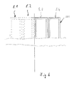
- Fig. 3 shows the radiator 1 from the side, ie with a view of a side surface 17 and narrow side of the network 2.
- the air flow direction is indicated by an arrow L.
- the air thus initially enters the net 2 via an end face 18 and exits the net 2 via the end face 7.
- the grid 8 is arranged at a small distance and parallel to the end face 7.
- the PTC heating elements 9 are located at approximately uniform intervals, ie the PTC elements have a height which corresponds to the spacing between the grid 8 and the end face 7. This distance is about 2 to 5 mm.
- the connector box 12 is located laterally next to the actual water tank 4 and is connected to the water tank via a common circumferential flange 4a.
- a detail X is indicated by dashed lines and will be described below.
- FIG. 4 shows this detail X from FIG. 3, ie essentially the connection of a PTC heating element 9 with the grid 8 and the net 2, which is shown as a cutout between the air inlet side end face 18 and the air outlet side end face 7. It consists of mutually parallel, substantially planar ribs 6, which are penetrated by two legs 5a, 5b of the pipe fork 5 (see FIG. Ribs 6 and tubes 5a, 5b are mechanically joined, ie, for example, by widening of the tubes 5a, 5b connected to the ribs 6.
- the ribs are made of aluminum, are relatively thin and have a small distance from each other on or a high rib density, which is approximately in the range of 50 to 60 ribs per dm
- the ribs 6 end side end edges 6a, the total respectively the end faces 7 and Form 18 and the plane of the end faces 7, 18 span.
- a thin layer 19 of a first compound material, preferably an electrically conductive adhesive is arranged between the PTC element 9 and the grid 8.
- the PTC element 9 is preferably cuboid and has approximately the dimension 8 x 32 x 1.4 mm. Between grid 8 and end face 7 there is a distance a, which corresponds approximately to the height of the PTC elements, in this case about 1.4 mm. The length of 32 mm extends in the direction of the tubes 5a, 5b.
- the PTC element 9 rests on the end face 7, wherein here the rib ends 6a are deformed to approximately rib ends 6b bent at right angles.
- a second layer 20 of a bonding material is arranged, which also consists of an electrically conductive adhesive. On the one hand an improved mechanical connection and on the other hand a good electrical conductivity is produced.
- the auxiliary heater When the auxiliary heater is switched on, therefore, current flows from the grid 8 (positive pole) via the connecting layer 19 into the PTC element 9 and via the second layer 20 into the ribs 6. From there, the current flows via the metallic contact with the tubes 5a, 5b the tube bottom 3, not shown here, at which the contact tongue 13 for the negative terminal or ground terminal is located.
- an insulating 101 for electrical insulation of the grid 8 from the network 2 is present.
- the insulating frame ensures a constant distance a between the grid 8 and the network 2. The insulating frame ensures that even with a mechanical deformation of the network, which may occur for example by mounting, storage or transport of the radiator, a short circuit is avoided ,
- the network 2 of a round tubular heater shown here corresponds to a standard version, which is also used without additional heating.
- the network 2 must therefore in no way to the additional heating in the form of the grid 3 with adapted to the PTC elements 9. Rather, the grid 8, on which the PTC elements 9 already fastened by the adhesive layer 19 are placed under slight pressure on the face 7, so that the Push PTC elements 9 in the end face 7 and thus the deformation cause the rib ends to angled rib ends 6b. It can the second layer 20 may already be applied to the PTC elements 9, so that the rib ends 6b "dig" into this layer 20 and thus to make a very good mechanical and electrical connection.
- the Grid 8 is dimensioned to take into account the support points has a sufficient bending stiffness by the PTC elements 9, so that contact between grid 8 and end face 7 or ribs. 6 safely avoided. Such a "sagging" or sagging of the Grating is complicated by the relatively short distances of the PTC elements. On the other hand, the grid 8 should also be relatively "open” in order to maximize one to produce low pressure drop for the air.
- Fig. 5 shows a plan view of the heater 1, that is, on the air outlet side end face 7 with grating 8.
- this grid 8 is divided into four zones 8.1, 8.2, 8.3, subdivided 8.4, each individually and independently heated or are energized.
- the individual PTC elements 9 can be arranged according to different patterns - here the PTC elements are arranged in a zig-zag shape, which is indicated by a dashed line 21. Furthermore, the course of the pipe legs 5a of the pipe forks 5 is shown by dashed lines. It is also possible, in deviation from the representation in FIG. 5, to arrange the PTC elements 9 between two tubes 5a, ie in a grid strip of the width b.
- the air heated by the PTC elements 9 would also hit the pipes and thus heat the coolant, which is not desirable in the case of pure auxiliary heating. Rather, only the air should be heated, because a faster and more effective heating effect for heating the passenger compartment is achieved.
- a detail Y is indicated by dashed lines and will be described below.
- FIG. 6 shows this detail Y of FIG. 5, ie an insulating frame 101 which is arranged between grid 8 and net 2, wherein in the illustrated embodiment the insulating frame 101 is made up of a plurality of insulating frame parts, each between one of the zones 8.1, 8.2, 8.3, 8.4 of the grid 8 and the network 2 are arranged to minimize a short circuit risk.
- the insulating frame 101 thus ensures electrical insulation and a defined distance between the grid 8 and the network. 2
- the additional heater according to the invention was exemplified by a mechanical joined round tubular heater explained, for this type of additional heating is extremely beneficial.
- the inventive Additional heating in the form of a grid with PTC elements also for other network construction, z. B. soldered nets, which are usually made Flat tubes and corrugated fins exist find application. in principle can the PTC elements in the same way - as described above - z. B. be connected by adhesive with the corrugated fins. It is also possible To solder the PTC elements with the corrugated fins, which simultaneously with the Soldering of the radiator block including tube bottom can be done. Of the Plastic water tank will be after the soldering process - as known - connected by a flare and rubber seal with the tube sheet.
- this type of booster heater for the common Structures of radiator networks is usable, without the Nets changed or adapted to their design without additional heating would have to be.
Landscapes
- Engineering & Computer Science (AREA)
- Physics & Mathematics (AREA)
- Thermal Sciences (AREA)
- Mechanical Engineering (AREA)
- Chemical & Material Sciences (AREA)
- Combustion & Propulsion (AREA)
- General Engineering & Computer Science (AREA)
- Air-Conditioning For Vehicles (AREA)
- Resistance Heating (AREA)
Abstract
Description
Die Erfindung betrifft einen Heizkörper für Kraftfahrzeuge mit integrierter
elektrischer Zusatzheizung nach dem Oberbegriff des Patentanspruches 1,
bekannt durch EP-B 0 707 434.The invention relates to a radiator for motor vehicles with integrated
electric auxiliary heater according to the preamble of
Kraftfahrzeuge mit verbrauchsoptimierten Motoren, z. B. Dieselmotoren, benötigen heute vielfach eine Zusatzheizung, um die aufgrund des hohen thermischen Wirkungsgrades fehlende Heizleistung zu kompensieren. Bei diesen Zusatzheizungen, so genannten Zuheizern, haben sich insbesondere elektrische Heizungen durchgesetzt, die ihre elektrische Energie aus dem Bordnetz des Kraftfahrzeuges beziehen. Zu unterscheiden sind dabei unabhängige Zuheizer mit elektrischer Widerstandsheizung und integrierte Systeme, bei denen die elektrische Zusatzheizung in den Heizkörper einer Heizungsanlage integriert ist.Motor vehicles with consumption-optimized engines, eg. As diesel engines require today often a supplementary heating, due to the high thermal efficiency to compensate for lack of heating power. at These auxiliary heaters, so-called auxiliary heaters, have become particularly electrical heaters enforced their electrical energy from the Get electrical system of the motor vehicle. To distinguish are independent Heater with electrical resistance heating and integrated systems, where the electric auxiliary heater in the radiator of a heating system is integrated.
Durch die DE-A 199 11 547 und die DE-A 199 57 452 wurden solche unabhängigen Zuheizer bekannt, welche aus einem Register von Heizelementen bestehen, welche von Umgebungsluft überströmt werden, die dann in den Fahrzeuginnenraum geleitet wird. Die Erwärmung der Luft erfolgt über elektrisch beheizte PTC-Elemente, die bei steigender Temperatur ihren Widerstand erhöhen und somit selbstregelnd sind. Derartige Heizregister bedeuten ein zusätzliches Teil, welches in der Heizungsanlage des Kraftfahrzeuges untergebracht werden muss. By DE-A 199 11 547 and DE-A 199 57 452 were such independent Heater known, which consists of a register of heating elements exist, which are covered by ambient air, which then in the Vehicle interior is passed. The heating of the air via electrical heated PTC elements, their resistance as the temperature rises increase and thus are self-regulating. Such heating registers mean an additional part, which in the heating system of the motor vehicle must be accommodated.
Man hat daher vorgeschlagen - wie durch die DE-A 44 33 814 bekannt wurde - die elektrischen Heizelemente rohrförmig auszubilden und in einen Heizkörper zu integrieren, wobei die Rohre innen von Kühlmittel durchströmt und von außen durch PTC-Elemente beheizt werden. Durch diese Lösung ergibt sich nicht nur eine Zusatzheizung für die Luft, sondern auch eine Vorwärmung des Kühlmittels in der Warmlaufphase, was bei einer Zusatzheizung nicht immer erwünscht ist.It has therefore been proposed - as was known from DE-A 44 33 814 - Form the electric heating elements tubular and in a Integrate radiator, wherein the tubes flows through the inside of coolant and externally heated by PTC elements. Through this solution not only gives an additional heating for the air, but also a preheating the coolant in the warm-up phase, which in an additional heating not always wanted.
Nach der DE-A 198 35 229 und der DE-A 198 11 629 wurden integrierte Systeme bekannt, bei welchen die Heizelemente nicht die Rohre und damit das Kühlmittel beheizen - es handelt sich vielmehr um "Blindrohre", die ihre Wärme nur nach außen an Rippen des Heizkörpers abgeben und somit die Luft erwärmen. Der Heizkörper besteht dabei aus einem Netz mit Flachrohren und Wellrippen, die miteinander verlötet sind. Nachteilig bei diesen integrierten Zusatzheizungen ist, dass der Heizkörperblock bzw. das Netz zunächst gelötet wird und dass im Anschluss an den Lötprozess die Heizelemente in entsprechende Lücken des Netzes eingesetzt werden.According to DE-A 198 35 229 and DE-A 198 11 629 were integrated systems known, in which the heating elements not the pipes and thus the Heat coolant - it is rather to "blind tubes" that their Heat only to the outside on ribs of the radiator and thus give the Warm the air. The radiator consists of a network with flat tubes and corrugated ribs that are soldered together. A disadvantage of these integrated Additional heaters is that the radiator block or the network first is soldered and that after the soldering process, the heating elements be used in corresponding gaps in the network.
Durch die EP-B 0 707 434 wurde ein Heizkörper mit einer integrierten elektrischen Zusatzheizung in Form von PTC-Heizrohren bekannt, und zwar mit einem Netz bzw. Rohr-/Rippen-Block, der sowohl gelötet als auch mechanisch gefügt ist. Mechanisch gefügt heißt in diesem Fall, dass Rohre und Rippen des Heizkörpers - ohne Löten - zu einem in sich festen Block gefügt werden, z. B. durch Aufweiten der Rohre innerhalb von Öffnungen in den Rippen. Bei dieser Zusatzheizung sind die Heizrohre als Flachrohre oder als flachovale, aufweitbare Rohre ausgebildet, d. h. mit einem länglichen Querschnitt, in welchem ebenfalls flach ausgebildete PTC-Heizelemente mittels eines Kunststoffrahmens angeordnet sind. Dieses integrierte System ist auf flache bzw. flachovale Rohrquerschnitte beschränkt, in denen die Heizelemente untergebraucht werden können. Insofern ist dieses bekannte System nicht auf alle Heizköperbauweisen, z. B. mechanisch gefertigte Rundrohrheizkörper anwendbar.By EP-B 0 707 434 a radiator with an integrated electrical Additional heating in the form of PTC heating pipes known, with a mesh or tube / rib block, both soldered and mechanical is added. Mechanically joined in this case means that pipes and Ripping the radiator - without soldering - joined into a solid block be, for. B. by widening the tubes within openings in the Ribs. In this additional heating, the heating tubes are flat tubes or as flat oval, expandable tubes formed, d. H. with an elongated cross section, in which also flat trained PTC heating elements by means a plastic frame are arranged. This integrated system is on limited flat or oval tube cross-sections, in which the heating elements can be used. In this respect, this is known system not on all Heizköperbauweisen, z. B. mechanically manufactured tubular heating elements applicable.
Es ist daher Aufgabe der vorliegenden Erfindung, einen Heizkörper der eingangs genannten Art dahingehend zu verbessern, dass er eine möglichst universell verwendbare Zusatzheizung aufweist, die möglichst ohne bauliche Veränderungen in den Heizkörper integrierbar ist.It is therefore an object of the present invention, a radiator of the above mentioned type to improve that he as possible having universally usable auxiliary heating, the possible without structural Changes in the radiator can be integrated.
Diese Aufgabe wird durch die Merkmale des Patentanspruches 1 gelöst. Erfindungsgemäß
sind die Heizelemente auf einer Stirnfläche des Heizkörpers,
insbesondere auf dessen Luftaustrittsseite angeordnet und durch ein elektrisch
leitendes Gitter am Heizkörper befestigt. Die vorzugsweise als PTC-Elemente
ausgebildeten Heizelemente sind gleichmäßig über die Stirnfläche
verteilt und stehen in wärmeleitendem Kontakt mit den Rippen des Heizkörpers,
sodass die von den PTC-Elementen infolge Stromdurchfluss erzeugte
Wärme in die Rippen geleitet und von dort auf die Luft übertragen wird. Das
Gitter ist an eine Stromversorgung angeschlossen und steht in elektrisch
leitender Verbindung mit den PTC-Elementen. Das Gitter kann als Zusatzteil
für den Heizkörper hergestellt und mit einfachen Mitteln am Heizkörper in der
Weise befestigt werden, dass die einzelnen PTC-Elemente auf die Stirnfläche
des Heizkörpers gepresst und somit gehalten werden. Der Vorteil dieser
integrierten Zusatzheizung besteht darin, dass sie ohne weiteres an bestehenden,
serienmäßigen Heizkörpern der verschiedensten Bauweisen angebracht
werden kann, ohne dass wesentliche Veränderungen an diesen Heizkörpern
vorgenommen werden müssen. Insbesondere braucht das Netz des
Heizkörpers, welches aus Rohren und Rippen besteht, nicht verändert zu
werden, was einerseits einen wärmetechnischen und andererseits einen erheblichen
kostenmäßigen Vorteil bedeutet. Das Netz des Heizkörpers kann
also sowohl gelötet als auch mechanisch gefügt sein. Die Rohre können als
Flachrohre mit Wellrippen oder als aufweitbare Oval- oder Rundrohre mit
flachen Rippen ausgebildet sein. In jedem Falle wird die Stirnfläche des
Heizkörpers durch Stirnkanten der Wellrippen gebildet, welche in wärmeleitenden
und elektrischen Kontakt mit den PTC-Elementen gebracht werden
können. Dadurch ist in jedem Falle eine Wärmeleitung und ein Stromdurchfluss
gewährleistet.This object is solved by the features of
In vorteilhafter Ausgestaltung der Erfindung werden die PTC-Elemente in die Stirnflächen des Heizkörpers eingedrückt, wobei die Rippen bzw. ihre Stirnkanten im Bereich der PTC-Elemente verformt bzw. umgebogen werden. In an advantageous embodiment of the invention, the PTC elements in the Pressed end faces of the radiator, wherein the ribs or their end edges deformed or bent in the area of the PTC elements.
Dadurch ergibt sich der Vorteil einer besseren Halterung und eines verbesserten thermischen Kontaktes, d. h. eine verbesserte Wärmeleitung.This results in the advantage of better support and improved thermal contact, d. H. an improved heat conduction.
In einer Weiterbildung der Erfindung ist zwischen dem Gitter und den PTC-Elementen ein Verbindungsmaterial angeordnet. Dadurch wird die mechanische Verbindung und der elektrische Kontakt zwischen PTC-Elementen und dem Gitter verbessert. Das Verbindungsmaterial kann beispielsweise ein Silikonkleber sein, mit dem die PTC-Elemente auf dem Gitter befestigt werden. Die PTC-Elemente können somit vorher auf dem Gitter positioniert und aufgeklebt werden, sodass das Gitter mit den Heizelementen als vorgefertigtes Teil mit dem Heizkörper montiert werden kann.In one embodiment of the invention is between the grid and the PTC elements arranged a connecting material. This will make the mechanical Connection and electrical contact between PTC elements and improved the grid. The connecting material may, for example, a Silicone adhesive, with which the PTC elements are attached to the grid. The PTC elements can thus previously positioned on the grid and be glued so that the grid with the heating elements as prefabricated Part can be mounted with the radiator.
In vorteilhafter Weiterbildung der Erfindung ist auch zwischen den PTC-Elementen und der Stirnfläche des Heizkörpers ein Verbindungsmaterial angeordnet, welches einerseits die Haftung und andererseits die Wärmeleitung sowie die elektrische Leitfähigkeit verbessert. Dieses Verbindungsmaterial kann ebenso ein Silikonkleber sein, was insbesondere bei verformten Rippenenden, die sich zu einer Fläche umlegen, vorteilhaft sein kann. Andererseits können die PTC-Elemente auch mit den Rippen verlötet sein, wenn es sich um ein gelötetes Netz handelt. Dadurch ergibt sich eine sehr gute mechanische Verbindung sowie eine hohe Wärmeleitfähigkeit.In an advantageous embodiment of the invention is also between the PTC elements and the end face of the radiator arranged a connecting material, which on the one hand the adhesion and on the other hand the heat conduction and improves the electrical conductivity. This connecting material may also be a silicone adhesive, which is especially true for deformed rib ends, which can turn into a surface, may be advantageous. on the other hand The PTC elements can also be soldered to the ribs if it is is a soldered network. This results in a very good mechanical Compound as well as a high thermal conductivity.
In vorteilhafter Weiterbildung der Erfindung kann das Gitter aus einem Drahtgeflecht oder auch aus einem gestanzten Blech aus Messing, Aluminium oder Kupfer, d. h. mit guter elektrischer Leitfähigkeit bestehen. Für beide Ausbildungen ist es vorteilhaft, wenn das Gitter eine hohe Biegesteifigkeit aufweist, sodass eine Berührung zwischen Gitter und Stirnfläche zur Vermeidung eines Kurzschlusses sicher vermieden wird.In an advantageous embodiment of the invention, the grid of a Wire mesh or also from a stamped sheet metal made of brass, aluminum or copper, d. H. exist with good electrical conductivity. For both Training it is advantageous if the grid has a high bending stiffness so as to avoid contact between grid and face a short circuit is safely avoided.
Nach einer weiteren vorteilhaften Ausgestaltung der Erfindung ist das Gitter in einzlene Zonen unterteilt, die als Streifen ausgebildet und parallel zueinander angeordnet sind, d. h. parallel zum Verlauf der Rohre des Heizkörpers. Dadurch ist es möglich, nur einzelne Zonen zu beheizen und damit die Heizleistung der Zusatzheizung zu variieren bzw. dem Bedarf anzupassen. Die Stromzuführungen für die einzelnen Zonen werden in einem Steckerkasten, der mit dem Heizkörper integriert sein kann, zusammengeführt. Vorteilhafterweise sind die Rippen des Heizkörpers mit einem Minuskontakt, d. h. mit der Masse des Kraftfahrzeuges verbunden.According to a further advantageous embodiment of the invention, the grid subdivided into individual zones, which are formed as strips and parallel to each other are arranged, d. H. parallel to the course of the tubes of the radiator. This makes it possible to heat only individual zones and thus the To vary the heating capacity of the additional heating or adapt to the needs. The power supply for the individual zones are in a connector box, which can be integrated with the radiator, merged. advantageously, are the ribs of the radiator with a negative contact, d. H. connected to the mass of the motor vehicle.
Nach einer weiteren vorteilhaften Ausgestaltung sind die PTC-Elemente etwa gleichmäßig über die Stirnfläche verteilt, z. B. in einer zick-zack-förmigen Anordnung, d. h. in Richtung der Rohre gesehen jeweils versetzt. Es kann jedoch auch vorteilhaft sein, die PTC-Elemente in einer Reihe und zwischen jeweils zwei Rohrreihen anzuordnen. Dadurch wird eine Wärmeleitung in die Rippenbereiche zwischen den Heizungsrohren bewirkt, d. h. die Wärme fließt vornehmlich in die Rippen und wird damit an die Luft und nicht an die Rohre bzw. das durch die Rohre fließende Kühlmittel übertragen, was nicht erwünscht ist. Durch die gleichmäßige Verteilung der Heizelemente über die gesamte Stirnfläche wird auch Heizleistung eingespart, da die durch den Heizkörper strömende Luft gleichmäßig erwärmt wird und nicht - wie beim Stand der Technik - nur in einzelnen konzentrierten Bereichen. Insgesamt bietet diese integrierte Zusatzheizung gegenüber dem Stand der Technik Gewichts- und Kostenvorteile und ist darüber hinaus universell verwendbar.According to a further advantageous embodiment, the PTC elements are approximately evenly distributed over the face, z. B. in a zigzag-shaped Arrangement, d. H. each offset in the direction of the tubes. It can However, it may also be advantageous to place the PTC elements in a row and between each to arrange two rows of tubes. This will cause a heat conduction in the Rib areas between the heating pipes causes, d. H. the heat flows primarily into the ribs and is thus to the air and not to the Do not pass pipes or the coolant flowing through the pipes is desired. Due to the even distribution of the heating elements over the entire face is also saved heating power, as by the Radiator flowing air is heated evenly and not - as in the State of the art - only in individual concentrated areas. A total of offers this integrated auxiliary heater over the prior art Weight and cost advantages and is also universally applicable.
Ein Ausführungsbeispiel der Erfindung ist in der Zeichnung dargestellt und wird im Folgenden näher beschrieben. Es zeigen
- Fig. 1
- eine perspektivische Ansicht eines Heizkörpers mit Gitter,
- Fig. 2
- eine weitere perspektivische Ansicht des Heizkörpers aus anderer Richtung,
- Fig. 3
- eine Seitenansicht des Heizkörpers,
- Fig. 4
- eine Einzelheit X aus Fig. 3,
- Fig. 5
- eine Draufsicht auf den Heizkörper und das Gitter und
- Fig. 6
- eine Einzelheit Y aus Fig. 5.
- Fig. 1
- a perspective view of a radiator with grid,
- Fig. 2
- another perspective view of the radiator from another direction,
- Fig. 3
- a side view of the radiator,
- Fig. 4
- a detail X of Fig. 3,
- Fig. 5
- a plan view of the radiator and the grid and
- Fig. 6
- a detail Y of FIG. 5.
Fig. 1 zeigt einen mechanisch gefügten Rundrohr-Heizkörper 1 mit einem
Heizkörpernetz 2, einem Rohrboden 3 und einem Wasserkasten 4, der aus
Kunststoff hergestellt ist. Das Netz 2 weist Rundrohre auf, von denen lediglich
Rohrbögen 5 erkennbar sind. Jeder Rohrbogen 5 ist Teil einer nicht
sichtbaren Rohrgabel, deren Enden im Rohrboden 3 befestigt und abgedichtet
sind. Die Rohrgabeln mit den Rohrbögen 5 stecken in Rippen, von
denen die unterste, d. d. die dem Rohrboden 3 abgewandte mit der Bezugsziffer
6 versehen ist. Rohre und Rippen sind mechanisch gefügt (ohne Löten)
und bilden das Netz 2. Letzteres weist eine in der Zeichnung oben liegende
Stirnfläche 7 auf, die durch ein Gitter 8, bestehend aus vier Zonen 8.1, 8.2,
8.3, 8.4, abgedeckt ist. Unterhalb des Gitters 8 und oberhalb der Stirnfläche
7 sind (etwas schwach erkennbar) rechteckige PTC-Elemente 9, gleichmäßig
über die Stirnfläche 7 verteilt, angeordnet. Die Gitterzonen 8.1 bis 8.4
sind als metallische gestanzte Streifen aus Messing- oder Aluminiumblech
hergestellt und stirnseitig mit einem elektrischen Anschlussteil 10 verbunden.
An die Anschlussteile 10 schließen sich jeweils streifenförmige Leiter 11 an,
die in einen am Wasserkasten 4 angeordneten Steckerkasten 12 münden.
Die Leiter 11 sind im Steckerkasten mit einem nicht dargestellten Stromversorgungskabel
verbunden, welches aus dem nicht dargestellten Bordnetz
(Pluspol) des Kraftfahrzeuges versorgt wird. Am Rohrboden 3, der in metallischem
und damit elektrisch leitenden Kontakt mit den Rippen 6 steht, ist an
der Schmalseite eine Kontaktfahne 13 angeordnet, die durch eine Öffnung
im Kunststoffwasserkasten 4 nach außen geführt ist. Diese Kontaktfahne 13
bildet den Minuspol und wird an Masse angeschlossen. Fig. 1 shows a mechanically joined round
Fig. 2 zeigt eine weitere perspektivische Ansicht des Rundrohrheizkörpers 1
mit Blick auf den Wasserkasten 4, welcher einen Eintrittsstutzen 15 und einen
Austrittsstutzen 16 für ein flüssiges Wärmeträgermedium aufweist. Der
Heizkörper 1 ist über diese beiden Stutzen 15, 16 an einen nicht dargestellten
Kühlmittelkreislauf einer Brennkraftmaschine des Kraftfahrzeuges angeschlossen.
Im Wasserkasten 4 befindet sich - nicht sichtbar - eine
Längstrennwand, die den Wasserkasten in eine nicht dargestellte
Eintritts- und eine Austrittskammer unterteilt. Letztere stehen mit den Schenkeln der
Rohrgabeln 5 in Verbindung, sodass der Heizkörper vom Kühlmittel zweimal
durchströmt wird, einmal auf der Vorderseite und einmal auf der Rückseite
bzw. - je nach Einbau - umgekehrt. Der Steckerkasten 12 ist größtenteils
einstückig mit dem Wasserkasten 4 verbunden, d. h. ebenfalls aus Kunststoff
gespritzt. Ledigleich ein Deckel 14 ist als separates Teil ausgebildet und
wird nach der Montage des nicht dargestellten Stromanschlusskabels auf
den Steckerkasten 12 aufgesetzt und mit diesem verclipst. Der gesamte
Heizkörper 1 wird - wie bekannt - in eine Heizungs- oder Klimaanlage eines
Kraftfahrzeuges in einen nicht dargestellten Luftströmungskanal eingebaut
und dort von Luft durchströmt. Der Heizkörper 1 wird vorzugsweise so eingebaut,
dass sich das Gitter 8 auf der Luftaustrittsseite befindet. Die sich
daraus ergebenden Vorteile werden unten erläutert. 2 shows another perspective view of the round
Fig. 3 zeigt den Heizkörper 1 von der Seite, d. h. mit Blick auf eine Seitenfläche
17 bzw. Schmalseite des Netzes 2. Die Luftströmungsrichtung ist mit
einem Pfeil L gekennzeichnet. Die Luft tritt also zunächst über eine Stirnfläche
18 in das Netz 2 ein und tritt über die Stirnfläche 7 aus dem Netz 2 aus.
In der Zeichnung oberhalb der Stirnfläche 7 ist das Gitter 8 mit einem geringen
Abstand und parallel zur Stirnfläche 7 angeordnet. Zwischen dem Gitter
8 und der Stirnfläche 7 befinden sich in etwa gleichmäßigen Abständen die
PTC-Heizelemente 9, d. h. die PTC-Elemente weisen eine Höhe auf, die
dem Abstand zwischen Gitter 8 und Stirnfläche 7 entspricht. Dieser Abstand
beträgt etwa 2 bis 5 mm. Im Übrigen erkennt man aus dieser Seitenansicht
deutlich die Ausbildung der Kontaktfahne 13 und ihre einstückige Verbindung
mit dem metallischen Rohrboden 3. Der Steckerkasten 12 befindet sich
seitlich neben dem eigentlichen Wasserkasten 4 und ist mit dem Wasserkasten
über einen gemeinsamen umlaufenden Flansch 4a verbunden. Eine
Einzelheit X ist durch gestrichelte Linien gekennzeichnet und wird im Folgenden
beschrieben. Fig. 3 shows the
Fig. 4 zeigt diese Einzelheit X aus Fig. 3, d. h. im Wesentlichen die Verbindung
eines PTC-Heizelementes 9 mit dem Gitter 8 und dem Netz 2, welches
als Ausschnitt zwischen lufteinstrittseitiger Stirnfläche 18 und luftaustrittsseitiger
Stirnfläche 7 dargestellt ist. Es besteht aus parallel zueinander angeordneten,
im Wesentlichen eben ausgebildeten Rippen 6, die von zwei
Schenkeln 5a, 5b der Rohrgabel 5 (vgl. Fig. 1) durchsetzt werden. Rippen 6
und Rohre 5a, 5b sind mechanisch gefügt, d. h. z. B. durch Aufweitung der
Rohre 5a, 5b mit den Rippen 6 verbunden. Die Rippen bestehen aus Aluminium,
sind relativ dünn und weisen einen geringen Abstand zueinander auf
bzw. eine hohe Rippendichte, die etwa im Bereich von 50 bis 60 Rippen pro
dm liegt Die Rippen 6 weisen endseitig Stirnkanten 6a auf, die insgesamt
jeweils die Stirnflächen 7 und 18 bilden bzw. die Ebene der Stirnflächen 7,
18 aufspannen. Zwischen dem PTC-Element 9 und dem Gitter 8 ist eine
dünne Schicht 19 aus einem ersten Verbindungsmaterial, vorzugsweise einem
elektrisch leitenden Kleber angeordnet. Durch diese Kleberschicht 19
werden die PTC-Elemente 9 einerseits mit dem Gitter 8 mechanisch verbunden
- andererseits wird damit ein guter elektrisch leitender Kontakt zwischen
dem Gitter 8 und dem PTC-Element 9 hergestellt. Das PTC-Element 9 ist
vorzugsweise quaderförmig ausgebildet und weist etwa die Abmessung 8 x
32 x 1,4 mm auf. Zwischen Gitter 8 und Stirnfläche 7 besteht ein Abstand a,
der etwa der Höhe der PTC-Elemente entspricht, hier also ca. 1,4 mm. Die
Länge von 32 mm erstreckt sich in Richtung der Rohre 5a, 5b. Das PTC-Element
9 liegt andererseits auf der Stirnfläche 7 auf, wobei hier die Rippenenden
6a zu etwa rechtwinklig abgebogenen Rippenenden 6b verformt
sind. Im Bereich dieser abgewinkelten Rippenenden 6b ist eine zweite
Schicht 20 aus einem Verbindungsmaterial angeordnet, die ebenfalls aus
einem elektrisch leitfähigen Kleber besteht. Damit wird einerseits eine verbesserte
mechanische Verbindung und andererseits eine gute elektrische
Leitfähigkeit hergestellt. Bei Einschaltung der Zusatzheizung fließt also
Strom vom Gitter 8 (Pluspol) über die Verbindungsschicht 19 in das PTC-Element
9 und über die zweite Schicht 20 in die Rippen 6. Von dort fließt der
Strom über den metallischen Kontakt mit den Rohren 5a, 5b in den hier nicht
dargestellten Rohrboden 3, an welchem sich die Kontaktzunge 13 für den
Minuspol bzw. Masseanschluss befindet. Zusätzlich ist im dargestellten
Ausführungsbeispiel ein Isolierrahmen 101 zur elektrischen Isolierung des
Gitters 8 vom Netz 2 vorhanden. Zudem sorgt der Isolierrahmen für einen
gleichbleibenden Abstand a zwischen dem Gitter 8 und dem Netz 2. Durch
den Isolierrahmen wird sichergestellt, dass auch bei einer mechanischen
Verformung des Netzes, die beispielsweise durch Montage, Lagerung oder
Transport des Heizkörpers auftreten können, ein Kurzschluß vermieden wird. FIG. 4 shows this detail X from FIG. 3, ie essentially the connection of a
Das hier dargestellte Netz 2 eines Rundrohrheizkörpers entspricht einer Serienausführung,
die auch ohne Zusatzheizung Verwendung findet. Das Netz
2 muss somit in keiner Weise an die Zusatzheizung in Form des Gitters 3 mit
dem PTC-Elemtenen 9 angepasst werden. Vielmehr wird das Gitter 8, an
welchen die PTC-Elemente 9 bereits durch die Klebeschicht 19 befestigt
sind, unter leichtem Druck auf die Stirnfläche 7 aufgelegt, sodass sich die
PTC-Elemente 9 in die Stirnfläche 7 eindrücken und damit die Verformung
der Rippenenden zu abgewinkelten Rippenenden 6b bewirken. Dabei kann
die zweite Schicht 20 bereits auf die PTC-Elemente 9 aufgetragen sein, sodass
sich die Rippenenden 6b in diese Schicht 20 "eingraben" und damit
eine sehr gute mechanische und elektrische Verbindung herstellen. Das
Gitter 8 ist so dimensioniert, dass es unter Berücksichtigung der Abstützpunkte
durch die PTC-Elemente 9 eine hinreichende Biegesteifigkeit aufweist,
damit ein Kontakt zwischen Gitter 8 und Stirnfläche 7 bzw. Rippen 6
sicher vermieden wird. Ein solches "Durchhängen" oder Durchbiegen des
Gitters wird durch die relativ kurzen Abstände der PTC-Elemente erschwert.
Andererseits soll das Gitter 8 auch relativ "offen" sein, um einen möglichst
geringen Druckabfall für die Luft zu erzeugen.The
Fig. 5 zeigt eine Draufsicht auf den Heizkörper 1, d. h. auf die luftaustrittsseitige
Stirnfläche 7 mit Gitter 8. Wie bereits oben erwähnt, ist dieses Gitter 8
in vier Zonen 8.1, 8.2, 8.3, 8.4 unterteilt, die jeweils einzeln und unabhängig
voneinander beheizbar bzw. bestrombar sind. Die einzelnen PTC-Elemente
9 können nach unterschiedlichen Mustern angeordnet werden - hier sind die
PTC-Elemente zick-zack-förmig angeordnet, was durch eine gestrichelte Linie
21 angedeutet ist. Ferner ist durch gestrichelte Linien der Verlauf der
Rohrschenkel 5a der Rohrgabeln 5 dargestellt. Es ist auch möglich, in Abweichung
der Darstellung in Fig. 5 die PTC-Elemente 9 zwischen zwei Rohre
5a, d. h. in einem Gitterstreifen der Breite b anzuordnen. Der von den PTC-Elementen
9 ausgehende Wärmeeintrag in die Rippen 6 verläuft dann zwischen
den Rohren 5a hindurch und wird dadurch in erster Linie an die Luft
abgegeben und weniger an das Kühlmittel, welches die Rohre 5a durchströmt.
Der gleiche Gesichtspunkt gilt für die Anordnung der PTC-Elemente
9 bzw. des Gitters 8 auf der Luftaustrittsseite, d. h. der Stirnfläche 7 des
Heizkörpers 1. Bei einer umgekehrten Anordnung würde die durch die PTC-Elemente
9 erwärmte Luft auch auf die Rohre treffen und damit das Kühlmittel
erwärmen, was im Falle einer reinen Zusatzheizung nicht erwünscht
ist. Vielmehr soll nur die Luft erwärmt werden, weil dadurch eine schnellere
und effektivere Heizwirkung zur Beheizung des Fahrgastraumes erzielt wird.
Eine Einzelheit Y ist durch gestrichelte Linien gekennzeichnet und wird im
Folgenden beschrieben. Fig. 5 shows a plan view of the
Fig. 6 zeigt diese Einzelheit Y aus Fig. 5, d. h. einen Isolierrahmen 101, der
zwischen Gitter 8 und Netz 2 angeordnet ist, wobei im dargestellten Ausführungsbeispiel
der Isolierrahmen 101 aus mehreren Isolierrahmenteilen aufgebaut
ist, die jeweils zwischen einer der Zonen 8.1, 8.2, 8.3, 8.4 des Gitters
8 und dem Netz 2 angeordnet sind, um ein Kurzschlußrisiko zu minimieren.
Der Isolierrahmen 101 sorgt also für eine elektrische Isolation und einen
festgelegten Abstand zwischen dem Gitter 8 und dem Netz 2. 6 shows this detail Y of FIG. 5, ie an insulating
Die erfindungsgemäße Zusatzheizung wurde beispielhaft anhand eines mechanisch gefügten Rundrohrheizkörpers erläutert, für den diese Art der Zusatzheizung außerordentlich vorteilhaft ist. Andererseits kann die erfindungsgemäße Zusatzheizung in Form eines Gitters mit PTC-Elementen auch für andere Netzbauweisen, z. B. gelötete Netze, die in der Regel aus Flachrohren und Wellrippen bestehen, Anwendung finden. Grundsätzlich können die PTC-Elemente in gleicher Weise - wie oben beschrieben - z. B. durch Kleber mit den Wellrippen verbunden werden. Möglich ist jedoch auch, die PTC-Elemente mit den Wellrippen zu verlöten, was gleichzeitig mit dem Verlöten des Heizkörperblockes einschließlich Rohrboden erfolgen kann. Der Wasserkasten aus Kunststoff wird nach dem Lötprozess - wie bekannt - durch eine Bördelverbindung und Gummidichtung mit dem Rohrboden verbunden. Somit zeigt sich, dass diese Art der Zusatzheizung für die gängigen Bauweisen von Heizkörpernetzen verwendbar ist, und zwar ohne dass die Netze gegenüber ihrer Ausführung ohne Zusatzheizung verändert oder angepasst werden müssten.The additional heater according to the invention was exemplified by a mechanical joined round tubular heater explained, for this type of additional heating is extremely beneficial. On the other hand, the inventive Additional heating in the form of a grid with PTC elements also for other network construction, z. B. soldered nets, which are usually made Flat tubes and corrugated fins exist, find application. in principle can the PTC elements in the same way - as described above - z. B. be connected by adhesive with the corrugated fins. It is also possible To solder the PTC elements with the corrugated fins, which simultaneously with the Soldering of the radiator block including tube bottom can be done. Of the Plastic water tank will be after the soldering process - as known - connected by a flare and rubber seal with the tube sheet. Thus, it turns out that this type of booster heater for the common Structures of radiator networks is usable, without the Nets changed or adapted to their design without additional heating would have to be.
Claims (23)
Priority Applications (3)
| Application Number | Priority Date | Filing Date | Title |
|---|---|---|---|
| AT03290620T ATE366676T1 (en) | 2003-03-12 | 2003-03-12 | RADIATOR WITH INTEGRATED ADDITIONAL ELECTRIC HEATING |
| EP03290620A EP1457368B1 (en) | 2003-03-12 | 2003-03-12 | Heat exchanger with integrated electric supplementary heating |
| DE50307647T DE50307647D1 (en) | 2003-03-12 | 2003-03-12 | Radiator with integrated electric heater |
Applications Claiming Priority (1)
| Application Number | Priority Date | Filing Date | Title |
|---|---|---|---|
| EP03290620A EP1457368B1 (en) | 2003-03-12 | 2003-03-12 | Heat exchanger with integrated electric supplementary heating |
Publications (2)
| Publication Number | Publication Date |
|---|---|
| EP1457368A1 true EP1457368A1 (en) | 2004-09-15 |
| EP1457368B1 EP1457368B1 (en) | 2007-07-11 |
Family
ID=32749011
Family Applications (1)
| Application Number | Title | Priority Date | Filing Date |
|---|---|---|---|
| EP03290620A Expired - Lifetime EP1457368B1 (en) | 2003-03-12 | 2003-03-12 | Heat exchanger with integrated electric supplementary heating |
Country Status (3)
| Country | Link |
|---|---|
| EP (1) | EP1457368B1 (en) |
| AT (1) | ATE366676T1 (en) |
| DE (1) | DE50307647D1 (en) |
Cited By (6)
| Publication number | Priority date | Publication date | Assignee | Title |
|---|---|---|---|---|
| JP2005297961A (en) * | 2004-04-13 | 2005-10-27 | Valeo Systemes Thermiques | Heating assembly for air-conditioner for automobile cabin |
| EP2540540A1 (en) * | 2011-07-01 | 2013-01-02 | Behr France Rouffach SAS | Radiator with integrated electric additional heating |
| DE102013215180A1 (en) * | 2013-08-01 | 2015-02-05 | Behr Gmbh & Co. Kg | Heating device for a motor vehicle |
| WO2016066601A1 (en) * | 2014-10-31 | 2016-05-06 | Webasto SE | Heat exchanger and heating device comprising such a heat exchanger |
| EP2933577B1 (en) | 2014-04-14 | 2017-12-06 | Mahle Behr France Rouffach S.A.S | Electric heating device |
| FR3075334A1 (en) * | 2017-12-18 | 2019-06-21 | Valeo Systemes Thermiques | HEAT EXCHANGER FOR A VEHICLE HAVING AN ELECTRICALLY HEATING DISSIPATION DEVICE |
Citations (4)
| Publication number | Priority date | Publication date | Assignee | Title |
|---|---|---|---|---|
| DE19911547A1 (en) | 1999-03-16 | 2000-09-21 | Behr Gmbh & Co | Electric heater for motor vehicle has heating block clamped in frame by at least one spring element that forms integral part of heating block and is arranged between two heating elements |
| US6166351A (en) * | 1998-11-18 | 2000-12-26 | Denso Corporation | Air conditioning apparatus having electrical heating member |
| EP0707434B1 (en) | 1994-10-14 | 2001-01-03 | Behr GmbH & Co. | Radiator for motor vehicle heating system |
| DE19957452A1 (en) | 1999-11-19 | 2001-05-23 | Behr France Sarl | Electrical additional heat exchanger for motor vehicles has positive temperature coefficient (PTC) heating elements and sensors in thermal contact with the cooling fins |
-
2003
- 2003-03-12 DE DE50307647T patent/DE50307647D1/en not_active Expired - Lifetime
- 2003-03-12 AT AT03290620T patent/ATE366676T1/en not_active IP Right Cessation
- 2003-03-12 EP EP03290620A patent/EP1457368B1/en not_active Expired - Lifetime
Patent Citations (4)
| Publication number | Priority date | Publication date | Assignee | Title |
|---|---|---|---|---|
| EP0707434B1 (en) | 1994-10-14 | 2001-01-03 | Behr GmbH & Co. | Radiator for motor vehicle heating system |
| US6166351A (en) * | 1998-11-18 | 2000-12-26 | Denso Corporation | Air conditioning apparatus having electrical heating member |
| DE19911547A1 (en) | 1999-03-16 | 2000-09-21 | Behr Gmbh & Co | Electric heater for motor vehicle has heating block clamped in frame by at least one spring element that forms integral part of heating block and is arranged between two heating elements |
| DE19957452A1 (en) | 1999-11-19 | 2001-05-23 | Behr France Sarl | Electrical additional heat exchanger for motor vehicles has positive temperature coefficient (PTC) heating elements and sensors in thermal contact with the cooling fins |
Cited By (6)
| Publication number | Priority date | Publication date | Assignee | Title |
|---|---|---|---|---|
| JP2005297961A (en) * | 2004-04-13 | 2005-10-27 | Valeo Systemes Thermiques | Heating assembly for air-conditioner for automobile cabin |
| EP2540540A1 (en) * | 2011-07-01 | 2013-01-02 | Behr France Rouffach SAS | Radiator with integrated electric additional heating |
| DE102013215180A1 (en) * | 2013-08-01 | 2015-02-05 | Behr Gmbh & Co. Kg | Heating device for a motor vehicle |
| EP2933577B1 (en) | 2014-04-14 | 2017-12-06 | Mahle Behr France Rouffach S.A.S | Electric heating device |
| WO2016066601A1 (en) * | 2014-10-31 | 2016-05-06 | Webasto SE | Heat exchanger and heating device comprising such a heat exchanger |
| FR3075334A1 (en) * | 2017-12-18 | 2019-06-21 | Valeo Systemes Thermiques | HEAT EXCHANGER FOR A VEHICLE HAVING AN ELECTRICALLY HEATING DISSIPATION DEVICE |
Also Published As
| Publication number | Publication date |
|---|---|
| EP1457368B1 (en) | 2007-07-11 |
| ATE366676T1 (en) | 2007-08-15 |
| DE50307647D1 (en) | 2007-08-23 |
Similar Documents
| Publication | Publication Date | Title |
|---|---|---|
| EP0350528B1 (en) | Radiator | |
| EP1061776B1 (en) | Heating device specially made for heating air | |
| DE4433814B4 (en) | motor vehicle | |
| DE69813650T2 (en) | Core unit of a heat exchanger with an electric heater | |
| DE19835229B4 (en) | Heating purposes serving heat exchanger with electrical heat dissipation device | |
| EP1432287B1 (en) | Electrical heating device with housing | |
| EP1318694B1 (en) | Electrical heating device | |
| EP0707434B1 (en) | Radiator for motor vehicle heating system | |
| EP1731340B1 (en) | Electric heating device | |
| DE3119302A1 (en) | AIR HEATING DEVICE | |
| DE102008003975A1 (en) | Heat exchanger fins module, heat exchanger and electric heating module | |
| EP2145783B1 (en) | Vehicle heater | |
| EP1839920A1 (en) | Electrical Heater for a vehicle air conditioning system | |
| EP1457368B1 (en) | Heat exchanger with integrated electric supplementary heating | |
| EP2145782B1 (en) | Vehicle heater | |
| EP3557155B1 (en) | Electric heating device | |
| DE10201262A1 (en) | Resistive heating element for motor vehicle air conditioner, has PTC material forming parallel connected honeycomb cells arranged in series in flow direction of heat carrying medium | |
| DE69100740T2 (en) | Air heater and heater assembly. | |
| EP1446299B1 (en) | Heater for a vehicle air conditioning system comprising at least one heat pipe | |
| EP2540540A1 (en) | Radiator with integrated electric additional heating | |
| DE102007008884A1 (en) | Radiator, particularly for heater or air conditioner for motor vehicles, has collecting tank, which is connected with inlet, outlet and fluid flowing piping system or ribbed system, which is formed at range | |
| DE102006025320A1 (en) | Heat exchanger, in particular for a heating or air conditioning system of a motor vehicle | |
| DE102019202543A1 (en) | PTC heating element and electrical heating device with such a PTC heating element | |
| WO1998028584A1 (en) | Heating device, preferably made of plastic | |
| DE102009035837A1 (en) | heater |
Legal Events
| Date | Code | Title | Description |
|---|---|---|---|
| PUAI | Public reference made under article 153(3) epc to a published international application that has entered the european phase |
Free format text: ORIGINAL CODE: 0009012 |
|
| AK | Designated contracting states |
Kind code of ref document: A1 Designated state(s): AT BE BG CH CY CZ DE DK EE ES FI FR GB GR HU IE IT LI LU MC NL PT RO SE SI SK TR |
|
| AX | Request for extension of the european patent |
Extension state: AL LT LV MK |
|
| 17P | Request for examination filed |
Effective date: 20050315 |
|
| AKX | Designation fees paid |
Designated state(s): AT BE BG CH CY CZ DE DK EE ES FI FR GB GR HU IE IT LI LU MC NL PT RO SE SI SK TR |
|
| RAP1 | Party data changed (applicant data changed or rights of an application transferred) |
Owner name: BEHR FRANCE ROUFFACH SAS |
|
| GRAP | Despatch of communication of intention to grant a patent |
Free format text: ORIGINAL CODE: EPIDOSNIGR1 |
|
| GRAS | Grant fee paid |
Free format text: ORIGINAL CODE: EPIDOSNIGR3 |
|
| GRAA | (expected) grant |
Free format text: ORIGINAL CODE: 0009210 |
|
| AK | Designated contracting states |
Kind code of ref document: B1 Designated state(s): AT BE BG CH CY CZ DE DK EE ES FI FR GB GR HU IE IT LI LU MC NL PT RO SE SI SK TR |
|
| REG | Reference to a national code |
Ref country code: GB Ref legal event code: FG4D Free format text: NOT ENGLISH |
|
| REG | Reference to a national code |
Ref country code: CH Ref legal event code: EP |
|
| REF | Corresponds to: |
Ref document number: 50307647 Country of ref document: DE Date of ref document: 20070823 Kind code of ref document: P |
|
| REG | Reference to a national code |
Ref country code: IE Ref legal event code: FG4D Free format text: LANGUAGE OF EP DOCUMENT: GERMAN |
|
| ET | Fr: translation filed | ||
| PG25 | Lapsed in a contracting state [announced via postgrant information from national office to epo] |
Ref country code: BG Free format text: LAPSE BECAUSE OF FAILURE TO SUBMIT A TRANSLATION OF THE DESCRIPTION OR TO PAY THE FEE WITHIN THE PRESCRIBED TIME-LIMIT Effective date: 20071011 Ref country code: PT Free format text: LAPSE BECAUSE OF FAILURE TO SUBMIT A TRANSLATION OF THE DESCRIPTION OR TO PAY THE FEE WITHIN THE PRESCRIBED TIME-LIMIT Effective date: 20071211 Ref country code: FI Free format text: LAPSE BECAUSE OF FAILURE TO SUBMIT A TRANSLATION OF THE DESCRIPTION OR TO PAY THE FEE WITHIN THE PRESCRIBED TIME-LIMIT Effective date: 20070711 Ref country code: ES Free format text: LAPSE BECAUSE OF FAILURE TO SUBMIT A TRANSLATION OF THE DESCRIPTION OR TO PAY THE FEE WITHIN THE PRESCRIBED TIME-LIMIT Effective date: 20071022 Ref country code: NL Free format text: LAPSE BECAUSE OF FAILURE TO SUBMIT A TRANSLATION OF THE DESCRIPTION OR TO PAY THE FEE WITHIN THE PRESCRIBED TIME-LIMIT Effective date: 20070711 |
|
| NLV1 | Nl: lapsed or annulled due to failure to fulfill the requirements of art. 29p and 29m of the patents act | ||
| GBV | Gb: ep patent (uk) treated as always having been void in accordance with gb section 77(7)/1977 [no translation filed] |
Effective date: 20070711 |
|
| REG | Reference to a national code |
Ref country code: IE Ref legal event code: FD4D |
|
| PG25 | Lapsed in a contracting state [announced via postgrant information from national office to epo] |
Ref country code: DK Free format text: LAPSE BECAUSE OF FAILURE TO SUBMIT A TRANSLATION OF THE DESCRIPTION OR TO PAY THE FEE WITHIN THE PRESCRIBED TIME-LIMIT Effective date: 20070711 Ref country code: GR Free format text: LAPSE BECAUSE OF FAILURE TO SUBMIT A TRANSLATION OF THE DESCRIPTION OR TO PAY THE FEE WITHIN THE PRESCRIBED TIME-LIMIT Effective date: 20071012 |
|
| PLBE | No opposition filed within time limit |
Free format text: ORIGINAL CODE: 0009261 |
|
| STAA | Information on the status of an ep patent application or granted ep patent |
Free format text: STATUS: NO OPPOSITION FILED WITHIN TIME LIMIT |
|
| PG25 | Lapsed in a contracting state [announced via postgrant information from national office to epo] |
Ref country code: GB Free format text: LAPSE BECAUSE OF FAILURE TO SUBMIT A TRANSLATION OF THE DESCRIPTION OR TO PAY THE FEE WITHIN THE PRESCRIBED TIME-LIMIT Effective date: 20070711 Ref country code: IE Free format text: LAPSE BECAUSE OF FAILURE TO SUBMIT A TRANSLATION OF THE DESCRIPTION OR TO PAY THE FEE WITHIN THE PRESCRIBED TIME-LIMIT Effective date: 20070711 Ref country code: SK Free format text: LAPSE BECAUSE OF FAILURE TO SUBMIT A TRANSLATION OF THE DESCRIPTION OR TO PAY THE FEE WITHIN THE PRESCRIBED TIME-LIMIT Effective date: 20070711 |
|
| PGFP | Annual fee paid to national office [announced via postgrant information from national office to epo] |
Ref country code: CZ Payment date: 20080317 Year of fee payment: 6 |
|
| 26N | No opposition filed |
Effective date: 20080414 |
|
| PG25 | Lapsed in a contracting state [announced via postgrant information from national office to epo] |
Ref country code: SE Free format text: LAPSE BECAUSE OF FAILURE TO SUBMIT A TRANSLATION OF THE DESCRIPTION OR TO PAY THE FEE WITHIN THE PRESCRIBED TIME-LIMIT Effective date: 20071011 Ref country code: RO Free format text: LAPSE BECAUSE OF FAILURE TO SUBMIT A TRANSLATION OF THE DESCRIPTION OR TO PAY THE FEE WITHIN THE PRESCRIBED TIME-LIMIT Effective date: 20070711 |
|
| BERE | Be: lapsed |
Owner name: BEHR FRANCE ROUFFACH SAS Effective date: 20080331 |
|
| PG25 | Lapsed in a contracting state [announced via postgrant information from national office to epo] |
Ref country code: MC Free format text: LAPSE BECAUSE OF NON-PAYMENT OF DUE FEES Effective date: 20080331 |
|
| REG | Reference to a national code |
Ref country code: CH Ref legal event code: PL |
|
| PG25 | Lapsed in a contracting state [announced via postgrant information from national office to epo] |
Ref country code: CH Free format text: LAPSE BECAUSE OF NON-PAYMENT OF DUE FEES Effective date: 20080331 Ref country code: LI Free format text: LAPSE BECAUSE OF NON-PAYMENT OF DUE FEES Effective date: 20080331 Ref country code: EE Free format text: LAPSE BECAUSE OF FAILURE TO SUBMIT A TRANSLATION OF THE DESCRIPTION OR TO PAY THE FEE WITHIN THE PRESCRIBED TIME-LIMIT Effective date: 20070711 |
|
| PG25 | Lapsed in a contracting state [announced via postgrant information from national office to epo] |
Ref country code: BE Free format text: LAPSE BECAUSE OF NON-PAYMENT OF DUE FEES Effective date: 20080331 |
|
| PG25 | Lapsed in a contracting state [announced via postgrant information from national office to epo] |
Ref country code: SI Free format text: LAPSE BECAUSE OF FAILURE TO SUBMIT A TRANSLATION OF THE DESCRIPTION OR TO PAY THE FEE WITHIN THE PRESCRIBED TIME-LIMIT Effective date: 20070711 |
|
| PG25 | Lapsed in a contracting state [announced via postgrant information from national office to epo] |
Ref country code: CY Free format text: LAPSE BECAUSE OF FAILURE TO SUBMIT A TRANSLATION OF THE DESCRIPTION OR TO PAY THE FEE WITHIN THE PRESCRIBED TIME-LIMIT Effective date: 20070711 |
|
| PG25 | Lapsed in a contracting state [announced via postgrant information from national office to epo] |
Ref country code: AT Free format text: LAPSE BECAUSE OF NON-PAYMENT OF DUE FEES Effective date: 20080312 |
|
| PG25 | Lapsed in a contracting state [announced via postgrant information from national office to epo] |
Ref country code: CZ Free format text: LAPSE BECAUSE OF NON-PAYMENT OF DUE FEES Effective date: 20090312 |
|
| PGFP | Annual fee paid to national office [announced via postgrant information from national office to epo] |
Ref country code: FR Payment date: 20100408 Year of fee payment: 8 |
|
| PG25 | Lapsed in a contracting state [announced via postgrant information from national office to epo] |
Ref country code: LU Free format text: LAPSE BECAUSE OF NON-PAYMENT OF DUE FEES Effective date: 20080312 Ref country code: HU Free format text: LAPSE BECAUSE OF FAILURE TO SUBMIT A TRANSLATION OF THE DESCRIPTION OR TO PAY THE FEE WITHIN THE PRESCRIBED TIME-LIMIT Effective date: 20080112 |
|
| PG25 | Lapsed in a contracting state [announced via postgrant information from national office to epo] |
Ref country code: TR Free format text: LAPSE BECAUSE OF FAILURE TO SUBMIT A TRANSLATION OF THE DESCRIPTION OR TO PAY THE FEE WITHIN THE PRESCRIBED TIME-LIMIT Effective date: 20070711 |
|
| PG25 | Lapsed in a contracting state [announced via postgrant information from national office to epo] |
Ref country code: IT Free format text: LAPSE BECAUSE OF NON-PAYMENT OF DUE FEES Effective date: 20080331 |
|
| REG | Reference to a national code |
Ref country code: FR Ref legal event code: ST Effective date: 20111130 |
|
| PG25 | Lapsed in a contracting state [announced via postgrant information from national office to epo] |
Ref country code: FR Free format text: LAPSE BECAUSE OF NON-PAYMENT OF DUE FEES Effective date: 20110331 |
|
| PGFP | Annual fee paid to national office [announced via postgrant information from national office to epo] |
Ref country code: DE Payment date: 20120411 Year of fee payment: 10 |
|
| REG | Reference to a national code |
Ref country code: DE Ref legal event code: R119 Ref document number: 50307647 Country of ref document: DE Effective date: 20131001 |
|
| PG25 | Lapsed in a contracting state [announced via postgrant information from national office to epo] |
Ref country code: DE Free format text: LAPSE BECAUSE OF NON-PAYMENT OF DUE FEES Effective date: 20131001 |