EP1457159A1 - Drill guide for positioning a glenoid implant - Google Patents
Drill guide for positioning a glenoid implant Download PDFInfo
- Publication number
- EP1457159A1 EP1457159A1 EP04356033A EP04356033A EP1457159A1 EP 1457159 A1 EP1457159 A1 EP 1457159A1 EP 04356033 A EP04356033 A EP 04356033A EP 04356033 A EP04356033 A EP 04356033A EP 1457159 A1 EP1457159 A1 EP 1457159A1
- Authority
- EP
- European Patent Office
- Prior art keywords
- plate
- ancillary
- holes
- guide
- barrel
- Prior art date
- Legal status (The legal status is an assumption and is not a legal conclusion. Google has not performed a legal analysis and makes no representation as to the accuracy of the status listed.)
- Granted
Links
Images


Classifications
-
- A—HUMAN NECESSITIES
- A61—MEDICAL OR VETERINARY SCIENCE; HYGIENE
- A61B—DIAGNOSIS; SURGERY; IDENTIFICATION
- A61B17/00—Surgical instruments, devices or methods, e.g. tourniquets
- A61B17/16—Bone cutting, breaking or removal means other than saws, e.g. Osteoclasts; Drills or chisels for bones; Trepans
- A61B17/17—Guides or aligning means for drills, mills, pins or wires
- A61B17/1739—Guides or aligning means for drills, mills, pins or wires specially adapted for particular parts of the body
- A61B17/1778—Guides or aligning means for drills, mills, pins or wires specially adapted for particular parts of the body for the shoulder
Definitions
- the present invention relates to a fitting aid of a glenoid implant.
- a glenoid implant that, from a side, rigidly anchored in the scapula and which, on the other side, delimits a joint surface for cooperation with the head of a humeral implant attached to the end corresponding to the patient's humerus.
- this implant usually has a protruding keel from the rest of the implant and intended to be received and immobilized in a canal dug inside the scapula using a suitable body, in particular the forest of a drill for use medical.
- a suitable body in particular the forest of a drill for use medical.
- the longitudinal direction of the reception of the implant keel is different.
- the surgeon usually has an interest in digging a canal in the direction where the patient's shoulder blade is most resistant, especially in a thick area where the bone is abundant and healthy.
- the direction to dig this channel is spotted on the scapula either empirically by the surgeon, that is, when the latter uses an ancillary such as that described in document US-6,379,386 mentioned above, arbitrarily imposed by the turntable of the ancillary used. If the surgeon tries to apply the piercing member in a chosen direction without use a guide, it runs the risk of see the piercing member slip and / or dig a channel in a different direction from the one he was aiming for, minus favorable for placement and subsequent holding of the implant glenoid.
- the purpose of the present invention is to provide a ancillary of simple structure and which allows to impose on the piercing, shaping or similar member used during the placement of a glenoid implant, for example in the drill a drill for medical use, an application direction chosen by the surgeon, if necessary preoperatively, across a range of directions possible, even for any direction anatomically possible.
- the invention relates to an ancillary of placement of a glenoid implant, of the type comprising a plate which delimits a bearing surface intended to come lean against the glenoid of a patient's shoulder blade and which forms a directional guide for a piercing member, shaping or the like, characterized in that it comprises means for adjusting the direction of the guide by compared to the stage.
- the surgeon is able to have an adjusted guide depending on the direction he has previously chosen, by example following the analysis of scanned sections of the scapula performed before surgery.
- these adjustment means are adapted to be connected so removable to the plate, the surgeon can just before the operation, or if necessary intraoperatively, adjust the guide direction imposed on the piercing member used.
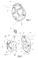
- Figure 1 an ancillary 1 of installation a glenoid implant, adapted to guide directionally the drill of a drill for medical use not shown.
- a glenoid implant When placing a glenoid implant on a patient's shoulder blade to form a prosthesis shoulder, the surgeon must dig into the glenoid the scapula a receiving channel for a keel the glenoid implant.
- the management that this channel is to be formed is different.
- Optimal here means “preferential” considering all the medical parameters brought to the attention of the surgeon, the latter for example has a series of scanned sections of the scapula on which it is intended to place the implant and determine this direction preferred.
- the exact location of the point of application of the piercing member is secondary to the preferred direction, it being understood that this point of application is located in a central area of the cavity glenoid.
- Figure 2 shows a dotted line shoulder blade 2 of a patient as it appears at surgeon using a CT scan.
- the C-C axis indicates the preferred direction chosen by the surgeon as the direction in which the piercing member should to be applied.
- the ancillary 1 essentially comprises a plate 4 on which are reported means 6 adjusting the direction of a drilling guide by compared to the stage.
- the plate 4 is formed of a metal body 10 having, in a direction denoted Z-Z a dimension smaller than on the two orthogonal directions remaining, indicated by axes X-X and Y-Y. Subsequently, the lower and upper terms will be oriented by relation to the X-X axis so that for example next to Figure 3, the upper term corresponds to the part high of this figure, while the lower term corresponds to the lower part.
- the body 10 of the plate 4 defines a surface convex 12 intended to come into surface support against scapula 2, as shown in figure 2.
- the surface 12 is provided with pins projections 16 intended to facilitate the retention of the plate relative to the scapula as will be explained later.
- the body 10 delimits a surface 18 opposite the surface 12, substantially planar and from which are provided, at the four corners of the body 10, surfaces bevelled 20.
- surfaces 20 are formed threaded recesses 21, adapted to receive means (not shown) removable fixing for a handle manipulation of the plate known per se.
- the body 10 internally defines an opening through 22, central axis Z-Z and cross-shaped in cross section.
- the opening 22 has two pairs of diametrically opposite lobes, the lobes of the same pair being aligned respectively according to the directions X-X and Y-Y.
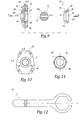
- the adjustment means 6 are formed by a barrel 30 shown in more detail in Figures 3 to 5.
- This cannon comprises a tubular body 32 of axis Z-Z and of profile exterior substantially complementary to the profile of the through opening 22 of the body 10.
- the body 32 is closed at one end by a bottom overall hemispherical 34 which forms, with the outer surface of the body 32, a planar shoulder 35 radially projecting from relative to the Z-Z axis.
- holes straight through 36 whose respective axes are substantially concurrent at a point denoted P belonging to the Z-Z axis.
- These holes 36 are distributed in a first 38 series of holes that extend in the foreground containing the axes X-X and Z-Z and corresponding substantially in the section plane of FIG. 4, and a second series 40 of holes which extend in a second plane containing the axes Y-Y and Z-Z and corresponding to the section plane of the figure 5.
- each series 38, 40 of holes 36 the spacing angular between two adjacent holes on the same side of the Z-Z axis is approximately 10 °.
- Angular spacing between the Z-Z axis and one of the two holes 36 in the 38 series located most in the center of the cover 34 is approximately 5 °, while the same angular deviation for the two holes more in the center of series 40 is about 10 °
- a screw 42 is housed in an additional hole extending along the X-X direction and leading on one side to the edge of the body 10 and on the other side in the opening 22.
- This screw makes it possible to retain along the axis Z-Z the barrel 30 in opening 22.
- the surgeon When the surgeon has determined, for example at means of CT scans of a patient's shoulder, the privileged direction C-C in which he wishes anchor the glenoid implant in the scapula and therefore apply a drill bit, it supports the ancillary 1 against the scapula. More specifically, the surface 12 of the platinum 4 is pressed against the bony glenoid of the scapula 2, as shown in FIG. 2.
- ancillary 1 is advantageously handled by a handle connected to the plate 10 at the beveled surfaces 20.
- the pins 16 facilitate the fixing of the plate by compared to the scapula.
- the surgeon While the barrel 30 is received and immobilized in the opening 22 of the plate, the surgeon selects, among the set of holes 36 in the barrel, the only hole of which the longitudinal axis is closest to the direction preferential C-C he chose. If necessary, the surgeon disengages the barrel 30 from the stage, the fact turn it a quarter turn then put it back in the cruciform opening 22, which allows to have adjustable drilling directions with a step of 5 ° in the two planes containing respectively the axes X-X and Z-Z and the Y-Y and Z-Z axes.
- the chosen direction C-C forms, in a plane containing the axes Y-Y and Z-Z, an angular deviation about 15 ° from the central axis of the cavity glenoid, so the surgeon will use a only holes from the 38 series of the barrel.
- the drill of a drill in order to drill or at least one initiation of drilling in the direction imposed by the hole.
- the surgeon can widen the hole drilled in the scapula by a larger diameter drill or other shaping. It can also use a pin milling which, wedged in the drilled hole, allows to spare a glenoid resection plane orthogonal to the direction CC.
- Ancillary 1 is thus easy to use and puts quickly available to the surgeon a guide application of an organ, in particular a drilling guide, whose direction is adjusted according to the direction preferential that the surgeon chose.
- Figures 6 and 7 is shown a variant of the ancillary 1 which differs from the ancillary of the figures previous by the number and the arrangement of the holes of guide 36 provided by the barrel 30.
- series of holes 42, 44, 46 and 48 are located respectively in the four bounded quadrants by the series of holes 38 and 40, forming a grid from the bottom 34 of the barrel. This variant makes available to the surgeon more guidance directions than ancillary Figures 1 to 5.
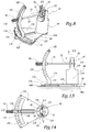
- FIGS 8 to 14 show a second instrument 50 according to the invention.
- This ancillary is intended to be used in the same context as the ancillary 1 of the previous figures, that is to say to guide the rod an organ, in particular the drill of a drill for use medical, when placing a glenoid implant of a shoulder prosthesis.
- this ancillary 50 comprises a plate 52 formed of a body metallic 54 of substantially the same shape as the body 10 of plate 4 and oriented with respect to axes X-X, Y-Y and Z-Z defined in the same way as in Figure 3.
- the body 54 defines a convex surface 56 intended to come to rest against a patient's bone glenoid, advantageously provided with mooring pins 58 substantially similar to the pins 16 of the plate 10, as well as a planar opposite surface 59.
- the body 54 is also suitable to be removably attached to a manipulation handle not shown.
- a through opening 60 of axis of revolution Z-Z In the body 54 of the plate 52 is formed a through opening 60 of axis of revolution Z-Z. As shown in FIG. 9, this opening comprises, successively from the face 56 of the body 54, a part frustoconical 62 which diverges towards the face 56, part 64 in trunk of sphere of center O and a cylindrical part 66 threaded.
- the ancillary 50 also includes means 70 adjusting the direction of a drilling guide by relative to the plate 52, comprising on the one hand, a sphere 72 drilled right through one of its diameters in forming a single cylindrical bore 74 of axis Z'-Z ', and on the other hand, a nut 76.
- the sphere 72 has an outer surface 72 a substantially complementary to the hemispherical part 64 of the opening 60.
- the nut 76 is formed of a tubular body 78, of axis ZZ and threaded in a manner substantially complementary to the tapped cylindrical part 66 of the opening 60, and of a hexagonal head 80 which forms with the tubular body 78 a shoulder 82 radially projecting with respect to the axis of the body 78.
- the nut 76 internally provides a bore 84 formed, on the side of the tubular body 78, of a part 81 substantially in the form of a trunk of a sphere complementary to the external surface of the sphere 72, and, on the side of the head 80, of a flared part 83.
- the sphere 72 By cooperation of the outer surface 72 a of the sphere 72 with the surface 64 of the opening 60, the sphere 72 is movable relative to the platen 52 in the manner of a ball joint center O.
- the nut is able to immobilize the sphere 72 relative to the plate.
- the flat face 59 of the plate forms a stop surface for the shoulder 82, thus avoiding excessive tightening, or even deterioration of the sphere by the tight nut.
- ancillary 50 comprises advantageously a key 86, shown in FIG. 12, provided with a hollow head drive head hexagonal nut.
- the sphere 72 being movable relative to the plate 52 when nut 76 is not tightened, this sphere is adapted to be moved so that the axis Z'-Z 'of its bore 74 is adjusted according to the direction privileged C-C chosen beforehand by the surgeon.
- the ancillary 50 further comprises means 88 for displacement and positioning of the sphere 72 by relative to plate 52, shown in FIGS. 8, 13 and 14.
- These means comprise a rigid support 90 of a part and a rod 92 for driving the sphere 72 on the other hand, connected to support 88.
- the rod 92 is adapted to one of its ends, to be threaded inside the hole 74 of the sphere 72, and has at its other end a knurled handle 94 for handling the rod, added from removably on this rod like a nut.
- Bar 114 is pivotally mounted relative to the rest of the support 90, around a pivot axis 118 perpendicular to the surface 98 and formed for example by a cylindrical pin guided in rotation in a recess correspondent formed in the horizontal protractor plate 106 and the base 100.
- Each arm 116 has a profile along its length essentially semicircular with center O and bears corresponding angle graduations, referenced 120 on Figures 8 and 13.
- the zero scale corresponds to the position of the rod 92 perpendicular to the plane Q.
- the arms 116 are received in a groove 122 of the protractor horizontal 106, semicircular centered on the axis of pivoting 118.
- the periphery of the groove 122 carries angular graduations referenced 124.
- the zero graduation corresponds to the position of the rod 92 perpendicular to the plane Q.
- the arms 116 are connected by a jumper 126.
- the surgeon determines the preferred direction C-C that he wants to dig the canal receiving a keel from the glenoid implant.
- the entire vertical protractor 112 pivots around the axis 118 and the angular orientation of the rod in a plane perpendicular to the X-X axis of the stage is set.
- the surgeon ensures the correct positioning rod angle by direct reading on the references corresponding angles 120 and 124.
- the surgeon uses the key 86 to tighten firmly the nut 76 and thus immobilize the sphere 72 by relative to the plate 52.
- the head of the key 86 is at this effect with a slot wide enough to allow to engage the key on the head 80 of the nut without be bothered by the rod 92.
- the second embodiment of the ancillary 50 has the advantage, compared to the ancillary 1 of Figures 1 to 5, to allow the surgeon to adjust continuously the direction of the drilling guide following all anatomically conceivable directions, and not only following a discrete series of these directions.
- the bearing face 12 or 56 is flat.
- the positions of points P and O above may deviate somewhat from those described upper.
- the adjustment means 70 are replaced by a sliding system allowing directional adjustment in a single plane.
- the ancillary device according to the invention is able to directionally guide any piercing member, shaping or the like other than a drilling forest, for example example an impact pin or a marking nail.
Abstract
Description
La présente invention concerne un ancillaire de pose d'un implant glénoïdien.The present invention relates to a fitting aid of a glenoid implant.
Lors de l'implantation d'une prothèse d'épaule, il est parfois nécessaire de poser à l'extrémité articulaire de l'omoplate d'un patient, un implant glénoïdien qui, d'un côté, s'ancre rigidement dans l'omoplate et qui, de l'autre côté, délimite une surface articulaire de coopération avec la tête d'un implant huméral fixé à l'extrémité correspondante de l'humérus du patient. Pour ancrer fermement l'implant glénoïdien dans l'omoplate, cet implant comporte généralement une quille en saillie du reste de l'implant et destinée à être reçue et immobilisée dans un canal creusé à l'intérieur de l'omoplate à l'aide d'un organe approprié, notamment le forêt d'une perceuse à usage médical. Lors de l'application de cet organe sur l'omoplate, il est courant d'utiliser un ancillaire de guidage qui limite les risques de dérapage de la tige ou de la pointe de cet organe.When implanting a shoulder prosthesis, it is sometimes necessary to lay at the joint end of a patient's scapula, a glenoid implant that, from a side, rigidly anchored in the scapula and which, on the other side, delimits a joint surface for cooperation with the head of a humeral implant attached to the end corresponding to the patient's humerus. To anchor the glenoid implant firmly in the scapula, this implant usually has a protruding keel from the rest of the implant and intended to be received and immobilized in a canal dug inside the scapula using a suitable body, in particular the forest of a drill for use medical. When applying this organ on the scapula, it is common to use an ancillary of guidance which limits the risks of the rod slipping or the tip of this organ.
Le document US-B1-6,379,386 décrit de tels ancillaires de guidage. En particulier, en regard de ses figures 5 à 9, ce document décrit un ancillaire de guidage pour le foret d'une perceuse, comportant une platine destinée à venir en appui surfacique contre la glène de l'omoplate d'un patient et à l'intérieur de laquelle est formé un trou central de guidage du foret de perçage. Grâce à cet ancillaire, le chirurgien est à même de creuser une amorce d'un canal. Ce document décrit également, en regard de ses figures 15 à 17, un autre ancillaire comportant une platine d'appui sur l'omoplate, à l'intérieur de laquelle sont formés trois trous de guidages successifs d'un foret de perçage. La face de la platine tournée vers l'omoplate est pourvue d'une saillie adaptée pour venir se loger dans l'amorce préalablement creusée. Par applications successives de la perceuse au niveau de chacun des trois trous, le chirurgien dégage un volume de matière osseuse important et creuse ainsi un canal de réception suffisamment grand pour la quille de l'implant glénoïdien envisagé dans ce document.Document US-B1-6,379,386 describes such ancillaries guide. In particular, with reference to Figures 5 to 9, this document describes a guide tool for the drill a drill, comprising a plate intended to come in surface support against the glenoid of the scapula of a patient and inside which is formed a central hole of guiding the drill bit. Thanks to this ancillary, the surgeon is able to dig a primer from a canal. This document also describes, with reference to its figures 15 to 17, another ancillary device comprising a support plate on the scapula, inside which three are formed successive guide holes of a drill bit. The face of the plate facing towards the scapula is provided with a projection adapted to be housed in the primer previously dug. By successive applications of the drill at each of the three holes, the surgeon releases a large volume of hollow bone material thus a reception channel large enough for the keel of the glenoid implant envisaged in this document.
Selon la morphologie du patient, l'état de l'omoplate sur laquelle un implant glénoïdien est destiné à être posé, les conditions opératoires et/ou la forme exacte de l'implant à poser, la direction longitudinale du canal de réception de la quille de l'implant est différente. Le chirurgien a généralement intérêt à creuser un canal dans la direction où l'omoplate du patient est la plus résistante, notamment dans une zone épaisse où l'os est abondant et sain.Depending on the patient's morphology, the condition of the scapula on which a glenoid implant is intended to be placed, the operating conditions and / or the exact form of the implant to be placed, the longitudinal direction of the reception of the implant keel is different. The surgeon usually has an interest in digging a canal in the direction where the patient's shoulder blade is most resistant, especially in a thick area where the bone is abundant and healthy.
Actuellement, la direction pour creuser ce canal est repérée sur l'omoplate soit de façon empirique par le chirurgien, soit, lorsque ce dernier utilise un ancillaire tel que celui décrit dans le document US-6,379,386 mentionné ci-dessus, arbitrairement imposée par la platine de l'ancillaire utilisé. Si le chirurgien tente d'appliquer l'organe de perçage suivant une direction choisie sans utiliser d'ancillaire de guidage, il court le risque de voir l'organe de perçage déraper et/ou creuser un canal dans une direction différente de celle qu'il visait, moins favorable pour la pose et la tenue ultérieure de l'implant glénoïdien.Currently, the direction to dig this channel is spotted on the scapula either empirically by the surgeon, that is, when the latter uses an ancillary such as that described in document US-6,379,386 mentioned above, arbitrarily imposed by the turntable of the ancillary used. If the surgeon tries to apply the piercing member in a chosen direction without use a guide, it runs the risk of see the piercing member slip and / or dig a channel in a different direction from the one he was aiming for, minus favorable for placement and subsequent holding of the implant glenoid.
Le but de la présente invention est de proposer un ancillaire de structure simple et qui permette d'imposer à l'organe de perçage, de façonnage ou analogue utilisé lors de la pose d'un implant glénoïdien, par exemple au foret d'une perceuse à usage médical, une direction d'application choisie par le chirurgien, le cas échéant en préopératoire, sur toute une gamme de directions envisageables, voire pour n'importe quelle direction anatomiquement envisageable. The purpose of the present invention is to provide a ancillary of simple structure and which allows to impose on the piercing, shaping or similar member used during the placement of a glenoid implant, for example in the drill a drill for medical use, an application direction chosen by the surgeon, if necessary preoperatively, across a range of directions possible, even for any direction anatomically possible.
A cet effet, l'invention a pour objet un ancillaire de pose d'un implant glénoïdien, du type comportant une platine qui délimite une surface d'appui destinée à venir s'appuyer contre la glène d'une omoplate d'un patient et qui forme un guide directionnel pour un organe de perçage, de façonnage ou analogue, caractérisé en ce qu'il comporte des moyens d'ajustement de la direction du guide par rapport à la platine.To this end, the invention relates to an ancillary of placement of a glenoid implant, of the type comprising a plate which delimits a bearing surface intended to come lean against the glenoid of a patient's shoulder blade and which forms a directional guide for a piercing member, shaping or the like, characterized in that it comprises means for adjusting the direction of the guide by compared to the stage.
Par sollicitation de ces moyens d'ajustement, le chirurgien est à même de disposer d'un guidage ajusté suivant la direction qu'il aura préalablement choisie, par exemple suite à l'analyse de coupes scanner de l'omoplate réalisées avant l'intervention chirurgicale. Lorsque ces moyens d'ajustement sont adaptés pour être reliés de façon amovible à la platine, le chirurgien peut juste avant l'opération, ou si nécessaire en per-opératoire, ajuster la direction de guidage imposée à l'organe de perçage utilisé.By requesting these means of adjustment, the surgeon is able to have an adjusted guide depending on the direction he has previously chosen, by example following the analysis of scanned sections of the scapula performed before surgery. When these adjustment means are adapted to be connected so removable to the plate, the surgeon can just before the operation, or if necessary intraoperatively, adjust the guide direction imposed on the piercing member used.
Suivant d'autres caractéristiques de cet ancillaire, prises isolément ou selon toutes les combinaisons techniquement possibles :
- les moyens d'ajustement de la direction du guide sont adaptés pour être reçus et immobilisés dans une ouverture traversante formée dans la platine et débouchant sur la surface d'appui de la platine ;
- les moyens d'ajustement permettent d'ajuster la direction du guide par rapport à la platine au moins dans deux plans sensiblement perpendiculaires l'un à l'autre ;
- les moyens d'ajustement de la direction du guide comportent un canon pourvu de plusieurs trous traversants rectilignes, l'un desdits trous formant le guide directionnel pour l'organe de perçage, de façonnage ou analogue ;
- le canon comporte un corps tubulaire fermé à une de ses extrémités par un fond, les trous traversants étant formés dans le fond et débouchant à l'intérieur du corps tubulaire, lequel corps tubulaire présente en coupe transversale un profil extérieur adapté pour coopérer avec une ouverture traversante de la platine de façon à immobiliser le canon dans cette ouverture ;
- les axes des trous sont sensiblement concourants en un point situé sensiblement dans le prolongement géométrique de la face convexe de la platine ;
- une première série de trous du canon est alignée selon un premier plan et une seconde série d'autres trous du canon est alignée suivant un second plan sensiblement orthogonal au premier plan ;
- dans chacune des première et seconde séries de trous, les axes des trous situés d'un même côté de l'axe central du canon sont décalés angulairement les uns par rapport aux autres d'une valeur sensiblement constante ;
- d'autres séries de trous sont prévus dans les quadrants définis par les première et seconde séries de trous ;
- les moyens d'ajustement de la direction du guide comportent d'une part, un élément mobile par rapport à la platine et d'autre part, un élément d'immobilisation de l'élément mobile par rapport à la platine, l'élément mobile étant pourvu d'un perçage traversant rectiligne adapté pour former le guide directionnel pour l'organe de perçage, de façonnage ou analogue ;
- la direction du perçage de l'élément mobile est continûment ajustable ;
- l'élément mobile présente une surface adaptée pour coopérer avec une surface associée de la platine ;
- la surface de l'élément mobile adaptée pour coopérer avec la surface associée de la platine est sensiblement sphérique ;
- il comporte en outre un outil de commande de l'élément d'immobilisation ;
- il comprend en outre des moyens de déplacement et de positionnement de l'élément mobile par rapport à la platine adaptés pour amener le perçage de l'élément mobile sensiblement suivant une direction choisie ;
- les moyens de déplacement et de positionnement de l'élément mobile comportent un support rigide de retenue pour la platine et une tige d'entraínement de l'élément mobile, déplaçable par rapport au support rigide, ledit support étant pourvu de deux rapporteurs adaptés pour rapporter la position angulaire de la tige dans deux plans sensiblement perpendiculaires l'un à l'autre.
- the means for adjusting the direction of the guide are adapted to be received and immobilized in a through opening formed in the plate and opening onto the bearing surface of the plate;
- the adjustment means make it possible to adjust the direction of the guide relative to the plate at least in two planes substantially perpendicular to each other;
- the means for adjusting the direction of the guide comprise a barrel provided with several rectilinear through holes, one of said holes forming the directional guide for the drilling, shaping or similar member;
- the barrel has a tubular body closed at one of its ends by a bottom, the through holes being formed in the bottom and opening out inside the tubular body, which tubular body has in cross section an external profile adapted to cooperate with an opening through the plate so as to immobilize the barrel in this opening;
- the axes of the holes are substantially concurrent at a point located substantially in the geometric extension of the convex face of the plate;
- a first series of barrel holes is aligned in a first plane and a second series of other barrel holes is aligned in a second plane substantially orthogonal to the foreground;
- in each of the first and second series of holes, the axes of the holes located on the same side of the central axis of the barrel are angularly offset from one another by a substantially constant value;
- other series of holes are provided in the quadrants defined by the first and second series of holes;
- the means for adjusting the direction of the guide comprise on the one hand, an element movable relative to the plate and on the other hand, an element for immobilizing the movable element relative to the plate, the movable element being provided with a straight through hole adapted to form the directional guide for the piercing, shaping or similar member;
- the direction of drilling of the movable element is continuously adjustable;
- the movable element has a surface adapted to cooperate with an associated surface of the plate;
- the surface of the mobile element adapted to cooperate with the associated surface of the plate is substantially spherical;
- it further comprises a tool for controlling the immobilizing element;
- it further comprises means for moving and positioning the movable element relative to the plate adapted to bring the piercing of the movable element substantially in a chosen direction;
- the means of displacement and positioning of the movable element comprise a rigid retaining support for the plate and a rod for driving the movable element, movable relative to the rigid support, said support being provided with two reporters adapted to bring back the angular position of the rod in two planes substantially perpendicular to each other.
L'invention a également pour objet une méthode de pose d'un implant glénoïdien, dans laquelle :
- on dispose d'au moins une coupe scanner ou analogue de l'omoplate d'un patient,
- on détermine une direction préférentielle d'application sur l'omoplate d'un organe de perçage, de façonnage ou analogue,
- on utilise un ancillaire de guidage qui comporte une platine formant un guide directionnel pour ledit organe de perçage et des moyens d'ajustement de la direction du guide par rapport à la platine,
- on plaque une surface de la platine sur la glène de l'omoplate,
- on introduit l'organe de perçage dans le guide dont la direction est ajustée suivant la direction préférentielle, et
- on actionne l'organe de perçage de façon à agir sur l'omoplate suivant la direction préférentielle.
- there is at least one CT or similar section of the scapula of a patient,
- a preferred direction of application is determined on the scapula of a piercing, shaping or similar member,
- a guide device is used which includes a plate forming a directional guide for said piercing member and means for adjusting the direction of the guide relative to the plate,
- one places a surface of the plate on the glenoid of the scapula,
- the piercing member is introduced into the guide, the direction of which is adjusted in the preferred direction, and
- the piercing member is actuated so as to act on the scapula in the preferred direction.
Suivant deux variantes de cette méthode :
- les moyens d'ajustement de l'ancillaire de guidage comportent un canon pourvu de plusieurs trous traversants rectilignes, et dans laquelle, après avoir plaqué la platine sur la glène de l'omoplate, on introduit l'organe de perçage dans le trou qui, parmi les trous traversants du canon, s'étend suivant une direction proche ou la direction la plus proche de la direction préférentielle ; ou
- les moyens d'ajustement de l'ancillaire de guidage comportent un élément mobile par rapport à la platine et un élément d'immobilisation de l'élément mobile par rapport à la platine, ledit élément mobile étant pourvu d'un perçage traversant rectiligne, et dans laquelle, avant d'avoir plaqué la platine sur la glène de l'omoplate, on positionne l'élément mobile par rapport à la platine de façon à amener le perçage de l'élément mobile sensiblement suivant la direction préférentielle puis on immobilise l'élément mobile par rapport à la platine par l'intermédiaire de l'élément d'immobilisation.
- the means for adjusting the ancillary guide comprise a barrel provided with several rectilinear through holes, and in which, after having pressed the plate onto the glenoid of the scapula, the piercing member is introduced into the hole which, among the through holes of the barrel, extends in a direction close to or the direction closest to the preferred direction; or
- the means for adjusting the guiding ancillary device comprise a movable element relative to the plate and an element for immobilizing the movable element relative to the plate, said movable element being provided with a straight through hole, and in which, before having pressed the plate on the glenoid of the scapula, the mobile element is positioned relative to the plate so as to bring the piercing of the mobile element substantially in the preferred direction and then immobilizes the element movable relative to the plate via the immobilizing element.
L'invention sera mieux comprise à la lecture de la description qui va suivre, donnée uniquement à titre d'exemple et faite en se référant aux dessins sur lesquels :
- la figure 1 est une vue en perspective d'un premier mode de réalisation d'un ancillaire selon l'invention ;
- la figure 2 est une vue en élévation, prise selon la flèche II indiquée sur la figure 1, de l'ancillaire appliqué sur une omoplate d'un être humain ;
- la figure 3 est une vue en perspective en éclaté de l'ancillaire de la figure 1 ;
- les figures 4
et 5 sont des coupes selon les plans indiqués IV et V sur la figure 3 ; - la figure 6 est une vue analogue à la figure 3 d'une variante de l'ancillaire de la figure 1 ;
- la figure 7 est une vue en élévation prise selon la flèche VII indiquée sur la figure 6 ;
- la figure 8 est une vue en perspective d'un second mode de réalisation d'un ancillaire selon l'invention ;
- la figure 9 est une vue en coupe longitudinale de certains éléments de l'ancillaire de la figure 8, représentés à plus grande échelle ;
- la figure 10 est une vue en élévation, prise selon la flèche X indiquée sur la figure 9, de l'éléments sur lequel pointe cette flèche X ;
- la figure 11 est une vue en élévation, prise selon la flèche XI indiquée sur la figure 9, de l'élément sur lequel pointe cette flèche XI ;
- la figure 12 est une vue en élévation d'un outil utilisé lors de la manipulation de l'ancillaire de la figure 8 ;
- la figure 13 est une vue en élévation de côté de l'ancillaire de la figure 8 ; et
- la figure 14 est une vue de dessus de l'ancillaire de la figure 8.
- Figure 1 is a perspective view of a first embodiment of a device according to the invention;
- Figure 2 is an elevational view, taken along arrow II indicated in Figure 1, of the ancillary device applied to a shoulder blade of a human being;
- Figure 3 is an exploded perspective view of the ancillary of Figure 1;
- Figures 4 and 5 are sections along the planes indicated IV and V in Figure 3;
- Figure 6 is a view similar to Figure 3 of a variant of the instrument of Figure 1;
- Figure 7 is an elevational view taken along arrow VII indicated in Figure 6;
- Figure 8 is a perspective view of a second embodiment of an ancillary device according to the invention;
- Figure 9 is a longitudinal sectional view of some elements of the ancillary of Figure 8, shown on a larger scale;
- Figure 10 is an elevational view, taken along the arrow X indicated in Figure 9, of the elements to which this arrow X points;
- Figure 11 is an elevational view, taken along arrow XI indicated in Figure 9, of the element to which this arrow XI points;
- FIG. 12 is an elevation view of a tool used during the manipulation of the instrument of FIG. 8;
- Figure 13 is a side elevational view of the ancillary of Figure 8; and
- FIG. 14 is a top view of the ancillary device of FIG. 8.
Sur la figure 1 est représenté un ancillaire 1 de pose
d'un implant glénoïdien, adapté pour guider
directionnellement le foret d'une perceuse à usage médical
non représentée. Lors de la pose d'un implant glénoïdien
sur l'omoplate d'un patient, en vue de former une prothèse
d'épaule, le chirurgien doit creuser dans la glène de
l'omoplate un canal de réception pour une quille de
l'implant glénoïdien. En fonction de la morphologie du
patient, de la géométrie de cette quille, de la pathologie
ayant motivée la pose de l'implant, etc., la direction
suivant laquelle ce canal est à former est différente. Pour
déterminer la direction optimale de ce canal, le terme
« optimal » signifiant ici « préférentiel » en considérant
l'ensemble des paramètres médicaux portés à la connaissance
du chirurgien, ce dernier dispose par exemple d'une série
de coupes scanner de l'omoplate sur laquelle il est prévu
de poser l'implant et détermine cette direction
privilégiée. La localisation exacte du point d'application
de l'organe de perçage est secondaire par rapport à la
direction privilégiée, étant entendu que ce point
d'application se situe dans une zone centrale de la cavité
glénoïdienne. La figure 2 représente en pointillé une
omoplate 2 d'un patient telle qu'elle apparaít au
chirurgien par une coupe scanner. L'axe C-C indique la
direction privilégiée choisie par le chirurgien comme étant
la direction suivant laquelle l'organe de perçage devrait
être appliqué.In Figure 1 is shown an ancillary 1 of installation
a glenoid implant, adapted to guide
directionally the drill of a drill for medical use
not shown. When placing a glenoid implant
on a patient's shoulder blade to form a prosthesis
shoulder, the surgeon must dig into the glenoid
the scapula a receiving channel for a keel
the glenoid implant. Depending on the morphology of the
patient, the geometry of this keel, the pathology
having motivated the implant placement, etc., the management
that this channel is to be formed is different. For
determine the optimal direction of this channel, the term
"Optimal" here means "preferential" considering
all the medical parameters brought to the attention
of the surgeon, the latter for example has a series
of scanned sections of the scapula on which it is intended
to place the implant and determine this direction
preferred. The exact location of the point of application
of the piercing member is secondary to the
preferred direction, it being understood that this point
of application is located in a central area of the cavity
glenoid. Figure 2 shows a dotted
A cet effet, l'ancillaire 1 comporte essentiellement
une platine 4 sur laquelle sont rapportés des moyens 6
d'ajustement de la direction d'un guide de perçage par
rapport à la platine.To this end, the ancillary 1 essentially comprises
a
Plus précisément, comme représenté sur les figures 1 à
5, la platine 4 est formée d'un corps métallique 10
présentant, suivant une direction notée Z-Z une dimension
plus petite que sur les deux directions orthogonales
restantes, indiquées par des axes X-X et Y-Y. Par la suite,
les termes inférieur et supérieur seront orientés par
rapport à l'axe X-X de sorte que, par exemple en regard de
la figure 3, le terme supérieur correspond à la partie
haute de cette figure, tandis que le terme inférieur
correspond à la partie basse.More specifically, as shown in Figures 1 to
5, the
Le corps 10 de la platine 4 délimite une surface
convexe 12 destinée à venir en appui surfacique contre
l'omoplate 2, comme représenté sur la figure 2.
Avantageusement, la surface 12 est pourvue de picots
saillants 16 destinés à faciliter la retenue de la platine
par rapport à l'omoplate comme il sera expliqué plus loin. The
Le corps 10 délimite une surface 18 opposée à la
surface 12, sensiblement plane et à partir de laquelle sont
ménagées, aux quatre coins du corps 10, des surfaces
biseautées 20. Dans ces surfaces 20 sont formés des
évidements taraudés 21, adaptés pour recevoir des moyens
(non représentés) de fixation amovible pour un manche de
manipulation de la platine connu en soi.The
Le corps 10 délimite intérieurement une ouverture
traversante 22, d'axe central Z-Z et de profil cruciforme
en coupe transversale. Plus précisément, l'ouverture 22
comporte deux paires de lobes diamétralement opposés, les
lobes d'une même paire étant alignés respectivement suivant
les directions X-X et Y-Y.The
Les moyens d'ajustement 6 sont formés par un canon 30
représenté plus en détail sur les figures 3 à 5. Ce canon
comporte un corps tubulaire 32 d'axe Z-Z et de profil
extérieur sensiblement complémentaire du profil de
l'ouverture traversante 22 du corps 10. Le corps 32 est
fermé à une de ses extrémités par un fond globalement
hémisphérique 34 qui forme, avec la surface extérieure du
corps 32, un épaulement plan 35 radialement saillant par
rapport à l'axe Z-Z.The adjustment means 6 are formed by a
A l'intérieur de ce fond 34 sont formés des trous
traversants rectilignes 36 dont les axes respectifs sont
sensiblement concourants en un point noté P appartenant à
l'axe Z-Z. Ces trous 36 se répartissent en une première
série 38 de trous qui s'étendent dans un premier plan
contenant les axes X-X et Z-Z et correspondant sensiblement
au plan de coupe de la figure 4, et une seconde série 40 de
trous qui s'étendent dans un second plan contenant les axes
Y-Y et Z-Z et correspondant au plan de coupe de la figure
5.Inside this bottom 34 are formed holes
straight through 36 whose respective axes are
substantially concurrent at a point denoted P belonging to
the Z-Z axis. These
Dans chaque série 38, 40 de trous 36, l'écartement
angulaire entre deux trous adjacents situés d'un même côté
de l'axe Z-Z vaut sensiblement 10°. L'écartement angulaire
entre l'axe Z-Z et l'un des deux trous 36 de la série 38
situés le plus au centre du couvercle 34 vaut environ 5°,
tandis que le même écart angulaire pour les deux trous les
plus au centre de la série 40 vaut environ 10°In each
Par coopération du corps tubulaire 32 avec l'ouverture
traversante 22 de la platine 10, le canon 30 est à même
d'être reçu et immobilisé par rapport à la platine 4,
l'épaulement 35 se positionnant alors en butée contre la
surface sensiblement plane 18 de la platine, comme
représenté sur la figure 2. Le point P est alors inscrit
sensiblement dans le prolongement géométrique de la face 12
destinée à venir en appui contre l'omoplate 2.By cooperation of the
Dans la partie supérieure de la platine 4, une vis 42
est logée dans un perçage complémentaire s'étendant suivant
la direction X-X et débouchant d'un côté sur le chant du
corps 10 et de l'autre côté dans l'ouverture 22.In the upper part of the
Cette vis permet de retenir suivant l'axe Z-Z le canon
30 dans l'ouverture 22.This screw makes it possible to retain along the axis Z-Z the
L'utilisation de l'ancillaire 1 lors de la pose d'un implant glénoïdien pour prothèse d'épaule est la suivante :The use of ancillary 1 when installing a Glenoid implant for shoulder prosthesis is as follows:
Lorsque le chirurgien a déterminé, par exemple au
moyen de coupes scanner de l'épaule d'un patient, la
direction privilégiée C-C suivant laquelle il souhaite
ancrer l'implant glénoïdien dans l'omoplate et donc
appliquer un foret de perçage, il met en appui l'ancillaire
1 contre l'omoplate. Plus précisément, la surface 12 de la
platine 4 est plaquée contre la glène osseuse de l'omoplate
2, comme représentée sur la figure 2. A cet effet,
l'ancillaire 1 est avantageusement manipulé par un manche
relié à la platine 10 au niveau des surfaces biseautées 20.
Les picots 16 facilitent l'amarrage de la platine par
rapport à l'omoplate. When the surgeon has determined, for example at
means of CT scans of a patient's shoulder, the
privileged direction C-C in which he wishes
anchor the glenoid implant in the scapula and therefore
apply a drill bit, it supports the ancillary
1 against the scapula. More specifically, the
Alors que le canon 30 est reçu et immobilisé dans
l'ouverture 22 de la platine, le chirurgien sélectionne,
parmi l'ensemble des trous 36 du canon, l'unique trou dont
l'axe longitudinal est le plus proche de la direction
préférentielle C-C qu'il a choisie. Si nécessaire, le
chirurgien dégage le canon 30 de la platine, le fait
pivoter d'un quart de tour puis le remet en place dans
l'ouverture cruciforme 22, ce qui permet de disposer de
directions de perçage ajustables avec un pas de 5° dans les
deux plans contenant respectivement les axes X-X et Z-Z et
les axes Y-Y et Z-Z.While the
Sur la figure 2, la direction choisie C-C forme, dans un plan contenant les axes Y-Y et Z-Z, un écart angulaire d'environ 15° par rapport à l'axe central de la cavité glénoïdienne, de sorte que le chirurgien va utiliser un seul des trous de la série 38 du canon.In Figure 2, the chosen direction C-C forms, in a plane containing the axes Y-Y and Z-Z, an angular deviation about 15 ° from the central axis of the cavity glenoid, so the surgeon will use a only holes from the 38 series of the barrel.
Il introduit ensuite dans ce trou le foret d'une perceuse, afin de réaliser un perçage ou au moins une amorce de perçage dans la direction imposée par le trou. Si nécessaire, après avoir dégagé l'ancillaire 1, le chirurgien peut élargir l'orifice percé dans l'omoplate par un foret de plus grand diamètre ou un autre organe de façonnage. Il peut également utiliser une broche de fraisage qui, calée dans l'orifice percé, permet de ménager un plan de résection glénoïdien orthogonal à la direction C-C.He then introduces into this hole the drill of a drill, in order to drill or at least one initiation of drilling in the direction imposed by the hole. Yes necessary, after having cleared the ancillary 1, the surgeon can widen the hole drilled in the scapula by a larger diameter drill or other shaping. It can also use a pin milling which, wedged in the drilled hole, allows to spare a glenoid resection plane orthogonal to the direction CC.
L'ancillaire 1 est ainsi d'utilisation facile et met rapidement à disposition du chirurgien un guide d'application d'un organe, notamment un guide de perçage, dont la direction est ajustée suivant la direction préférentielle que le chirurgien a choisie.Ancillary 1 is thus easy to use and puts quickly available to the surgeon a guide application of an organ, in particular a drilling guide, whose direction is adjusted according to the direction preferential that the surgeon chose.
Sur les figures 6 et 7 est représentée une variante de
l'ancillaire 1 qui se distingue de l'ancillaire des figures
précédentes par le nombre et la disposition des trous de
guidage 36 ménagés par le canon 30. En plus des séries de
trous 38 et 40, des séries de trous 42, 44, 46 et 48 sont
situés respectivement dans les quatre quadrants délimités
par les séries de trous 38 et 40, en formant un quadrillage
du fond 34 du canon. Cette variante met à la disposition du
chirurgien plus de directions de guidage que l'ancillaire
des figures 1 à 5.In Figures 6 and 7 is shown a variant of
the ancillary 1 which differs from the ancillary of the figures
previous by the number and the arrangement of the holes of
Sur les figures 8 à 14 est représenté un second
ancillaire 50 conforme à l'invention. Cet ancillaire est
destiné à être utilisé dans le même cadre que l'ancillaire
1 des figures précédentes, c'est-à-dire pour guider la tige
d'un organe, notamment le foret d'une perceuse à usage
médical, lors de la pose d'un implant glénoïdien d'une
prothèse d'épaule.Figures 8 to 14 show a
Comme représenté en détail sur les figures 8 à 11, cet
ancillaire 50 comporte une platine 52 formée d'un corps
métallique 54 de sensiblement même forme que le corps 10 de
la platine 4 et orienté par rapport à des axes X-X, Y-Y et
Z-Z définis de la même façon que sur la figure 3.As shown in detail in Figures 8 to 11, this
ancillary 50 comprises a
Le corps 54 délimite une surface convexe 56 destinée à
venir s'appuyer contre la glène osseuse d'un patient,
avantageusement pourvue de picots d'amarrage 58
sensiblement analogues aux picots 16 de la platine 10,
ainsi qu'une surface opposée plane 59. Le corps 54 est
également adapté pour être fixé de manière amovible à un
manche de manipulation non représenté.The
Dans le corps 54 de la platine 52 est formée une
ouverture traversante 60 d'axe de révolution Z-Z. Comme
représenté sur la figure 9, cette ouverture comporte,
successivement depuis la face 56 du corps 54, une partie
tronconique 62 qui diverge vers la face 56, une partie 64
en tronc de sphère de centre O et une partie cylindrique 66
taraudée. In the
L'ancillaire 50 comporte également des moyens 70
d'ajustement de la direction d'un guide de perçage par
rapport à la platine 52, comprenant d'une part, une sphère
72 percée de part en part suivant un de ses diamètres en
formant un unique perçage cylindrique 74 d'axe Z'-Z', et
d'autre part, un écrou 76.The ancillary 50 also includes
Plus précisément, la sphère 72 présente une surface
extérieure 72a sensiblement complémentaire de la partie
hémisphérique 64 de l'ouverture 60. L'écrou 76 est formé
d'un corps tubulaire 78, d'axe Z-Z et fileté de façon
sensiblement complémentaire de la partie cylindrique
taraudée 66 de l'ouverture 60, et d'une tête hexagonale 80
qui forme avec le corps tubulaire 78 un épaulement 82
radialement saillant par rapport à l'axe du corps 78.
L'écrou 76 ménage intérieurement un alésage 84 formé, du
côté du corps tubulaire 78, d'une partie 81 sensiblement en
forme de tronc de sphère complémentaire de la surface
extérieure de la sphère 72, et, du côté de la tête 80,
d'une partie évasée 83.More specifically, the
Par coopération de la surface extérieure 72a de la
sphère 72 avec la surface 64 de l'ouverture 60, la sphère
72 est mobile par rapport à la platine 52 à la façon d'une
rotule de centre O. De plus, par engagement et coopération
des filetages du corps 78 de l'écrou 76 et de la partie
taraudée 66 de l'ouverture 60, l'écrou est à même
d'immobiliser la sphère 72 par rapport à la platine. La
face plane 59 de la platine forme une surface d'arrêt pour
l'épaulement 82, évitant ainsi un serrage excessif, voire
la détérioration de la sphère par l'écrou serré.By cooperation of the
Pour permettre d'appliquer un couple de serrage
important sur l'écrou 76, l'ancillaire 50 comporte
avantageusement une clef 86, représentée sur la figure 12,
pourvue d'une tête évidée d'entraínement de la tête
hexagonale de l'écrou. To allow the application of a tightening torque
important on
La sphère 72 étant mobile par rapport à la platine 52
lorsque l'écrou 76 n'est pas serré, cette sphère est
adaptée pour être déplacée de façon à ce que l'axe Z'-Z' de
son perçage 74 soit ajustée suivant la direction
privilégiée C-C choisie préalablement par le chirurgien.The
L'ancillaire 50 comporte en outre des moyens 88 de
déplacement et de positionnement de la sphère 72 par
rapport à la platine 52, représentés sur les figures 8, 13
et 14. Ces moyens comprennent un support rigide 90 d'une
part et une tige 92 d'entraínement de la sphère 72 d'autre
part, reliée au support 88.The ancillary 50 further comprises means 88 for
displacement and positioning of the
Plus précisément, la tige 92 est adaptée, à une de ses
extrémités, pour être enfilée à l'intérieur du perçage 74
de la sphère 72, et comporte à son autre extrémité une
poignée moletée 94 de manipulation de la tige, rapportée de
façon amovible sur cette tige à la façon d'un écrou.More specifically, the
Le support rigide 90 comporte quant à lui :
- une base d'appui sur une surface sensiblement
plane, référencée 98 uniquement sur la figure 13, formée
par exemple par une table ou tout plan de travail
analogue ; cette base est constituée par exemple d'un pied
96A et d'un
talon 96B ; une embase 100 de réception et d'immobilisation de la platine 52, pourvue d'un U dont les branches parallèles portent chacune une nervure longitudinale 102 adaptée pour être reçue dans une rainure correspondante 104 formée dans les chants latéraux du corps 54 de la platine, comme représenté sur la figure 14, de façon à positionner le plan Q de la platine, contenant le point O et les axes X-X et Y-Y, sensiblement perpendiculairement à lasurface plane 98 ;un rapporteur 106 dit horizontal, sous forme d'une plaque sensiblement parallèle à lasurface plane 98 ; ce rapporteur horizontal 106 est d'une part solidarisé à l'embase 100 et d'autre part relié fixement autalon 96B de la base d'appui par des pions defixation 110 ;un rapporteur 112 dit vertical, constitué d'unebarre plate 114 interposée entre letalon 96B et la plaque du rapporteur horizontal 106, et d'une paire debras 116 parallèles l'un à l'autre, qui s'étendent transversalement depuis labarre 114 et entre lesquels est retenue la tige 92.
- a support base on a substantially flat surface, referenced 98 only in FIG. 13, formed for example by a table or any similar work surface; this base consists for example of a
foot 96A and aheel 96B; - a
base 100 for receiving and immobilizing theplate 52, provided with a U whose parallel branches each carry alongitudinal rib 102 adapted to be received in acorresponding groove 104 formed in the lateral edges of thebody 54 of the plate, as shown in FIG. 14, so as to position the plane Q of the plate, containing the point O and the axes XX and YY, substantially perpendicular to theplanar surface 98; - a
protractor 106 said to be horizontal, in the form of a plate substantially parallel to theplanar surface 98; thishorizontal protractor 106 is on the one hand secured to thebase 100 and on the other hand fixedly connected to theheel 96B of the support base by fixingpins 110; - a
protractor 112 said vertical, consisting of aflat bar 114 interposed between theheel 96B and the plate of thehorizontal protractor 106, and a pair ofarms 116 parallel to each other, which extend transversely from thebar 114 and between which therod 92 is retained.
La barre 114 est montée pivotante par rapport au reste
du support 90, autour d'un axe de pivotement 118
perpendiculaire à la surface 98 et formé par exemple par un
pion cylindrique guidé en rotation dans un évidement
correspondant formé dans la plaque du rapporteur horizontal
106 et l'embase 100.
Chaque bras 116 présente suivant sa longueur un profil
essentiellement semi-circulaire de centre O et porte des
graduations d'angle correspondantes, référencées 120 sur
les figures 8 et 13. La graduation zéro correspond à la
position de la tige 92 perpendiculaire an plan Q. Au niveau
de leurs extrémités reliées à la plaque pivotante 114, les
bras 116 sont reçus dans une rainure 122 du rapporteur
horizontal 106, semi-circulaire centrée sur l'axe de
pivotement 118. La périphérie de la rainure 122 porte des
graduations angulaires référencées 124. La graduation zéro
correspond à la position de la tige 92 perpendiculaire au
plan Q. A leurs extrémités opposées, les bras 116 sont
reliés par un pontet de jonction 126.Each
L'utilisation de l'ancillaire 50 lors de la pose d'un implant glénoïdien pour une prothèse d'épaule est la suivante :The use of the ancillary 50 when installing a glenoid implant for a shoulder prosthesis is the next :
De la même façon que pour l'ancillaire 1 des figures 1 à 5, le chirurgien détermine la direction privilégiée C-C selon laquelle il souhaite procéder au creusement du canal de réception d'une quille de l'implant glénoïdien. In the same way as for the ancillary 1 of Figures 1 at 5, the surgeon determines the preferred direction C-C that he wants to dig the canal receiving a keel from the glenoid implant.
En partant de la configuration de l'ancillaire 50
représentée sur les figures 8, 13 et 14, dans laquelle la
platine 52 est immobilisé dans l'embase 100 du support 90,
le chirurgien, après avoir si nécessaire desserré
légèrement l'écrou 76, entraíne la sphère 72 au moyen de la
tige 92. Par déplacement de la poignée moletée 94 vers le
haut ou vers le bas par rapport à la surface plane 98,
l'inclinaison de la tige dans un plan perpendiculaire à
l'axe Y-Y est réglée. Par déplacement de la poignée 94 vers
la gauche ou vers la droite dans un plan parallèle à la
surface plane 98, l'ensemble du rapporteur vertical 112
pivote autour de l'axe 118 et l'orientation angulaire de la
tige dans un plan perpendiculaire à l'axe X-X de la platine
est réglée. Le chirurgien s'assure du bon positionnement
angulaire de la tige par lecture directe sur les références
angulaires correspondantes 120 et 124.Starting from the configuration of the ancillary 50
shown in Figures 8, 13 and 14, in which the
Une fois la tige 92 dirigée suivant la direction
choisie, le chirurgien utilise la clef 86 pour serrer
fermement l'écrou 76 et ainsi immobiliser la sphère 72 par
rapport à la platine 52. La tête de la clef 86 est à cet
effet pourvue d'une fente suffisamment large pour permettre
de mettre en prise la clef sur la tête 80 de l'écrou sans
être gêné par la tige 92.Once the
Il dégage ensuite la platine 52 de l'embase 100, en
retirant par exemple à la fois la platine, la sphère 72,
l'écrou serré 76 et la tige 92 en dévissant préalablement
la poignée 94. Puis la tige 92 est retirée sans difficulté
du trou 74.It then releases the
Ensuite, de la même façon que pour l'ancillaire 1 des
figures 1 à 5, le chirurgien place la platine 52 en appui
surfacique contre la glène osseuse du patient et introduit
à l'intérieur du trou 74 un foret de perçage.Then, in the same way as for ancillary 1 of
Figures 1 to 5, the surgeon places the
Le second mode de réalisation de l'ancillaire 50 présente l'avantage, par rapport à l'ancillaire 1 des figures 1 à 5, de permettre au chirurgien d'ajuster continûment la direction du guide de perçage suivant toutes les directions anatomiquement concevables, et pas seulement suivant une série discrète de ces directions.The second embodiment of the ancillary 50 has the advantage, compared to the ancillary 1 of Figures 1 to 5, to allow the surgeon to adjust continuously the direction of the drilling guide following all anatomically conceivable directions, and not only following a discrete series of these directions.
Divers aménagements et variantes aux deux modes de
réalisation de l'ancillaire décrits ci-dessus sont en outre
envisageables. A titre d'exemple, la face d'appui 12 ou 56
est plane. De plus, les positions des points P et O
précités peuvent s'écarter quelque peu de celles décrites
plus haut. A titre de variante, les moyens d'ajustement 70
à sphère sont remplacés par un système à glissière
permettant l'ajustement directionnel dans un plan unique.Various arrangements and variants to the two modes of
realization of the ancillary described above are further
conceivable. For example, the bearing
De même, l'ancillaire selon l'invention est à même de guider directionnellement tout organe de perçage, de façonnage ou analogue autre qu'un forêt de perçage, par exemple une broche à impacter ou un clou de marquage.Similarly, the ancillary device according to the invention is able to directionally guide any piercing member, shaping or the like other than a drilling forest, for example example an impact pin or a marking nail.
Claims (16)
Priority Applications (1)
| Application Number | Priority Date | Filing Date | Title |
|---|---|---|---|
| EP09179648A EP2160985B1 (en) | 2003-03-10 | 2004-03-09 | Drill guide for positioning a glenoid implant |
Applications Claiming Priority (2)
| Application Number | Priority Date | Filing Date | Title |
|---|---|---|---|
| FR0302936 | 2003-03-10 | ||
| FR0302936A FR2852224B1 (en) | 2003-03-10 | 2003-03-10 | ANCILLARY OF INSTALLATION OF A GLENOID IMPLANT |
Related Child Applications (1)
| Application Number | Title | Priority Date | Filing Date |
|---|---|---|---|
| EP09179648.2 Division-Into | 2009-12-17 |
Publications (2)
| Publication Number | Publication Date |
|---|---|
| EP1457159A1 true EP1457159A1 (en) | 2004-09-15 |
| EP1457159B1 EP1457159B1 (en) | 2010-07-21 |
Family
ID=32749774
Family Applications (2)
| Application Number | Title | Priority Date | Filing Date |
|---|---|---|---|
| EP04356033A Expired - Lifetime EP1457159B1 (en) | 2003-03-10 | 2004-03-09 | Drill guide for positioning a glenoid implant |
| EP09179648A Expired - Lifetime EP2160985B1 (en) | 2003-03-10 | 2004-03-09 | Drill guide for positioning a glenoid implant |
Family Applications After (1)
| Application Number | Title | Priority Date | Filing Date |
|---|---|---|---|
| EP09179648A Expired - Lifetime EP2160985B1 (en) | 2003-03-10 | 2004-03-09 | Drill guide for positioning a glenoid implant |
Country Status (4)
| Country | Link |
|---|---|
| EP (2) | EP1457159B1 (en) |
| AT (2) | ATE543448T1 (en) |
| DE (1) | DE602004028186D1 (en) |
| FR (1) | FR2852224B1 (en) |
Cited By (6)
| Publication number | Priority date | Publication date | Assignee | Title |
|---|---|---|---|---|
| EP2324780A1 (en) | 2009-11-24 | 2011-05-25 | Tornier | Surgical kit for assisting implantation of a glenoid component of a shoulder prosthesis |
| WO2011110374A1 (en) * | 2010-03-10 | 2011-09-15 | Depuy Orthopadie Gmbh | Orthopaedic instrument |
| US20130018378A1 (en) * | 2011-07-12 | 2013-01-17 | Takehito Hananouchi | Surgical instrument for the positioning of an alignment element |
| CN104271053A (en) * | 2012-04-10 | 2015-01-07 | 克利夫兰临床基金会 | Directed structure placement guide |
| EP3222250A1 (en) * | 2016-03-22 | 2017-09-27 | Tornier | Instrumentation for implanting a glenoidal prosthetic component on a glenoid of a patient, and a kit for surgical treatment of a glenoid of a patient, including such an instrumentation |
| US10052114B2 (en) | 2011-07-12 | 2018-08-21 | Materialise, Nv | Shoulder base plate coverage and stability |
Families Citing this family (1)
| Publication number | Priority date | Publication date | Assignee | Title |
|---|---|---|---|---|
| KR102440539B1 (en) * | 2020-12-15 | 2022-09-06 | 연세대학교 원주산학협력단 | Apparatus for vertical drilling guide of bone conduction implant system |
Citations (4)
| Publication number | Priority date | Publication date | Assignee | Title |
|---|---|---|---|---|
| US5030219A (en) * | 1990-01-22 | 1991-07-09 | Boehringer Mannheim Corporation | Glenoid component installation tools |
| US5769856A (en) * | 1996-06-24 | 1998-06-23 | Osteonics Corp. | Drill guide and implant method |
| US5800551A (en) * | 1997-03-10 | 1998-09-01 | Biomet, Inc. | Apparatus and method for shoulder arthroplasty |
| US6379386B1 (en) * | 1997-09-09 | 2002-04-30 | Stryker Technologies Corporation | Anatomic glenoid shoulder prosthesis together with methods and tools for implanting same |
-
2003
- 2003-03-10 FR FR0302936A patent/FR2852224B1/en not_active Expired - Fee Related
-
2004
- 2004-03-09 EP EP04356033A patent/EP1457159B1/en not_active Expired - Lifetime
- 2004-03-09 AT AT09179648T patent/ATE543448T1/en active
- 2004-03-09 EP EP09179648A patent/EP2160985B1/en not_active Expired - Lifetime
- 2004-03-09 DE DE602004028186T patent/DE602004028186D1/en not_active Expired - Lifetime
- 2004-03-09 AT AT04356033T patent/ATE474510T1/en not_active IP Right Cessation
Patent Citations (4)
| Publication number | Priority date | Publication date | Assignee | Title |
|---|---|---|---|---|
| US5030219A (en) * | 1990-01-22 | 1991-07-09 | Boehringer Mannheim Corporation | Glenoid component installation tools |
| US5769856A (en) * | 1996-06-24 | 1998-06-23 | Osteonics Corp. | Drill guide and implant method |
| US5800551A (en) * | 1997-03-10 | 1998-09-01 | Biomet, Inc. | Apparatus and method for shoulder arthroplasty |
| US6379386B1 (en) * | 1997-09-09 | 2002-04-30 | Stryker Technologies Corporation | Anatomic glenoid shoulder prosthesis together with methods and tools for implanting same |
Cited By (12)
| Publication number | Priority date | Publication date | Assignee | Title |
|---|---|---|---|---|
| EP2324780A1 (en) | 2009-11-24 | 2011-05-25 | Tornier | Surgical kit for assisting implantation of a glenoid component of a shoulder prosthesis |
| US8535319B2 (en) | 2009-11-24 | 2013-09-17 | Tornier | Surgical guide systems and methods for prosthetic joints |
| FR2955250A1 (en) * | 2010-01-15 | 2011-07-22 | Tornier Sa | SURGICAL ASSISTANCE ASSEMBLY FOR THE IMPLANTATION OF A GLENOIDAL COMPONENT OF SHOULDER PROSTHESIS |
| WO2011110374A1 (en) * | 2010-03-10 | 2011-09-15 | Depuy Orthopadie Gmbh | Orthopaedic instrument |
| CN103002820A (en) * | 2010-03-10 | 2013-03-27 | 德普伊矫形外科有限责任公司 | Orthopaedic instrument |
| CN103002820B (en) * | 2010-03-10 | 2015-07-22 | 德普伊矫形外科有限责任公司 | Orthopaedic instrument |
| US20130018378A1 (en) * | 2011-07-12 | 2013-01-17 | Takehito Hananouchi | Surgical instrument for the positioning of an alignment element |
| US10052114B2 (en) | 2011-07-12 | 2018-08-21 | Materialise, Nv | Shoulder base plate coverage and stability |
| US10092419B2 (en) * | 2011-07-12 | 2018-10-09 | Materialise, Nv | Surgical instrument for the positioning of an alignment element |
| CN104271053A (en) * | 2012-04-10 | 2015-01-07 | 克利夫兰临床基金会 | Directed structure placement guide |
| EP3222250A1 (en) * | 2016-03-22 | 2017-09-27 | Tornier | Instrumentation for implanting a glenoidal prosthetic component on a glenoid of a patient, and a kit for surgical treatment of a glenoid of a patient, including such an instrumentation |
| US11013619B2 (en) | 2016-03-22 | 2021-05-25 | Tornier | Instrumentation and method for implanting a glenoidal prosthetic component on a glenoid |
Also Published As
| Publication number | Publication date |
|---|---|
| ATE543448T1 (en) | 2012-02-15 |
| EP2160985B1 (en) | 2012-02-01 |
| EP1457159B1 (en) | 2010-07-21 |
| ATE474510T1 (en) | 2010-08-15 |
| EP2160985A1 (en) | 2010-03-10 |
| FR2852224A1 (en) | 2004-09-17 |
| DE602004028186D1 (en) | 2010-09-02 |
| FR2852224B1 (en) | 2005-12-09 |
Similar Documents
| Publication | Publication Date | Title |
|---|---|---|
| EP1508316B1 (en) | Total metatarsalphalangeal prothesis and ancillary for setting same. | |
| EP1885267B1 (en) | Joint fusion apparatus for the ankle-type joint | |
| EP1200006B1 (en) | Device for fixing a dental implant | |
| FR2867962A1 (en) | OSTEOSYNTHESIS AND SPHERICAL PLATE | |
| EP0880950A1 (en) | Intervertebral cervical cage | |
| CA2755155A1 (en) | Spinal implant with a lockable patella link | |
| FR2770124A1 (en) | Tissue retractor for spinal surgery | |
| WO2006119591A1 (en) | Sighting instrument for determining the mechanical axis of the femur | |
| EP1275346A2 (en) | Aid for positioning a humeral component of an elbow prosthesis | |
| FR2831048A1 (en) | Osteosynthesis device for spinal support or correction comprising implant screwed into vertebrae and plate joined to implant without preventing implant screwing rotation | |
| FR2857576A1 (en) | Device assisting implantation of complete knee prosthesis comprises placing under tension part having tibia plate and runner able to displace on slide fixed to ancillary medullary rod and tibia plate | |
| FR2556583A1 (en) | Osteosynthesis plates for bone derotation, in particular for femoral derotation | |
| FR2848413A1 (en) | Osteosynthesis plate for smaller bones e.g. carpel bones, has central hole with diameter adjusted to that of positioning pin for engaging running plate on pin, and landmark situated at level of plate periphery | |
| EP0578807A1 (en) | Osteosynthesis implant assembly and fitting device | |
| WO2012080637A1 (en) | Surgical instrument for a technique for attaching bone fragments using a cannulated screw | |
| FR2901687A1 (en) | BONE FASTENING DEVICE | |
| EP1457159B1 (en) | Drill guide for positioning a glenoid implant | |
| WO2010061124A1 (en) | Device for assisting in dental implant placement | |
| FR2647006A1 (en) | Devices for fitting a reinforcement nail, and method using these devices | |
| WO1988008691A1 (en) | External fixing device for bone surgery | |
| FR3022137A1 (en) | ASSEMBLY FORMED BY A PROSTHESIS OF METATARSO-PHALANGEAL ARTICULATION AND BY THE INSTRUMENTS FOR THE PLACEMENT OF THIS PROSTHESIS | |
| WO2020058633A1 (en) | Guide for positioning an orthopaedic guide pin on a bone structure | |
| FR2930424A1 (en) | DEVICE FOR REDUCING A FRACTURE BETWEEN THE EPIPHYSARY HEAD AND THE DIAPHYSIS OF A LONG BONE, IN PARTICULAR A PROXIMAL HUMERAL FRACTURE. | |
| EP0215765A2 (en) | Implant for dental energy, method and device for its insertion | |
| FR2866229A1 (en) | Lumbar cage for patient, has branches with front ends spaced angularly by unscrewing of screw and separation of spacing roller from head, where roller supports free front ends of branches against pressure exerted by vertebral body |
Legal Events
| Date | Code | Title | Description |
|---|---|---|---|
| PUAI | Public reference made under article 153(3) epc to a published international application that has entered the european phase |
Free format text: ORIGINAL CODE: 0009012 |
|
| AK | Designated contracting states |
Kind code of ref document: A1 Designated state(s): AT BE BG CH CY CZ DE DK EE ES FI FR GB GR HU IE IT LI LU MC NL PL PT RO SE SI SK TR |
|
| AX | Request for extension of the european patent |
Extension state: AL HR LT LV MK |
|
| 17P | Request for examination filed |
Effective date: 20041009 |
|
| AKX | Designation fees paid |
Designated state(s): AT BE BG CH CY CZ DE DK EE ES FI FR GB GR HU IE IT LI LU MC NL PL PT RO SE SI SK TR |
|
| RIN1 | Information on inventor provided before grant (corrected) |
Inventor name: EKELUND, ANDERS Inventor name: COMTAT, LAURENT Inventor name: TORNIER, ALAIN |
|
| 17Q | First examination report despatched |
Effective date: 20090819 |
|
| GRAP | Despatch of communication of intention to grant a patent |
Free format text: ORIGINAL CODE: EPIDOSNIGR1 |
|
| GRAS | Grant fee paid |
Free format text: ORIGINAL CODE: EPIDOSNIGR3 |
|
| GRAA | (expected) grant |
Free format text: ORIGINAL CODE: 0009210 |
|
| AK | Designated contracting states |
Kind code of ref document: B1 Designated state(s): AT BE BG CH CY CZ DE DK EE ES FI FR GB GR HU IE IT LI LU MC NL PL PT RO SE SI SK TR |
|
| REG | Reference to a national code |
Ref country code: GB Ref legal event code: FG4D Free format text: NOT ENGLISH |
|
| REG | Reference to a national code |
Ref country code: CH Ref legal event code: EP |
|
| REG | Reference to a national code |
Ref country code: IE Ref legal event code: FG4D |
|
| REF | Corresponds to: |
Ref document number: 602004028186 Country of ref document: DE Date of ref document: 20100902 Kind code of ref document: P |
|
| REG | Reference to a national code |
Ref country code: NL Ref legal event code: VDEP Effective date: 20100721 |
|
| PG25 | Lapsed in a contracting state [announced via postgrant information from national office to epo] |
Ref country code: AT Free format text: LAPSE BECAUSE OF FAILURE TO SUBMIT A TRANSLATION OF THE DESCRIPTION OR TO PAY THE FEE WITHIN THE PRESCRIBED TIME-LIMIT Effective date: 20100721 Ref country code: NL Free format text: LAPSE BECAUSE OF FAILURE TO SUBMIT A TRANSLATION OF THE DESCRIPTION OR TO PAY THE FEE WITHIN THE PRESCRIBED TIME-LIMIT Effective date: 20100721 Ref country code: FI Free format text: LAPSE BECAUSE OF FAILURE TO SUBMIT A TRANSLATION OF THE DESCRIPTION OR TO PAY THE FEE WITHIN THE PRESCRIBED TIME-LIMIT Effective date: 20100721 |
|
| PG25 | Lapsed in a contracting state [announced via postgrant information from national office to epo] |
Ref country code: PT Free format text: LAPSE BECAUSE OF FAILURE TO SUBMIT A TRANSLATION OF THE DESCRIPTION OR TO PAY THE FEE WITHIN THE PRESCRIBED TIME-LIMIT Effective date: 20101122 Ref country code: SI Free format text: LAPSE BECAUSE OF FAILURE TO SUBMIT A TRANSLATION OF THE DESCRIPTION OR TO PAY THE FEE WITHIN THE PRESCRIBED TIME-LIMIT Effective date: 20100721 Ref country code: PL Free format text: LAPSE BECAUSE OF FAILURE TO SUBMIT A TRANSLATION OF THE DESCRIPTION OR TO PAY THE FEE WITHIN THE PRESCRIBED TIME-LIMIT Effective date: 20100721 Ref country code: CY Free format text: LAPSE BECAUSE OF FAILURE TO SUBMIT A TRANSLATION OF THE DESCRIPTION OR TO PAY THE FEE WITHIN THE PRESCRIBED TIME-LIMIT Effective date: 20100721 Ref country code: BG Free format text: LAPSE BECAUSE OF FAILURE TO SUBMIT A TRANSLATION OF THE DESCRIPTION OR TO PAY THE FEE WITHIN THE PRESCRIBED TIME-LIMIT Effective date: 20101021 |
|
| PG25 | Lapsed in a contracting state [announced via postgrant information from national office to epo] |
Ref country code: SE Free format text: LAPSE BECAUSE OF FAILURE TO SUBMIT A TRANSLATION OF THE DESCRIPTION OR TO PAY THE FEE WITHIN THE PRESCRIBED TIME-LIMIT Effective date: 20100721 Ref country code: GR Free format text: LAPSE BECAUSE OF FAILURE TO SUBMIT A TRANSLATION OF THE DESCRIPTION OR TO PAY THE FEE WITHIN THE PRESCRIBED TIME-LIMIT Effective date: 20101022 |
|
| PG25 | Lapsed in a contracting state [announced via postgrant information from national office to epo] |
Ref country code: DK Free format text: LAPSE BECAUSE OF FAILURE TO SUBMIT A TRANSLATION OF THE DESCRIPTION OR TO PAY THE FEE WITHIN THE PRESCRIBED TIME-LIMIT Effective date: 20100721 |
|
| PLBE | No opposition filed within time limit |
Free format text: ORIGINAL CODE: 0009261 |
|
| STAA | Information on the status of an ep patent application or granted ep patent |
Free format text: STATUS: NO OPPOSITION FILED WITHIN TIME LIMIT |
|
| PG25 | Lapsed in a contracting state [announced via postgrant information from national office to epo] |
Ref country code: CZ Free format text: LAPSE BECAUSE OF FAILURE TO SUBMIT A TRANSLATION OF THE DESCRIPTION OR TO PAY THE FEE WITHIN THE PRESCRIBED TIME-LIMIT Effective date: 20100721 Ref country code: IT Free format text: LAPSE BECAUSE OF FAILURE TO SUBMIT A TRANSLATION OF THE DESCRIPTION OR TO PAY THE FEE WITHIN THE PRESCRIBED TIME-LIMIT Effective date: 20100721 Ref country code: RO Free format text: LAPSE BECAUSE OF FAILURE TO SUBMIT A TRANSLATION OF THE DESCRIPTION OR TO PAY THE FEE WITHIN THE PRESCRIBED TIME-LIMIT Effective date: 20100721 Ref country code: EE Free format text: LAPSE BECAUSE OF FAILURE TO SUBMIT A TRANSLATION OF THE DESCRIPTION OR TO PAY THE FEE WITHIN THE PRESCRIBED TIME-LIMIT Effective date: 20100721 Ref country code: SK Free format text: LAPSE BECAUSE OF FAILURE TO SUBMIT A TRANSLATION OF THE DESCRIPTION OR TO PAY THE FEE WITHIN THE PRESCRIBED TIME-LIMIT Effective date: 20100721 |
|
| 26N | No opposition filed |
Effective date: 20110426 |
|
| PG25 | Lapsed in a contracting state [announced via postgrant information from national office to epo] |
Ref country code: ES Free format text: LAPSE BECAUSE OF FAILURE TO SUBMIT A TRANSLATION OF THE DESCRIPTION OR TO PAY THE FEE WITHIN THE PRESCRIBED TIME-LIMIT Effective date: 20101101 |
|
| REG | Reference to a national code |
Ref country code: DE Ref legal event code: R097 Ref document number: 602004028186 Country of ref document: DE Effective date: 20110426 |
|
| BERE | Be: lapsed |
Owner name: TORNIER Effective date: 20110331 |
|
| PG25 | Lapsed in a contracting state [announced via postgrant information from national office to epo] |
Ref country code: MC Free format text: LAPSE BECAUSE OF NON-PAYMENT OF DUE FEES Effective date: 20110331 |
|
| PG25 | Lapsed in a contracting state [announced via postgrant information from national office to epo] |
Ref country code: BE Free format text: LAPSE BECAUSE OF NON-PAYMENT OF DUE FEES Effective date: 20110331 |
|
| REG | Reference to a national code |
Ref country code: DE Ref legal event code: R082 Ref document number: 602004028186 Country of ref document: DE Representative=s name: DREISS PATENTANWAELTE PARTNERSCHAFT, DE |
|
| REG | Reference to a national code |
Ref country code: CH Ref legal event code: PCOW Free format text: NEW ADDRESS: 161 RUE LAVOISIER, 38330 MONTBONNOT-SAINT-MARTIN (FR) |
|
| REG | Reference to a national code |
Ref country code: FR Ref legal event code: CA Effective date: 20121213 |
|
| REG | Reference to a national code |
Ref country code: DE Ref legal event code: R082 Ref document number: 602004028186 Country of ref document: DE Representative=s name: DREISS PATENTANWAELTE PARTNERSCHAFT, DE Effective date: 20121126 Ref country code: DE Ref legal event code: R081 Ref document number: 602004028186 Country of ref document: DE Owner name: TORNIER, FR Free format text: FORMER OWNER: TORNIER, SAINT-ISMIER, FR Effective date: 20121126 Ref country code: DE Ref legal event code: R082 Ref document number: 602004028186 Country of ref document: DE Representative=s name: DREISS PATENTANWAELTE PARTG MBB, DE Effective date: 20121126 |
|
| PG25 | Lapsed in a contracting state [announced via postgrant information from national office to epo] |
Ref country code: LU Free format text: LAPSE BECAUSE OF NON-PAYMENT OF DUE FEES Effective date: 20110309 |
|
| REG | Reference to a national code |
Ref country code: FR Ref legal event code: GC Effective date: 20130515 |
|
| PG25 | Lapsed in a contracting state [announced via postgrant information from national office to epo] |
Ref country code: TR Free format text: LAPSE BECAUSE OF FAILURE TO SUBMIT A TRANSLATION OF THE DESCRIPTION OR TO PAY THE FEE WITHIN THE PRESCRIBED TIME-LIMIT Effective date: 20100721 |
|
| PG25 | Lapsed in a contracting state [announced via postgrant information from national office to epo] |
Ref country code: HU Free format text: LAPSE BECAUSE OF FAILURE TO SUBMIT A TRANSLATION OF THE DESCRIPTION OR TO PAY THE FEE WITHIN THE PRESCRIBED TIME-LIMIT Effective date: 20100721 |
|
| PGFP | Annual fee paid to national office [announced via postgrant information from national office to epo] |
Ref country code: CH Payment date: 20140313 Year of fee payment: 11 |
|
| REG | Reference to a national code |
Ref country code: FR Ref legal event code: PLFP Year of fee payment: 12 |
|
| REG | Reference to a national code |
Ref country code: CH Ref legal event code: PL |
|
| PG25 | Lapsed in a contracting state [announced via postgrant information from national office to epo] |
Ref country code: LI Free format text: LAPSE BECAUSE OF NON-PAYMENT OF DUE FEES Effective date: 20150331 Ref country code: CH Free format text: LAPSE BECAUSE OF NON-PAYMENT OF DUE FEES Effective date: 20150331 |
|
| REG | Reference to a national code |
Ref country code: FR Ref legal event code: RG Effective date: 20160128 |
|
| REG | Reference to a national code |
Ref country code: FR Ref legal event code: PLFP Year of fee payment: 13 |
|
| REG | Reference to a national code |
Ref country code: FR Ref legal event code: PLFP Year of fee payment: 14 |
|
| REG | Reference to a national code |
Ref country code: FR Ref legal event code: PLFP Year of fee payment: 15 |
|
| PGFP | Annual fee paid to national office [announced via postgrant information from national office to epo] |
Ref country code: DE Payment date: 20190312 Year of fee payment: 16 Ref country code: IE Payment date: 20190214 Year of fee payment: 16 Ref country code: GB Payment date: 20190320 Year of fee payment: 16 |
|
| PGFP | Annual fee paid to national office [announced via postgrant information from national office to epo] |
Ref country code: FR Payment date: 20190221 Year of fee payment: 16 |
|
| REG | Reference to a national code |
Ref country code: DE Ref legal event code: R119 Ref document number: 602004028186 Country of ref document: DE |
|
| PG25 | Lapsed in a contracting state [announced via postgrant information from national office to epo] |
Ref country code: DE Free format text: LAPSE BECAUSE OF NON-PAYMENT OF DUE FEES Effective date: 20201001 Ref country code: FR Free format text: LAPSE BECAUSE OF NON-PAYMENT OF DUE FEES Effective date: 20200331 Ref country code: IE Free format text: LAPSE BECAUSE OF NON-PAYMENT OF DUE FEES Effective date: 20200309 |
|
| GBPC | Gb: european patent ceased through non-payment of renewal fee |
Effective date: 20200309 |
|
| PG25 | Lapsed in a contracting state [announced via postgrant information from national office to epo] |
Ref country code: GB Free format text: LAPSE BECAUSE OF NON-PAYMENT OF DUE FEES Effective date: 20200309 |
|
| P01 | Opt-out of the competence of the unified patent court (upc) registered |
Effective date: 20230515 |