EP1456987B1 - Time synchronization using dynamic thresholds - Google Patents
Time synchronization using dynamic thresholds Download PDFInfo
- Publication number
- EP1456987B1 EP1456987B1 EP02792271A EP02792271A EP1456987B1 EP 1456987 B1 EP1456987 B1 EP 1456987B1 EP 02792271 A EP02792271 A EP 02792271A EP 02792271 A EP02792271 A EP 02792271A EP 1456987 B1 EP1456987 B1 EP 1456987B1
- Authority
- EP
- European Patent Office
- Prior art keywords
- clock
- time
- latency
- adjustment
- network
- Prior art date
- Legal status (The legal status is an assumption and is not a legal conclusion. Google has not performed a legal analysis and makes no representation as to the accuracy of the status listed.)
- Expired - Lifetime
Links
Images



Classifications
-
- H—ELECTRICITY
- H04—ELECTRIC COMMUNICATION TECHNIQUE
- H04J—MULTIPLEX COMMUNICATION
- H04J3/00—Time-division multiplex systems
- H04J3/02—Details
- H04J3/06—Synchronising arrangements
- H04J3/0635—Clock or time synchronisation in a network
- H04J3/0638—Clock or time synchronisation among nodes; Internode synchronisation
- H04J3/0658—Clock or time synchronisation among packet nodes
- H04J3/0661—Clock or time synchronisation among packet nodes using timestamps
- H04J3/0667—Bidirectional timestamps, e.g. NTP or PTP for compensation of clock drift and for compensation of propagation delays
-
- G—PHYSICS
- G06—COMPUTING OR CALCULATING; COUNTING
- G06F—ELECTRIC DIGITAL DATA PROCESSING
- G06F1/00—Details not covered by groups G06F3/00 - G06F13/00 and G06F21/00
- G06F1/04—Generating or distributing clock signals or signals derived directly therefrom
- G06F1/14—Time supervision arrangements, e.g. real time clock
Definitions
- This invention relates to time synchronization over a network.
- a network generally includes elements that may need to coordinate their operations. When coordination is required, some of these elements have internal clocks that are synchronized with a master clock.
- One technique for synchronizing is to periodically send messages from the master clock to the network elements. These messages include a time value that the master clock provides (i.e., a time stamp).
- An element receiving one of the messages estimates the master clock time by calculating any delay between the time the master clocks stamps the message and when the element processes the message and by adding the calculated delay to the time stamp of the message. The element then can adjust, i.e., synchronize, its internal clock to match the estimated time of the master clock.
- the mentioned delay is often referred to as latency.
- One source of latency is the time it takes for the message to travel from the master clock to the element.
- One way for an element to calculate this travel time is to send a message on a round trip to the master clock and then measure the time it takes the message to return. The element then splits the round trip time to calculate the time it takes for the message to travel from the master clock to the element.
- thresholds beyond which adjustments to the internal clock of an element being considered may not improve synchronization with the master clock There are usually thresholds beyond which adjustments to the internal clock of an element being considered may not improve synchronization with the master clock.
- One such threshold is a margin of error with which a network element can estimate the time of the master clock.
- the described latency is a significant contributor to this margin of error.
- Conventional synchronization schemes define a preset set value of latency beyond which the margin of error will be too great to synchronize. An element will thus discard a time synchronization message having latency that is greater than the preset value.
- Another threshold is a maximum which a network element can change its internal clock without breaking the network.
- the element is able to accurately estimate the time of the master clock but the element's internal clock is so much out of sync with the master clock that adjustment will result in errors in the network.
- Conventional synchronization schemes also define a preset value for this threshold of maximum adjustment.
- Document US5276659 discloses a clock synchronization system which synchronizes a master station and a number of slave stations.
- the system monitors the time difference between the reference time of the master station and the current time of the slave stations. When the time difference exceeds a predetermined value, the system divides the time difference by a predetermined correction number to determine time correction coefficient. The system then corrects the time of the slave station using the time correction coefficient.
- Document US5535217 discloses a probabilistic clock synchronization scheme for synchronization of five clocks between nodes on a communication network.
- the scheme use round trip clock synchronization and a system of intersecting intervals to calculate clock correction.
- the present invention provides methods and apparatus, including computer program products, for synchronizing a network using dynamic thresholds.
- a method for synchronizing an internal clock of a network element with a master clock of a master clock element comprising: receiving at said network element a time synchronization message sent from said master clock element, and; calculating a latency of the time synchronization message; characterised in that the method further comprises: estimating an adjustment that may be made to the internal clock in response to the time synchronization message; determining whether the calculated latency of the time synchronization message is less than the adjustment estimated; and adjusting the internal clock when the calculated latency of the time synchronization message is less than the adjustment estimated.
- a computer program product adapted to perform a method for synchronizing a first clock of a network with a second clock of the network, the product comprising instructions to cause a processor to: calculate a latency of a time synchronisation message, received by the first clock from the second clock; characterised in that the product further comprises instructions to cause a processor to: estimate an adjustment of the first clock to synchronize the first clock with the second clock; and determine whether to adjust the first clock, the determining being based on whether the latency calculated is less than the adjustment estimated.
- a computer program product for synchronizing a first clock of a network with a second clock of the network, includes instructions to cause a processor to calculate a latency of a time synchronisation message, received by the first clock from the second clock.
- the product includes instructions to estimate an adjustment of the first clock to synchronize the first clock with the second clock.
- the product includes instructions to calculate an earliest current time as indicated by the second clock and a latest current time as indicated by the second clock, the calculation assuming that the latency is completely imbalanced.
- the product includes instructions to determine that the latency calculated is less than the adjustment estimated when a current time as indicated by the first clock is in between the earliest and latest current times.
- the product is tangibly stored on machine-readable medium.
- a system in accordance with the invention uses dynamic thresholds to determine whether to adjust an internal clock of a network element being considered for synchronization.
- the system need not rely on a preset acceptable error margin and can improve synchronization where conventional systems would discard a time synchronization message.
- the system can accommodate balanced as well as unbalanced latency. Balanced latency occurs when the travel time of each leg of a round trip is the same. Unbalanced latency occurs when the travel for each leg is different.
- the system can accommodate latency that is variable, such as latency that occurs in networks having elements that communicate by wireless transmission and reception, such as radio frequency ("RF") transmission and reception.
- RF radio frequency
- the dynamic thresholds can account for variables, such as the described latency, for each instance of synchronization.
- Time synchronization techniques in accordance with the invention uses the fact that as long as the latency of a time synchronization message ("sync message") received by a network element is less than an estimated amount of correction of an internal clock of the network element, it is an improvement to adjust the internal clock. Adjustment in such cases brings the time of the internal clock closer in synch to the time of another clock, such as a master clock of the network, with which the internal clock is being synchronized.
- the techniques adopt a methodology in which a calculation of the acceptable margin of error is dynamically related to the estimated correction.
- the acceptable margin of error is not a preset value.
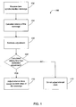
- FIG. 1 shows a method 100 for synchronizing in accordance with the invention.
- a network element being synchronized (“sync element”) receives a sync message (step 102).
- the sync element includes an internal clock which is being synchronized with another clock of the network, such as a master clock of the network.
- the sync message includes a time stamp of, for example, the master clock. The time stamp specifies the time, as indicated by the master clock, when the sync message was sent.
- the sync message can be sent in response to a request for synchronization (“request”) generated by the sync element or, alternatively, in response to a command from a network component such as a controller.
- request request for synchronization
- the sync element calculates the latency of the sync message (step 104).
- the element can calculate the latency by various methods. One method is to calculate a round trip time for a message to travel between the sync element and a source of the sync message.
- the source is usually a network element that includes the clock, such as the master clock, with which the internal clock of the synch element is being synchronized. Such a clock will be referred to in this specification as the reference clock. If the source is not a network element that does not include a reference clock, then the latency between the source and reference clock should be calculated and considered in the latency calculation described here.
- the sync element sends its own message, which can be the above mentioned request for synchronization, to the source of the sync message.
- the sync element marks the times, as indicated by its internal clock, of when the sync element sends the request and of when the source sends the sync message. The difference between these times is the latency involved in requesting and receiving the particular sync message received in step 102.
- the system uses the request to both trigger synchronization and to calculate round trip latency.
- the sync element can send a message that will be used to only calculate latency and is separate from the request. This type of message will be referred to as a latency calculation message.
- the sync element after it receives the sync message, sends the latency calculation message to the source of the sync message. Upon receiving the latency calculation message, the source returns the message to the sync element.
- the sync element marks the times, as indicated by its internal clock, of when the sync element sent and received the latency calculation message. When the sync element performs the described method immediately after receiving the sync message, the difference between the described times is a close approximation of the latency of the sync message.
- the source is usually a network element having the master clock but need not be.
- the sync element estimates the adjustment that will be made to its internal clock (step 106).
- the sync element can estimate the adjustment by various methods.
- One method is for the sync element to estimate the current time as indicated by the master clock, i.e., the current time of the master clock, by using the time stamp of the sync message.
- the sync element calculates the difference between the current time as indicated by its internal clock, i.e., the current time of the internal clock, and the estimated current time of the master clock to derive the estimated adjustment.
- the sync element can use other methods for estimating the adjustment. For example, instead of using the current time to estimate adjustment, the sync element can use a time of any known event, such as when the sync element receives the sync message.
- the sync element calculates the difference between the current time of the master clock and the current time of the internal clock or whether the sync element calculates the difference between the time of a known event, the difference in either case indicates the estimated adjustment to synchronize the internal clock with the master clock.
- the sync element determines if the calculated latency, which as described can approximately be the round trip time, is less than the estimated adjustment (decision 108). If it is, then the sync element adjusts its internal clock (step 110). In this case, adjustment will very likely result in an improvement of synchronization. That is, the time difference between the master clock and the internal clock of the element will be reduced. If the latency is not less than the estimated adjustment, then the element does not adjust its internal clock (step 112). In this case, an adjustment will likely not result in an improvement of synchronization because the margin of error in the synchronization calculation, as caused by the latency, is greater than the required estimated adjustment.
- a wireless network is a telemetry system that includes a system controller ("SC"), one or more master controllers ("MCC”), and one or more terminal units.
- SC system controller
- MCC master controllers
- the system controller includes a master clock and each MCC includes an internal clock.
- the SC and the MCC must synchronize to, e.g., perform operations at the terminal units.
- This telemetry system is further described in commonly owned U.S. Patent No. 6,195,018 to Ragle et al., issued on February 27, 2001 , and also in commonly owned U.S. Patent Application No. 10/128,928 , entitled Intelligent Two-way Telemetry , filed on April 22, 2002.
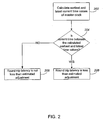
- FIG. 2 shows an example of how to determine whether calculated latency, whether balanced or not, is less than the estimated adjustment.
- a sync element such as one of the described MCCs, sends a message requesting synchronization to an element having a master clock ("master clock element"), such as the described SC.
- master clock element sends a sync message back to the network element (i.e., the synch element).
- the sync element receives the sync message.
- the sync element calculates the round trip time, which includes the time required for the request to travel from the sync element to the source, for the source to process the request and respond, and for the sync message to travel from the source to the sync element.
- the round-trip time in this example, represents the latency.
- the synch element calculates the earliest and latest time values of the current time of the master clock, assuming a completely imbalanced latency (step 202).
- the earliest current time of the master clock results from one extreme case of imbalanced latency where all of the latency is caused by the time it takes for a request message to travel from the sync element to the master clock element.
- the earliest current time of the master clock is the time stamp of the synch message.
- the latest current time of the master clock results from the other extreme case of imbalanced latency where all of the latency is caused by the time it takes for a synch message to travel from the master clock element to the sync element.
- the latest current time of the master clock is the time stamp of the synch message plus the calculated latency.
- the sync element determines if the current time, as indicated by its internal clock, is between the calculated earliest and latest time values of the current time of the master clock (decision 204). If the current time as indicated by its internal clock is between the calculated earliest and latest time values of the current time of the master clock, then the calculated latency is less than the estimated adjustment (step 206). Otherwise, the calculated latency is not less than the estimated adjustment (step 208).
- decision 204 can include additional conditions to preclude adjustment when the estimated adjustment is very small such that any adjustment will likely be detrimental to synchronization. This is the case where the internal clock of the synch element is closely synchronized with the master clock. An example of the conditions is that the time of the synch element is not within a certain band of an estimated master clock time.
- FIG. 3 shows a time line that graphically illustrates the concept of the above example.
- the band of time 302 represents the interval where the internal clock of the synch element is closely synchronized with the master clock and adjustment would likely not result in an improvement of synchronization.
- the bands of time 304 and 306 represent the interval in which if the current time of the synch element falls, then the round trip latency is less than the estimated adjustment but the internal clock of the synch element is not too closely synchronized with the master clock. When the current time of the synch element falls within this band, adjustment is likely to improve on synchronization.
- the bands of time 308 and 310 represent time intervals where the round trip latency is greater than estimated adjustment, and adjustment would likely be detrimental to synchronization.
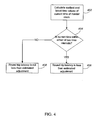
- FIG. 4 shows an example of how to determine whether round trip latency is less than the estimated adjustment when the round trip time is greater than the threshold round trip latency. This is the case where conventional synchronization techniques would discard a sync message.
- the sync element calculates the earliest and latest time values of the current time of the master clock assuming a completely imbalanced latency (step 402). This calculation is similar to the one described for step 202 of FIG. 2 .
- the sync element determines whether the current time as indicated by its internal clock is within either of two time intervals (decision 404).
- the first interval lies between the earliest current time of the master clock minus a maximum adjustment band and the earliest current time of the master clock.
- the second interval lies between the latest current time of the master clock and the latest current time of the master clock plus the maximum adjustment band.
- the maximum adjustment band delimits adjustment thresholds, beyond which adjustment will very likely cause network errors. That is, adjustment will break the network. If the current time as indicated by the sync element's internal clock lies within these two time intervals, then the round trip value is less than the estimated adjustment and adjustment is likely to improve synchronization (step 406).
- the round trip value is not less than the estimated adjustment and adjustment is likely to not improve synchronization (step 408).
- the described two time intervals can be expanded to include the interval between them. That is, the two time intervals can be substituted with one time interval delimited by the earliest and the latest times of the two time intervals. With this option, adjustment will still improve synchronization.
- FIG. 5 shows a time line that graphically illustrates the concept of the example of FIG. 4 .
- the bands of time 502 and 504 represent the described first and second time interval, respectively.
- the bands 506 and 508 of time represent the time intervals where synchronization will likely not be improved.
- the band of time 510 represents the optionally included time interval described above.
- Table 1 shows an example of pseudo code for implementing the described methods.
- the bands of FIGs. 2 through 5 correspond to those defined by the pseudo code.
- the following definition of terms apply to the pseudo code and to the figures. (The MCC is a synch element and the SC is the master clock element.)
- the logic of the pseudo code is based on the fact that as long as error margin (i.e., RT/2) is less than the amount of estimated correction ( ⁇ t), it is an improvement to adjust the MCC's internal clock (i.e., update the RTC). However, RTC is updated not to SCt estimated but either to SCt response or to (SCt response + Rt). This logic reduces the effect of error margin in the updated RTC and avoids larger fluctuations in subsequent updates. Alternatively, RTC can be set to any point between SCt response and (SCt response + Rt) and would still be an improvement over the current RTC value. Although it is not guaranteed, any point between RTC current value and SCt estimated can also be an improvement.
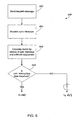
- FIG. 6 shows method 600, which is one implementation of method 100.
- An MCC of a wireless network sends a request message to a SC of the network (step 602).
- the MCC includes an internal clock and the SC includes a master clock.
- the internal clock of the MCC is being synchronized with the master clock of the SC.
- the SC sends a synch message, which the MCC receives (step 604).
- the sync message here includes a time stamp that indicates the time, as indicated by the master clock, when the SC sent the synch message.
- the MCC estimates the adjustment to the internal clock to synchronize it with the master clock (step 606).
- the MCC calculates the round trip latency (step 606), which includes the time for the request to travel from the MCC to the SC, the time required by the SC to process and respond to the request, and the time for the sync message to travel from the SC to the MCC.
- the MCC determines whether the latency is less than a threshold, such as a fixed threshold for latency that is typically used by conventional systems (decision 608).
- the MCC calculates the earliest and latest time, as indicated by the master clock, when the MCC received the sync message (step 610).
- the earliest time is the time indicated by the time stamp. This calculation assumes that the time required for the request to travel from the MCC to the SC is zero and, furthermore, that the time required for the sync message to travel from the SC to the MCC is the calculated latency.
- the latest time is the time indicated by the time stamp plus the calculated latency.
- the MCC determines if the time, as indicated by the internal clock of the MCC, when the MCC receives the sync message (i.e., MSCt response ) is between the calculated latest and earliest time (decision 612). If no, then the calculated latency is not less than the estimated adjustment (step 614) and the MCC does not adjust its internal clock (step 616).
- the MCC determines whether the time, as indicated by the internal clock, when the MCC received the sync message is within five seconds of the time, as indicated by the master clock, of when the SC sent the sync message (decision 620). If the times are within five seconds, then the MCC does not adjust its internal clock (step 616). Otherwise, the MCC adjusts its internal clock.
- the MCC calculates the earliest and latest time, as indicated by the master clock, when the MCC received the sync message (step 624). The calculation is similar to that described in reference to step 610.
- the MCC determines if the time, as indicated by the internal clock of the MCC, when the MCC receives the sync message (i.e., MSCt response ) falls within either of two time intervals (decision 626). The time intervals are similar to those described in reference to step 404 of FIG. 4 . If no, then the calculated latency is not less than the estimated adjustment (step 628) and the MCC does not adjust its internal clock (step 616). Otherwise, the calculated latency is less than the estimated adjustment (step 630) and the MCC adjusts its internal clock (step 622).
- the MCC does not estimate adjustment based on the difference between the current times of the MCC and the SC. Rather, the MCC estimates adjustment based on the time when the MCC receives the sync message. With either case, the difference should be the same, or at least very similar, and can be used to adjust the internal clock of the MCC.
- the MCC of the wireless network described above receives a sync message with a time stamp of 988970423 (in seconds) from the SC.
- the round trip time associated with the sync message is 40 seconds and the maximum predefined latency threshold is 30 seconds.
- the current time of the MCC's internal clock is 988970603.
- a conventional system would discard this sync message. Consequently, the MCC would still be 3 minutes off from the master clock of the SC.
- the systems described herein would however not discard the sync message and, by applying the described techniques, improve synchronization.
- the SC's current time (as of when the MCC receives the sync message) can be 988970423 or 988970463. Adjustment to either of this time will bring the internal clock closer to the time of the master clock.
- the invention can be implemented in digital electronic circuitry, or in computer hardware, firmware, software, or in combinations of them.
- Apparatus of the invention can be implemented in a computer program product tangibly embodied in a machine-readable storage device for execution by a programmable processor; and method steps of the invention can be performed by a programmable processor executing a program of instructions to perform functions of the invention by operating on input data and generating output.
- the invention can be implemented advantageously in one or more computer programs that are executable on a programmable system including at least one programmable processor coupled to receive data and instructions from, and to transmit data and instructions to, a data storage system, at least one input device, and at least one output device.
- Each computer program can be implemented in a high-level procedural or object-oriented programming language, or in assembly or machine language if desired; and in any case, the language can be a compiled or interpreted language.
- Suitable processors include, by way of example, both general and special purpose microprocessors.
- a processor will receive instructions and data from a read-only memory and/or a random access memory.
- the essential elements of a computer are a processor for executing instructions and a memory.
- a computer will include one or more mass storage devices for storing data files; such devices include magnetic disks, such as internal hard disks and removable disks; magneto-optical disks; and optical disks.
- Storage devices suitable for tangibly embodying computer program instructions and data include all forms of non-volatile memory, including by way of example semiconductor memory devices, such as EPROM, EEPROM, and flash memory devices; magnetic disks such as internal hard disks and removable disks; magneto-optical disks; and CD-ROM disks. Any of the foregoing can be supplemented by, or incorporated in, ASICs (application-specific integrated circuits).
- semiconductor memory devices such as EPROM, EEPROM, and flash memory devices
- magnetic disks such as internal hard disks and removable disks
- magneto-optical disks magneto-optical disks
- CD-ROM disks CD-ROM disks
- Bands 304 and 306 need not be delimited as described but can also be otherwise delimited and still improve synchronization.
- the bands 304 and 306 of FIG. 3 and as defined in Table 1 can be increased to and area delimited by (SCt estimated - CtsRtcMaxUpdate) and (SCt estimated + CtsRtcMaxUpdate).
- the clock with which the internal clock of the sync element is being synchronized need not be a master clock but can be any clock of the network.
- the network refers to a set of elements connect by one or more links.
- the network can include multiple networks.
- the network can include two enterprise networks linked by the Internet.
Landscapes
- Engineering & Computer Science (AREA)
- Theoretical Computer Science (AREA)
- Computer Networks & Wireless Communication (AREA)
- Signal Processing (AREA)
- Physics & Mathematics (AREA)
- General Engineering & Computer Science (AREA)
- General Physics & Mathematics (AREA)
- Synchronisation In Digital Transmission Systems (AREA)
- Stabilization Of Oscillater, Synchronisation, Frequency Synthesizers (AREA)
- Electric Clocks (AREA)
Abstract
Description
- This invention relates to time synchronization over a network.
- A network generally includes elements that may need to coordinate their operations. When coordination is required, some of these elements have internal clocks that are synchronized with a master clock. One technique for synchronizing is to periodically send messages from the master clock to the network elements. These messages include a time value that the master clock provides (i.e., a time stamp). An element receiving one of the messages estimates the master clock time by calculating any delay between the time the master clocks stamps the message and when the element processes the message and by adding the calculated delay to the time stamp of the message. The element then can adjust, i.e., synchronize, its internal clock to match the estimated time of the master clock. The mentioned delay is often referred to as latency.
- One source of latency is the time it takes for the message to travel from the master clock to the element. One way for an element to calculate this travel time is to send a message on a round trip to the master clock and then measure the time it takes the message to return. The element then splits the round trip time to calculate the time it takes for the message to travel from the master clock to the element.
- There are usually thresholds beyond which adjustments to the internal clock of an element being considered may not improve synchronization with the master clock. One such threshold is a margin of error with which a network element can estimate the time of the master clock. The described latency is a significant contributor to this margin of error. Conventional synchronization schemes define a preset set value of latency beyond which the margin of error will be too great to synchronize. An element will thus discard a time synchronization message having latency that is greater than the preset value.
- Another threshold is a maximum which a network element can change its internal clock without breaking the network. In this case, the element is able to accurately estimate the time of the master clock but the element's internal clock is so much out of sync with the master clock that adjustment will result in errors in the network. Conventional synchronization schemes also define a preset value for this threshold of maximum adjustment.
- Document
US5276659 discloses a clock synchronization system which synchronizes a master station and a number of slave stations. The system monitors the time difference between the reference time of the master station and the current time of the slave stations. When the time difference exceeds a predetermined value, the system divides the time difference by a predetermined correction number to determine time correction coefficient. The system then corrects the time of the slave station using the time correction coefficient. - Document
US5535217 discloses a probabilistic clock synchronization scheme for synchronization of five clocks between nodes on a communication network. The scheme use round trip clock synchronization and a system of intersecting intervals to calculate clock correction. - The present invention provides methods and apparatus, including computer program products, for synchronizing a network using dynamic thresholds.
- In general, in one aspect, a method for synchronizing an internal clock of a network element with a master clock of a master clock element, the method comprising: receiving at said network element a time synchronization message sent from said master clock element, and; calculating a latency of the time synchronization message; characterised in that the method further comprises: estimating an adjustment that may be made to the internal clock in response to the time synchronization message; determining whether the calculated latency of the time synchronization message is less than the adjustment estimated; and adjusting the internal clock when the calculated latency of the time synchronization message is less than the adjustment estimated..
- In general, in another aspect, a computer program product, adapted to perform a method for synchronizing a first clock of a network with a second clock of the network, the product comprising instructions to cause a processor to: calculate a latency of a time synchronisation message, received by the first clock from the second clock; characterised in that the product further comprises instructions to cause a processor to: estimate an adjustment of the first clock to synchronize the first clock with the second clock; and determine whether to adjust the first clock, the determining being based on whether the latency calculated is less than the adjustment estimated.
- In general, in another aspect, a computer program product, for synchronizing a first clock of a network with a second clock of the network, includes instructions to cause a processor to calculate a latency of a time synchronisation message, received by the first clock from the second clock. The product includes instructions to estimate an adjustment of the first clock to synchronize the first clock with the second clock. The product includes instructions to calculate an earliest current time as indicated by the second clock and a latest current time as indicated by the second clock, the calculation assuming that the latency is completely imbalanced. The product includes instructions to determine that the latency calculated is less than the adjustment estimated when a current time as indicated by the first clock is in between the earliest and latest current times. The product is tangibly stored on machine-readable medium.
- Particular implementations of the invention can provide any combination of the following features. A system in accordance with the invention uses dynamic thresholds to determine whether to adjust an internal clock of a network element being considered for synchronization. The system need not rely on a preset acceptable error margin and can improve synchronization where conventional systems would discard a time synchronization message. The system can accommodate balanced as well as unbalanced latency. Balanced latency occurs when the travel time of each leg of a round trip is the same. Unbalanced latency occurs when the travel for each leg is different. The system can accommodate latency that is variable, such as latency that occurs in networks having elements that communicate by wireless transmission and reception, such as radio frequency ("RF") transmission and reception. The dynamic thresholds can account for variables, such as the described latency, for each instance of synchronization.
- The details of one or more implementations are set forth in the accompanying drawings and the description below. Other features and advantages will be apparent from the description and drawings.
-
-
FIG. 1 shows a method for synchronizing one clock of a network with another clock of the network. -
FIG. 2 shows an example of how to determine whether the round trip latency between the clocks being synchronized is less than an estimated adjustment to one of the clocks. -
FIG. 3 graphically illustrates the concept of the example ofFIG. 2 . -
FIG. 4 shows another example of how to determine whether round the trip latency between the clocks being synchronized is less than the estimated adjustment to one of the clocks. -
FIG. 5 graphically illustrates the concept of the example ofFIG. 4 . -
FIG. 6 shows an implementation of themethod 100. - Like reference symbols in the various drawings indicate like elements.
- Time synchronization techniques in accordance with the invention uses the fact that as long as the latency of a time synchronization message ("sync message") received by a network element is less than an estimated amount of correction of an internal clock of the network element, it is an improvement to adjust the internal clock. Adjustment in such cases brings the time of the internal clock closer in synch to the time of another clock, such as a master clock of the network, with which the internal clock is being synchronized. The techniques adopt a methodology in which a calculation of the acceptable margin of error is dynamically related to the estimated correction. The acceptable margin of error is not a preset value.
-
FIG. 1 shows amethod 100 for synchronizing in accordance with the invention. A network element being synchronized ("sync element") receives a sync message (step 102). The sync element includes an internal clock which is being synchronized with another clock of the network, such as a master clock of the network. The sync message includes a time stamp of, for example, the master clock. The time stamp specifies the time, as indicated by the master clock, when the sync message was sent. The sync message can be sent in response to a request for synchronization ("request") generated by the sync element or, alternatively, in response to a command from a network component such as a controller. - The sync element calculates the latency of the sync message (step 104). The element can calculate the latency by various methods. One method is to calculate a round trip time for a message to travel between the sync element and a source of the sync message. The source is usually a network element that includes the clock, such as the master clock, with which the internal clock of the synch element is being synchronized. Such a clock will be referred to in this specification as the reference clock. If the source is not a network element that does not include a reference clock, then the latency between the source and reference clock should be calculated and considered in the latency calculation described here. In this round-trip time method, the sync element sends its own message, which can be the above mentioned request for synchronization, to the source of the sync message. The sync element marks the times, as indicated by its internal clock, of when the sync element sends the request and of when the source sends the sync message. The difference between these times is the latency involved in requesting and receiving the particular sync message received in
step 102. In this case, the system uses the request to both trigger synchronization and to calculate round trip latency. - Alternatively, the sync element can send a message that will be used to only calculate latency and is separate from the request. This type of message will be referred to as a latency calculation message. In this case, the sync element, after it receives the sync message, sends the latency calculation message to the source of the sync message. Upon receiving the latency calculation message, the source returns the message to the sync element. The sync element marks the times, as indicated by its internal clock, of when the sync element sent and received the latency calculation message. When the sync element performs the described method immediately after receiving the sync message, the difference between the described times is a close approximation of the latency of the sync message.
- As an alternative to the round-trip time method, other techniques can be used to determine the latency of the sync message. As discussed, the source is usually a network element having the master clock but need not be.
- The sync element estimates the adjustment that will be made to its internal clock (step 106). The sync element can estimate the adjustment by various methods. One method is for the sync element to estimate the current time as indicated by the master clock, i.e., the current time of the master clock, by using the time stamp of the sync message. Then, the sync element calculates the difference between the current time as indicated by its internal clock, i.e., the current time of the internal clock, and the estimated current time of the master clock to derive the estimated adjustment. Alternatively, the sync element can use other methods for estimating the adjustment. For example, instead of using the current time to estimate adjustment, the sync element can use a time of any known event, such as when the sync element receives the sync message. Regardless of whether the sync element calculates the difference between the current time of the master clock and the current time of the internal clock or whether the sync element calculates the difference between the time of a known event, the difference in either case indicates the estimated adjustment to synchronize the internal clock with the master clock.
- The sync element determines if the calculated latency, which as described can approximately be the round trip time, is less than the estimated adjustment (decision 108). If it is, then the sync element adjusts its internal clock (step 110). In this case, adjustment will very likely result in an improvement of synchronization. That is, the time difference between the master clock and the internal clock of the element will be reduced. If the latency is not less than the estimated adjustment, then the element does not adjust its internal clock (step 112). In this case, an adjustment will likely not result in an improvement of synchronization because the margin of error in the synchronization calculation, as caused by the latency, is greater than the required estimated adjustment.
- Although any network requiring synchronization will benefit from the
method 100, this method especially benefits those networks having imbalanced latency such as wireless networks. An example of a wireless network is a telemetry system that includes a system controller ("SC"), one or more master controllers ("MCC"), and one or more terminal units. The system controller includes a master clock and each MCC includes an internal clock. The SC and the MCC must synchronize to, e.g., perform operations at the terminal units. This telemetry system is further described in commonly ownedU.S. Patent No. 6,195,018 to Ragle et al., issued on February 27, 2001 , and also in commonly ownedU.S. Patent Application No. 10/128,928 -
FIG. 2 shows an example of how to determine whether calculated latency, whether balanced or not, is less than the estimated adjustment. In this example, a sync element, such as one of the described MCCs, sends a message requesting synchronization to an element having a master clock ("master clock element"), such as the described SC. In response, the master clock element sends a sync message back to the network element (i.e., the synch element). The sync element receives the sync message. The sync element calculates the round trip time, which includes the time required for the request to travel from the sync element to the source, for the source to process the request and respond, and for the sync message to travel from the source to the sync element. The round-trip time, in this example, represents the latency. - To determine whether calculated latency is less than the estimated adjustment, the synch element calculates the earliest and latest time values of the current time of the master clock, assuming a completely imbalanced latency (step 202). The earliest current time of the master clock results from one extreme case of imbalanced latency where all of the latency is caused by the time it takes for a request message to travel from the sync element to the master clock element. In this extreme case, the earliest current time of the master clock is the time stamp of the synch message. The latest current time of the master clock results from the other extreme case of imbalanced latency where all of the latency is caused by the time it takes for a synch message to travel from the master clock element to the sync element. In this extreme case, the latest current time of the master clock is the time stamp of the synch message plus the calculated latency.
- The sync element determines if the current time, as indicated by its internal clock, is between the calculated earliest and latest time values of the current time of the master clock (decision 204). If the current time as indicated by its internal clock is between the calculated earliest and latest time values of the current time of the master clock, then the calculated latency is less than the estimated adjustment (step 206). Otherwise, the calculated latency is not less than the estimated adjustment (step 208).
- Optionally,
decision 204 can include additional conditions to preclude adjustment when the estimated adjustment is very small such that any adjustment will likely be detrimental to synchronization. This is the case where the internal clock of the synch element is closely synchronized with the master clock. An example of the conditions is that the time of the synch element is not within a certain band of an estimated master clock time. -
FIG. 3 shows a time line that graphically illustrates the concept of the above example. The band oftime 302 represents the interval where the internal clock of the synch element is closely synchronized with the master clock and adjustment would likely not result in an improvement of synchronization. The bands oftime time - The example described in reference to
FIGs. 2 and3 represents the case where the round trip latency is less than some preset threshold, such as the preset value of latency mentioned in the background section.FIG. 4 shows an example of how to determine whether round trip latency is less than the estimated adjustment when the round trip time is greater than the threshold round trip latency. This is the case where conventional synchronization techniques would discard a sync message. - To determine whether round trip latency is less than the estimated adjustment, the sync element calculates the earliest and latest time values of the current time of the master clock assuming a completely imbalanced latency (step 402). This calculation is similar to the one described for
step 202 ofFIG. 2 . - The sync element determines whether the current time as indicated by its internal clock is within either of two time intervals (decision 404). The first interval lies between the earliest current time of the master clock minus a maximum adjustment band and the earliest current time of the master clock. The second interval lies between the latest current time of the master clock and the latest current time of the master clock plus the maximum adjustment band. The maximum adjustment band delimits adjustment thresholds, beyond which adjustment will very likely cause network errors. That is, adjustment will break the network. If the current time as indicated by the sync element's internal clock lies within these two time intervals, then the round trip value is less than the estimated adjustment and adjustment is likely to improve synchronization (step 406). Otherwise, the round trip value is not less than the estimated adjustment and adjustment is likely to not improve synchronization (step 408). Optionally, the described two time intervals can be expanded to include the interval between them. That is, the two time intervals can be substituted with one time interval delimited by the earliest and the latest times of the two time intervals. With this option, adjustment will still improve synchronization.
-
FIG. 5 shows a time line that graphically illustrates the concept of the example ofFIG. 4 . The bands oftime bands time 510 represents the optionally included time interval described above. - Table 1 shows an example of pseudo code for implementing the described methods. The bands of
FIGs. 2 through 5 correspond to those defined by the pseudo code. The following definition of terms apply to the pseudo code and to the figures. (The MCC is a synch element and the SC is the master clock element.) - MSCtrequest: The time when MCC sends a request to initiate synchronization as indicated by the internal clock of the MCC.
- MSCtresponse: The time when the MCC receives a response to its request as indicated by the internal clock of the MCC.
- SCtresponse: The time when the SC sends the response to the MCC as indicated by the master clock.
- SCtestimated: This is the estimated current time of SC as indicated by calculated by the MCC.
- RTC: Current time as indicated by the MCC's internal clock.
- Rt: Round Trip Time; the difference between MSCtrequest and MSCtresponse.
- Δt : Time difference between RTC and estimated SC time
- CtsMaxRqstMsgRoundtrip: A preset threshold specifying the maximum round trip time above which convention synchronization techniques would discard the sync message.
- CtsRtcMaxUpdate: A threshold specifying the maximum which a network element can change its internal clock without breaking the network.
- The logic of the pseudo code is based on the fact that as long as error margin (i.e., RT/2) is less than the amount of estimated correction (Δt), it is an improvement to adjust the MCC's internal clock (i.e., update the RTC). However, RTC is updated not to SCtestimated but either to SCtresponse or to (SCtresponse + Rt). This logic reduces the effect of error margin in the updated RTC and avoids larger fluctuations in subsequent updates. Alternatively, RTC can be set to any point between SCtresponse and (SCtresponse + Rt) and would still be an improvement over the current RTC value. Although it is not guaranteed, any point between RTC current value and SCtestimated can also be an improvement.
-
FIG. 6 showsmethod 600, which is one implementation ofmethod 100. An MCC of a wireless network sends a request message to a SC of the network (step 602). The MCC includes an internal clock and the SC includes a master clock. The internal clock of the MCC is being synchronized with the master clock of the SC. In response to the request, the SC sends a synch message, which the MCC receives (step 604). As with the sync messages discussed above, the sync message here includes a time stamp that indicates the time, as indicated by the master clock, when the SC sent the synch message. The MCC estimates the adjustment to the internal clock to synchronize it with the master clock (step 606). The MCC calculates the round trip latency (step 606), which includes the time for the request to travel from the MCC to the SC, the time required by the SC to process and respond to the request, and the time for the sync message to travel from the SC to the MCC. The MCC determines whether the latency is less than a threshold, such as a fixed threshold for latency that is typically used by conventional systems (decision 608). - The process flow diverges at this juncture, depending on the result of
decision 608. If the round trip latency is less than the threshold, the MCC calculates the earliest and latest time, as indicated by the master clock, when the MCC received the sync message (step 610). The earliest time is the time indicated by the time stamp. This calculation assumes that the time required for the request to travel from the MCC to the SC is zero and, furthermore, that the time required for the sync message to travel from the SC to the MCC is the calculated latency. The latest time is the time indicated by the time stamp plus the calculated latency. This calculation assumes that the time required for the request to travel from the MCC to the SC is the calculated latency and, furthermore, that the time required for the sync message to travel from the SC to the MCC is zero. The MCC determines if the time, as indicated by the internal clock of the MCC, when the MCC receives the sync message (i.e., MSCtresponse) is between the calculated latest and earliest time (decision 612). If no, then the calculated latency is not less than the estimated adjustment (step 614) and the MCC does not adjust its internal clock (step 616). Otherwise, the MCC determines whether the time, as indicated by the internal clock, when the MCC received the sync message is within five seconds of the time, as indicated by the master clock, of when the SC sent the sync message (decision 620). If the times are within five seconds, then the MCC does not adjust its internal clock (step 616). Otherwise, the MCC adjusts its internal clock. - If the latency is not less than the threshold, the MCC calculates the earliest and latest time, as indicated by the master clock, when the MCC received the sync message (step 624). The calculation is similar to that described in reference to step 610. The MCC determines if the time, as indicated by the internal clock of the MCC, when the MCC receives the sync message (i.e., MSCtresponse) falls within either of two time intervals (decision 626). The time intervals are similar to those described in reference to step 404 of
FIG. 4 . If no, then the calculated latency is not less than the estimated adjustment (step 628) and the MCC does not adjust its internal clock (step 616). Otherwise, the calculated latency is less than the estimated adjustment (step 630) and the MCC adjusts its internal clock (step 622). - In the above example, the MCC does not estimate adjustment based on the difference between the current times of the MCC and the SC. Rather, the MCC estimates adjustment based on the time when the MCC receives the sync message. With either case, the difference should be the same, or at least very similar, and can be used to adjust the internal clock of the MCC.
- The following provides an example scenario. The MCC of the wireless network described above receives a sync message with a time stamp of 988970423 (in seconds) from the SC. The round trip time associated with the sync message is 40 seconds and the maximum predefined latency threshold is 30 seconds. The current time of the MCC's internal clock is 988970603. A conventional system would discard this sync message. Consequently, the MCC would still be 3 minutes off from the master clock of the SC. The systems described herein would however not discard the sync message and, by applying the described techniques, improve synchronization. Assuming a completely imbalanced latency, the SC's current time (as of when the MCC receives the sync message) can be 988970423 or 988970463. Adjustment to either of this time will bring the internal clock closer to the time of the master clock.
- The invention can be implemented in digital electronic circuitry, or in computer hardware, firmware, software, or in combinations of them. Apparatus of the invention can be implemented in a computer program product tangibly embodied in a machine-readable storage device for execution by a programmable processor; and method steps of the invention can be performed by a programmable processor executing a program of instructions to perform functions of the invention by operating on input data and generating output. The invention can be implemented advantageously in one or more computer programs that are executable on a programmable system including at least one programmable processor coupled to receive data and instructions from, and to transmit data and instructions to, a data storage system, at least one input device, and at least one output device. Each computer program can be implemented in a high-level procedural or object-oriented programming language, or in assembly or machine language if desired; and in any case, the language can be a compiled or interpreted language. Suitable processors include, by way of example, both general and special purpose microprocessors. Generally, a processor will receive instructions and data from a read-only memory and/or a random access memory. The essential elements of a computer are a processor for executing instructions and a memory. Generally, a computer will include one or more mass storage devices for storing data files; such devices include magnetic disks, such as internal hard disks and removable disks; magneto-optical disks; and optical disks. Storage devices suitable for tangibly embodying computer program instructions and data include all forms of non-volatile memory, including by way of example semiconductor memory devices, such as EPROM, EEPROM, and flash memory devices; magnetic disks such as internal hard disks and removable disks; magneto-optical disks; and CD-ROM disks. Any of the foregoing can be supplemented by, or incorporated in, ASICs (application-specific integrated circuits).
- A number of implementations have been described. Nevertheless, it will be understood that various modifications may be made. For example, the steps of the described method can be performed in different order and still achieve the same or similar results.
Bands bands FIG. 3 and as defined in Table 1 can be increased to and area delimited by (SCtestimated - CtsRtcMaxUpdate) and (SCtestimated + CtsRtcMaxUpdate). The clock with which the internal clock of the sync element is being synchronized need not be a master clock but can be any clock of the network. The network refers to a set of elements connect by one or more links. The network can include multiple networks. For example, the network can include two enterprise networks linked by the Internet.

Claims (19)
- A method for synchronizing an internal clock of a network element with a master clock of a master clock element, the method comprising:receiving (102) at said network element a time synchronization message sent from said master clock element; characterised in that the method further comprises:calculating a latency (104) of the time synchronization message;estimating an adjustment (106) that may be made to the internal clock in response to the time synchronization message;determining (108) whether the calculated latency of the time synchronization message is less than the adjustment estimated; andadjusting (110) the internal clock when the calculated latency of the time synchronization message is less than the adjustment estimated.
- The method of claim 1, further comprising sending (602) a request message from the network element to the master clock element, the request message causing the master clock element to send the time synchronization message.
- The method of claim 2, wherein the step of calculating the latency includes:recording a time when the network element sent the request message;recording a time when the network element received the time synchronization message sent from the master clock element; andcalculating a difference between the time when the network element sent the request message and the time when the network element received the time synchronization message sent from the master clock element.
- The method of claim 3, wherein the time synchronization message includes a time stamp specifying a time, as indicated by the master clock, when the master clock element sent the time synchronization message, and wherein determining whether the calculated latency of the time synchronization message is less than the adjustment estimated includes:calculating an earliest current time (202) of the master clock assuming that there is no latency; andcalculating a latest current time (202) of the master clock by adding all of the calculated latency to the time stamp.
- The method of claim 4, wherein determining whether the calculated latency of the time synchronization message is less than the adjustment estimated includes:determining (204) whether a current time as indicated by the internal clock is between the earliest and latest current time of the master clock.
- The method of claim 1, wherein:the time synchronization message includes a time stamp specifying a time, as indicated by the master clock, when the master clock element sent the time synchronization message; andadjusting the internal clock includes adjusting based on the time stamp.
- The method of claim 1, further comprising:determining (608) whether the calculated latency of the time synchronization message exceeds a threshold;when the calculated latency of the time synchronization message does not exceed the threshold, applying a first set of criteria to determining whether the calculated latency is less than the adjustment estimated; andwhen the calculated latency exceeds the threshold, applying a second set of criteria to determining whether the calculated latency is less than the adjustment estimated.
- The method of claim 7, wherein supplying the first set of criteria includes:determining whether the difference between the master clock and the internal clock is below a predetermined amount; anddetermining whether adjustment to the internal clock will cause an error in the network.
- The method of claim 8, wherein:determining whether the master clock and the internal clock are sufficiently synchronized included determining whether a difference between a current time as indicated by the internal clock and the current time as estimated to be indicated by the master clock is less than five seconds (618); anddetermining whether adjustment to the internal clock will cause an error in the network includes determining whether there will be an error cause by adjusting the internal clock because a difference between the current time as indicated by the internal clock and the current time as estimated to be indicated by the master clock is too large.
- The method of claim 9, wherein:calculating a current time includes calculating the current time of when the network element receives the time synchronization message.
- A computer program product, adapted to perform a method for synchronizing a first clock of a network with a second clock of the network, characterised in that the product comprises instructions to cause a processor to:calculate a latency (104) of a time synchronisation message, received by the first clock from the second clock;estimate an adjustment (106) that may be made to the first clock to synchronize the first clock with the second clock; anddetermine (108) whether to adjust the first clock, the determining being based on whether the latency calculated is less than the adjustment estimated.
- The product of claim 11, further comprising instructions to:adjust (110) the first clock when a determination has been made to do so.
- The product of claim 11, further comprising instructions to:calculate an earliest current time as indicated by the second clock and a latest current time as indicated by the second clock, the calculation assuming that the latency is completely imbalanced; anddetermine that the latency calculated is less than the adjustment estimated when a current time as indicated by the first clock is in between the earliest and latest current times.
- The product of claim 11, further comprising instructions to determine that the first clock is to be adjusted when:the first clock and the second clock are not synchronized within five seconds; andadjustment does not cause an error in the network.
- The product of claim 11, further comprising instructions to determine that the latency calculated is less than the adjustment estimated when:adjustment does not cause an error in the network.
- The product of claim 11, wherein:the first clock is included in a first network element and the second clock is included in a second network element; andcalculating a latency between the first clock and the second clock includes calculating the time for a message to travel from the second network element to the first network element.
- The product of claim 16, wherein, the product further comprising instructions to:calculate a second time interval that it takes for a second message to travel from the first network element to the second network element, for the second element to process the second message, and for the second element to generate and send the first message; andassume the second time interval is the latency.
- The product of claim 11, wherein:the network is a wireless network; andthe second clock is a master clock.
- The product of claim 18, wherein:the network is a radio frequency network.
Applications Claiming Priority (5)
| Application Number | Priority Date | Filing Date | Title |
|---|---|---|---|
| US33736601P | 2001-11-30 | 2001-11-30 | |
| US337366P | 2001-11-30 | ||
| US280448 | 2002-10-25 | ||
| US10/280,448 US7352715B2 (en) | 2001-11-30 | 2002-10-25 | Time synchronization using dynamic thresholds |
| PCT/US2002/036799 WO2003049343A1 (en) | 2001-11-30 | 2002-11-14 | Time synchronization using dynamic thresholds |
Publications (3)
| Publication Number | Publication Date |
|---|---|
| EP1456987A1 EP1456987A1 (en) | 2004-09-15 |
| EP1456987A4 EP1456987A4 (en) | 2006-03-29 |
| EP1456987B1 true EP1456987B1 (en) | 2008-07-16 |
Family
ID=26960310
Family Applications (1)
| Application Number | Title | Priority Date | Filing Date |
|---|---|---|---|
| EP02792271A Expired - Lifetime EP1456987B1 (en) | 2001-11-30 | 2002-11-14 | Time synchronization using dynamic thresholds |
Country Status (8)
| Country | Link |
|---|---|
| US (1) | US7352715B2 (en) |
| EP (1) | EP1456987B1 (en) |
| AT (1) | ATE401708T1 (en) |
| AU (1) | AU2002357733A1 (en) |
| CA (1) | CA2468764C (en) |
| DE (1) | DE60227698D1 (en) |
| MX (1) | MXPA04005111A (en) |
| WO (1) | WO2003049343A1 (en) |
Families Citing this family (41)
| Publication number | Priority date | Publication date | Assignee | Title |
|---|---|---|---|---|
| US6930620B2 (en) * | 2002-01-15 | 2005-08-16 | Microsoft Corporation | Methods and systems for synchronizing data streams |
| US7555013B2 (en) * | 2002-08-12 | 2009-06-30 | Harris Corporation | Method and system for the blind determination of frequency hopping system characteristics and synchronization thereto |
| US9061207B2 (en) * | 2002-12-10 | 2015-06-23 | Sony Computer Entertainment America Llc | Temporary decoder apparatus and method |
| US7340630B2 (en) * | 2003-08-08 | 2008-03-04 | Hewlett-Packard Development Company, L.P. | Multiprocessor system with interactive synchronization of local clocks |
| AU2003294195A1 (en) * | 2003-12-30 | 2005-07-21 | Telefonaktiebolaget Lm Ericsson (Publ) | Method and system for handling context of data packet flows |
| DE102004028071B3 (en) * | 2004-06-09 | 2005-11-03 | Siemens Ag | Decentralized time interval synchronization in distributed networks |
| US8312103B2 (en) | 2006-08-31 | 2012-11-13 | Itron, Inc. | Periodic balanced communication node and server assignment |
| US7847536B2 (en) | 2006-08-31 | 2010-12-07 | Itron, Inc. | Hall sensor with temperature drift control |
| US8024724B2 (en) | 2006-08-31 | 2011-09-20 | Itron, Inc. | Firmware download |
| US8049642B2 (en) * | 2006-09-05 | 2011-11-01 | Itron, Inc. | Load side voltage sensing for AMI metrology |
| US9354083B2 (en) | 2006-09-15 | 2016-05-31 | Itron, Inc. | Home area networking (HAN) with low power considerations for battery devices |
| US8787210B2 (en) | 2006-09-15 | 2014-07-22 | Itron, Inc. | Firmware download with adaptive lost packet recovery |
| US8138944B2 (en) | 2006-09-15 | 2012-03-20 | Itron, Inc. | Home area networking (HAN) with handheld for diagnostics |
| US7843391B2 (en) | 2006-09-15 | 2010-11-30 | Itron, Inc. | RF local area network antenna design |
| US8212687B2 (en) | 2006-09-15 | 2012-07-03 | Itron, Inc. | Load side voltage sensing for AMI metrology |
| US7986718B2 (en) | 2006-09-15 | 2011-07-26 | Itron, Inc. | Discovery phase in a frequency hopping network |
| US8055461B2 (en) | 2006-09-15 | 2011-11-08 | Itron, Inc. | Distributing metering responses for load balancing an AMR network |
| US8384558B2 (en) | 2006-10-19 | 2013-02-26 | Itron, Inc. | Extending contact life in remote disconnect applications |
| US8838776B2 (en) * | 2007-09-26 | 2014-09-16 | Vega Grieshaber Kg | Method for the automatic time synchronisation of devices in network-based systems |
| WO2009055103A2 (en) * | 2007-10-22 | 2009-04-30 | Rambus, Inc. | Low-power source-synchronous signaling |
| US7961554B2 (en) * | 2008-01-11 | 2011-06-14 | Cellnet Innovations, Inc. | Methods and systems for accurate time-keeping on metering and other network communication devices |
| US7903681B2 (en) * | 2008-06-13 | 2011-03-08 | Alcatel Lucent | Method for distributing a common time reference within a distributed architecture |
| JP4572976B2 (en) * | 2008-09-26 | 2010-11-04 | ブラザー工業株式会社 | Communication device and communication program |
| JP5418003B2 (en) * | 2009-06-12 | 2014-02-19 | ソニー株式会社 | Information processing apparatus, synchronization correction method, and computer program |
| EP2449728B1 (en) * | 2009-06-30 | 2019-02-20 | D&M Holdings, Inc. | Systems and methods for providing synchronization in a networked environment |
| US8340790B2 (en) * | 2009-08-31 | 2012-12-25 | Fisher-Rosemount Systems, Inc. | Methods and apparatus to adjust control loop timing in a process control system |
| WO2011136705A1 (en) * | 2010-04-26 | 2011-11-03 | Telefonaktiebolaget L M Ericsson (Publ) | Method for setting and adjusting a parameter dependent on a round trip time |
| US8675689B2 (en) * | 2011-02-15 | 2014-03-18 | General Electric Company | Method of time synchronization of free running nodes in an avionics network |
| US10200476B2 (en) | 2011-10-18 | 2019-02-05 | Itron, Inc. | Traffic management and remote configuration in a gateway-based network |
| US9419888B2 (en) | 2011-12-22 | 2016-08-16 | Itron, Inc. | Cell router failure detection in a mesh network |
| US8751757B1 (en) * | 2011-12-30 | 2014-06-10 | Emc Corporation | Acquisition and kernel memory storage of I/O metrics |
| US9547332B1 (en) | 2012-03-21 | 2017-01-17 | Marvell Israel (M.I.S.L) Ltd. | Accurate time capture and transfer between clock domains |
| US12541793B2 (en) | 2012-12-18 | 2026-02-03 | Trading Technologies International, Inc. | Methods and systems to prevent adverse exchange limit effects |
| US10049404B2 (en) | 2012-12-18 | 2018-08-14 | Trading Technologies International, Inc. | Methods and systems to prevent adverse exchange limit effects |
| US9510286B2 (en) * | 2013-03-27 | 2016-11-29 | Qualcomm Incorporated | Systems and methods for synchronization within a neighborhood aware network |
| CN104981742B (en) * | 2013-06-12 | 2017-09-19 | 富士电机株式会社 | Distribution device, distribution system and distribution method |
| US10853435B2 (en) * | 2016-06-17 | 2020-12-01 | Axon Enterprise, Inc. | Systems and methods for aligning event data |
| US10833799B2 (en) | 2018-05-31 | 2020-11-10 | Itron Global Sarl | Message correction and dynamic correction adjustment for communication systems |
| US11449090B2 (en) * | 2019-06-10 | 2022-09-20 | Ford Global Technologies, Llc | Synchronizing sensing systems |
| US11137794B2 (en) * | 2020-01-06 | 2021-10-05 | Woodward, Inc. | Systems and methods for synchronization of multiple processors |
| EP3866019B1 (en) * | 2020-02-17 | 2025-01-01 | STMicroelectronics (Grenoble 2) SAS | Clock-error estimation for two-clock electronic device |
Family Cites Families (19)
| Publication number | Priority date | Publication date | Assignee | Title |
|---|---|---|---|---|
| US4882739A (en) * | 1988-01-26 | 1989-11-21 | Computer Sports Medicine, Inc. | Method for adjusting clocks of multiple data processors to a common time base |
| US5495482A (en) * | 1989-09-29 | 1996-02-27 | Motorola Inc. | Packet transmission system and method utilizing both a data bus and dedicated control lines |
| JPH03296684A (en) * | 1990-04-16 | 1991-12-27 | Toshiba Corp | Synchronizing system of time of network station |
| US5428645A (en) * | 1992-11-03 | 1995-06-27 | International Business Machines Corporation | Anonymous time synchronization method |
| US5689688A (en) * | 1993-11-16 | 1997-11-18 | International Business Machines Corporation | Probabilistic anonymous clock synchronization method and apparatus for synchronizing a local time scale with a reference time scale |
| US5535217A (en) * | 1994-12-20 | 1996-07-09 | International Business Machines Corporation | Method and apparatus for probabilistic clock synchronization with interval arithmetic |
| US6195018B1 (en) * | 1996-02-07 | 2001-02-27 | Cellnet Data Systems, Inc. | Metering system |
| US6069887A (en) * | 1997-05-28 | 2000-05-30 | Apple Computer, Inc. | Method and system for synchronization in a wireless local area network |
| SE509836C2 (en) * | 1997-06-13 | 1999-03-15 | Ericsson Telefon Ab L M | Procedure and arrangement in a radio communication system |
| US6373834B1 (en) * | 1997-12-19 | 2002-04-16 | Telefonaktiebolaget Lm Ericsson | Synchronization for cellular telecommunications network |
| US6157957A (en) * | 1998-01-22 | 2000-12-05 | Cisco Technology, Inc. | Clock synchronization system and method using a continuous conversion function for a communication network |
| US6199169B1 (en) * | 1998-03-31 | 2001-03-06 | Compaq Computer Corporation | System and method for synchronizing time across a computer cluster |
| US6370161B1 (en) * | 1998-05-20 | 2002-04-09 | Aspect Communications | Time synchronization of distributed computer telephony communication applications in a computer network |
| US6347084B1 (en) * | 1998-05-28 | 2002-02-12 | U.S. Philips Corporation | Method of timestamp synchronization of a reservation-based TDMA protocol |
| US6717915B1 (en) * | 1998-07-10 | 2004-04-06 | Openwave Systems, Inc. | Method and apparatus for dynamically configuring timing parameters for wireless data devices |
| US6452962B1 (en) * | 1999-06-11 | 2002-09-17 | Trw Inc. | Mitigation of co-channel interference in synchronization bursts in a multi-beam communication system |
| US7103124B1 (en) * | 1999-12-30 | 2006-09-05 | Telefonaktiebolaget Lm Ericsson (Publ) | Synchronization of nodes |
| CA2301436A1 (en) * | 2000-03-20 | 2001-09-20 | Peter Renaud | Method and system for multi-protocol clock recovery and generation |
| US6577872B1 (en) * | 2000-08-08 | 2003-06-10 | Telefonaktiebolaget Lm Ericsson (Publ) | Base station oscillator regulation independent of transport network clocks in cellular telecommunications network |
-
2002
- 2002-10-25 US US10/280,448 patent/US7352715B2/en not_active Expired - Lifetime
- 2002-11-14 EP EP02792271A patent/EP1456987B1/en not_active Expired - Lifetime
- 2002-11-14 DE DE60227698T patent/DE60227698D1/de not_active Expired - Lifetime
- 2002-11-14 WO PCT/US2002/036799 patent/WO2003049343A1/en not_active Ceased
- 2002-11-14 CA CA2468764A patent/CA2468764C/en not_active Expired - Lifetime
- 2002-11-14 AT AT02792271T patent/ATE401708T1/en not_active IP Right Cessation
- 2002-11-14 MX MXPA04005111A patent/MXPA04005111A/en active IP Right Grant
- 2002-11-14 AU AU2002357733A patent/AU2002357733A1/en not_active Abandoned
Also Published As
| Publication number | Publication date |
|---|---|
| US7352715B2 (en) | 2008-04-01 |
| MXPA04005111A (en) | 2005-04-29 |
| EP1456987A1 (en) | 2004-09-15 |
| US20030103486A1 (en) | 2003-06-05 |
| ATE401708T1 (en) | 2008-08-15 |
| AU2002357733A1 (en) | 2003-06-17 |
| DE60227698D1 (en) | 2008-08-28 |
| CA2468764A1 (en) | 2003-06-12 |
| EP1456987A4 (en) | 2006-03-29 |
| WO2003049343A1 (en) | 2003-06-12 |
| CA2468764C (en) | 2011-02-08 |
Similar Documents
| Publication | Publication Date | Title |
|---|---|---|
| CA2468764C (en) | Time synchronization using dynamic thresholds | |
| US7283568B2 (en) | Methods, systems and computer program products for synchronizing clocks of nodes on a computer network | |
| US7440474B1 (en) | Method and apparatus for synchronizing clocks on packet-switched networks | |
| US8700805B2 (en) | Method for synchronizing clocks in a communication network | |
| WO2001050674A1 (en) | Synchronization in packet-switched telecommunications system | |
| US9143251B2 (en) | Phase synchronizing nodes in a telecommunications network | |
| US6522205B2 (en) | Long term stability of an oscillator using a time source on a packet switched network | |
| JP2006081200A (en) | Method for synchronizing base stations | |
| US20040151125A1 (en) | Method for synchronization in a local area network including a store-and-forward device | |
| US7860040B2 (en) | Distributed synchronization method and system | |
| US12167353B2 (en) | Network entities and methods for a wireless network system for determining time information | |
| US11606157B1 (en) | Time synchronization based on network traffic patterns | |
| US10263760B2 (en) | Method for time synchronization | |
| CN116325979A (en) | Method and device for synchronizing devices in a wireless network | |
| JP2000174821A (en) | Method for controlling frequency via asynchronous transmission network and system therefor and mobile telephone network including the system | |
| JP7123228B1 (en) | Clock processor and program | |
| KR101775728B1 (en) | Apparatus and method for controlling network timing | |
| JP2633499B2 (en) | Network time synchronization method | |
| JP2020009165A (en) | Clock adjusting apparatus and program | |
| US20020052707A1 (en) | Communications network having a time-controlled communication protocol | |
| WO2024138223A1 (en) | Transmission of embargoed information | |
| US20100074219A1 (en) | Methods and Apparatus for Reverse Link Timing Correction | |
| JPH11225167A (en) | Digital signal receiver, its method and recording medium storing program concerning the method |
Legal Events
| Date | Code | Title | Description |
|---|---|---|---|
| PUAI | Public reference made under article 153(3) epc to a published international application that has entered the european phase |
Free format text: ORIGINAL CODE: 0009012 |
|
| 17P | Request for examination filed |
Effective date: 20040618 |
|
| AK | Designated contracting states |
Kind code of ref document: A1 Designated state(s): AT BE BG CH CY CZ DE DK EE ES FI FR GB GR IE IT LI LU MC NL PT SE SK TR |
|
| AX | Request for extension of the european patent |
Extension state: AL LT LV MK RO SI |
|
| A4 | Supplementary search report drawn up and despatched |
Effective date: 20060213 |
|
| RIC1 | Information provided on ipc code assigned before grant |
Ipc: G06F 1/14 20060101ALI20060207BHEP Ipc: H04J 3/06 20060101AFI20030614BHEP Ipc: H04B 7/26 20060101ALI20060207BHEP |
|
| 17Q | First examination report despatched |
Effective date: 20060804 |
|
| 17Q | First examination report despatched |
Effective date: 20060804 |
|
| GRAP | Despatch of communication of intention to grant a patent |
Free format text: ORIGINAL CODE: EPIDOSNIGR1 |
|
| GRAS | Grant fee paid |
Free format text: ORIGINAL CODE: EPIDOSNIGR3 |
|
| GRAA | (expected) grant |
Free format text: ORIGINAL CODE: 0009210 |
|
| RAP1 | Party data changed (applicant data changed or rights of an application transferred) |
Owner name: CELLNET INNOVATIONS, INC. |
|
| AK | Designated contracting states |
Kind code of ref document: B1 Designated state(s): AT BE BG CH CY CZ DE DK EE ES FI FR GB GR IE IT LI LU MC NL PT SE SK TR |
|
| AX | Request for extension of the european patent |
Extension state: AL LT LV MK RO SI |
|
| REG | Reference to a national code |
Ref country code: GB Ref legal event code: FG4D |
|
| REG | Reference to a national code |
Ref country code: CH Ref legal event code: EP |
|
| REF | Corresponds to: |
Ref document number: 60227698 Country of ref document: DE Date of ref document: 20080828 Kind code of ref document: P |
|
| REG | Reference to a national code |
Ref country code: IE Ref legal event code: FG4D |
|
| NLV1 | Nl: lapsed or annulled due to failure to fulfill the requirements of art. 29p and 29m of the patents act | ||
| PG25 | Lapsed in a contracting state [announced via postgrant information from national office to epo] |
Ref country code: PT Free format text: LAPSE BECAUSE OF FAILURE TO SUBMIT A TRANSLATION OF THE DESCRIPTION OR TO PAY THE FEE WITHIN THE PRESCRIBED TIME-LIMIT Effective date: 20081216 Ref country code: ES Free format text: LAPSE BECAUSE OF FAILURE TO SUBMIT A TRANSLATION OF THE DESCRIPTION OR TO PAY THE FEE WITHIN THE PRESCRIBED TIME-LIMIT Effective date: 20081027 Ref country code: NL Free format text: LAPSE BECAUSE OF FAILURE TO SUBMIT A TRANSLATION OF THE DESCRIPTION OR TO PAY THE FEE WITHIN THE PRESCRIBED TIME-LIMIT Effective date: 20080716 |
|
| PG25 | Lapsed in a contracting state [announced via postgrant information from national office to epo] |
Ref country code: AT Free format text: LAPSE BECAUSE OF FAILURE TO SUBMIT A TRANSLATION OF THE DESCRIPTION OR TO PAY THE FEE WITHIN THE PRESCRIBED TIME-LIMIT Effective date: 20080716 Ref country code: FI Free format text: LAPSE BECAUSE OF FAILURE TO SUBMIT A TRANSLATION OF THE DESCRIPTION OR TO PAY THE FEE WITHIN THE PRESCRIBED TIME-LIMIT Effective date: 20080716 Ref country code: BG Free format text: LAPSE BECAUSE OF FAILURE TO SUBMIT A TRANSLATION OF THE DESCRIPTION OR TO PAY THE FEE WITHIN THE PRESCRIBED TIME-LIMIT Effective date: 20081016 |
|
| PG25 | Lapsed in a contracting state [announced via postgrant information from national office to epo] |
Ref country code: BE Free format text: LAPSE BECAUSE OF FAILURE TO SUBMIT A TRANSLATION OF THE DESCRIPTION OR TO PAY THE FEE WITHIN THE PRESCRIBED TIME-LIMIT Effective date: 20080716 |
|
| PG25 | Lapsed in a contracting state [announced via postgrant information from national office to epo] |
Ref country code: EE Free format text: LAPSE BECAUSE OF FAILURE TO SUBMIT A TRANSLATION OF THE DESCRIPTION OR TO PAY THE FEE WITHIN THE PRESCRIBED TIME-LIMIT Effective date: 20080716 Ref country code: DK Free format text: LAPSE BECAUSE OF FAILURE TO SUBMIT A TRANSLATION OF THE DESCRIPTION OR TO PAY THE FEE WITHIN THE PRESCRIBED TIME-LIMIT Effective date: 20080716 |
|
| PLBE | No opposition filed within time limit |
Free format text: ORIGINAL CODE: 0009261 |
|
| STAA | Information on the status of an ep patent application or granted ep patent |
Free format text: STATUS: NO OPPOSITION FILED WITHIN TIME LIMIT |
|
| PG25 | Lapsed in a contracting state [announced via postgrant information from national office to epo] |
Ref country code: CZ Free format text: LAPSE BECAUSE OF FAILURE TO SUBMIT A TRANSLATION OF THE DESCRIPTION OR TO PAY THE FEE WITHIN THE PRESCRIBED TIME-LIMIT Effective date: 20080716 Ref country code: SK Free format text: LAPSE BECAUSE OF FAILURE TO SUBMIT A TRANSLATION OF THE DESCRIPTION OR TO PAY THE FEE WITHIN THE PRESCRIBED TIME-LIMIT Effective date: 20080716 |
|
| 26N | No opposition filed |
Effective date: 20090417 |
|
| PG25 | Lapsed in a contracting state [announced via postgrant information from national office to epo] |
Ref country code: MC Free format text: LAPSE BECAUSE OF NON-PAYMENT OF DUE FEES Effective date: 20081130 |
|
| REG | Reference to a national code |
Ref country code: CH Ref legal event code: PL |
|
| PG25 | Lapsed in a contracting state [announced via postgrant information from national office to epo] |
Ref country code: IT Free format text: LAPSE BECAUSE OF FAILURE TO SUBMIT A TRANSLATION OF THE DESCRIPTION OR TO PAY THE FEE WITHIN THE PRESCRIBED TIME-LIMIT Effective date: 20080716 |
|
| REG | Reference to a national code |
Ref country code: FR Ref legal event code: ST Effective date: 20090731 |
|
| PG25 | Lapsed in a contracting state [announced via postgrant information from national office to epo] |
Ref country code: IE Free format text: LAPSE BECAUSE OF NON-PAYMENT OF DUE FEES Effective date: 20081114 Ref country code: CH Free format text: LAPSE BECAUSE OF NON-PAYMENT OF DUE FEES Effective date: 20081130 Ref country code: LI Free format text: LAPSE BECAUSE OF NON-PAYMENT OF DUE FEES Effective date: 20081130 |
|
| PG25 | Lapsed in a contracting state [announced via postgrant information from national office to epo] |
Ref country code: SE Free format text: LAPSE BECAUSE OF FAILURE TO SUBMIT A TRANSLATION OF THE DESCRIPTION OR TO PAY THE FEE WITHIN THE PRESCRIBED TIME-LIMIT Effective date: 20081016 |
|
| PG25 | Lapsed in a contracting state [announced via postgrant information from national office to epo] |
Ref country code: LU Free format text: LAPSE BECAUSE OF NON-PAYMENT OF DUE FEES Effective date: 20081114 Ref country code: CY Free format text: LAPSE BECAUSE OF FAILURE TO SUBMIT A TRANSLATION OF THE DESCRIPTION OR TO PAY THE FEE WITHIN THE PRESCRIBED TIME-LIMIT Effective date: 20080716 |
|
| PG25 | Lapsed in a contracting state [announced via postgrant information from national office to epo] |
Ref country code: TR Free format text: LAPSE BECAUSE OF FAILURE TO SUBMIT A TRANSLATION OF THE DESCRIPTION OR TO PAY THE FEE WITHIN THE PRESCRIBED TIME-LIMIT Effective date: 20080716 |
|
| PG25 | Lapsed in a contracting state [announced via postgrant information from national office to epo] |
Ref country code: GR Free format text: LAPSE BECAUSE OF FAILURE TO SUBMIT A TRANSLATION OF THE DESCRIPTION OR TO PAY THE FEE WITHIN THE PRESCRIBED TIME-LIMIT Effective date: 20081017 |
|
| PG25 | Lapsed in a contracting state [announced via postgrant information from national office to epo] |
Ref country code: FR Free format text: LAPSE BECAUSE OF NON-PAYMENT OF DUE FEES Effective date: 20081130 |
|
| PGFP | Annual fee paid to national office [announced via postgrant information from national office to epo] |
Ref country code: GB Payment date: 20210922 Year of fee payment: 20 |
|
| PGFP | Annual fee paid to national office [announced via postgrant information from national office to epo] |
Ref country code: DE Payment date: 20210923 Year of fee payment: 20 |
|
| REG | Reference to a national code |
Ref country code: DE Ref legal event code: R071 Ref document number: 60227698 Country of ref document: DE |
|
| REG | Reference to a national code |
Ref country code: GB Ref legal event code: PE20 Expiry date: 20221113 |
|
| PG25 | Lapsed in a contracting state [announced via postgrant information from national office to epo] |
Ref country code: GB Free format text: LAPSE BECAUSE OF EXPIRATION OF PROTECTION Effective date: 20221113 |