EP1456532B1 - Assembly for delivering fuel and gas in air assist fuel injection systems - Google Patents
Assembly for delivering fuel and gas in air assist fuel injection systems Download PDFInfo
- Publication number
- EP1456532B1 EP1456532B1 EP02784210A EP02784210A EP1456532B1 EP 1456532 B1 EP1456532 B1 EP 1456532B1 EP 02784210 A EP02784210 A EP 02784210A EP 02784210 A EP02784210 A EP 02784210A EP 1456532 B1 EP1456532 B1 EP 1456532B1
- Authority
- EP
- European Patent Office
- Prior art keywords
- fuel
- fuel injector
- pressure regulator
- rail
- air assist
- Prior art date
- Legal status (The legal status is an assumption and is not a legal conclusion. Google has not performed a legal analysis and makes no representation as to the accuracy of the status listed.)
- Expired - Lifetime
Links
Images


Classifications
-
- F—MECHANICAL ENGINEERING; LIGHTING; HEATING; WEAPONS; BLASTING
- F02—COMBUSTION ENGINES; HOT-GAS OR COMBUSTION-PRODUCT ENGINE PLANTS
- F02M—SUPPLYING COMBUSTION ENGINES IN GENERAL WITH COMBUSTIBLE MIXTURES OR CONSTITUENTS THEREOF
- F02M69/00—Low-pressure fuel-injection apparatus ; Apparatus with both continuous and intermittent injection; Apparatus injecting different types of fuel
- F02M69/08—Low-pressure fuel-injection apparatus ; Apparatus with both continuous and intermittent injection; Apparatus injecting different types of fuel characterised by the fuel being carried by compressed air into main stream of combustion-air
-
- F—MECHANICAL ENGINEERING; LIGHTING; HEATING; WEAPONS; BLASTING
- F02—COMBUSTION ENGINES; HOT-GAS OR COMBUSTION-PRODUCT ENGINE PLANTS
- F02M—SUPPLYING COMBUSTION ENGINES IN GENERAL WITH COMBUSTIBLE MIXTURES OR CONSTITUENTS THEREOF
- F02M69/00—Low-pressure fuel-injection apparatus ; Apparatus with both continuous and intermittent injection; Apparatus injecting different types of fuel
- F02M69/04—Injectors peculiar thereto
- F02M69/042—Positioning of injectors with respect to engine, e.g. in the air intake conduit
- F02M69/045—Positioning of injectors with respect to engine, e.g. in the air intake conduit for injecting into the combustion chamber
-
- F—MECHANICAL ENGINEERING; LIGHTING; HEATING; WEAPONS; BLASTING
- F02—COMBUSTION ENGINES; HOT-GAS OR COMBUSTION-PRODUCT ENGINE PLANTS
- F02M—SUPPLYING COMBUSTION ENGINES IN GENERAL WITH COMBUSTIBLE MIXTURES OR CONSTITUENTS THEREOF
- F02M69/00—Low-pressure fuel-injection apparatus ; Apparatus with both continuous and intermittent injection; Apparatus injecting different types of fuel
- F02M69/46—Details, component parts or accessories not provided for in, or of interest apart from, the apparatus covered by groups F02M69/02 - F02M69/44
- F02M69/54—Arrangement of fuel pressure regulators
-
- F—MECHANICAL ENGINEERING; LIGHTING; HEATING; WEAPONS; BLASTING
- F02—COMBUSTION ENGINES; HOT-GAS OR COMBUSTION-PRODUCT ENGINE PLANTS
- F02B—INTERNAL-COMBUSTION PISTON ENGINES; COMBUSTION ENGINES IN GENERAL
- F02B2275/00—Other engines, components or details, not provided for in other groups of this subclass
- F02B2275/14—Direct injection into combustion chamber
-
- Y—GENERAL TAGGING OF NEW TECHNOLOGICAL DEVELOPMENTS; GENERAL TAGGING OF CROSS-SECTIONAL TECHNOLOGIES SPANNING OVER SEVERAL SECTIONS OF THE IPC; TECHNICAL SUBJECTS COVERED BY FORMER USPC CROSS-REFERENCE ART COLLECTIONS [XRACs] AND DIGESTS
- Y02—TECHNOLOGIES OR APPLICATIONS FOR MITIGATION OR ADAPTATION AGAINST CLIMATE CHANGE
- Y02T—CLIMATE CHANGE MITIGATION TECHNOLOGIES RELATED TO TRANSPORTATION
- Y02T10/00—Road transport of goods or passengers
- Y02T10/10—Internal combustion engine [ICE] based vehicles
- Y02T10/12—Improving ICE efficiencies
Definitions
- the present invention relates to air assist fuel injection systems and, more particularly, to assemblies for delivering fuel and gas to fuel pressure regulators, fuel injectors, and/or air assist fuel injectors of such air assist fuel injection systems.
- Conventional fuel injectors are configured to deliver a quantity of fuel to a combustion cylinder of an engine. To increase combustion efficiency and decrease pollutants, it is desirable to atomize the delivered fuel. Generally speaking, atomization of fuel can be achieved by supplying high-pressure fuel to conventional fuel injectors, or atomizing low pressure fuel with pressurized gas, i.e., "air assist fuel injection.”
- an air assist fuel injector is located in the head of an engine, which is adjacent a rail that houses a conventional fuel injector and also defines a mount for the air assist fuel injector.
- the conventional fuel injector and the rail are configured such that a metered quantity of fuel is delivered from the fuel injector directly to the air assist fuel injector.
- the rail includes a number of passageways that deliver pressurized air to the air assist fuel injectors. The air assist fuel injector atomizes the received fuel with the pressurized air and conveys the air and fuel mixture to the combustion chamber of the engine.
- This conventional air assist fuel injection system typically includes a fuel pressure regulator, such as a diaphragm or differential pressure regulator, which generally maintains the fuel supply pressure at an acceptable level so that proper fuel flow characteristics to and through the injectors are assured.
- the fuel pressure regulator maintains this fuel pressure at the desired level by maintaining a pressure differential between the fuel supply pressure and a reference pressure, such as the air supply pressure to the air assist fuel injector.
- the fuel pressure regulator is typically mounted on the rail of the air assist fuel injection system such that an external conduit typically communicates the pressurized gas to the fuel pressure regulator and a conduit in the rail communicates fuel to the fuel pressure regulator.
- one or more conduits within the rail deliver pressurized gas to the air assist fuel injector and fuel to the fuel injector.
- the present invention provides an assembly as defined in claim 1.
- Figure 1 illustrates a flow diagram of an air assist fuel injection system 50 in accordance with one embodiment of the present invention.
- the illustrated embodiment of the air assist fuel injection system 50 is configured for a two-stroke engine and includes one fuel injector 990 and one air assist fuel injector 911.
- Alternative embodiments of the air assist fuel injection system 50 may include more injectors 990, 911 and, depending on the specific engine application, more or fewer system components than those illustrated in Figure 1 .
- the system 50 includes four air assist fuel injectors 911 and four fuel injectors 990.
- the operation of the air assist fuel injection system 50 is first briefly described, followed by description of an assembly 100 of the air assist fuel injection system.
- pressurized gas from a compressor 914 is supplied to a rail 105 via a gas line 916.
- the rail 105 then fluidly communicates the pressurized gas to the air assist fuel injector 911 and to a fuel pressure regulator 900.
- a gas pressure regulator 920 is included in the gas supply flow path g and maintains the gas supply pressure at an essentially constant level during operation of the system 50.
- a gas pressure sensor 933 and a damping volume 921 are also included in the illustrated gas supply flow path g .
- Liquid fuel is also supplied to a cover 110 from a fuel tank 980 via a fuel line 907 by a pump 982.
- the cover 110 then fluidly communicates the fuel to the fuel injector 990 and the fuel pressure regulator 900.
- the fuel pressure regulator 900 is in the fuel supply flow path f between the fuel tank 980 and the fuel injector 990, as well as in the gas supply flow path g between the compressor 914 and the air assist fuel injector 911.
- the fuel pressure regulator 900 maintains the fuel supply pressure at a generally constant level during operation of the air assist fuel injection system 50 to ensure proper fuel flow characteristics to and through the injectors 990, 911.
- the fuel pressure regulator 900 maintains this fuel supply pressure at a constant level by maintaining a pressure differential between the fuel supply pressure and a reference pressure. Because the gas supply pressure is generally constant in the illustrated embodiment, it serves as a reference pressure by which the fuel pressure regulator 900 sets the fuel supply pressure for the injectors 990, 911. During operation of the fuel pressure regulator 900, fuel is returned from the fuel pressure regulator to the cover 110, which in turn fluidly communicates the returned fuel to the fuel tank 980 via a fuel return line 915.
- the fuel injector 990 receives the fuel from the cover 110 and then delivers a metered quantity of fuel to the air assist fuel injector 911.
- the air assist fuel injector 911 atomizes the fuel supplied from the fuel injector 990 with the pressurized gas supplied from the rail 105, and conveys the atomized mixture to a combustion chamber 1002 of an engine 1000 (see Figure 6a ).
- a throttle 902 is adjusted by an operator or computer.
- an electronic control unit (“ECU") 918 sends a signal to the fuel injector 990 and/or the air assist fuel injector 911 which decreases or increases the mass flow rate of fuel from the air assist fuel injector 911 to correspondingly increase or decrease the speed of the engine.
- the ECU 918 may: (1) instruct a solenoid of the fuel injector 990 to stay open longer; (2) instruct a solenoid of the air assist fuel injector 911 to stay open longer; and/or (3) change the delay between the respective openings of the injectors 990, 911.
- the ECU 918 controls changes in the fuel flow from the injectors 990, 911 while the fuel pressure regulator 900 maintains the fuel supply pressure at a constant level.
- the air assist fuel injection system 50 and the air assist fuel injector 911 are termed "air assist” because each preferably utilizes pressurized air to atomize liquid fuel.
- the pressure of the liquid fuel is preferably higher than that of the air.
- the air assist fuel injector 911 atomize liquid gasoline with pressurized air delivered by the rail 105, it will be realized that the air assist fuel injector 911 may atomize many other liquid combustible forms of energy with any variety of gases.
- the air assist fuel injector 911 may atomize liquid kerosene or liquid methane with pressurized gaseous oxygen, propane, or exhaust gas.
- the terms "air assist fuel injector” and “air assist fuel injection system” are terms of art, and as used herein are not intended to dictate that the air assist fuel injection system 50 or the air assist fuel injector 911 be used only with pressurized air.
- FIGS 2-14 illustrate features of one embodiment of an assembly 100 of the air assist fuel injection system 50 in accordance with the present invention.
- the assembly 100 is essentially one or more bodies configured to fluidly communicate pressurized gas and/or fuel to the fuel injector 990, the air assist fuel injector 911, and/or the fuel pressure regulator 900.
- the assembly 100 includes the rail 105, the cover 110, the fuel injector 990, and the fuel pressure regulator 900, which when assembled are readily mountable as a unit to the engine 1000 having the air assist fuel injector 911 mounted therein.
- Alternative embodiments of the assembly 100 may include more or fewer of the components of the air assist fuel injection system 50.
- an alternative embodiment of an assembly 50 in accordance with the present invention also includes the gas pressure regulator 920 and the gas pressure sensor 933.
- the assembly 100 only includes the rail 105, the fuel pressure regulator 900, and the air assist fuel injector 911.
- the assembly 100 only includes the cover 110 and the rail 105.
- the assembly 100 includes the fuel pressure regulator 900, one embodiment of which is illustrated in Figure 14 .
- the fuel pressure regulator 900 is configured to maintain the fuel supply pressure at a generally constant level to ensure proper fuel flow characteristics to and through the injectors 990, 911.
- the illustrated pressure regulator 900 includes a gas reference chamber 912 defined by a gas reference housing 917, and a fuel chamber 922 defined by a fuel housing 919.
- the gas reference chamber 912 includes a gas reference inlet 910 that receives the pressurized gas communicated by the rail 105.
- the fuel chamber 922 includes fuel inlets 927 that receive fuel communicated by the cover 110.
- the fuel enters the fuel chamber 922 via the inlets 927 and, under certain conditions described below, exits the pressure regulator 900 through a fuel outlet 1562 of a conduit 1561.
- a flexible, impermeable diaphragm 1550 is located between the gas reference chamber 912 and the fuel chamber 922.
- a stopper 1520 is attached to the diaphragm 1550 directly adjacent the inlet 1560 of the conduit 1561, and a spring 1570 is located between the gas reference housing 917 and the diaphragm 1550.
- the stopper 1520 When the force on the fuel side of the diaphragm 1550 (due to the fuel pressure in the fuel chamber 922) is less than the force on the gas side of the diaphragm (due to the gas pressure and the force of the spring), the stopper 1520 will be biased toward the inlet 1560 of the conduit 1561 such that it seals the inlet of the conduit 1561 and fuel does not flow out of the pressure regulator outlet 1562. When the stopper 1520 is in this position, the pressure regulator 900 is "closed".
- the pump 982 When the pressure regulator 900 is closed, the pump 982 will gradually increase the fuel pressure until the force on the fuel side of the diaphragm 1550 (due to the pressure of the fuel in the fuel chamber 922) is greater than the force on the gas side of the diaphragm (due to the gas pressure in the gas reference chamber 912 and the force of the spring 1570). When this occurs, the diaphragm 1550 and the attached stopper 1520 will move away from the inlet 1560 of the conduit 1561 such that the fuel flows through the conduit 1561 and out the outlet 1562 of the fuel pressure regulator 900 as indicated in Figure 14 by the fuel flow path f . As is illustrated in Figure 14 , when the stopper 1520 is not abutting the inlet 1560, the fuel pressure regulator 900 is "open" and fuel flows through the fuel pressure regulator.
- the fuel returns to the fuel tank 980 through the fuel return line 915. This decreases the head or pressure of the fuel supply to the injectors 990, 911.
- the pressure of the fuel supply will continue to decrease until the force on the fuel side of the diaphragm 1550 is less than the force on the gas side of the diaphragm 1550 such that the fuel pressure regulator 990 is closed.
- This opening and closing of the fuel pressure regulator 900 will repeatedly occur as the fuel supply pressure slightly rises and falls during operation of the system 50.
- the fuel pressure regulator 900 maintains a pressure differential between the gas supply pressure and the fuel supply pressure, where the pressure differential is proportional to the biasing force of the spring 1570.
- the pressure regulator 900 thus maintains the fuel supply pressure at a substantislly constant level, which ensures proper fuel flow charactéristics through the injectors 990, 911 at different fueling levels.
- the fuel pressure regulator 900 takes other configurations.
- the fuel pressure regulator 900 may control the fuel supply pressure based on the gas supply pressure with an electronic valvo and pressure sensor.
- Exemplary fuel pressure regulator 900 are also described in U.S. Patent Nos. 5,381,816 and 4,934,329 .
- the fuel pressure regulator 900 controls the fuel supply pressure by utilizing fuel and pressurized gas.
- One feature of the preferred assembly 100 is that it is configured to deliver pressurized gas and fuel to the fuel pressure regulator 900 such that the fuel pressure regulator can maintain the pressure differential between the pressurized fuel supply and the pressurized gas supply.
- the cover 110 of the assembly 100 fluidly communicates the liquid fuel to the fuel pressure regulator 900, and the rail 105 of the assembly 100 fluidly communicates the pressurized gas to the fuel pressure regulator.
- the rail 105 is a body that is configured to mount directly against, adjacent to, or generally near the head 1002 of the engine 1000 (See Figure 6a ). As is illustrated in Figures 2-12 , the rail 105 includes a cavity 977 that receives at least a portion of the fuel pressure regulator 900.
- the cavity 977 is a recess, indentation, bore, or other area capable of receiving a portion of the fuel pressure regulator 900, preferably at least a portion of the gas reference housing 917 having the gas reference inlet 910.
- the rail 105 includes an internal conduit 155, which is a channel, duct, tunnel, or other passageway inside the periphery of the rail that fluidly communicates pressurized gas from a gas inlet 504 of the rail to the cavity 977.
- the conduit 155 is a cylindrical and elongated bore within the body of the rail 105.
- the rail 105 includes a plurality of separate conduits 155 that fluidly communicate pressurized gas to the fuel pressure regulator 900.
- the fuel is supplied to the fuel pressure regulator 900 by the cover 110, which is essentially a lid, top, cap, overlay, or other body configured to cover at least a portion of the fuel pressure regulator 900 and to fluidly communicate pressurized fuel to the fuel pressure regulator 900.
- the cover 110 also includes a cavity 160 that receives at least a portion of the fuel pressure regulator 900, preferably the portion of the fuel housing 919 having the fuel inlets 927.
- the cover 110 includes internal conduits 161, 161a inside the periphery of the cover that fluidly communicate fuel from a fuel inlet 507 of the cover to the cavity 160.
- the fuel enters the fuel inlet 507 of the cover 110 from the fuel line 907, and the internal conduits 161, 161a communicate the fuel to the cavity 160 that receives the fuel pressure regulator 900. Because the fuel inlets 927 of the fuel pressure regulator 900 are located within the cavity 160, fuel communicated to the cavity by the conduits 161 will enter the fuel chamber 922 of the fuel pressure regulator for use by the fuel pressure regulator as described above.
- the cover 110 includes three internal conduits 161, 161a that each communicate fuel to the fuel pressure regulator 900.
- the cover 110 includes more or fewer of the conduits 161.
- the cover 110 includes only one conduit 161 that fluidly communicates fuel to the fuel pressure regulator.
- the cover 110 includes four conduits 161 that each fluidly communicate fuel to the fuel pressure regulator 900.
- the cover 110 is further configured to fluidly communicate pressurized fuel from the fuel outlet 1562 of the fuel pressure regulator 900.
- the cover 110 also includes a cavity 162 that receives at least a portion of the fuel pressure regulator 900, preferably the portion of the fuel housing 919 having the outlet 1562.
- the cover 110 includes another internal conduit 163 inside the periphery of the cover and that fluidly communicates fuel from the cavity 162 to a fuel outlet 505 of the cover 110.
- the fuel exiting the outlet 1562 of the fuel pressure regulator 900 enters the cavity 162, where it is then communicated by the conduit 163 to the fuel outlet 505 of the cover 110, which in turn communicates the fuel to the fuel return line 915 for eventual delivery to the fuel tank 980.
- the cavities 160,162 are preferably cylindrical bores extending into the body of the cover 110, where the diameter of the cavity 162 is less than that of the cavity 160.
- the cover 110 also fluidly communicates fuel to the fuel injector 990 and preferably covers at least a portion of the fuel injector.
- the cover 110 includes a further cavity 164 that receives at least a portion of the fuel injector 990, preferably the portion of the fuel injector 990 having an inlet 991 that receives the fuel.
- the internal conduit 161 of the cover 110 extends from the inlet 507 of the cover 110 to the cavity 164 such that the internal conduit 161 fluidly communicates fuel from the inlet to the cavity 164.
- the fuel injector 990 is a top-feed type fuel injector, such as the Deka IV Standard injector, commercially available from SIEMENS.
- the cover 110 is configured to fluidly communicate fuel to differently configured fuel injectors, such as side-feed type fuel injectors and bottom-feed type fuel injectors.
- the conduit 161 fluidly communicates fuel to both the fuel pressure regulator 900 and the fuel injector 990, it will be appreciated that the cover 110 may be configured to fluidly communicate fuel to the fuel pressure regulator 900 and the fuel injector 990 in alternative manners.
- the cover 110 includes a first conduit that communicates fuel solely to the fuel injector 990 and a second conduit that communicates fuel solely to the fuel pressure regulator 900, where both the first and the second conduits receive fuel from one or more fuel inlets 507.
- the fuel injector 990 will deliver metered quantities of fuel to the air assist fuel injector 911, which will atomize the fuel with the pressurized gas.
- the rail 105 of the assembly 100 is configured to communicate the pressurized gas to the air assist fuel injector 911.
- the rail 105 includes a passageway 979 that receives at least a portion of the air assist fuel injector 911 and at least a portion of the fuel injector 990.
- the passageway 979 is a channel, corridor, opening, duct, or other area configured to receive a portion of the fuel injector 990 and the air assist fuel injector 991.
- the passageway 979 is a cylindrical bore passing completely through the body of the rail 105 and that receives at least an inlet 972 of the air assist fuel injector 911 and at least the outlet 993 of the fuel injector 990.
- the internal conduit 155 of the rail 105 also fluidly communicates pressurized gas from the gas inlet 504 of the rail 105 to the passageway 979.
- pressurized gas enters the gas inlet 504 of the rail 105 from the gas line 916, and the internal conduit 155 fluidly communicates the pressurized gas to the passageway 979 that receives the inlet 972 of the air assist fuel injector 911 and the outlet 993 of the fuel injector 990.
- annular area 970 is located between the outlet 993 of the fuel injector 990 and the inlet 972 of the air assist fuel injector 990.
- the conduit 155 is located such that it opens into the passageway 979 at a location adjacent the area 970 such that pressurized gas communicated to the passageway 979 by the conduit 155 will enter the area 970. Because the inlet 972 of the air assist fuel injector 911 is located in the area 970 of the passageway 979 pressurized gas communicated to the passageway will enter the air assist fuel injector. Because the outlet 993 of the fuel injector 990 is directly adjacent the inlet 972 of the air assist fuel injector 911, fuel is injected from the fuel injector into the air assist fuel injector.
- the air assist fuel injector 911 atomizes the fuel supplied from the fuel injector 990 with the pressurized gas communicated by the rail 105, and conveys the atomized mixture to the combustion chamber 1002 of the engine 1000. Exemplary configurations of the air assist fuel injector 911 are described in U.S. Patent Nos. 6,302,337 and 4,934,329 , the entire disclosures of which are hereby incorporated by reference.
- the rail 105 includes more than one internal conduit 155 that fluidly communicates pressurized gas to the fuel pressure regulator 900 and/or to the air assist fuel injector 911.
- the assembly 100 includes a first seal member 223, which defines a seal between the cover 110 and the fuel pressure regulator 900 that prevents liquid fuel from leaking from the cavity 160 to the exterior environment.
- the seal member 223 abuts the fuel housing 917 and an interior surface of the cavity 160 to define the seal.
- the assembly 100 also includes a second seal member 225, which defines a seal between the fuel pressure regulator 900 and the cover 110 that prevents liquid fuel in the cavity 160 from leaking into the cavity 162 and vice versa.
- the seal member 225 abuts the fuel housing 917 adjacent the fuel outlet 1652 as well as the interior surface of the cavity 162.
- the assembly 100 includes a third seal member 220 and a retainer 230.
- the seal member 220 abuts the retainer 230, the interior surface of the cavity 977 and the gas housing 917 to define a seal that prevents pressurized gas in the cavity 997 from leaking to the exterior environment.
- the assembly includes a fourth seal member 995 and a fifth seal member 997.
- the seal member 995 defines a seal between the fuel injector 990 and the interior surface of the cavity 164 to prevent liquid fuel from leaking from the cavity to the exterior environment.
- the seal member 997 defines a seal between the fuel injector 990 and the interior surface of the passageway 979 to prevent liquid fuel and pressurized gas from leaking to the exterior environment.
- the air assist fuel injector 911 also includes a seal member 913 that defines a seal between the air assist fuel injector and the interior surface of the passageway 979 so as to prevent liquid fuel and gas from leaking to the exterior environment.
- the seals 220, 223, 225, 995, 997, 913 are preferably elastomeric o-rings.
- the fuel injector 990 is located in the fuel injector cavity 979 of the rail 105.
- the retainer 230 and seal member 220 are placed over the gas reference housing 917 of the fuel pressure regulator 900.
- the fuel pressure regulator 900 is then placed in the cavity 977 of the rail 105.
- the seal members 223, 225 are then placed over the fuel pressure regulator 900.
- the cover 110 is then attached to the rail 105 such that the fuel pressure regulator 900 and the fuel injector 990 are covered by the cover 110 and retained in the rail 105.
- the cover 110 is attached to the rail 105 with clips 242, which are devices that grip or hold the cover to the rail.
- the cover 110 is attached to the rail 105 with other attachment devices, such as a threaded fastener clamp, weld, glue, or other device.
- the rail 105 is located adjacent the head of the engine 1000 (having the air assist fuel injector 911 mounted therein) such that the passageway 979 receives the inlet 972 of the air assist fuel injector 911.
- fasteners 240 are then passed through mounting flanges 115, 215 of the cover 110 and the rail 105 to attach the assembly 100 to the head of the engine 1000.
- the fasteners 240 thread into the engine 1000 and further bias the cover 110 toward the rail.
- the assembly 100 is attached to the engine 1000 in other manners.
- the rail 105 is attached to the head with fasteners or other devices and the cover 110 is separately attached to the rail.
- the fuel injector 990 may be located in the rail 105 after the pressure regulator 900, and the rail 105 may be located on the head before the cover 110 is attached to the rail with clips 202.
- the preferred embodiment of the cover 110 also retains the pressure regulator 900 and the fuel injector 990 within the rail 105. That is, the cover 110 biases the pressure regulator 900 against the rail 105 so as to maintain the pressure regulator 900 in place within cavity 977 of the rail 105 and biases the fuel injector 990 against the rail so as to maintain the fuel injector in place within the passageway 979 of the rail 105.
- a bottom face 181 of the cover 110 abuts an upper surface 932 of a pressure regulator flange 931, and a bottom surface 933 of the pressure regulator flange 931 abuts an upper surface 978 of the rail 105.
- a bottom face 183 of the portion of the cover 110 adjacent the cavity 164 abuts a seat 992 of the fuel injector 990.
- the force attaching the cover 110 to the rail 105 retains the pressure regulator 900 in the rail 105. Because the pressure regulator 900 and the fuel injector 990 are not independently fixed to the rail 105, each is easily installed and removed, simplifying the assembly and disassembly of the assembly 100.
- the pressure regulator 900 is retained in the rail 105 in other manners.
- the cover 110 may bias opposing surfaces of the cover 110, pressure regulator 900, fuel injector 990, and rail 105 in the radial direction of the pressure regulator.
- the cover 110 does not retain the pressure regulator 900 or the fuel injector 990 within the rail 105.
- the cover 110, the pressure regulator, and the fuel injector 990 may be independently fixed to the rail 105 with separate fasteners.
- the cover 110 may take alternative configurations that are also effective to fluidly communicate pressurized fuel to the inlet 927 of the pressure regulator 900 and the fuel inlet 491 of the fuel injector 990.
- the rail 105 may take other configurations.
- the rail 105 does not receive the fuel injector 990 or the air assist fuel injector 911.
- the fuel injector 990 and/or the air assist fuel injector 911 are mounted to the head of the engine 1000 or another body separate from the rail 105.
- the rail 105 may also include differently configured conduits for conveying the pressurized gas.
- the assembly 100 fluidly communicates pressurized fuel to the fuel pressure regulator 900 and the fuel injector 990. and pressurized gas to the air assist fuel injector 911 and the fuel pressure regulator 900 in a compact and easily assembled manner. Additionaly, as a unit, the assembly 100 is easily mounted and attached to the engine 1000. Hence, the assembly 100 decreases manufacturing and assembly complications and simplifies replacement or repair of the assembly components as compared to some concentrical configurations.
Abstract
Description
- The present invention relates to air assist fuel injection systems and, more particularly, to assemblies for delivering fuel and gas to fuel pressure regulators, fuel injectors, and/or air assist fuel injectors of such air assist fuel injection systems.
- Conventional fuel injectors are configured to deliver a quantity of fuel to a combustion cylinder of an engine. To increase combustion efficiency and decrease pollutants, it is desirable to atomize the delivered fuel. Generally speaking, atomization of fuel can be achieved by supplying high-pressure fuel to conventional fuel injectors, or atomizing low pressure fuel with pressurized gas, i.e., "air assist fuel injection."
- In one conventional configuration of an air assist fuel injection system, an air assist fuel injector is located in the head of an engine, which is adjacent a rail that houses a conventional fuel injector and also defines a mount for the air assist fuel injector. The conventional fuel injector and the rail are configured such that a metered quantity of fuel is delivered from the fuel injector directly to the air assist fuel injector. Additionally, the rail includes a number of passageways that deliver pressurized air to the air assist fuel injectors. The air assist fuel injector atomizes the received fuel with the pressurized air and conveys the air and fuel mixture to the combustion chamber of the engine. This conventional air assist fuel injection system typically includes a fuel pressure regulator, such as a diaphragm or differential pressure regulator, which generally maintains the fuel supply pressure at an acceptable level so that proper fuel flow characteristics to and through the injectors are assured. In the conventional configuration, the fuel pressure regulator maintains this fuel pressure at the desired level by maintaining a pressure differential between the fuel supply pressure and a reference pressure, such as the air supply pressure to the air assist fuel injector. The fuel pressure regulator is typically mounted on the rail of the air assist fuel injection system such that an external conduit typically communicates the pressurized gas to the fuel pressure regulator and a conduit in the rail communicates fuel to the fuel pressure regulator. In addition, one or more conduits within the rail deliver pressurized gas to the air assist fuel injector and fuel to the fuel injector. Unfortunately, this conventional configuration is sometimes too large for certain engine applications and is difficult to assemble and incorporate in an engine.
- An example of such an injection system is known from
US-A-5,463,997 . - In the light of the previously described problems associated with conventional air assist fuel injection with conventional air assist fuel injection systems, the present invention provides an assembly as defined in claim 1.
- Other advantages and features associated with the embodiments of the present invention will become more readily apparent to those skilled in the art from the following detailed description. As will be realized, the invention is capable of other and different embodiments, and its several details are capable of modification in various obvious aspects, all without departing from the invention. Accordingly, the drawings and the description are to be regarded as illustrative in nature, and not limitative.
-
-
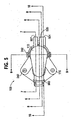
Figure 1 is a schematic flow diagram of an air assist fuel injection system according to one embodiment of the present invention. -
Figure 2 is a front perspective view of an assembly of the air assist fuel injection system illustrated inFigure 1 and in accordance with one embodiment of the present invention. -
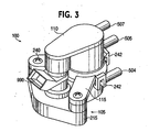
Figure 3 is a rear perspective view of the assembly illustrated inFigure 2 . -
Figure 4 is an exploded view of the assembly illustrated inFigure 2 . -
Figure 5 is a top view of the assembly illustrated inFigure 2 . -
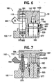
Figure 6 is a cross-sectional view of the assembly illustrated inFigure 2 taken along the line 6-6 inFigure 5 . -
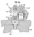
Figure 6A is a cross-sectional view of the assembly illustrated inFigure 2 taken along the line 6-6 inFigure 5 , where the assembly is mounted to the head of an engine having an air assist fuel injector therein. -
Figure 7 is a cross-sectional view of the assembly illustrated inFigure 2 taken along the line 7-7 inFigure 5 . -
Figure 8 is a cross-sectional view of the assembly illustrated inFigure 2 taken along the line 8-8 inFigure 5 . -
Figure 9 is a cross-sectional view of the assembly illustrated inFigure 2 taken along the line 9-9 inFigure 5 . -
Figure 10 is a cross-sectional view of the assembly illustrated inFigure 2 taken along the line 10-10 inFigure 5 . -
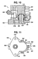
Figure 11 is a bottom view of the assembly illustrated inFigure 2 . -
Figure 12 is a top view of the rail of the assembly illustrated inFigure 2 . -
Figure 13 is a bottom view of the cover of the assembly illustrated inFigure 2 . -
Figure 14 is a cross-sectional view of the pressure regulator of the assembly illustrated inFigure 2 taken along the line 6-6 inFigure 5 . -
Figure 1 illustrates a flow diagram of an air assistfuel injection system 50 in accordance with one embodiment of the present invention. The illustrated embodiment of the air assistfuel injection system 50 is configured for a two-stroke engine and includes onefuel injector 990 and one airassist fuel injector 911. Alternative embodiments of the air assistfuel injection system 50 may includemore injectors Figure 1 . For example, in an alternative embodiment, thesystem 50 includes four airassist fuel injectors 911 and fourfuel injectors 990. - The operation of the air assist
fuel injection system 50 is first briefly described, followed by description of anassembly 100 of the air assist fuel injection system. During operation of the air assistfuel injection system 50, pressurized gas from acompressor 914 is supplied to arail 105 via agas line 916. Therail 105 then fluidly communicates the pressurized gas to the air assistfuel injector 911 and to afuel pressure regulator 900. In the illustrated embodiment, agas pressure regulator 920 is included in the gas supply flow path g and maintains the gas supply pressure at an essentially constant level during operation of thesystem 50. Agas pressure sensor 933 and adamping volume 921 are also included in the illustrated gas supply flow path g. - Liquid fuel is also supplied to a
cover 110 from afuel tank 980 via afuel line 907 by apump 982. Thecover 110 then fluidly communicates the fuel to thefuel injector 990 and thefuel pressure regulator 900. As is illustrated inFigure 1 , thefuel pressure regulator 900 is in the fuel supply flow path f between thefuel tank 980 and thefuel injector 990, as well as in the gas supply flow path g between thecompressor 914 and the airassist fuel injector 911. Thefuel pressure regulator 900 maintains the fuel supply pressure at a generally constant level during operation of the air assistfuel injection system 50 to ensure proper fuel flow characteristics to and through theinjectors fuel pressure regulator 900 maintains this fuel supply pressure at a constant level by maintaining a pressure differential between the fuel supply pressure and a reference pressure. Because the gas supply pressure is generally constant in the illustrated embodiment, it serves as a reference pressure by which thefuel pressure regulator 900 sets the fuel supply pressure for theinjectors fuel pressure regulator 900, fuel is returned from the fuel pressure regulator to thecover 110, which in turn fluidly communicates the returned fuel to thefuel tank 980 via afuel return line 915. - During operation of the air assist
fuel injection system 50, thefuel injector 990 receives the fuel from thecover 110 and then delivers a metered quantity of fuel to the airassist fuel injector 911. The airassist fuel injector 911 atomizes the fuel supplied from thefuel injector 990 with the pressurized gas supplied from therail 105, and conveys the atomized mixture to acombustion chamber 1002 of an engine 1000 (seeFigure 6a ). - To increase or decrease the speed of the
engine 1000, athrottle 902 is adjusted by an operator or computer. In response to this operation, an electronic control unit ("ECU") 918 sends a signal to thefuel injector 990 and/or the airassist fuel injector 911 which decreases or increases the mass flow rate of fuel from the airassist fuel injector 911 to correspondingly increase or decrease the speed of the engine. For example, to increase the volume of fuel delivered by the airassist fuel injector 911 in response to a throttle change, the ECU 918 may: (1) instruct a solenoid of thefuel injector 990 to stay open longer; (2) instruct a solenoid of the airassist fuel injector 911 to stay open longer; and/or (3) change the delay between the respective openings of theinjectors injectors fuel pressure regulator 900 maintains the fuel supply pressure at a constant level. - The air assist
fuel injection system 50 and the airassist fuel injector 911 are termed "air assist" because each preferably utilizes pressurized air to atomize liquid fuel. The pressure of the liquid fuel is preferably higher than that of the air. Although it is preferred that the air assistfuel injector 911 atomize liquid gasoline with pressurized air delivered by therail 105, it will be realized that the air assistfuel injector 911 may atomize many other liquid combustible forms of energy with any variety of gases. For example, the air assistfuel injector 911 may atomize liquid kerosene or liquid methane with pressurized gaseous oxygen, propane, or exhaust gas. Hence, the terms "air assist fuel injector" and "air assist fuel injection system" are terms of art, and as used herein are not intended to dictate that the air assistfuel injection system 50 or the airassist fuel injector 911 be used only with pressurized air. -
Figures 2-14 illustrate features of one embodiment of anassembly 100 of the air assistfuel injection system 50 in accordance with the present invention. Theassembly 100 is essentially one or more bodies configured to fluidly communicate pressurized gas and/or fuel to thefuel injector 990, the air assistfuel injector 911, and/or thefuel pressure regulator 900. In one embodiment, theassembly 100 includes therail 105, thecover 110, thefuel injector 990, and thefuel pressure regulator 900, which when assembled are readily mountable as a unit to theengine 1000 having the air assistfuel injector 911 mounted therein. Alternative embodiments of theassembly 100 may include more or fewer of the components of the air assistfuel injection system 50. For example, an alternative embodiment of anassembly 50 in accordance with the present invention also includes thegas pressure regulator 920 and thegas pressure sensor 933. In a further embodiment of the present invention, theassembly 100 only includes therail 105, thefuel pressure regulator 900, and the air assistfuel injector 911. In a further embodiment of the present invention, theassembly 100 only includes thecover 110 and therail 105. - As illustrated in
Figures 4 and6 , theassembly 100 includes thefuel pressure regulator 900, one embodiment of which is illustrated inFigure 14 . Thefuel pressure regulator 900 is configured to maintain the fuel supply pressure at a generally constant level to ensure proper fuel flow characteristics to and through theinjectors pressure regulator 900 includes agas reference chamber 912 defined by agas reference housing 917, and afuel chamber 922 defined by afuel housing 919. Thegas reference chamber 912 includes agas reference inlet 910 that receives the pressurized gas communicated by therail 105. Thefuel chamber 922 includesfuel inlets 927 that receive fuel communicated by thecover 110. The fuel enters thefuel chamber 922 via theinlets 927 and, under certain conditions described below, exits thepressure regulator 900 through afuel outlet 1562 of aconduit 1561. As is illustrated inFigures 14 , a flexible,impermeable diaphragm 1550 is located between thegas reference chamber 912 and thefuel chamber 922. Astopper 1520 is attached to thediaphragm 1550 directly adjacent theinlet 1560 of theconduit 1561, and aspring 1570 is located between thegas reference housing 917 and thediaphragm 1550. - When the force on the fuel side of the diaphragm 1550 (due to the fuel pressure in the fuel chamber 922) is less than the force on the gas side of the diaphragm (due to the gas pressure and the force of the spring), the
stopper 1520 will be biased toward theinlet 1560 of theconduit 1561 such that it seals the inlet of theconduit 1561 and fuel does not flow out of thepressure regulator outlet 1562. When thestopper 1520 is in this position, thepressure regulator 900 is "closed". - When the
pressure regulator 900 is closed, thepump 982 will gradually increase the fuel pressure until the force on the fuel side of the diaphragm 1550 (due to the pressure of the fuel in the fuel chamber 922) is greater than the force on the gas side of the diaphragm (due to the gas pressure in thegas reference chamber 912 and the force of the spring 1570). When this occurs, thediaphragm 1550 and the attachedstopper 1520 will move away from theinlet 1560 of theconduit 1561 such that the fuel flows through theconduit 1561 and out theoutlet 1562 of thefuel pressure regulator 900 as indicated inFigure 14 by the fuel flow path f. As is illustrated inFigure 14 , when thestopper 1520 is not abutting theinlet 1560, thefuel pressure regulator 900 is "open" and fuel flows through the fuel pressure regulator. - When the
pressure regulator 900 is open, the fuel returns to thefuel tank 980 through thefuel return line 915. This decreases the head or pressure of the fuel supply to theinjectors diaphragm 1550 is less than the force on the gas side of thediaphragm 1550 such that thefuel pressure regulator 990 is closed. This opening and closing of thefuel pressure regulator 900 will repeatedly occur as the fuel supply pressure slightly rises and falls during operation of thesystem 50. As will be appreciated, thefuel pressure regulator 900 maintains a pressure differential between the gas supply pressure and the fuel supply pressure, where the pressure differential is proportional to the biasing force of thespring 1570. Because the gas supply pressure is generally constant during operation of thesystem 50, thepressure regulator 900 thus maintains the fuel supply pressure at a substantislly constant level, which ensures proper fuel flow charactéristics through theinjectors - In alternative embodiments of the
assembly 100, thefuel pressure regulator 900 takes other configurations. For example, thefuel pressure regulator 900 may control the fuel supply pressure based on the gas supply pressure with an electronic valvo and pressure sensor. Exemplaryfuel pressure regulator 900 are also described inU.S. Patent Nos. 5,381,816 and4,934,329 . - As described above, the
fuel pressure regulator 900 controls the fuel supply pressure by utilizing fuel and pressurized gas. One feature of thepreferred assembly 100 is that it is configured to deliver pressurized gas and fuel to thefuel pressure regulator 900 such that the fuel pressure regulator can maintain the pressure differential between the pressurized fuel supply and the pressurized gas supply. In the preferred embodiment of theassembly 100, thecover 110 of theassembly 100 fluidly communicates the liquid fuel to thefuel pressure regulator 900, and therail 105 of theassembly 100 fluidly communicates the pressurized gas to the fuel pressure regulator. - The
rail 105 is a body that is configured to mount directly against, adjacent to, or generally near thehead 1002 of the engine 1000 (SeeFigure 6a ). As is illustrated inFigures 2-12 , therail 105 includes acavity 977 that receives at least a portion of thefuel pressure regulator 900. Thecavity 977 is a recess, indentation, bore, or other area capable of receiving a portion of thefuel pressure regulator 900, preferably at least a portion of thegas reference housing 917 having thegas reference inlet 910. As is illustrated inFigure 10 , therail 105 includes aninternal conduit 155, which is a channel, duct, tunnel, or other passageway inside the periphery of the rail that fluidly communicates pressurized gas from agas inlet 504 of the rail to thecavity 977. In the preferred embodiment, theconduit 155 is a cylindrical and elongated bore within the body of therail 105. Hence, the pressurized gas enters thegas inlet 504 of therail 105 from thegas line 916, and theinternal conduit 155 communicates the pressurized gas to thecavity 977 that receives thefuel pressure regulator 900. Because thegas reference inlet 910 of thefuel pressure regulator 900 is located within thecavity 977, pressurized gas communicated to the cavity by theconduit 155 will enter thegas reference chamber 912 of the fuel pressure regulator for use by thefuel pressure regulator 900 as described above. In an alternative embodiment, therail 105 includes a plurality ofseparate conduits 155 that fluidly communicate pressurized gas to thefuel pressure regulator 900. - The fuel is supplied to the
fuel pressure regulator 900 by thecover 110, which is essentially a lid, top, cap, overlay, or other body configured to cover at least a portion of thefuel pressure regulator 900 and to fluidly communicate pressurized fuel to thefuel pressure regulator 900. Hence, as is illustrated inFigures 6-10 and13 , thecover 110 also includes acavity 160 that receives at least a portion of thefuel pressure regulator 900, preferably the portion of thefuel housing 919 having thefuel inlets 927. As is illustrated inFigure 7 , thecover 110 includesinternal conduits fuel inlet 507 of the cover to thecavity 160. Hence, the fuel enters thefuel inlet 507 of thecover 110 from thefuel line 907, and theinternal conduits cavity 160 that receives thefuel pressure regulator 900. Because thefuel inlets 927 of thefuel pressure regulator 900 are located within thecavity 160, fuel communicated to the cavity by theconduits 161 will enter thefuel chamber 922 of the fuel pressure regulator for use by the fuel pressure regulator as described above. In the illustrated embodiment, thecover 110 includes threeinternal conduits fuel pressure regulator 900. However, in alternative embodiments, thecover 110 includes more or fewer of theconduits 161. For example, in one embodiment, thecover 110 includes only oneconduit 161 that fluidly communicates fuel to the fuel pressure regulator. In another embodiment, thecover 110 includes fourconduits 161 that each fluidly communicate fuel to thefuel pressure regulator 900. - As described above, fuel will exit the
fuel pressure regulator 900 through afuel outlet 1562. In the preferred embodiment, thecover 110 is further configured to fluidly communicate pressurized fuel from thefuel outlet 1562 of thefuel pressure regulator 900. Hence, as is illustrated inFigures 6 ,8-10 , and13 , thecover 110 also includes acavity 162 that receives at least a portion of thefuel pressure regulator 900, preferably the portion of thefuel housing 919 having theoutlet 1562. As is illustrated inFigure 8 , thecover 110 includes anotherinternal conduit 163 inside the periphery of the cover and that fluidly communicates fuel from thecavity 162 to afuel outlet 505 of thecover 110. Hence, the fuel exiting theoutlet 1562 of thefuel pressure regulator 900 enters thecavity 162, where it is then communicated by theconduit 163 to thefuel outlet 505 of thecover 110, which in turn communicates the fuel to thefuel return line 915 for eventual delivery to thefuel tank 980. As is apparent fromFigures 7 and14 , the cavities 160,162 are preferably cylindrical bores extending into the body of thecover 110, where the diameter of thecavity 162 is less than that of thecavity 160. - As is also apparent from
Figures 6-9 and13 , thecover 110 also fluidly communicates fuel to thefuel injector 990 and preferably covers at least a portion of the fuel injector. Hence, thecover 110 includes afurther cavity 164 that receives at least a portion of thefuel injector 990, preferably the portion of thefuel injector 990 having aninlet 991 that receives the fuel. As is illustrated inFigure 7 , theinternal conduit 161 of thecover 110 extends from theinlet 507 of thecover 110 to thecavity 164 such that theinternal conduit 161 fluidly communicates fuel from the inlet to thecavity 164. Hence, fuel enters thefuel inlet 507 of thecover 110 from thefuel line 907, and theinternal conduit 161 communicates the fuel to thecavity 164 that receives theinlet 991 of thefuel injector 990. Because theinlet 991 of thefuel injector 990 is located within thecavity 164, fuel communicated to thecavity 164 by theconduit 161 will enter thefuel injector 990, which will inject a metered quantity of the fuel in the conventional manner. In the illustrated embodiment, thefuel injector 990 is a top-feed type fuel injector, such as the Deka IV Standard injector, commercially available from SIEMENS. - As is apparent from
Figure 4 , one characteristic of the illustrated top-feedtype fuel injector 990 is that theinlet 991 and anoutlet 993 of thefuel injector 990 are coaxial with respect to the longitudinal axis of the fuel injector. In alternative embodiments, thecover 110 is configured to fluidly communicate fuel to differently configured fuel injectors, such as side-feed type fuel injectors and bottom-feed type fuel injectors. Although theconduit 161 fluidly communicates fuel to both thefuel pressure regulator 900 and thefuel injector 990, it will be appreciated that thecover 110 may be configured to fluidly communicate fuel to thefuel pressure regulator 900 and thefuel injector 990 in alternative manners. For example, in accordance with one embodiment of the present invention, thecover 110 includes a first conduit that communicates fuel solely to thefuel injector 990 and a second conduit that communicates fuel solely to thefuel pressure regulator 900, where both the first and the second conduits receive fuel from one ormore fuel inlets 507. - As described above, the
fuel injector 990 will deliver metered quantities of fuel to the air assistfuel injector 911, which will atomize the fuel with the pressurized gas. As is illustrated byFigures 4 and6-10 , therail 105 of theassembly 100 is configured to communicate the pressurized gas to the air assistfuel injector 911. Hence, therail 105 includes apassageway 979 that receives at least a portion of the air assistfuel injector 911 and at least a portion of thefuel injector 990. Thepassageway 979 is a channel, corridor, opening, duct, or other area configured to receive a portion of thefuel injector 990 and the air assistfuel injector 991. In the preferred embodiment, thepassageway 979 is a cylindrical bore passing completely through the body of therail 105 and that receives at least an inlet 972 of the air assistfuel injector 911 and at least theoutlet 993 of thefuel injector 990. - As is illustrated in
Figure 10 , besides fluidly communicating pressurized gas to thefuel pressure regulator 900, theinternal conduit 155 of therail 105 also fluidly communicates pressurized gas from thegas inlet 504 of therail 105 to thepassageway 979. Hence, pressurized gas enters thegas inlet 504 of therail 105 from thegas line 916, and theinternal conduit 155 fluidly communicates the pressurized gas to thepassageway 979 that receives the inlet 972 of the air assistfuel injector 911 and theoutlet 993 of thefuel injector 990. - As is illustrated in
Figure 6A , anannular area 970 is located between theoutlet 993 of thefuel injector 990 and the inlet 972 of the air assistfuel injector 990. In the preferred embodiment, theconduit 155 is located such that it opens into thepassageway 979 at a location adjacent thearea 970 such that pressurized gas communicated to thepassageway 979 by theconduit 155 will enter thearea 970. Because the inlet 972 of the air assistfuel injector 911 is located in thearea 970 of thepassageway 979 pressurized gas communicated to the passageway will enter the air assist fuel injector. Because theoutlet 993 of thefuel injector 990 is directly adjacent the inlet 972 of the air assistfuel injector 911, fuel is injected from the fuel injector into the air assist fuel injector. - The air assist
fuel injector 911 atomizes the fuel supplied from thefuel injector 990 with the pressurized gas communicated by therail 105, and conveys the atomized mixture to thecombustion chamber 1002 of theengine 1000. Exemplary configurations of the air assistfuel injector 911 are described inU.S. Patent Nos. 6,302,337 and4,934,329 , the entire disclosures of which are hereby incorporated by reference. In an alternative embodiment of theassembly 100, therail 105 includes more than oneinternal conduit 155 that fluidly communicates pressurized gas to thefuel pressure regulator 900 and/or to the air assistfuel injector 911. - In the illustrated embodiment, a number of seals are defined between the
fuel pressure regulator 900 and thecover 110. As is illustrated inFigure 6 , theassembly 100 includes afirst seal member 223, which defines a seal between thecover 110 and thefuel pressure regulator 900 that prevents liquid fuel from leaking from thecavity 160 to the exterior environment. Theseal member 223 abuts thefuel housing 917 and an interior surface of thecavity 160 to define the seal. - The
assembly 100 also includes asecond seal member 225, which defines a seal between thefuel pressure regulator 900 and thecover 110 that prevents liquid fuel in thecavity 160 from leaking into thecavity 162 and vice versa. Theseal member 225 abuts thefuel housing 917 adjacent the fuel outlet 1652 as well as the interior surface of thecavity 162. - As is also illustrated in
Figure 6 , theassembly 100 includes athird seal member 220 and aretainer 230. Theseal member 220 abuts theretainer 230, the interior surface of thecavity 977 and thegas housing 917 to define a seal that prevents pressurized gas in thecavity 997 from leaking to the exterior environment. - Additionally, a number of seals are defined between the
fuel injector 990 and thecover 110, between the fuel injector and therail 105, and between the air assistfuel injector 911 and therail 105. Hence, as best seen inFigure 6A , the assembly includes afourth seal member 995 and afifth seal member 997. Theseal member 995 defines a seal between thefuel injector 990 and the interior surface of thecavity 164 to prevent liquid fuel from leaking from the cavity to the exterior environment. Theseal member 997 defines a seal between thefuel injector 990 and the interior surface of thepassageway 979 to prevent liquid fuel and pressurized gas from leaking to the exterior environment. As is illustrated inFigure 6A , the air assistfuel injector 911 also includes aseal member 913 that defines a seal between the air assist fuel injector and the interior surface of thepassageway 979 so as to prevent liquid fuel and gas from leaking to the exterior environment. Theseals - To assemble the
assembly 100, thefuel injector 990 is located in thefuel injector cavity 979 of therail 105. Theretainer 230 andseal member 220 are placed over thegas reference housing 917 of thefuel pressure regulator 900. Thefuel pressure regulator 900 is then placed in thecavity 977 of therail 105. Theseal members fuel pressure regulator 900. Thecover 110 is then attached to therail 105 such that thefuel pressure regulator 900 and thefuel injector 990 are covered by thecover 110 and retained in therail 105. In the preferred embodiment thecover 110 is attached to therail 105 withclips 242, which are devices that grip or hold the cover to the rail. In alternative embodiments of theassembly 100, thecover 110 is attached to therail 105 with other attachment devices, such as a threaded fastener clamp, weld, glue, or other device. - After the
assembly 100 is assembled, therail 105 is located adjacent the head of the engine 1000 (having the air assistfuel injector 911 mounted therein) such that thepassageway 979 receives the inlet 972 of the air assistfuel injector 911. In the preferred embodiment,fasteners 240 are then passed through mountingflanges cover 110 and therail 105 to attach theassembly 100 to the head of theengine 1000. Thefasteners 240 thread into theengine 1000 and further bias thecover 110 toward the rail. In alternative embodiments, theassembly 100 is attached to theengine 1000 in other manners. For example, in one embodiment, therail 105 is attached to the head with fasteners or other devices and thecover 110 is separately attached to the rail. It will be appreciated that the order of the above-noted assembly steps may vary. For example, thefuel injector 990 may be located in therail 105 after thepressure regulator 900, and therail 105 may be located on the head before thecover 110 is attached to the rail with clips 202. - Besides communicating pressurized fuel to the
fuel pressure regulator 900 and thefuel injector 990, the preferred embodiment of thecover 110 also retains thepressure regulator 900 and thefuel injector 990 within therail 105. That is, thecover 110 biases thepressure regulator 900 against therail 105 so as to maintain thepressure regulator 900 in place withincavity 977 of therail 105 and biases thefuel injector 990 against the rail so as to maintain the fuel injector in place within thepassageway 979 of therail 105. When assembled, abottom face 181 of thecover 110 abuts anupper surface 932 of apressure regulator flange 931, and abottom surface 933 of thepressure regulator flange 931 abuts anupper surface 978 of therail 105. Additionally, abottom face 183 of the portion of thecover 110 adjacent thecavity 164 abuts aseat 992 of thefuel injector 990. Hence, the force attaching thecover 110 to therail 105 retains thepressure regulator 900 in therail 105. Because thepressure regulator 900 and thefuel injector 990 are not independently fixed to therail 105, each is easily installed and removed, simplifying the assembly and disassembly of theassembly 100. - In alternative embodiments, the
pressure regulator 900 is retained in therail 105 in other manners. For example, thecover 110 may bias opposing surfaces of thecover 110,pressure regulator 900,fuel injector 990, andrail 105 in the radial direction of the pressure regulator. In a further embodiment of theassembly 100 of the present invention, thecover 110 does not retain thepressure regulator 900 or thefuel injector 990 within therail 105. For example, thecover 110, the pressure regulator, and thefuel injector 990 may be independently fixed to therail 105 with separate fasteners. - While the preferred embodiment of the
cover 110 is illustrated, it will be appreciated that thecover 110 may take alternative configurations that are also effective to fluidly communicate pressurized fuel to theinlet 927 of thepressure regulator 900 and the fuel inlet 491 of thefuel injector 990. Additionally, therail 105 may take other configurations. For example, in an alternative embodiment, therail 105 does not receive thefuel injector 990 or the air assistfuel injector 911. In this alternative embodiment, thefuel injector 990 and/or the air assistfuel injector 911 are mounted to the head of theengine 1000 or another body separate from therail 105. Therail 105 may also include differently configured conduits for conveying the pressurized gas. - As will be appreciated, the
assembly 100 according to one embodiments of the present invention fluidly communicates pressurized fuel to thefuel pressure regulator 900 and thefuel injector 990. and pressurized gas to the air assistfuel injector 911 and thefuel pressure regulator 900 in a compact and easily assembled manner. Additionaly, as a unit, theassembly 100 is easily mounted and attached to theengine 1000. Hence, theassembly 100 decreases manufacturing and assembly complications and simplifies replacement or repair of the assembly components as compared to some concentrical configurations.
Claims (15)
- An assembly comprising:an air assist fuel injector (911),a fuel injector (990) for delivering fuel to the air assist fuel injector (911),a fuel pressure regulator (900), anda rail (105) having an outiet passage (979) for delivering gas and fuel to the air assist fuel injector (911), characterized in that the pressure regulator comprises a housing formed of a gas reference housing (917) and a fuel housing (919) andin that the pressure regulator (900) and the fuel injector (990) are both located at least partly in the rail (105) and partly in a cover (110), the cover being formed with a fuel passage (161) for delivering fuel to the fuel injector (990) and to the fuel housing (919), and the rail (105) having a gas passage (155, 1559) for delivering pressurized gas to the gas reference housing (197) of the fuel pressure regulator (990).
- An assembly accordingly to claim 1, wherein the fuel injector (990) is a top-feed fuel injector.
- An assembly according to claim 1 or 2, wherein the passageway (979) receives at least an inlet of said air assist fuel injector (911).
- An assembly according to claim 3, wherein the passageway (979) also receives at least an outlet of said fuel injector (990).
- An assembly according to claim 4, wherein outlet of the fuel injector (990), the inlet of the air assist fuel injector (911), and an inlet of the fuel injector (990) are each coaxial with respect to a longitudinal axis of the fuel injector (990).
- An assembly according to claim 5, wherein the outlet of the fuel injector (990) is located so as to feed fuel to the inlet of the air assist fuel injector (911).
- An assembly according to any preceding claim, wherein the cover (110) has a cavity (160) that receives said fuel pressure regulator (900).
- An assembly according to any preceding claim, wherein the cover has a cavity (164) that receives said fuel injector (990).
- An assembly according to any preceding claim, wherein the cover includes a fuel inlet (507) and a fuel outlet (1619).
- An assembly according to any preceding claim, wherein the cover (110) is attached to the rail (105).
- An assembly according to claim 10, wherein the cover (110) is attached to the rail (105) with at least one clip (242).
- An assembly according to any preceding claim, wherein the cover (110) and the rail are attached to an engine head (1000).
- An assembly according to any preceding claim, wherein the said rail (105) has a cavity (977) that receives said gas reference housing (917).
- An assembly according to any preceding claim, wherein the fuel pressure regulator includes a diaphram (1550) located between said gas reference housing (917) and said fuel housing (919).
- An assembly according to any preceding claim wherein rail (105) has a cavity (977) that receives said fuel pressure regulator (900) that receives said air assist fuel injector (911), said gas passage (155) of said rail being in fluid communication with said cavity and said passageway.
Applications Claiming Priority (3)
| Application Number | Priority Date | Filing Date | Title |
|---|---|---|---|
| US13369 | 2001-12-13 | ||
| US10/013,369 US6626161B2 (en) | 2001-12-13 | 2001-12-13 | Methods and assemblies for delivering fuel and gas in air assist fuel injection systems |
| PCT/US2002/033698 WO2003052263A1 (en) | 2001-12-13 | 2002-10-23 | Methods and assemblies for delivering fuel and gas in air assist fuel injection systems |
Publications (2)
| Publication Number | Publication Date |
|---|---|
| EP1456532A1 EP1456532A1 (en) | 2004-09-15 |
| EP1456532B1 true EP1456532B1 (en) | 2008-08-20 |
Family
ID=21759611
Family Applications (1)
| Application Number | Title | Priority Date | Filing Date |
|---|---|---|---|
| EP02784210A Expired - Lifetime EP1456532B1 (en) | 2001-12-13 | 2002-10-23 | Assembly for delivering fuel and gas in air assist fuel injection systems |
Country Status (7)
| Country | Link |
|---|---|
| US (1) | US6626161B2 (en) |
| EP (1) | EP1456532B1 (en) |
| JP (1) | JP2005513325A (en) |
| AT (1) | ATE405741T1 (en) |
| AU (1) | AU2002347998A1 (en) |
| DE (1) | DE60228488D1 (en) |
| WO (1) | WO2003052263A1 (en) |
Families Citing this family (3)
| Publication number | Priority date | Publication date | Assignee | Title |
|---|---|---|---|---|
| JP4119864B2 (en) * | 2004-03-31 | 2008-07-16 | 三菱重工業株式会社 | Fuel injection device for internal combustion engine |
| US20130199494A1 (en) * | 2012-02-06 | 2013-08-08 | Vianney Rabhi | High-pressure spark-ignition and stratification device for an internal combustion engine |
| CN111212967B (en) * | 2017-09-14 | 2022-09-30 | 奥比托澳大利亚有限公司 | Control strategy for engine operation |
Family Cites Families (33)
| Publication number | Priority date | Publication date | Assignee | Title |
|---|---|---|---|---|
| US3241805A (en) | 1962-10-23 | 1966-03-22 | Powers Regulator Co | Valve |
| US3789819A (en) | 1972-01-28 | 1974-02-05 | Gen Motors Corp | Fuel rail vapor bleed |
| DE2702133A1 (en) | 1977-01-20 | 1978-07-27 | Bosch Gmbh Robert | STORAGE |
| US4475486A (en) | 1982-02-18 | 1984-10-09 | General Motors Corporation | Engine induction system |
| DE3374328D1 (en) | 1983-07-06 | 1987-12-10 | Gen Motors Corp | Fuel injection apparatus |
| US4693223A (en) | 1984-06-21 | 1987-09-15 | General Motors Corporation | Fuel injection valve connection |
| CA1275210C (en) | 1984-07-25 | 1990-10-16 | John William Koch | Air supply system for fuel injection system |
| IN165341B (en) | 1984-08-01 | 1989-09-23 | Orbital Eng Pty | |
| US4756289A (en) | 1986-02-12 | 1988-07-12 | General Motors Corporation | Self-contained fuel pressure regulator |
| US4840163A (en) * | 1987-01-08 | 1989-06-20 | Colt Industries Inc. | Electromagnet, valve assembly and fuel metering apparatus |
| MX169738B (en) | 1987-04-03 | 1993-07-22 | Orbital Eng Pty | FUEL INJECTION SYSTEM FOR AN INTERNAL COMBUSTION ENGINE OF MULTIPLE CYLINDERS |
| US5094211A (en) | 1988-09-28 | 1992-03-10 | Siemens Automotive L.P. | Automotive fuel rail assemblies with integral means for mounting fuel regulator |
| US4991556A (en) | 1988-09-28 | 1991-02-12 | Siemens-Bendix Automotive Electronics L.P. | Automotive fuel rail assemblies with integral means for mounting fuel regulator |
| US5207205A (en) | 1988-12-07 | 1993-05-04 | Siemens Automotive L.P. | Fuel injection device with air-assisted fuel diffusion |
| JP2790676B2 (en) | 1989-10-02 | 1998-08-27 | ヤマハ発動機株式会社 | Air fuel injection type two-stroke engine |
| US5261375A (en) | 1989-11-06 | 1993-11-16 | General Motors Corporation | Fuel injection assembly for integrated induction system |
| JP2761422B2 (en) * | 1990-01-10 | 1998-06-04 | 三信工業株式会社 | Fuel injection engine |
| US5070844A (en) | 1990-07-23 | 1991-12-10 | Siemens Automotive L.P. | Composite fuel rail socket for bottom- and side-feed fuel injectors |
| US5101800A (en) | 1990-12-07 | 1992-04-07 | General Motors Corporation | Fuel injection |
| JP2725468B2 (en) * | 1991-03-27 | 1998-03-11 | トヨタ自動車株式会社 | Fuel injection device for internal combustion engine |
| US5170766A (en) | 1992-01-16 | 1992-12-15 | Orbital Walbro Corporation | Fuel and air injection for multi-cylinder internal combustion engines |
| US5320078A (en) | 1992-03-11 | 1994-06-14 | Siemens Automotive L.P. | Remote mounting of a fuel pressure regulator for an engine |
| US5279327A (en) | 1992-08-31 | 1994-01-18 | Orbital Walbro Corporation | Pressure regulator |
| US5291822A (en) | 1992-11-16 | 1994-03-08 | Orbital Walbro Corporation | Diaphragm for pressure regulators and method of making |
| US5315968A (en) | 1993-03-29 | 1994-05-31 | Orbital Walbro Corporation | Two-stage fuel delivery system for an internal combustion engine |
| DE4332118A1 (en) | 1993-09-22 | 1995-03-23 | Bosch Gmbh Robert | Fuel injection device |
| AUPM656594A0 (en) | 1994-06-30 | 1994-07-21 | Orbital Engine Company (Australia) Proprietary Limited | A method and apparatus relating to control of the operation of an internal combustion engine |
| US5463997A (en) | 1994-10-05 | 1995-11-07 | Cutler Induction Systems, Inc. | Single point fuel injection system |
| US5577478A (en) | 1995-11-03 | 1996-11-26 | Walbro Corporation | Integrated fuel pressure regulator and rail assembly |
| US5666927A (en) | 1996-07-26 | 1997-09-16 | Siemens Automotive Corporation | Fuel/air supply system for a fuel injector and methods of operation |
| US6053149A (en) | 1998-05-28 | 2000-04-25 | Siemens Automotive Corporation | Fuel injector clip retention arrangement |
| US6161527A (en) * | 1999-02-11 | 2000-12-19 | Brunswick Corporation | Air assisted direct fuel injection system |
| US6302337B1 (en) | 2000-08-24 | 2001-10-16 | Synerject, Llc | Sealing arrangement for air assist fuel injectors |
-
2001
- 2001-12-13 US US10/013,369 patent/US6626161B2/en not_active Expired - Lifetime
-
2002
- 2002-10-23 WO PCT/US2002/033698 patent/WO2003052263A1/en active Application Filing
- 2002-10-23 AT AT02784210T patent/ATE405741T1/en not_active IP Right Cessation
- 2002-10-23 EP EP02784210A patent/EP1456532B1/en not_active Expired - Lifetime
- 2002-10-23 DE DE60228488T patent/DE60228488D1/en not_active Expired - Fee Related
- 2002-10-23 JP JP2003553122A patent/JP2005513325A/en active Pending
- 2002-10-23 AU AU2002347998A patent/AU2002347998A1/en not_active Abandoned
Also Published As
| Publication number | Publication date |
|---|---|
| WO2003052263A1 (en) | 2003-06-26 |
| DE60228488D1 (en) | 2008-10-02 |
| US6626161B2 (en) | 2003-09-30 |
| EP1456532A1 (en) | 2004-09-15 |
| JP2005513325A (en) | 2005-05-12 |
| ATE405741T1 (en) | 2008-09-15 |
| US20030111064A1 (en) | 2003-06-19 |
| AU2002347998A1 (en) | 2003-06-30 |
Similar Documents
| Publication | Publication Date | Title |
|---|---|---|
| US6135092A (en) | Fuel injection system | |
| US7481381B2 (en) | Fuel injector having an external cross-flow nozzle for enhanced compressed natural gas jet spray | |
| KR100448295B1 (en) | Gas fuel injection method and apparatus for internal combustion engine | |
| US6041594A (en) | Mixture delivery device for internal combustion engines | |
| JP2680176B2 (en) | Method and apparatus for controlling fluid flow rate | |
| JPH08151968A (en) | Fuel injection device for internal combustion engine | |
| US20080006713A1 (en) | Fuel injector having an internally mounted cross-flow nozzle for enhanced compressed natural gas jet spray | |
| EP1039123B1 (en) | Fuel recirculation for direct injection fuel system using a high pressure variable venturi pump | |
| US4463740A (en) | Device for controlling atomization of fuel in internal combustion engine | |
| EP1456532B1 (en) | Assembly for delivering fuel and gas in air assist fuel injection systems | |
| US6502561B2 (en) | Cover for a fuel pressure regulator of an air assist fuel injection system | |
| US6145495A (en) | Propane injection system for a diesel engine | |
| US5447140A (en) | Fuel injection | |
| EP0934460B1 (en) | Air assist fuel injector | |
| US5463997A (en) | Single point fuel injection system | |
| EP1045984B1 (en) | Fuel injection system | |
| US7172178B1 (en) | Carburetor with acceleration fuel pump | |
| NL8600611A (en) | LPG driven IC-engine - has pressure regulator in gas supply line, with incorporated valve and filter | |
| US5320081A (en) | Fuel injection economizer | |
| JP2005513325A5 (en) | ||
| SU1164450A1 (en) | Fuel supply system for internal combustion engine | |
| KR20000026607A (en) | Adaptor for injector spraying two fluids | |
| JPH03246364A (en) | Injection nozzle and its injection pressure control device | |
| JPH02163463A (en) | Fuel injection valve |
Legal Events
| Date | Code | Title | Description |
|---|---|---|---|
| PUAI | Public reference made under article 153(3) epc to a published international application that has entered the european phase |
Free format text: ORIGINAL CODE: 0009012 |
|
| 17P | Request for examination filed |
Effective date: 20040707 |
|
| AK | Designated contracting states |
Kind code of ref document: A1 Designated state(s): AT BE BG CH CY CZ DE DK EE ES FI FR GB GR IE IT LI LU MC NL PT SE SK TR |
|
| AX | Request for extension of the european patent |
Extension state: AL LT LV MK RO SI |
|
| 17Q | First examination report despatched |
Effective date: 20070613 |
|
| GRAP | Despatch of communication of intention to grant a patent |
Free format text: ORIGINAL CODE: EPIDOSNIGR1 |
|
| RTI1 | Title (correction) |
Free format text: ASSEMBLY FOR DELIVERING FUEL AND GAS IN AIR ASSIST FUEL INJECTION SYSTEMS |
|
| GRAS | Grant fee paid |
Free format text: ORIGINAL CODE: EPIDOSNIGR3 |
|
| GRAA | (expected) grant |
Free format text: ORIGINAL CODE: 0009210 |
|
| AK | Designated contracting states |
Kind code of ref document: B1 Designated state(s): AT BE BG CH CY CZ DE DK EE ES FI FR GB GR IE IT LI LU MC NL PT SE SK TR |
|
| REG | Reference to a national code |
Ref country code: GB Ref legal event code: FG4D |
|
| REG | Reference to a national code |
Ref country code: CH Ref legal event code: EP |
|
| REG | Reference to a national code |
Ref country code: IE Ref legal event code: FG4D |
|
| REF | Corresponds to: |
Ref document number: 60228488 Country of ref document: DE Date of ref document: 20081002 Kind code of ref document: P |
|
| PG25 | Lapsed in a contracting state [announced via postgrant information from national office to epo] |
Ref country code: NL Free format text: LAPSE BECAUSE OF FAILURE TO SUBMIT A TRANSLATION OF THE DESCRIPTION OR TO PAY THE FEE WITHIN THE PRESCRIBED TIME-LIMIT Effective date: 20080820 Ref country code: ES Free format text: LAPSE BECAUSE OF FAILURE TO SUBMIT A TRANSLATION OF THE DESCRIPTION OR TO PAY THE FEE WITHIN THE PRESCRIBED TIME-LIMIT Effective date: 20081201 |
|
| PG25 | Lapsed in a contracting state [announced via postgrant information from national office to epo] |
Ref country code: FI Free format text: LAPSE BECAUSE OF FAILURE TO SUBMIT A TRANSLATION OF THE DESCRIPTION OR TO PAY THE FEE WITHIN THE PRESCRIBED TIME-LIMIT Effective date: 20080820 |
|
| PG25 | Lapsed in a contracting state [announced via postgrant information from national office to epo] |
Ref country code: BE Free format text: LAPSE BECAUSE OF FAILURE TO SUBMIT A TRANSLATION OF THE DESCRIPTION OR TO PAY THE FEE WITHIN THE PRESCRIBED TIME-LIMIT Effective date: 20080820 |
|
| PG25 | Lapsed in a contracting state [announced via postgrant information from national office to epo] |
Ref country code: DK Free format text: LAPSE BECAUSE OF FAILURE TO SUBMIT A TRANSLATION OF THE DESCRIPTION OR TO PAY THE FEE WITHIN THE PRESCRIBED TIME-LIMIT Effective date: 20080820 Ref country code: BG Free format text: LAPSE BECAUSE OF FAILURE TO SUBMIT A TRANSLATION OF THE DESCRIPTION OR TO PAY THE FEE WITHIN THE PRESCRIBED TIME-LIMIT Effective date: 20081120 |
|
| PG25 | Lapsed in a contracting state [announced via postgrant information from national office to epo] |
Ref country code: SK Free format text: LAPSE BECAUSE OF FAILURE TO SUBMIT A TRANSLATION OF THE DESCRIPTION OR TO PAY THE FEE WITHIN THE PRESCRIBED TIME-LIMIT Effective date: 20080820 Ref country code: PT Free format text: LAPSE BECAUSE OF FAILURE TO SUBMIT A TRANSLATION OF THE DESCRIPTION OR TO PAY THE FEE WITHIN THE PRESCRIBED TIME-LIMIT Effective date: 20090120 Ref country code: CZ Free format text: LAPSE BECAUSE OF FAILURE TO SUBMIT A TRANSLATION OF THE DESCRIPTION OR TO PAY THE FEE WITHIN THE PRESCRIBED TIME-LIMIT Effective date: 20080820 Ref country code: MC Free format text: LAPSE BECAUSE OF NON-PAYMENT OF DUE FEES Effective date: 20081031 |
|
| REG | Reference to a national code |
Ref country code: CH Ref legal event code: PL |
|
| PLBE | No opposition filed within time limit |
Free format text: ORIGINAL CODE: 0009261 |
|
| STAA | Information on the status of an ep patent application or granted ep patent |
Free format text: STATUS: NO OPPOSITION FILED WITHIN TIME LIMIT |
|
| REG | Reference to a national code |
Ref country code: IE Ref legal event code: MM4A |
|
| 26N | No opposition filed |
Effective date: 20090525 |
|
| GBPC | Gb: european patent ceased through non-payment of renewal fee |
Effective date: 20081120 |
|
| PG25 | Lapsed in a contracting state [announced via postgrant information from national office to epo] |
Ref country code: EE Free format text: LAPSE BECAUSE OF FAILURE TO SUBMIT A TRANSLATION OF THE DESCRIPTION OR TO PAY THE FEE WITHIN THE PRESCRIBED TIME-LIMIT Effective date: 20080820 |
|
| PG25 | Lapsed in a contracting state [announced via postgrant information from national office to epo] |
Ref country code: DE Free format text: LAPSE BECAUSE OF NON-PAYMENT OF DUE FEES Effective date: 20090501 |
|
| PG25 | Lapsed in a contracting state [announced via postgrant information from national office to epo] |
Ref country code: LI Free format text: LAPSE BECAUSE OF NON-PAYMENT OF DUE FEES Effective date: 20081031 Ref country code: IE Free format text: LAPSE BECAUSE OF NON-PAYMENT OF DUE FEES Effective date: 20081023 Ref country code: CH Free format text: LAPSE BECAUSE OF NON-PAYMENT OF DUE FEES Effective date: 20081031 |
|
| PG25 | Lapsed in a contracting state [announced via postgrant information from national office to epo] |
Ref country code: GB Free format text: LAPSE BECAUSE OF NON-PAYMENT OF DUE FEES Effective date: 20081120 |
|
| PG25 | Lapsed in a contracting state [announced via postgrant information from national office to epo] |
Ref country code: SE Free format text: LAPSE BECAUSE OF FAILURE TO SUBMIT A TRANSLATION OF THE DESCRIPTION OR TO PAY THE FEE WITHIN THE PRESCRIBED TIME-LIMIT Effective date: 20081120 |
|
| PGFP | Annual fee paid to national office [announced via postgrant information from national office to epo] |
Ref country code: AT Payment date: 20091013 Year of fee payment: 8 |
|
| PG25 | Lapsed in a contracting state [announced via postgrant information from national office to epo] |
Ref country code: CY Free format text: LAPSE BECAUSE OF FAILURE TO SUBMIT A TRANSLATION OF THE DESCRIPTION OR TO PAY THE FEE WITHIN THE PRESCRIBED TIME-LIMIT Effective date: 20080820 Ref country code: LU Free format text: LAPSE BECAUSE OF NON-PAYMENT OF DUE FEES Effective date: 20081023 |
|
| PG25 | Lapsed in a contracting state [announced via postgrant information from national office to epo] |
Ref country code: TR Free format text: LAPSE BECAUSE OF FAILURE TO SUBMIT A TRANSLATION OF THE DESCRIPTION OR TO PAY THE FEE WITHIN THE PRESCRIBED TIME-LIMIT Effective date: 20080820 |
|
| PG25 | Lapsed in a contracting state [announced via postgrant information from national office to epo] |
Ref country code: GR Free format text: LAPSE BECAUSE OF FAILURE TO SUBMIT A TRANSLATION OF THE DESCRIPTION OR TO PAY THE FEE WITHIN THE PRESCRIBED TIME-LIMIT Effective date: 20081121 |
|
| PGFP | Annual fee paid to national office [announced via postgrant information from national office to epo] |
Ref country code: IT Payment date: 20101023 Year of fee payment: 9 |
|
| PG25 | Lapsed in a contracting state [announced via postgrant information from national office to epo] |
Ref country code: AT Free format text: LAPSE BECAUSE OF NON-PAYMENT OF DUE FEES Effective date: 20101023 |
|
| PGFP | Annual fee paid to national office [announced via postgrant information from national office to epo] |
Ref country code: FR Payment date: 20111103 Year of fee payment: 10 |
|
| REG | Reference to a national code |
Ref country code: FR Ref legal event code: ST Effective date: 20130628 |
|
| PG25 | Lapsed in a contracting state [announced via postgrant information from national office to epo] |
Ref country code: IT Free format text: LAPSE BECAUSE OF NON-PAYMENT OF DUE FEES Effective date: 20121023 Ref country code: FR Free format text: LAPSE BECAUSE OF NON-PAYMENT OF DUE FEES Effective date: 20121031 |