EP1455641B1 - Method and device for monitoring analyte concentration by optical detection - Google Patents
Method and device for monitoring analyte concentration by optical detection Download PDFInfo
- Publication number
- EP1455641B1 EP1455641B1 EP02791814A EP02791814A EP1455641B1 EP 1455641 B1 EP1455641 B1 EP 1455641B1 EP 02791814 A EP02791814 A EP 02791814A EP 02791814 A EP02791814 A EP 02791814A EP 1455641 B1 EP1455641 B1 EP 1455641B1
- Authority
- EP
- European Patent Office
- Prior art keywords
- areas
- light
- compounds
- tissue
- detection means
- Prior art date
- Legal status (The legal status is an assumption and is not a legal conclusion. Google has not performed a legal analysis and makes no representation as to the accuracy of the status listed.)
- Expired - Lifetime
Links
- 238000000034 method Methods 0.000 title claims abstract description 19
- 238000001514 detection method Methods 0.000 title claims description 26
- 230000003287 optical effect Effects 0.000 title abstract description 15
- 239000012491 analyte Substances 0.000 title description 2
- 238000012544 monitoring process Methods 0.000 title description 2
- 150000001875 compounds Chemical class 0.000 claims abstract description 52
- 238000004458 analytical method Methods 0.000 claims abstract description 25
- WQZGKKKJIJFFOK-GASJEMHNSA-N Glucose Natural products OC[C@H]1OC(O)[C@H](O)[C@@H](O)[C@@H]1O WQZGKKKJIJFFOK-GASJEMHNSA-N 0.000 claims abstract description 22
- 239000008103 glucose Substances 0.000 claims abstract description 22
- 239000012528 membrane Substances 0.000 claims description 14
- 125000006850 spacer group Chemical group 0.000 claims description 12
- 239000000560 biocompatible material Substances 0.000 claims description 4
- 238000002513 implantation Methods 0.000 claims description 4
- 230000023077 detection of light stimulus Effects 0.000 claims 1
- 230000000694 effects Effects 0.000 abstract description 10
- 230000003993 interaction Effects 0.000 abstract description 10
- 239000008280 blood Substances 0.000 abstract description 9
- 210000004369 blood Anatomy 0.000 abstract description 9
- 206010012601 diabetes mellitus Diseases 0.000 abstract description 6
- 238000005259 measurement Methods 0.000 description 28
- 230000005540 biological transmission Effects 0.000 description 3
- 230000015572 biosynthetic process Effects 0.000 description 3
- 230000008859 change Effects 0.000 description 3
- 230000001965 increasing effect Effects 0.000 description 3
- 239000007788 liquid Substances 0.000 description 3
- 239000000126 substance Substances 0.000 description 3
- 238000003149 assay kit Methods 0.000 description 2
- 230000015556 catabolic process Effects 0.000 description 2
- 238000001816 cooling Methods 0.000 description 2
- 238000007405 data analysis Methods 0.000 description 2
- 238000006731 degradation reaction Methods 0.000 description 2
- 230000001419 dependent effect Effects 0.000 description 2
- 238000009792 diffusion process Methods 0.000 description 2
- 238000010438 heat treatment Methods 0.000 description 2
- NOESYZHRGYRDHS-UHFFFAOYSA-N insulin Chemical compound N1C(=O)C(NC(=O)C(CCC(N)=O)NC(=O)C(CCC(O)=O)NC(=O)C(C(C)C)NC(=O)C(NC(=O)CN)C(C)CC)CSSCC(C(NC(CO)C(=O)NC(CC(C)C)C(=O)NC(CC=2C=CC(O)=CC=2)C(=O)NC(CCC(N)=O)C(=O)NC(CC(C)C)C(=O)NC(CCC(O)=O)C(=O)NC(CC(N)=O)C(=O)NC(CC=2C=CC(O)=CC=2)C(=O)NC(CSSCC(NC(=O)C(C(C)C)NC(=O)C(CC(C)C)NC(=O)C(CC=2C=CC(O)=CC=2)NC(=O)C(CC(C)C)NC(=O)C(C)NC(=O)C(CCC(O)=O)NC(=O)C(C(C)C)NC(=O)C(CC(C)C)NC(=O)C(CC=2NC=NC=2)NC(=O)C(CO)NC(=O)CNC2=O)C(=O)NCC(=O)NC(CCC(O)=O)C(=O)NC(CCCNC(N)=N)C(=O)NCC(=O)NC(CC=3C=CC=CC=3)C(=O)NC(CC=3C=CC=CC=3)C(=O)NC(CC=3C=CC(O)=CC=3)C(=O)NC(C(C)O)C(=O)N3C(CCC3)C(=O)NC(CCCCN)C(=O)NC(C)C(O)=O)C(=O)NC(CC(N)=O)C(O)=O)=O)NC(=O)C(C(C)CC)NC(=O)C(CO)NC(=O)C(C(C)O)NC(=O)C1CSSCC2NC(=O)C(CC(C)C)NC(=O)C(NC(=O)C(CCC(N)=O)NC(=O)C(CC(N)=O)NC(=O)C(NC(=O)C(N)CC=1C=CC=CC=1)C(C)C)CC1=CN=CN1 NOESYZHRGYRDHS-UHFFFAOYSA-N 0.000 description 2
- 239000011159 matrix material Substances 0.000 description 2
- 230000004044 response Effects 0.000 description 2
- 230000035945 sensitivity Effects 0.000 description 2
- 102000004190 Enzymes Human genes 0.000 description 1
- 108090000790 Enzymes Proteins 0.000 description 1
- 102000004877 Insulin Human genes 0.000 description 1
- 108090001061 Insulin Proteins 0.000 description 1
- 241001465754 Metazoa Species 0.000 description 1
- 238000010521 absorption reaction Methods 0.000 description 1
- 230000003321 amplification Effects 0.000 description 1
- 238000013459 approach Methods 0.000 description 1
- 210000001124 body fluid Anatomy 0.000 description 1
- 239000010839 body fluid Substances 0.000 description 1
- 210000000746 body region Anatomy 0.000 description 1
- 230000006866 deterioration Effects 0.000 description 1
- 238000012377 drug delivery Methods 0.000 description 1
- 210000000624 ear auricle Anatomy 0.000 description 1
- 238000005538 encapsulation Methods 0.000 description 1
- 235000015203 fruit juice Nutrition 0.000 description 1
- -1 glucose Chemical class 0.000 description 1
- 238000012623 in vivo measurement Methods 0.000 description 1
- 230000001939 inductive effect Effects 0.000 description 1
- 238000002329 infrared spectrum Methods 0.000 description 1
- 229940125396 insulin Drugs 0.000 description 1
- 238000003475 lamination Methods 0.000 description 1
- 230000031700 light absorption Effects 0.000 description 1
- 239000000463 material Substances 0.000 description 1
- 238000000691 measurement method Methods 0.000 description 1
- 230000007246 mechanism Effects 0.000 description 1
- 238000012806 monitoring device Methods 0.000 description 1
- 238000003199 nucleic acid amplification method Methods 0.000 description 1
- 238000002161 passivation Methods 0.000 description 1
- 230000008569 process Effects 0.000 description 1
- 238000012545 processing Methods 0.000 description 1
- 238000003908 quality control method Methods 0.000 description 1
- 239000007787 solid Substances 0.000 description 1
- 239000011343 solid material Substances 0.000 description 1
- 238000004611 spectroscopical analysis Methods 0.000 description 1
- 238000001228 spectrum Methods 0.000 description 1
- XLYOFNOQVPJJNP-UHFFFAOYSA-N water Substances O XLYOFNOQVPJJNP-UHFFFAOYSA-N 0.000 description 1
Images


Classifications
-
- A—HUMAN NECESSITIES
- A61—MEDICAL OR VETERINARY SCIENCE; HYGIENE
- A61B—DIAGNOSIS; SURGERY; IDENTIFICATION
- A61B5/00—Measuring for diagnostic purposes; Identification of persons
- A61B5/145—Measuring characteristics of blood in vivo, e.g. gas concentration or pH-value ; Measuring characteristics of body fluids or tissues, e.g. interstitial fluid or cerebral tissue
- A61B5/14532—Measuring characteristics of blood in vivo, e.g. gas concentration or pH-value ; Measuring characteristics of body fluids or tissues, e.g. interstitial fluid or cerebral tissue for measuring glucose, e.g. by tissue impedance measurement
-
- A—HUMAN NECESSITIES
- A61—MEDICAL OR VETERINARY SCIENCE; HYGIENE
- A61B—DIAGNOSIS; SURGERY; IDENTIFICATION
- A61B5/00—Measuring for diagnostic purposes; Identification of persons
- A61B5/145—Measuring characteristics of blood in vivo, e.g. gas concentration or pH-value ; Measuring characteristics of body fluids or tissues, e.g. interstitial fluid or cerebral tissue
- A61B5/1455—Measuring characteristics of blood in vivo, e.g. gas concentration or pH-value ; Measuring characteristics of body fluids or tissues, e.g. interstitial fluid or cerebral tissue using optical sensors, e.g. spectral photometrical oximeters
- A61B5/1459—Measuring characteristics of blood in vivo, e.g. gas concentration or pH-value ; Measuring characteristics of body fluids or tissues, e.g. interstitial fluid or cerebral tissue using optical sensors, e.g. spectral photometrical oximeters invasive, e.g. introduced into the body by a catheter
-
- G—PHYSICS
- G01—MEASURING; TESTING
- G01N—INVESTIGATING OR ANALYSING MATERIALS BY DETERMINING THEIR CHEMICAL OR PHYSICAL PROPERTIES
- G01N21/00—Investigating or analysing materials by the use of optical means, i.e. using sub-millimetre waves, infrared, visible or ultraviolet light
- G01N21/17—Systems in which incident light is modified in accordance with the properties of the material investigated
- G01N21/25—Colour; Spectral properties, i.e. comparison of effect of material on the light at two or more different wavelengths or wavelength bands
- G01N21/31—Investigating relative effect of material at wavelengths characteristic of specific elements or molecules, e.g. atomic absorption spectrometry
- G01N21/35—Investigating relative effect of material at wavelengths characteristic of specific elements or molecules, e.g. atomic absorption spectrometry using infrared light
Definitions
- This invention relates to biological sensors, more specifically to implantable sensors for optically detecting compounds such as glucose, in a living creature, for example, in the human or animal body. More specifically, but not exclusively, this invention relates to biological sensors for the detection of glucose in blood or tissue of a diabetic patient.
- Diabetic patients can improve their life quality and life expectancy by maintaining their blood glucose concentration close to the natural level of a healthy person. To achieve this natural concentration, diabetic patients must frequently measure their glucose concentration, and adjust their insulin dosing in accordance with the measured concentration.
- a blood sample is obtained for measurement of blood glucose concentration, and there are a number of different glucose test kits on the market based on measurement from a blood sample. The disadvantage of these test kits is the need to take a blood sample which must be collected from a suitable place in the body.
- Biological sensors in the form of implantable devices are also known in the art and include electrochemical devices and optical devices based on the creation of an electrical or optical signal by the consumption of the compound detected by the analysis.
- An example is to be found in US 6,011,984 , which discloses methods utilising an amplification component.
- the sensitivity and the responsivity of such devices are influenced by the formation of a bio film, for example, by fibrous encapsulation of the device which reduces the transport rate of the compound to the sensor.
- other mechanisms which cause deterioration of sensor performance of implanted devices may also be present, for example, membrane de-lamination and degradation, enzyme degradation and electrode passivation.
- WO00/33065 discloses an implantable glucose sensor comprising a photodetector unit, for detecting light from an external light source, and a signal processing unit for evaluating glucose concentrations. Data may be transmitted to a drug delivery pump.
- a device for in-vivo measurements of concentrations of substances in a body fluid comprising a light source, a light detector and a light transmitter/reflector to be implanted within the body.
- the light transmitter may comprise two light reflecting surfaces at different levels beneath the skin, one forming a measurement surface and the other forming a reference surface.
- the present invention provides a device for implantation beneath the skin of a living creature, the device having outer surfaces of biocompatible material and comprising the features as defined in claim 1.
- the difference between the said distances allows a differential analysis to take place so that the effects of skin in the results can be reduced or avoided.
- the differential analysis may be a simple formation of a difference in signals or may be a complex computer correlation.
- the analysis may be performed within the device or externally.
- Such a device can be used to provide an alternative way to overcome the discomfort and inconvenience for diabetic patients, by providing (once the initial implantation is finished) a non-invasive measurement method for glucose concentration.
- the implanted detector may be divided into areas at different levels. By this means, the distance travelled by the light through the compound of interest in the body tissues, and thus the interaction of light with the compound, varies from area to area.
- the spacing between the different levels may, for example, be between 0.5 and 5 millimetres, for example, between 0.5 and 3 millimetres, for example between 1 and 2.5 millimetres.
- the number of areas within a group may, for example, be between 2 and 30, for example, between 5 and 25, for example, between 10 and 20.
- the device may include means to provide a differential analysis of signals arising from the said difference in distances. Instead, a differential analysis may be performed on the data in an external apparatus to which the device transmits data.
- Heating means and/or cooling means may be provided to act on the body region surrounding the device.
- the areas may be provided within wells to reduce the effects of stray light.
- the areas may be covered by optical filter means to prevent light of wavelengths other than those of interest from reaching the areas.
- each group of areas forms a common level
- the common levels have a predetermined spacing from each other to provide the said difference in distance over which light interacts with compounds and tissue.
- the first group of areas is formed at a base level of the device and the second group of areas is formed by projections from the said base level to a top level.
- the device further includes a spacer covering one of said at least one areas or groups so that compounds and tissue are unable to fill the volume of the spacer, the spacer providing the difference in distance over which light interacts with compounds and tissue.
- the spacer can be formed by a sealed volume above some of the areas so that light reaching those areas experiences less interaction with the compound and tissues than light reaching uncovered reflecting areas.
- At least one substantially flat area constituting a third area or group of areas may be provided and form a common level between the base level and the top level.
- At least a part of one of said areas may be formed by a permeable membrane.
- the said membrane may be permeable to glucose.
- the invention also provides a method for optically detecting the content of a compound in the body of a living creature, the method comprising:
- the analysis of the detected signals is a differential analysis or is based ou an average of signals.
- the compound may be glucose.
- the measuring principle used in this invention is not, however, limited to implanted devices in diabetic patients for measuring glucose concentration, but can be used in many other applications.
- the basic principle can be used for measuring compounds in locations which are difficult to access, and where the physical and chemical conditions vary over time. Measurement can be made of glucose concentration in a bioreactor, glucose in fruit juice etc.
- the invention also provides a device for implantation beneath the skin of a living creature, the device having outer surfaces of biocompatible material and comprising:
- optical methods based on the interaction of light with compounds and body tissues are utilised.
- the optical methods in their general aspects correspond to those described in the literature, for example, using Beer-Lambert law and/or radiative transport theory and will not therefore be described further here.
- light from a light source is incident on an implanted detector, the light is detected by a detection device in the implanted detector, and a signal is transmitted to a receiving device for analysis.
- the characteristics of the detected light depend on the interaction with the compounds encountered on the way from the light source to the detector.
- the implanted detector is divided into areas at different levels, so that the distance for the light through the compounds, - and thus the interaction with light, varies from area to area.
- a differential analysis is performed on signals produced by the detector.
- an implanted device 1 is placed underneath the skin 2 so that the compound to be measured is contained between the skin and the implanted device.
- An optical device 3, containing a light source 30 and a lens system 5, is placed external to the skin above the implanted device, and a signal for the detected light is transferred from the implanted device to a receiver 6.
- the light intensity emitted from the light source is preferably approximately constant over the whole of the implanted device. It is thereby ensured that variations in the detected light are due only to absorption in the path from light source to detector and not due to variations in emitted light intensity.
- the light source is, for example, a light source of a broad continuous spectrum, for example a thermal white light source, depending on the compound to be measured.
- the wavelength should be well represented in the near infrared spectrum, more specifically between 1000 and 2500 nm.
- the light source is in this case therefore, for example, an LED, one or more laser diodes or an LED array producing wavelengths in this range.
- a monochromator can be used with a white light source to select light within a desired wavelength range and directed onto the implanted device.
- Wavelength specific light detection can also be obtained by covering the detectors with a film, transparent for only a specific wavelength or wavelength range. In this way is it possible to detect within a range of wavelengths simply by having a light source with a range of wavelengths and a number of detectors with different films. The film covering each detector also prevents detection of background light, as this not will pass through the film. Alternatively the detection within a range of wavelengths can be carried out by having more than one light source, and successively directing light of different wavelengths on the implanted device.
- Fig. 1 shows a cooling/heating device 7, such as a Pelletier element, formed as a ring around the light emitting area.
- a cooling/heating device 7 such as a Pelletier element, formed as a ring around the light emitting area.
- the actual temperature can be recorded by a thermo element or the like, placed in the device 3.
- the implanted device 1 contains a number of photo detectors 8, which by wires 17 are connected to an electronic circuit device 18.
- the electronic circuit device can be operated by power and data transmission without the use of connecting wires to the outside.
- Such power transmission can be implemented by the use of a so-called inductive link, which is basically a coreless transformer.
- Transmission of data from the electronic circuit device to the external receiver can take place, for example, by varying the load seen by the secondary of the transformer located in the implanted device (for example, the resistance change of a photo conductivity cell), or for example, by measuring the change of resonance frequency of a series resonant circuit (for example, the change of capacitance due to the photo current in a photo diode).
- the implanted device shown here consists of a number of detectors 8, contained in a polymeric or elastomeric matrix with biocompatible surfaces.
- the shape of the detector is made step-like to provide two levels of detection areas, base level 9 and extended level 10. In this way the detected light varies depending on which level the light is detected in, and-the variation is dependent on the interaction of light with compounds and components in the volume between the two levels, henceforth called the measurement volume 11.
- the implanted device can, for example, have a step-like shape in one direction, as indicated by an arrow in fig. 3 , or a step-like shape in two directions as indicated by two arrows in fig, 4 . Having more than one detector at each level increases the sensitivity of the analysis, as the signals from each level can then be averaged.
- each detector is shown placed in a detection well 12 so that only parallel light is detected. This has the effect that only the emitted and directly transmitted light is detected and not light from another light source, such as background light.
- the membrane is sufficiently transparent at the appropriate wavelengths employed for the measurement (if placed on top of the measurement volume), and is permeable to the compound to be measured, for example glucose, but prevents other molecules larger than the compound to be measured from entering the measurement volume.
- the membrane can be placed above the measurement volumes, that is, between measurement volumes and the light source and detector, and/or to the sides of the measurement volumes. Placing the membrane to the side of the measurement volume enables a long optical path length and at the same time a relatively short response time of the device with respect to changes in the concentration in the surrounding tissue and liquid.
- the measurement volume can be filled with liquid or with a solid matrix permeable to a compound to be analysed.
- the detected signal of the device is calibrated to a known concentration of the compound to be analysed, either one time for all or preferably from time to time. Measuring the concentration in a sample, taken at the same time as the optical measurement, can be used to achieve this calibration.
- the device however can be made self-calibrating, if two measurement volumes contain a known concentration of compound.
- a part of the device is covered with a diffusion proof lid 14 instead of with a membrane.
- bio film on the implanted device will have less effect than is the case for electrochemical devices or other devices in which the compound to be measured is consumed in the measurement process. As long as the bio film is sufficiently transparent at the optical wavelengths employed, the bio film will have very little effect on the measurement. In the case where a membrane is used, as described above, the bio film may influence the response time with respect to changes in the concentration in the surrounding tissue and liquid, but is will still have little effect on the measurement itself.
- the two levels of detection areas can be increased to three or more different levels.
- the dynamic range of the sensor can be increased, as the analysis of the detected signal then discloses three or more levels corresponding to 2 or more interaction volume optical path lengths.
- more information is made available for data analysis to establish compound concentrations using, for example, chemometric, multivariant data analysis approaches. More levels also facilitate consistency and quality control of data.
- the implanted device is shown made as a laminated structure, where a base plate 19 contains the detectors, the wiring and an electronic circuit device.
- the top part 20 is laminated on the base plate, where after the base plate and the top part together forms the implantable device.
- two spaces 21 and 22 are made, simply by removing some material from the top part 20.
- the two spaces form two areas so that the device is able to detect light from two areas.
- the space 21 is created on the surface of the top part which faces away from the base plate so that compounds and tissue have access to the space when the device is implanted.
- the space 22 however is formed on the surface of the top part which faces towards the base plate so that compounds and tissue have no access to the space 22 when the device is implanted, as the space 22 is closed. This is indicated in figure 10 , showing a section through X-X of the top part of figure 9 .
- space 21 and space 22 The detecting area underneath space 21 and space 22 is formed on the same surface but as the space 22 is closed, the interaction of light with compounds and tissue occurs over a larger distance at space 21 than at space 22.
- the closed space 22 forms a spacer.
- a spacer can also be formed of a solid material transparent to the incident light.
- a "spacer” is to be understood as a volume in which no interaction of light with compounds and tissue occurs.
Landscapes
- Health & Medical Sciences (AREA)
- Life Sciences & Earth Sciences (AREA)
- Physics & Mathematics (AREA)
- Medical Informatics (AREA)
- Surgery (AREA)
- Biophysics (AREA)
- Pathology (AREA)
- Engineering & Computer Science (AREA)
- Biomedical Technology (AREA)
- Heart & Thoracic Surgery (AREA)
- Veterinary Medicine (AREA)
- Molecular Biology (AREA)
- Optics & Photonics (AREA)
- Animal Behavior & Ethology (AREA)
- General Health & Medical Sciences (AREA)
- Public Health (AREA)
- Spectroscopy & Molecular Physics (AREA)
- Emergency Medicine (AREA)
- Measurement Of The Respiration, Hearing Ability, Form, And Blood Characteristics Of Living Organisms (AREA)
- Investigating, Analyzing Materials By Fluorescence Or Luminescence (AREA)
- Investigating Or Analysing Materials By Optical Means (AREA)
- Investigating Or Analysing Biological Materials (AREA)
- Investigating Or Analysing Materials By The Use Of Chemical Reactions (AREA)
Abstract
Description
- This invention relates to biological sensors, more specifically to implantable sensors for optically detecting compounds such as glucose, in a living creature, for example, in the human or animal body. More specifically, but not exclusively, this invention relates to biological sensors for the detection of glucose in blood or tissue of a diabetic patient.
- Diabetic patients can improve their life quality and life expectancy by maintaining their blood glucose concentration close to the natural level of a healthy person. To achieve this natural concentration, diabetic patients must frequently measure their glucose concentration, and adjust their insulin dosing in accordance with the measured concentration. Usually, a blood sample is obtained for measurement of blood glucose concentration, and there are a number of different glucose test kits on the market based on measurement from a blood sample. The disadvantage of these test kits is the need to take a blood sample which must be collected from a suitable place in the body.
- Self monitoring devices, based on capillary blood glucose, are practical but still require repeated and frequent skin punctures, which is inconvenient for the patient and require certain hygienic precautions.
- Biological sensors in the form of implantable devices are also known in the art and include electrochemical devices and optical devices based on the creation of an electrical or optical signal by the consumption of the compound detected by the analysis. An example is to be found in
US 6,011,984 , which discloses methods utilising an amplification component. The sensitivity and the responsivity of such devices are influenced by the formation of a bio film, for example, by fibrous encapsulation of the device which reduces the transport rate of the compound to the sensor. Depending on the specific sensor, other mechanisms which cause deterioration of sensor performance of implanted devices, may also be present, for example, membrane de-lamination and degradation, enzyme degradation and electrode passivation. - Various proposals have been made for non-invasive measurement of glucose levels in the human body by spectroscopic methods but the effects of water in the body, the low concentration of glucose to be measured and the optical effects produced by skin all contribute to the difficulty of making satisfactory measurements.
- One solution proposed (Gowda et al Proc. SPIE Vol. 4263 (2001) p. 11 et seq) has been to provide an implanted window in the skin but, leaving aside any other considerations, some patients, at least, would find this unpleasant.
- Another solution (
US 5,372,135 ) is to perform the analysis through the ear lobe and perform a computer analysis on results before and after the volume of the blood in the tissue has been changed. This technique has the disadvantage that the skin has an effect both on the entry and the exit of light. -
WO00/33065 - From
WO01/6600 - It is an object of the invention to provide an implantable device which can be used for monitoring analyte concentration but enables the effects of skin in the analysis to be reduced.
- The present invention provides a device for implantation beneath the skin of a living creature, the device having outer surfaces of biocompatible material and comprising the features as defined in
claim 1. - The difference between the said distances allows a differential analysis to take place so that the effects of skin in the results can be reduced or avoided. The differential analysis may be a simple formation of a difference in signals or may be a complex computer correlation. The analysis may be performed within the device or externally.
- Such a device can be used to provide an alternative way to overcome the discomfort and inconvenience for diabetic patients, by providing (once the initial implantation is finished) a non-invasive measurement method for glucose concentration.
- The implanted detector may be divided into areas at different levels. By this means, the distance travelled by the light through the compound of interest in the body tissues, and thus the interaction of light with the compound, varies from area to area.
- The spacing between the different levels may, for example, be between 0.5 and 5 millimetres, for example, between 0.5 and 3 millimetres, for example between 1 and 2.5 millimetres.
- The number of areas within a group may, for example, be between 2 and 30, for example, between 5 and 25, for example, between 10 and 20.
- The device may include means to provide a differential analysis of signals arising from the said difference in distances. Instead, a differential analysis may be performed on the data in an external apparatus to which the device transmits data.
- Heating means and/or cooling means may be provided to act on the body region surrounding the device.
- The areas may be provided within wells to reduce the effects of stray light.
- The areas may be covered by optical filter means to prevent light of wavelengths other than those of interest from reaching the areas.
- Preferably, groups of areas are provided, each group of areas forms a common level, and the common levels have a predetermined spacing from each other to provide the said difference in distance over which light interacts with compounds and tissue.
- Preferably, the first group of areas is formed at a base level of the device and the second group of areas is formed by projections from the said base level to a top level.
- Preferably, the device further includes a spacer covering one of said at least one areas or groups so that compounds and tissue are unable to fill the volume of the spacer, the spacer providing the difference in distance over which light interacts with compounds and tissue.
- The spacer can be formed by a sealed volume above some of the areas so that light reaching those areas experiences less interaction with the compound and tissues than light reaching uncovered reflecting areas.
- At least one substantially flat area constituting a third area or group of areas may be provided and form a common level between the base level and the top level.
- At least a part of one of said areas may be formed by a permeable membrane.
- The said membrane may be permeable to glucose.
- The invention also provides a method for optically detecting the content of a compound in the body of a living creature, the method comprising:
- directing a light source on different areas of an implanted device containing detection means, the distance, between the skin and said detection means, over which light from a light source interacts with compounds and tissue in respect of one area differing from the distance, between the skin and said detection means, over which light from a light source interacts with compounds and tissue in respect of another area;
- obtaining light-representing signals by means of said detection means; and
- analysing the detected signals, the analysis preferably being based on the difference between the detected signals, to obtain a value for the content of a compound being detected.
- Preferably, the analysis of the detected signals is a differential analysis or is based ou an average of signals.
- The compound may be glucose.
- The measuring principle used in this invention is not, however, limited to implanted devices in diabetic patients for measuring glucose concentration, but can be used in many other applications. The basic principle can be used for measuring compounds in locations which are difficult to access, and where the physical and chemical conditions vary over time. Measurement can be made of glucose concentration in a bioreactor, glucose in fruit juice etc.
- The invention also provides a device for implantation beneath the skin of a living creature, the device having outer surfaces of biocompatible material and comprising:
- reflection means for reflection of light, the said reflection means comprising at least one substantially flat area constituting a first area or, when a plurality of areas are provided, a first group of areas and at least one substantially flat area constituting a second area or, when a plurality of areas are provided, a second group of areas; and wherein the arrangement of the first and second areas or groups of areas within the device is such that the distance, between the skin and said reflection means, over which light from a light source interacts with compounds and tissue in respect of said first area or group of areas differs from the distance, between the skin and said reflection means, over which light from the light source interacts with compounds and tissue in respect of said second area or group of areas.
- Implantable devices constructed in accordance with the invention and methods in accordance with the invention will now be described, by way of example only, with reference to the accompanying drawings, in which:
-
Fig. 1 is a schematic representation showing an optical device, an implanted device and a receiving device; -
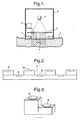
Fig. 2 is a schematic representation of a first implantable device embodying the invention, the device containing photo detectors and being coated with a biocompatible material; -
Fig. 3 is a schematic representation of a second implantable device embodying the invention, the device being step-like and having two detector levels; -
Fig. 4 is a schematic representation of a third implantable device embodying the invention, the device containing a multiplicity of detection areas at two different levels; -
Fig. 5 is a schematic representation of a fourth implantable device embodying the invention, the device having photo detectors placed in detector wells; -
Fig. 6 is a schematic representation of a fifth implantable device embodying the invention, the device having detection areas covered by a membrane on the top; -
Fig. 7 is a schematic representation of a sixth implantable device embodying the invention, the device having detection areas covered partly by a membrane and partly by a lid on the top; -
Fig. 8 is a schematic representation of a seventh implantable device embodying the invention, the device including electric connections and an electronic circuit device; -
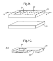
Fig. 9 is a schematic representation of an eighth implantable device embodying the invention the device including a spacer covering some of the areas of the device; -
Fig. 10 shows a section throughfigure 9 along the line X-X and shows the spacer. - In the illustrated embodiments of the invention, optical methods based on the interaction of light with compounds and body tissues are utilised. The optical methods in their general aspects correspond to those described in the literature, for example, using Beer-Lambert law and/or radiative transport theory and will not therefore be described further here.
- In the illustrated embodiments of the invention, light from a light source is incident on an implanted detector, the light is detected by a detection device in the implanted detector, and a signal is transmitted to a receiving device for analysis. The characteristics of the detected light depend on the interaction with the compounds encountered on the way from the light source to the detector.
- In the illustrated embodiments of the invention, the implanted detector is divided into areas at different levels, so that the distance for the light through the compounds, - and thus the interaction with light, varies from area to area. A differential analysis is performed on signals produced by the detector.
- Referring now to
fig. 1 , an implanteddevice 1 is placed underneath theskin 2 so that the compound to be measured is contained between the skin and the implanted device. Anoptical device 3, containing a light source 30 and alens system 5, is placed external to the skin above the implanted device, and a signal for the detected light is transferred from the implanted device to areceiver 6. - The light intensity emitted from the light source is preferably approximately constant over the whole of the implanted device. It is thereby ensured that variations in the detected light are due only to absorption in the path from light source to detector and not due to variations in emitted light intensity.
- Referring still to
fig. 1 , the light source is, for example, a light source of a broad continuous spectrum, for example a thermal white light source, depending on the compound to be measured. In the case of measuring glucose concentration, the wavelength should be well represented in the near infrared spectrum, more specifically between 1000 and 2500 nm. The light source is in this case therefore, for example, an LED, one or more laser diodes or an LED array producing wavelengths in this range. Alternatively a monochromator can be used with a white light source to select light within a desired wavelength range and directed onto the implanted device. - Wavelength specific light detection can also be obtained by covering the detectors with a film, transparent for only a specific wavelength or wavelength range. In this way is it possible to detect within a range of wavelengths simply by having a light source with a range of wavelengths and a number of detectors with different films. The film covering each detector also prevents detection of background light, as this not will pass through the film. Alternatively the detection within a range of wavelengths can be carried out by having more than one light source, and successively directing light of different wavelengths on the implanted device.
- The light absorption for some compounds is temperature dependent, meaning that the detected light on the implanted device varies with the temperature of the compounds and tissue.
Fig. 1 shows a cooling/heating device 7, such as a Pelletier element, formed as a ring around the light emitting area. With this element it is possible to perform measurements at different temperatures, so as to facilitate and improve the analysis. In case of analysis at different temperatures, the actual temperature can be recorded by a thermo element or the like, placed in thedevice 3. - Referring to
fig. 8 , the implanteddevice 1 contains a number ofphoto detectors 8, which bywires 17 are connected to anelectronic circuit device 18. The electronic circuit device can be operated by power and data transmission without the use of connecting wires to the outside. Such power transmission can be implemented by the use of a so-called inductive link, which is basically a coreless transformer. Transmission of data from the electronic circuit device to the external receiver can take place, for example, by varying the load seen by the secondary of the transformer located in the implanted device (for example, the resistance change of a photo conductivity cell), or for example, by measuring the change of resonance frequency of a series resonant circuit (for example, the change of capacitance due to the photo current in a photo diode). - Referring now to
fig. 2 , the implanted device shown here consists of a number ofdetectors 8, contained in a polymeric or elastomeric matrix with biocompatible surfaces. The shape of the detector is made step-like to provide two levels of detection areas,base level 9 and extendedlevel 10. In this way the detected light varies depending on which level the light is detected in, and-the variation is dependent on the interaction of light with compounds and components in the volume between the two levels, henceforth called themeasurement volume 11. - The implanted device can, for example, have a step-like shape in one direction, as indicated by an arrow in
fig. 3 , or a step-like shape in two directions as indicated by two arrows infig, 4 . Having more than one detector at each level increases the sensitivity of the analysis, as the signals from each level can then be averaged. - Referring now to
fig. 5 , each detector is shown placed in a detection well 12 so that only parallel light is detected. This has the effect that only the emitted and directly transmitted light is detected and not light from another light source, such as background light. - Covering the device with a
membrane 13 can reduce interference by other compounds and noise due to scattering components. The membrane is sufficiently transparent at the appropriate wavelengths employed for the measurement (if placed on top of the measurement volume), and is permeable to the compound to be measured, for example glucose, but prevents other molecules larger than the compound to be measured from entering the measurement volume. The membrane can be placed above the measurement volumes, that is, between measurement volumes and the light source and detector, and/or to the sides of the measurement volumes. Placing the membrane to the side of the measurement volume enables a long optical path length and at the same time a relatively short response time of the device with respect to changes in the concentration in the surrounding tissue and liquid. This is because a larger membrane area is available for permeation into the measurement volume and because the required diffusion length of the compound in the measurement volume can be shorter than the optical path length. The measurement volume can be filled with liquid or with a solid matrix permeable to a compound to be analysed. - The detected signal of the device is calibrated to a known concentration of the compound to be analysed, either one time for all or preferably from time to time. Measuring the concentration in a sample, taken at the same time as the optical measurement, can be used to achieve this calibration. The device however can be made self-calibrating, if two measurement volumes contain a known concentration of compound.
- In
fig. 7 a part of the device is covered with adiffusion proof lid 14 instead of with a membrane. This forms twomeasurement volumes - The formation of a bio film on the implanted device will have less effect than is the case for electrochemical devices or other devices in which the compound to be measured is consumed in the measurement process. As long as the bio film is sufficiently transparent at the optical wavelengths employed, the bio film will have very little effect on the measurement. In the case where a membrane is used, as described above, the bio film may influence the response time with respect to changes in the concentration in the surrounding tissue and liquid, but is will still have little effect on the measurement itself.
- The two levels of detection areas can be increased to three or more different levels. By increasing from two to three or more levels, the dynamic range of the sensor can be increased, as the analysis of the detected signal then discloses three or more levels corresponding to 2 or more interaction volume optical path lengths. Also more information is made available for data analysis to establish compound concentrations using, for example, chemometric, multivariant data analysis approaches. More levels also facilitate consistency and quality control of data.
- Turning now to
figure 9 , the implanted device is shown made as a laminated structure, where abase plate 19 contains the detectors, the wiring and an electronic circuit device. Thetop part 20 is laminated on the base plate, where after the base plate and the top part together forms the implantable device. - In the
top part 20 twospaces top part 20. The two spaces form two areas so that the device is able to detect light from two areas. Thespace 21 is created on the surface of the top part which faces away from the base plate so that compounds and tissue have access to the space when the device is implanted. Thespace 22 however is formed on the surface of the top part which faces towards the base plate so that compounds and tissue have no access to thespace 22 when the device is implanted, as thespace 22 is closed. This is indicated infigure 10 , showing a section through X-X of the top part offigure 9 . The detecting area underneathspace 21 andspace 22 is formed on the same surface but as thespace 22 is closed, the interaction of light with compounds and tissue occurs over a larger distance atspace 21 than atspace 22. Theclosed space 22 forms a spacer. A spacer can also be formed of a solid material transparent to the incident light. A "spacer" is to be understood as a volume in which no interaction of light with compounds and tissue occurs.
Claims (11)
- A device (1) for implantation beneath the skin (2) of a living creature, the device having outer surfaces of biocompatible material and comprising:- detection means (8) for detection of light,- transmitting means for transmitting a signal derived from said detection means to an external device,whereinsaid detection means (8) positioned at,- a first group of a plurality of substantially flat areas at a first level and- a second group of a plurality of substantially flat areas at a second level,the arrangement of the first and second groups of areas within the device is such that the distance between the skin (2) and said detection means (8), over which light from a light source (4) interacts with compounds and tissue in respect of said first group of areas differs from the distance between the skin (2) and said detection means (8), over which light from a light source interacts with compounds and tissue in respect of said second group of areas.
- A device according to claim 1, wherein each area of each group of areas forms a common level, and the common levels have a predetermined spacing from each other to provide the said difference in distance over which light interacts with compounds and tissue.
- A device according to claim 2, wherein said first group of areas is formed at a base level (9) of the device and said second group of areas is formed by projections (10) from the said base level to a top level.
- A device according to claim 1, further including a spacer (21, 22), covering one of said groups of areas so that compounds and tissue are unable to fill the volume of the spacer, the spacer (21, 22)providing the difference in distance over which light interacts with compounds and tissue.
- A device according to claim 3, wherein at least one substantially flat area constituting a third area or group of areas is provided and forms a common level between said base level and said top level
- A device according to any one of claims 1 to 5, wherein at least a part of one of said areas is formed by a permeable membrane.
- A device according to claim 6, wherein the said membrane is permeable to glucose.
- A method for optically detecting the content of a compound in the body of a living creature, the method comprising:directing a light source (4) on different areas of an implanted device containing detection means, the distance, between the skin (2) and said detection means (8), over which light from a light source interacts with compounds and tissue in respect of one area differing from the distance, between the skin (2) and said detection means (8), over which light from a light source interacts with compounds and tissue in respect of another area;obtaining light-representing signals by means of said detection means (8); andanalysing the detected signals, the analysis preferably being based on the difference between the detected signals, to obtain a value for the content of a compound being detected.
- A method according to claim 8 wherein
the analysis is based on an average of signals. - A method according to claim 8 or claim 9, wherein the compound is glucose.
- A method according to claim 8, wherein the implanted device (1) is in accordance with any one of the claims 1 to 7.
Applications Claiming Priority (7)
| Application Number | Priority Date | Filing Date | Title |
|---|---|---|---|
| DK200101892 | 2001-12-17 | ||
| DK200101904 | 2001-12-17 | ||
| DKPA200101892 | 2001-12-17 | ||
| DKPA200101904 | 2001-12-17 | ||
| DKPA200200224 | 2002-02-14 | ||
| DK200200224 | 2002-02-14 | ||
| PCT/EP2002/014141 WO2003051191A1 (en) | 2001-12-17 | 2002-12-12 | Method and device for monitoring analyte concentration by optical detection |
Publications (2)
| Publication Number | Publication Date |
|---|---|
| EP1455641A1 EP1455641A1 (en) | 2004-09-15 |
| EP1455641B1 true EP1455641B1 (en) | 2008-09-03 |
Family
ID=27222572
Family Applications (1)
| Application Number | Title | Priority Date | Filing Date |
|---|---|---|---|
| EP02791814A Expired - Lifetime EP1455641B1 (en) | 2001-12-17 | 2002-12-12 | Method and device for monitoring analyte concentration by optical detection |
Country Status (6)
| Country | Link |
|---|---|
| US (1) | US7248906B2 (en) |
| EP (1) | EP1455641B1 (en) |
| AT (1) | ATE406835T1 (en) |
| AU (1) | AU2002358128A1 (en) |
| DE (1) | DE60228755D1 (en) |
| WO (1) | WO2003051191A1 (en) |
Families Citing this family (45)
| Publication number | Priority date | Publication date | Assignee | Title |
|---|---|---|---|---|
| US6001067A (en) | 1997-03-04 | 1999-12-14 | Shults; Mark C. | Device and method for determining analyte levels |
| US8527026B2 (en) | 1997-03-04 | 2013-09-03 | Dexcom, Inc. | Device and method for determining analyte levels |
| US20030032874A1 (en) | 2001-07-27 | 2003-02-13 | Dexcom, Inc. | Sensor head for use with implantable devices |
| US7613491B2 (en) | 2002-05-22 | 2009-11-03 | Dexcom, Inc. | Silicone based membranes for use in implantable glucose sensors |
| US7828728B2 (en) | 2003-07-25 | 2010-11-09 | Dexcom, Inc. | Analyte sensor |
| US8364229B2 (en) | 2003-07-25 | 2013-01-29 | Dexcom, Inc. | Analyte sensors having a signal-to-noise ratio substantially unaffected by non-constant noise |
| US7226978B2 (en) | 2002-05-22 | 2007-06-05 | Dexcom, Inc. | Techniques to improve polyurethane membranes for implantable glucose sensors |
| US7761130B2 (en) | 2003-07-25 | 2010-07-20 | Dexcom, Inc. | Dual electrode system for a continuous analyte sensor |
| US9763609B2 (en) | 2003-07-25 | 2017-09-19 | Dexcom, Inc. | Analyte sensors having a signal-to-noise ratio substantially unaffected by non-constant noise |
| JP4708342B2 (en) | 2003-07-25 | 2011-06-22 | デックスコム・インコーポレーテッド | Oxygen augmentation membrane system for use in implantable devices |
| WO2005012873A2 (en) | 2003-07-25 | 2005-02-10 | Dexcom, Inc. | Electrode systems for electrochemical sensors |
| US9135402B2 (en) | 2007-12-17 | 2015-09-15 | Dexcom, Inc. | Systems and methods for processing sensor data |
| US7920906B2 (en) | 2005-03-10 | 2011-04-05 | Dexcom, Inc. | System and methods for processing analyte sensor data for sensor calibration |
| US20050090607A1 (en) * | 2003-10-28 | 2005-04-28 | Dexcom, Inc. | Silicone composition for biocompatible membrane |
| US9247900B2 (en) | 2004-07-13 | 2016-02-02 | Dexcom, Inc. | Analyte sensor |
| US11633133B2 (en) | 2003-12-05 | 2023-04-25 | Dexcom, Inc. | Dual electrode system for a continuous analyte sensor |
| US8423114B2 (en) | 2006-10-04 | 2013-04-16 | Dexcom, Inc. | Dual electrode system for a continuous analyte sensor |
| EP2239567B1 (en) | 2003-12-05 | 2015-09-02 | DexCom, Inc. | Calibration techniques for a continuous analyte sensor |
| US8277713B2 (en) | 2004-05-03 | 2012-10-02 | Dexcom, Inc. | Implantable analyte sensor |
| US8989833B2 (en) | 2004-07-13 | 2015-03-24 | Dexcom, Inc. | Transcutaneous analyte sensor |
| WO2006127694A2 (en) | 2004-07-13 | 2006-11-30 | Dexcom, Inc. | Analyte sensor |
| US8744546B2 (en) | 2005-05-05 | 2014-06-03 | Dexcom, Inc. | Cellulosic-based resistance domain for an analyte sensor |
| US7809441B2 (en) | 2006-05-17 | 2010-10-05 | Cardiac Pacemakers, Inc. | Implantable medical device with chemical sensor and related methods |
| EP1892877B1 (en) * | 2006-08-25 | 2008-12-03 | Alcatel Lucent | Digital signal receiver with Q-monitor |
| US20200037874A1 (en) | 2007-05-18 | 2020-02-06 | Dexcom, Inc. | Analyte sensors having a signal-to-noise ratio substantially unaffected by non-constant noise |
| US8417312B2 (en) | 2007-10-25 | 2013-04-09 | Dexcom, Inc. | Systems and methods for processing sensor data |
| US8290557B2 (en) * | 2007-12-12 | 2012-10-16 | Medtronic, Inc. | Implantable optical sensor and method for use |
| US9839395B2 (en) | 2007-12-17 | 2017-12-12 | Dexcom, Inc. | Systems and methods for processing sensor data |
| US11730407B2 (en) | 2008-03-28 | 2023-08-22 | Dexcom, Inc. | Polymer membranes for continuous analyte sensors |
| US20090247855A1 (en) * | 2008-03-28 | 2009-10-01 | Dexcom, Inc. | Polymer membranes for continuous analyte sensors |
| US8682408B2 (en) | 2008-03-28 | 2014-03-25 | Dexcom, Inc. | Polymer membranes for continuous analyte sensors |
| US8583204B2 (en) | 2008-03-28 | 2013-11-12 | Dexcom, Inc. | Polymer membranes for continuous analyte sensors |
| WO2009121361A1 (en) * | 2008-03-31 | 2009-10-08 | Bmc Ventures A/S | Optic sensor device with sers |
| EP4227675B1 (en) | 2008-09-19 | 2024-12-11 | DexCom, Inc. | Particle-containing membrane and particulate electrode for analyte sensors |
| ES2338624B1 (en) * | 2008-11-07 | 2011-09-13 | Sabirmedical,S.L. | SYSTEM AND APPARATUS FOR NON-INVASIVE MEASUREMENT OF GLUCOSE LEVELS IN BLOOD. |
| GB2516259A (en) * | 2013-07-16 | 2015-01-21 | Nokia Corp | An apparatus, method and computer program for detecting physiological parameters |
| US10716500B2 (en) | 2015-06-29 | 2020-07-21 | Cardiac Pacemakers, Inc. | Systems and methods for normalization of chemical sensor data based on fluid state changes |
| CA3051963A1 (en) | 2017-01-30 | 2018-08-02 | Medibeacon Inc. | Method for non-invasive monitoring of fluorescent tracer agent with diffuse reflection corrections |
| CN108968976B (en) | 2017-05-31 | 2022-09-13 | 心脏起搏器股份公司 | Implantable medical device with chemical sensor |
| WO2019023093A1 (en) | 2017-07-26 | 2019-01-31 | Cardiac Pacemakers, Inc. | Systems and methods for disambiguation of posture |
| CN109381195B (en) | 2017-08-10 | 2023-01-10 | 心脏起搏器股份公司 | Systems and methods including electrolyte sensor fusion |
| CN109419515B (en) | 2017-08-23 | 2023-03-24 | 心脏起搏器股份公司 | Implantable chemical sensor with staged activation |
| CN109864746B (en) | 2017-12-01 | 2023-09-29 | 心脏起搏器股份公司 | Multimode analyte sensor for medical devices |
| CN109864747B (en) | 2017-12-05 | 2023-08-25 | 心脏起搏器股份公司 | Multimode analyte sensor optoelectronic interface |
| WO2022093786A1 (en) | 2020-10-29 | 2022-05-05 | Cardiac Pacemakers, Inc. | Integrated thermo-photonic chemical sensor |
Family Cites Families (9)
| Publication number | Priority date | Publication date | Assignee | Title |
|---|---|---|---|---|
| AU2245092A (en) | 1991-12-31 | 1993-07-28 | Vivascan Corporation | Blood constituent determination based on differential spectral analysis |
| AT397458B (en) * | 1992-09-25 | 1994-04-25 | Avl Verbrennungskraft Messtech | SENSOR ARRANGEMENT |
| US5995860A (en) * | 1995-07-06 | 1999-11-30 | Thomas Jefferson University | Implantable sensor and system for measurement and control of blood constituent levels |
| EP0862648B1 (en) * | 1995-11-22 | 2004-10-06 | Medtronic MiniMed, Inc. | Detection of biological molecules using chemical amplification and optical sensors |
| US5833603A (en) * | 1996-03-13 | 1998-11-10 | Lipomatrix, Inc. | Implantable biosensing transponder |
| US6507747B1 (en) | 1998-12-02 | 2003-01-14 | Board Of Regents, The University Of Texas System | Method and apparatus for concomitant structural and biochemical characterization of tissue |
| HK1040767A1 (en) | 1998-12-02 | 2002-06-21 | Ut-Battelle, Llc | In vivo biosensor apparatus and method of use |
| DE10011284B4 (en) | 2000-03-08 | 2007-06-28 | Disetronic Licensing Ag | Apparatus for in vivo measurement of the concentration of an ingredient of a body fluid |
| US6952603B2 (en) * | 2001-03-16 | 2005-10-04 | Roche Diagnostics Operations, Inc. | Subcutaneous analyte sensor |
-
2002
- 2002-12-12 DE DE60228755T patent/DE60228755D1/en not_active Expired - Lifetime
- 2002-12-12 AU AU2002358128A patent/AU2002358128A1/en not_active Abandoned
- 2002-12-12 US US10/499,596 patent/US7248906B2/en not_active Expired - Fee Related
- 2002-12-12 WO PCT/EP2002/014141 patent/WO2003051191A1/en not_active Ceased
- 2002-12-12 AT AT02791814T patent/ATE406835T1/en not_active IP Right Cessation
- 2002-12-12 EP EP02791814A patent/EP1455641B1/en not_active Expired - Lifetime
Also Published As
| Publication number | Publication date |
|---|---|
| AU2002358128A1 (en) | 2003-06-30 |
| US7248906B2 (en) | 2007-07-24 |
| ATE406835T1 (en) | 2008-09-15 |
| WO2003051191A1 (en) | 2003-06-26 |
| EP1455641A1 (en) | 2004-09-15 |
| DE60228755D1 (en) | 2008-10-16 |
| US20050070770A1 (en) | 2005-03-31 |
Similar Documents
| Publication | Publication Date | Title |
|---|---|---|
| US7248906B2 (en) | Method and device for monitoring analyte concentration by optical detection | |
| KR100695761B1 (en) | Noninvasive Continuous Blood Glucose Monitoring | |
| US20110118570A1 (en) | Optic sensor device with sers | |
| US5666956A (en) | Instrument and method for non-invasive monitoring of human tissue analyte by measuring the body's infrared radiation | |
| TWI284200B (en) | Compact apparatus for noninvasive measurement of glucose through near-infrared spectroscopy | |
| US11224365B2 (en) | Implantable sensor and method for detecting at least one analyte in a body fluid | |
| JP3692116B2 (en) | Subcutaneous specimen sensor | |
| US20100160749A1 (en) | Implantable optical glucose sensing | |
| HK201896A (en) | Process and device for glucose determination in a biological matrix | |
| JPH07311196A (en) | Analytical monitoring system for substances to be analyzed in patient blood | |
| IL94822A (en) | Method and apparatus for determining the characteristics of a fluid having a biological analyte. | |
| WO2001016577A1 (en) | Method for determination of analytes using nir, adjacent visible spectrum and discrete nir wavelengths | |
| CN105307559A (en) | Apparatus and methods for detecting optical signals from implanted sensors | |
| JP2011519635A (en) | Optical microneedle spectrometer | |
| EP3458836B1 (en) | Non-invasive blood analysis | |
| WO1999056616A1 (en) | Non-invasive measurement of blood glucose | |
| EP4175538A1 (en) | Device for non-invasive blood glucose concentration measurement | |
| WO2009008932A2 (en) | Implantable wireless cmos biosensor | |
| EP3813643A1 (en) | Fully implantable sensor element and method for detecting at least one analyte in a body fluid | |
| KR100883153B1 (en) | Non-invasive measuring device of blood sugar level | |
| US7565249B2 (en) | Method for the determination of a light transport parameter in a biological matrix | |
| CN220275597U (en) | Blood glucose detecting system and blood glucose meter based on laser transmission type | |
| EP2319394A1 (en) | Non-invasive device and method for monitoring analytes in biological samples |
Legal Events
| Date | Code | Title | Description |
|---|---|---|---|
| PUAI | Public reference made under article 153(3) epc to a published international application that has entered the european phase |
Free format text: ORIGINAL CODE: 0009012 |
|
| 17P | Request for examination filed |
Effective date: 20040610 |
|
| AK | Designated contracting states |
Kind code of ref document: A1 Designated state(s): AT BE BG CH CY CZ DE DK EE ES FI FR GB GR IE IT LI LU MC NL PT SE SI SK TR |
|
| AX | Request for extension of the european patent |
Extension state: AL LT LV MK RO |
|
| 17Q | First examination report despatched |
Effective date: 20070614 |
|
| GRAP | Despatch of communication of intention to grant a patent |
Free format text: ORIGINAL CODE: EPIDOSNIGR1 |
|
| GRAS | Grant fee paid |
Free format text: ORIGINAL CODE: EPIDOSNIGR3 |
|
| GRAA | (expected) grant |
Free format text: ORIGINAL CODE: 0009210 |
|
| AK | Designated contracting states |
Kind code of ref document: B1 Designated state(s): AT BE BG CH CY CZ DE DK EE ES FI FR GB GR IE IT LI LU MC NL PT SE SI SK TR |
|
| REG | Reference to a national code |
Ref country code: GB Ref legal event code: FG4D |
|
| REG | Reference to a national code |
Ref country code: CH Ref legal event code: EP |
|
| REG | Reference to a national code |
Ref country code: IE Ref legal event code: FG4D |
|
| REF | Corresponds to: |
Ref document number: 60228755 Country of ref document: DE Date of ref document: 20081016 Kind code of ref document: P |
|
| PG25 | Lapsed in a contracting state [announced via postgrant information from national office to epo] |
Ref country code: NL Free format text: LAPSE BECAUSE OF FAILURE TO SUBMIT A TRANSLATION OF THE DESCRIPTION OR TO PAY THE FEE WITHIN THE PRESCRIBED TIME-LIMIT Effective date: 20080903 Ref country code: ES Free format text: LAPSE BECAUSE OF FAILURE TO SUBMIT A TRANSLATION OF THE DESCRIPTION OR TO PAY THE FEE WITHIN THE PRESCRIBED TIME-LIMIT Effective date: 20081214 |
|
| REG | Reference to a national code |
Ref country code: GB Ref legal event code: 732E |
|
| PG25 | Lapsed in a contracting state [announced via postgrant information from national office to epo] |
Ref country code: SI Free format text: LAPSE BECAUSE OF FAILURE TO SUBMIT A TRANSLATION OF THE DESCRIPTION OR TO PAY THE FEE WITHIN THE PRESCRIBED TIME-LIMIT Effective date: 20080903 Ref country code: AT Free format text: LAPSE BECAUSE OF FAILURE TO SUBMIT A TRANSLATION OF THE DESCRIPTION OR TO PAY THE FEE WITHIN THE PRESCRIBED TIME-LIMIT Effective date: 20080903 Ref country code: FI Free format text: LAPSE BECAUSE OF FAILURE TO SUBMIT A TRANSLATION OF THE DESCRIPTION OR TO PAY THE FEE WITHIN THE PRESCRIBED TIME-LIMIT Effective date: 20080903 |
|
| NLV1 | Nl: lapsed or annulled due to failure to fulfill the requirements of art. 29p and 29m of the patents act | ||
| RAP2 | Party data changed (patent owner data changed or rights of a patent transferred) |
Owner name: DANFOSS BIONICS A/S IN LIQUIDATION |
|
| PG25 | Lapsed in a contracting state [announced via postgrant information from national office to epo] |
Ref country code: BE Free format text: LAPSE BECAUSE OF FAILURE TO SUBMIT A TRANSLATION OF THE DESCRIPTION OR TO PAY THE FEE WITHIN THE PRESCRIBED TIME-LIMIT Effective date: 20080903 |
|
| RAP2 | Party data changed (patent owner data changed or rights of a patent transferred) |
Owner name: BMC VENTURES A/S |
|
| PG25 | Lapsed in a contracting state [announced via postgrant information from national office to epo] |
Ref country code: BG Free format text: LAPSE BECAUSE OF FAILURE TO SUBMIT A TRANSLATION OF THE DESCRIPTION OR TO PAY THE FEE WITHIN THE PRESCRIBED TIME-LIMIT Effective date: 20081203 |
|
| PG25 | Lapsed in a contracting state [announced via postgrant information from national office to epo] |
Ref country code: CZ Free format text: LAPSE BECAUSE OF FAILURE TO SUBMIT A TRANSLATION OF THE DESCRIPTION OR TO PAY THE FEE WITHIN THE PRESCRIBED TIME-LIMIT Effective date: 20080903 Ref country code: PT Free format text: LAPSE BECAUSE OF FAILURE TO SUBMIT A TRANSLATION OF THE DESCRIPTION OR TO PAY THE FEE WITHIN THE PRESCRIBED TIME-LIMIT Effective date: 20090203 Ref country code: SK Free format text: LAPSE BECAUSE OF FAILURE TO SUBMIT A TRANSLATION OF THE DESCRIPTION OR TO PAY THE FEE WITHIN THE PRESCRIBED TIME-LIMIT Effective date: 20080903 |
|
| REG | Reference to a national code |
Ref country code: FR Ref legal event code: TP |
|
| PLBE | No opposition filed within time limit |
Free format text: ORIGINAL CODE: 0009261 |
|
| STAA | Information on the status of an ep patent application or granted ep patent |
Free format text: STATUS: NO OPPOSITION FILED WITHIN TIME LIMIT |
|
| PG25 | Lapsed in a contracting state [announced via postgrant information from national office to epo] |
Ref country code: DK Free format text: LAPSE BECAUSE OF FAILURE TO SUBMIT A TRANSLATION OF THE DESCRIPTION OR TO PAY THE FEE WITHIN THE PRESCRIBED TIME-LIMIT Effective date: 20080903 Ref country code: EE Free format text: LAPSE BECAUSE OF FAILURE TO SUBMIT A TRANSLATION OF THE DESCRIPTION OR TO PAY THE FEE WITHIN THE PRESCRIBED TIME-LIMIT Effective date: 20080903 Ref country code: MC Free format text: LAPSE BECAUSE OF NON-PAYMENT OF DUE FEES Effective date: 20081231 |
|
| REG | Reference to a national code |
Ref country code: CH Ref legal event code: PL |
|
| 26N | No opposition filed |
Effective date: 20090604 |
|
| PG25 | Lapsed in a contracting state [announced via postgrant information from national office to epo] |
Ref country code: IT Free format text: LAPSE BECAUSE OF FAILURE TO SUBMIT A TRANSLATION OF THE DESCRIPTION OR TO PAY THE FEE WITHIN THE PRESCRIBED TIME-LIMIT Effective date: 20080903 |
|
| PG25 | Lapsed in a contracting state [announced via postgrant information from national office to epo] |
Ref country code: CH Free format text: LAPSE BECAUSE OF NON-PAYMENT OF DUE FEES Effective date: 20081231 Ref country code: LI Free format text: LAPSE BECAUSE OF NON-PAYMENT OF DUE FEES Effective date: 20081231 Ref country code: IE Free format text: LAPSE BECAUSE OF NON-PAYMENT OF DUE FEES Effective date: 20081212 |
|
| PG25 | Lapsed in a contracting state [announced via postgrant information from national office to epo] |
Ref country code: SE Free format text: LAPSE BECAUSE OF FAILURE TO SUBMIT A TRANSLATION OF THE DESCRIPTION OR TO PAY THE FEE WITHIN THE PRESCRIBED TIME-LIMIT Effective date: 20081203 |
|
| REG | Reference to a national code |
Ref country code: GB Ref legal event code: 732E Free format text: REGISTERED BETWEEN 20100624 AND 20100630 |
|
| PG25 | Lapsed in a contracting state [announced via postgrant information from national office to epo] |
Ref country code: LU Free format text: LAPSE BECAUSE OF NON-PAYMENT OF DUE FEES Effective date: 20081212 Ref country code: CY Free format text: LAPSE BECAUSE OF FAILURE TO SUBMIT A TRANSLATION OF THE DESCRIPTION OR TO PAY THE FEE WITHIN THE PRESCRIBED TIME-LIMIT Effective date: 20080903 |
|
| PG25 | Lapsed in a contracting state [announced via postgrant information from national office to epo] |
Ref country code: TR Free format text: LAPSE BECAUSE OF FAILURE TO SUBMIT A TRANSLATION OF THE DESCRIPTION OR TO PAY THE FEE WITHIN THE PRESCRIBED TIME-LIMIT Effective date: 20080903 |
|
| REG | Reference to a national code |
Ref country code: FR Ref legal event code: TP |
|
| PG25 | Lapsed in a contracting state [announced via postgrant information from national office to epo] |
Ref country code: GR Free format text: LAPSE BECAUSE OF FAILURE TO SUBMIT A TRANSLATION OF THE DESCRIPTION OR TO PAY THE FEE WITHIN THE PRESCRIBED TIME-LIMIT Effective date: 20081204 |
|
| PGFP | Annual fee paid to national office [announced via postgrant information from national office to epo] |
Ref country code: DE Payment date: 20131204 Year of fee payment: 12 Ref country code: GB Payment date: 20131211 Year of fee payment: 12 |
|
| PGFP | Annual fee paid to national office [announced via postgrant information from national office to epo] |
Ref country code: FR Payment date: 20131209 Year of fee payment: 12 |
|
| REG | Reference to a national code |
Ref country code: DE Ref legal event code: R119 Ref document number: 60228755 Country of ref document: DE |
|
| GBPC | Gb: european patent ceased through non-payment of renewal fee |
Effective date: 20141212 |
|
| REG | Reference to a national code |
Ref country code: FR Ref legal event code: ST Effective date: 20150831 |
|
| PG25 | Lapsed in a contracting state [announced via postgrant information from national office to epo] |
Ref country code: DE Free format text: LAPSE BECAUSE OF NON-PAYMENT OF DUE FEES Effective date: 20150701 Ref country code: GB Free format text: LAPSE BECAUSE OF NON-PAYMENT OF DUE FEES Effective date: 20141212 |
|
| PG25 | Lapsed in a contracting state [announced via postgrant information from national office to epo] |
Ref country code: FR Free format text: LAPSE BECAUSE OF NON-PAYMENT OF DUE FEES Effective date: 20141231 |