EP1455526A2 - Image compensation apparatus - Google Patents
Image compensation apparatus Download PDFInfo
- Publication number
- EP1455526A2 EP1455526A2 EP04005134A EP04005134A EP1455526A2 EP 1455526 A2 EP1455526 A2 EP 1455526A2 EP 04005134 A EP04005134 A EP 04005134A EP 04005134 A EP04005134 A EP 04005134A EP 1455526 A2 EP1455526 A2 EP 1455526A2
- Authority
- EP
- European Patent Office
- Prior art keywords
- information
- section
- attitude
- image pickup
- aircraft
- Prior art date
- Legal status (The legal status is an assumption and is not a legal conclusion. Google has not performed a legal analysis and makes no representation as to the accuracy of the status listed.)
- Withdrawn
Links
Images

Classifications
-
- B—PERFORMING OPERATIONS; TRANSPORTING
- B64—AIRCRAFT; AVIATION; COSMONAUTICS
- B64D—EQUIPMENT FOR FITTING IN OR TO AIRCRAFT; FLIGHT SUITS; PARACHUTES; ARRANGEMENT OR MOUNTING OF POWER PLANTS OR PROPULSION TRANSMISSIONS IN AIRCRAFT
- B64D47/00—Equipment not otherwise provided for
- B64D47/08—Arrangements of cameras
-
- H—ELECTRICITY
- H04—ELECTRIC COMMUNICATION TECHNIQUE
- H04N—PICTORIAL COMMUNICATION, e.g. TELEVISION
- H04N13/00—Stereoscopic video systems; Multi-view video systems; Details thereof
- H04N13/20—Image signal generators
- H04N13/204—Image signal generators using stereoscopic image cameras
- H04N13/246—Calibration of cameras
-
- H—ELECTRICITY
- H04—ELECTRIC COMMUNICATION TECHNIQUE
- H04N—PICTORIAL COMMUNICATION, e.g. TELEVISION
- H04N13/00—Stereoscopic video systems; Multi-view video systems; Details thereof
- H04N13/20—Image signal generators
- H04N13/296—Synchronisation thereof; Control thereof
-
- H—ELECTRICITY
- H04—ELECTRIC COMMUNICATION TECHNIQUE
- H04N—PICTORIAL COMMUNICATION, e.g. TELEVISION
- H04N23/00—Cameras or camera modules comprising electronic image sensors; Control thereof
- H04N23/60—Control of cameras or camera modules
- H04N23/68—Control of cameras or camera modules for stable pick-up of the scene, e.g. compensating for camera body vibrations
-
- H—ELECTRICITY
- H04—ELECTRIC COMMUNICATION TECHNIQUE
- H04N—PICTORIAL COMMUNICATION, e.g. TELEVISION
- H04N23/00—Cameras or camera modules comprising electronic image sensors; Control thereof
- H04N23/60—Control of cameras or camera modules
- H04N23/68—Control of cameras or camera modules for stable pick-up of the scene, e.g. compensating for camera body vibrations
- H04N23/681—Motion detection
- H04N23/6812—Motion detection based on additional sensors, e.g. acceleration sensors
Definitions
- the present invention relates to an image compensation apparatus, and particularly to an image compensation apparatus for compensating an attitude of image pickup section capable of rotating around three axes (roll axis, pitch axis and yaw axis) .
- an enhanced vision system in which a small display (Head Mounted Display: hereinafter called “HMD”) is mounted on a head of a pilot and also a camera is installed on an aircraft through a predetermined driving device and a sight line direction of the pilot is detected by measuring movement of the head of the pilot and the camera is driven according to the detected sight line direction is proposed (for example, see patent reference 2).
- HMD Head Mounted Display
- the driving device used in the image information providing system as described above has a structure in which a camera can be rotated only around two axes (pitch axis and yaw axis) , so that a pilot (or a co-pilot) visually identifying image information provided by this system may have physiological discomfort.
- An object of the invention is,to solve physiological discomfort of a pilot caused by a contradiction between image information obtained from eyes by the pilot and space information obtained from another organ in an image compensation apparatus for controlling an attitude of image pickup section used in an image information providing system of an aircraft.
- the invention as claimed in aspect 1 is characterized in that in an image compensation apparatus for controlling an attitude of image pickup section which is mounted in an aircraft and can rotate around a roll axis, a pitch axis and a yaw axis, the apparatus comprises sight line direction information detection section for detecting information about a sight line direction of a pilot, driving section which outputs a driving signal for rotating and driving the image pickup section with reference to the information about the sight line direction and rotates and drives the image pickup section based on this driving signal, image pickup attitude information detection section for detecting information about an attitude of the image pickup section, aircraft attitude information detection section for detecting information about an attitude of the aircraft, and correction section for correcting the driving signal with reference to the information about the attitude of the image pickup section and the information about the attitude of the aircraft.
- the driving signal for rotating and driving the image pickup section can be corrected with reference to the information about the attitude of the image pickup section detected by the image pickup attitude information detection section and the information about the attitude of the aircraft detected by the aircraft attitude information detection section.
- a driving signal for rotating and driving the image pickup section around a roll axis can be corrected based on the information about the attitude of the image pickup section (yaw angle information about.the image pickup section) and the information about the attitude of the aircraft (pitch angle information about the aircraft) . Therefore, even when the aircraft performs the pitching movement, image information in which the roll axis hardly moves can be displayed. As a result of this, a contradiction between image information obtained from eyes by the pilot and space information obtained from vestibular organs can be solved, so that the pilot can be prevented from getting travel-sick.
- the invention as claimed in aspect 2 is characterized in that in the image compensation apparatus as claimed in aspect 1, the image pickup section is a stereo camera constructed of two cameras placed at a predetermined spacing.
- the invention as claimed in aspect 3 is characterized in that in the image compensation apparatus as claimed in aspect 1 or 2, the information about the attitude of the image pickup section is yaw angle information about the image pickup section and the information about the attitude of the aircraft is pitch angle information about an aircraft and the correction section corrects a driving signal for rotating and driving the image pickup section around a roll axis.
- the invention as claimed in aspect 4 is characterized in that in the image compensation apparatus as claimed in any one of aspects 1 to 3, there is provided driving prevention section for preventing rotation and driving of the image pickup section when the information about the sight line direction does not reach a predetermined level.
- driving prevention section for preventing rotation and driving of the image pickup section when the information about the sight line direction does not reach a predetermined level, so that when a pilot does not desire a change in image information, a situation in which the image pickup section rotates and the image information changes due to small movement of an aircraft or the pilot can be prevented. Therefore, stable image information can be provided for the pilot, so that the pilot does not have physiological discomfort.
- the image information providing system comprises an HMD mounted on a head of a pilot and a stereo camera mounted in an aircraft, and the image compensation apparatus according to the embodiment functions so as to:control an attitude of the stereo camera.
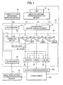
- Fig. 1 is a block diagram describing the configuration of the image compensation apparatus
- Fig. 2 is a schematic diagram of image pickup section (stereo camera 100) controlled by the image compensation apparatus shown in Fig. 1.
- the image compensation apparatus is an apparatus for controlling an attitude of the stereo camera 100 (see Fig. 2) capable of rotating around a roll axis A 1 , a pitch axis A 2 and a yaw axis A 3 orthogonal mutually.
- the stereo camera 100 is constructed of two cameras 110 placed at a predetermined spacing and is installed in the lower front of a fuselage B of an aircraft through a stereo camera driving device 200.
- the image compensation apparatus comprises sight line direction information detection section 10, a computation device 20, the stereo camera driving device 200, image pickup attitude information detection section 30, aircraft attitude information detection section 40, correction section 50, driving prevention section 60 and so on.
- the sight line direction information detection section 10 is means for detecting information about a sight line direction of a pilot.
- information head roll angle information ⁇ T , head yaw angle information ⁇ T and head pitch angle information ⁇ T ) about an attitude of a head of the pilot is adopted as the "information about the sight line direction".
- the information about the attitude of the head of the pilot detected by the sight line direction information detection section 10 is outputted to the computation device 20.
- the sight line direction information detection section 10 can be constructed of an HMD 70 mounted. on the head of the pilot and a three-axis gyro sensor mounted in the fuselage. Further, the sight line direction information detection section 10 can be constructed of a sensor (a magnetic sensor, a light wave sensor, a super-sound wave sensor, etc.) mounted in the HMD 70 and signal (a magnetic signal, a light wave. signal, a super-sound wave signal, etc.) generation section mounted in the aircraft.
- a sensor a magnetic sensor, a light wave sensor, a super-sound wave sensor, etc.
- the computation device 20 is a device for outputting a driving signal for rotating and driving the stereo camera 100 with reference to the information about the sight line direction detected by the sight line direction information detection section 10.
- the computation device 20 comprises a low-pass filter 21, limiters 22, A/D converters 23, the correction section 50, the driving prevention section 60 and so on.
- the low-pass filter 21 is a filter for eliminating high-frequency noise by passing only a low-frequency portion (about several tens Hz or lower) of the information (head roll angle information ⁇ T , head yaw angle information ⁇ T and head pitch angle information ⁇ T ) detected by the sight line direction information detection section 10, and eliminates an influence of vibration of the fuselage.
- the limiter 22 performs a function of limiting a rotational angle of the camera 110 in order to prevent the two cameras 110 of the stereo camera 100 from abutting on the fuselage B.
- a rotational angle (roll angle ⁇ ) around the roll axis A 1 a rotational angle (pitch angle ⁇ ) around the pitch axis A 2 and a rotational angle (yaw angle ⁇ ) around the yaw axis A 3 of the stereo camera 100 are limited to a range in which the stereo camera 100 does not abut on the fuselage B.
- ranges of these roll angle ⁇ , pitch angle ⁇ and yaw angle ⁇ are determined by a mounting position of the stereo camera driving device 200 with respect to the fuselage B.
- the case that the camera 110 of the right side with respect to a flight direction of the fuselage B inclines downward from a predetermined reference position is set to a roll angle of "plus”, and the case that the two cameras 110 turn upward from a predetermined reference position is set to a pitch angle of "plus”, and the case that the two cameras 110 turn rightward from a predetermined reference position is set to a yaw angle of "plus.”
- the stereo camera driving device 200 is a device for changing an attitude of the stereo camera 100 by rotating and driving the stereo camera 100 based on the driving signal outputted by the computation device 20.
- the computation device 20 and the stereo camera driving device 200 construct driving section in the invention.
- the image pickup attitude information detection section 30 is means for detecting information about an attitude of the stereo camera 100.
- yaw angle information ⁇ (a rotational angle around the yaw axis A 3 ) about the stereo camera 100 is adopted as the "information about an attitude of the stereo camera 100".
- the aircraft attitude information detection section 40 is means for detecting information about an attitude of the aircraft.
- pitch angle information ⁇ B an angle between a horizontal plane and a back-and-forth axis of the fuselage
- An inertial device using gyro or a device using electromagnetic waves such as light or radio waves can be adopted as the image pickup attitude information detection section 30 and the aircraft attitude information detection section 40.
- the correction section 50 is means for correcting the driving signal for rotating and driving the stereo camera 100 based on the information about an attitude of the stereo camera 100 (yaw angle information ⁇ about the stereo camera 100) and the information about an attitude of the aircraft (pitch angle information ⁇ B about the fuselage) and is provided inside the computation device 20.
- the correction section 50 in the embodiment calculates correction roll angle information ⁇ F by calculating correction angle information ⁇ c using the yaw angle information ⁇ about the stereo camera 100 and the pitch angle information ⁇ B about the fuselage and subtracting this correction angle information ⁇ c from the head roll angle information ⁇ T detected by the sight line direction information detection section 10. That is, the following formula is obtained.
- ⁇ F ⁇ T - ⁇ c
- the correction angle information ⁇ c is calculated by the following formula.
- ⁇ c ⁇ B sin ⁇ Incidentally, the pitch angle information ⁇ B about the fuselage and the yaw angle information ⁇ about the stereo camera 100 are converted into digital signals by the A/D converters 23.
- the driving prevention section 60 is means for preventing rotation and driving of the stereo camera 100 when the information about a sight line direction detected by the sight line direction information detection section 10 does not reach a predetermined level, and is provided inside the computation device 20.
- the driving prevention section 60 prevents an output of a driving signal to the stereo camera driving device 200 when absolute values of the head roll angle information ⁇ T , the head yaw angle information ⁇ T and the head pitch angle information ⁇ T detected by the sight line direction information detection section 10 are less than definition values ⁇ 0 , ⁇ 0 , ⁇ 0 predefined.
- the sight line direction information detection section 10 detects information (head yaw angle information ⁇ T ) about an attitude of the head of the pilot.
- the head yaw angle information ⁇ T detected by the sight line direction information detection section 10 is outputted to the computation device 20 and reaches the driving prevention section 60 through the low-pass filter 21.
- the head yaw angle information ⁇ T is transmitted to the stereo camera driving device 200 through the limiter 22 as it is.
- the driving prevention section 60 prevents an output of a driving signal to the stereo camera driving device 200.
- the stereo camera driving device 200 rotates the stereo camera 100 around the yaw axis A 3 based on this head yaw angle information ⁇ T .
- the image pickup attitude information detection section 30 detects yaw angle information ⁇ about the stereo camera 100. Then, the yaw angle information ⁇ detected by the image pickup attitude information detection section 30 is converted into a digital signal by the A/D converter 23 and thereafter is transmitted to the correction 'section 50 of the computation device 20.
- the aircraft attitude information detection section 40 detects pitch angle information ⁇ B about a fuselage.
- the pitch angle information ⁇ B detected by the aircraft attitude information detection section 40 is transmitted to the correction section 50 of the computation device 20 through the A/D converter 23.
- the correction section 50 calculates correction roll angle information ⁇ F with reference to the yaw angle information ⁇ detected by the image pickup attitude information detection section 30 and the pitch angle information ⁇ B detected by the aircraft attitude information detection section 40, and corrects a driving signal for rotating and driving the stereo camera 100.
- the correction roll angle information ⁇ F is calculated as the following formula using the formula (1) and formula (2) described above.
- the head roll angle information ⁇ T detected is 0° and if this information ⁇ T is inputted to the stereo camera driving device 200 as it is, a head roll ⁇ of the stereo camera 100 does not incline from a predetermined reference position but in the embodiment, the correction roll angle information ⁇ F (-15° ) calculated by the correction section 50 is inputted to the stereo camera driving device 200, so that the stereo camera 100 inclines 15° to the left side from the predetermined reference position.
- the stereo camera driving device 200 so that the stereo camera 100 inclines 15° to the left side from the predetermined reference position.
- a driving signal can be corrected with reference to the yaw angle information ⁇ about the stereo camera 100 detected by the image pickup attitude information detection section 30 and the pitch angle information ⁇ B about the fuselage detected by the aircraft attitude information detection section 40.
- the amount of rotation and driving around the roll axis A 1 of the stereo camera 100 can be corrected by calculating the correction roll angle information ⁇ F based on the yaw angle information ⁇ about the stereo camera 100 and the pitch angle information ⁇ B about the fuselage. Therefore, the pilot does not have an illusion that the aircraft performs roll.movement. As a result of this, a contradiction between image information obtained from the HMD 70 by the pilot and space information obtained fromvestibular organs can be solved, so that the pilot can be prevented from getting travel-sick.
- rotation and driving of the stereo camera 100 can be prevented by the driving prevention section 60 when absolute values of information (the head roll angle information ⁇ T , the head yaw angle information ⁇ T and the head pitch angle information ⁇ T ) detectedby the sight line direction information detection section 10 are less than definition values ( ⁇ 0 , ⁇ 0 , ⁇ 0 ) predefined. Therefore, when the pilot does not desire a change in image information, a situation in which the stereo camera 100 rotates and the image information changes due to variations in a sight line direction caused by vibration of the fuselage or resonance of a sensor cam be prevented. As a result of this, stable image information can be provided for the pilot, so that the pilot does not have physiological discomfort including recognition of a feeling of fatigue.
- means for detecting information about an attitude of a head of a pilot is adopted as the sight line direction information detection section 10, but an eye camera for detecting movement.of eyeballs of the pilot may also be adopted as the sight line direction information detection section 10.
- the aircraft in which the image compensation apparatus according to the invention is mounted is a manned aircraft at which a pilot boards, but a kind of its aircraft is not limited. That is, the image compensation apparatus according to the invention can be mounted in various manned aircraft such as a fixed-wing aircraft, a rotary-wing aircraft or an airship.
- the image compensation apparatus can be applied to an aircraft for performing remote control above ground.
- a ground.operator wears a display such as the HMD 70 mounting the sight line direction information detection section 10 and devices other than this display are mounted in a fuselage and thereby operation can be performed.
- a driving signal can be corrected with reference to information about an attitude of image pickup section detected by image pickup attitude information detection section and information about an attitude of an aircraft detected by aircraft attitude information detection section.
- the amount of rotation and driving around a roll axis of the image pickup section can be corrected based on a yaw angle of the image pickup section and a pitch angle of the fuselage.
- driving prevention section for preventing rotation and driving of image pickup section when information about a sight line direction does not reach a predetermined level, so that when a pilot does not desire a change in visibility information, a situation in which the image pickup section rotates and the.image information changes due to variations in the sight line direction caused by vibration of a fuselage or resonance of a sensor can be prevented. Therefore, stable image information can be provided for the pilot, so that the pilot does not have physiological discomfort including recognition of a feeling of fatigue.
Landscapes
- Engineering & Computer Science (AREA)
- Multimedia (AREA)
- Signal Processing (AREA)
- Aviation & Aerospace Engineering (AREA)
- Studio Devices (AREA)
- Closed-Circuit Television Systems (AREA)
- Stereoscopic And Panoramic Photography (AREA)
Abstract
Description
Claims (4)
- An image compensation apparatus for controlling an attitude of image pickup section which is mounted in an aircraft and is rotatable around a roll axis, a pitch axis and a yaw axis, comprising:sight line direction information detection section for detecting information about a sight line direction of a pilot,driving section which outputs a driving signal for rotating and driving the image pickup section with reference to the information about the sight line direction and rotates and drives the image pickup section based on the driving signal,image pickup attitude information detection section for detecting information about an attitude of the image pickup section,aircraft attitude information detection, section for detecting information about an attitude of the aircraft, andcorrection section for correcting the driving signal with reference to the information about the attitude of the image pickup section and the information about the attitude of the aircraft.
- The image compensation apparatus as claimed in claim 1, wherein
the image pickup section is a stereo camera constructed of two cameras placed at a predetermined spacing. - The image compensation apparatus as claimed in. claim 1 or 2, wherein
the information about the attitude of the image pickup section is yaw angle information about the image pickup section,
the information about the attitude of the aircraft is pitch angle information about a fuselage, and
the correction section corrects a driving signal for rotating and driving the image pickup section around a roll axis. - The image compensation apparatus as in claim 1, 2 or 3, further comprising:driving prevention section for preventing rotation and driving of the image pickup section when the information about the sight line direction does not reach a predetermined level.
Applications Claiming Priority (2)
| Application Number | Priority Date | Filing Date | Title |
|---|---|---|---|
| JP2003057990A JP4328551B2 (en) | 2003-03-05 | 2003-03-05 | Imaging posture control device |
| JP2003057990 | 2003-03-05 |
Publications (2)
| Publication Number | Publication Date |
|---|---|
| EP1455526A2 true EP1455526A2 (en) | 2004-09-08 |
| EP1455526A3 EP1455526A3 (en) | 2009-11-18 |
Family
ID=32821196
Family Applications (1)
| Application Number | Title | Priority Date | Filing Date |
|---|---|---|---|
| EP04005134A Withdrawn EP1455526A3 (en) | 2003-03-05 | 2004-03-04 | Image compensation apparatus |
Country Status (4)
| Country | Link |
|---|---|
| US (1) | US6999005B2 (en) |
| EP (1) | EP1455526A3 (en) |
| JP (1) | JP4328551B2 (en) |
| CA (1) | CA2459446C (en) |
Cited By (1)
| Publication number | Priority date | Publication date | Assignee | Title |
|---|---|---|---|---|
| CN102457752A (en) * | 2010-11-05 | 2012-05-16 | 索尼公司 | Imaging apparatus, image processing apparatus, and image processing method, and program |
Families Citing this family (21)
| Publication number | Priority date | Publication date | Assignee | Title |
|---|---|---|---|---|
| JP2006139015A (en) * | 2004-11-11 | 2006-06-01 | Fujinon Corp | Lens system for stereo camera |
| US8780174B1 (en) * | 2010-10-12 | 2014-07-15 | The Boeing Company | Three-dimensional vision system for displaying images taken from a moving vehicle |
| JP6026088B2 (en) | 2011-08-09 | 2016-11-16 | 株式会社トプコン | Remote control system |
| WO2013033954A1 (en) | 2011-09-09 | 2013-03-14 | 深圳市大疆创新科技有限公司 | Gyroscopic dynamic auto-balancing ball head |
| US8903654B2 (en) * | 2012-06-20 | 2014-12-02 | Raytheon Company | Non-causal attitude estimation for real-time motion compensation of sensed images on a moving platform |
| US20140090984A1 (en) * | 2012-10-01 | 2014-04-03 | Alcoa Inc. | Systems and methods for stereoscopic imaging of aluminum electrolysis pot tending operations |
| WO2014140356A1 (en) * | 2013-03-15 | 2014-09-18 | Freefly Systems Inc. | Method for enabling manual adjustment of a pointing direction of an actively stabilized camera |
| US8903568B1 (en) | 2013-07-31 | 2014-12-02 | SZ DJI Technology Co., Ltd | Remote control method and terminal |
| JP2016541026A (en) | 2013-10-08 | 2016-12-28 | エスゼット ディージェイアイ テクノロジー カンパニー リミテッドSz Dji Technology Co.,Ltd | Apparatus and method for stabilization and vibration reduction |
| KR101429166B1 (en) * | 2013-12-27 | 2014-08-13 | 대한민국 | Imaging system on aerial vehicle |
| US9900511B2 (en) | 2015-04-10 | 2018-02-20 | Freefly Systems, Inc. | Method, system, and device for controlling a stabilized camera remotely |
| WO2017017675A1 (en) * | 2015-07-28 | 2017-02-02 | Margolin Joshua | Multi-rotor uav flight control method and system |
| CN113311878B (en) * | 2016-05-31 | 2024-09-10 | 深圳市大疆灵眸科技有限公司 | Method and system for adaptive pan-tilt |
| CN107466385B (en) * | 2016-08-03 | 2021-06-01 | 深圳市大疆灵眸科技有限公司 | A PTZ control method and system |
| JP6335237B2 (en) | 2016-09-15 | 2018-05-30 | 株式会社Subaru | Stereo distance measuring device, stereo distance measuring method, and stereo distance measuring program |
| US20180091797A1 (en) * | 2016-09-27 | 2018-03-29 | The Boeing Company | Apparatus and method of compensating for relative motion of at least two aircraft-mounted cameras |
| JP6463319B2 (en) | 2016-10-19 | 2019-01-30 | 株式会社Subaru | Stereo distance measuring device, stereo distance measuring method, and stereo distance measuring program |
| KR101929113B1 (en) * | 2017-03-08 | 2018-12-13 | 한서대학교 산학협력단 | System for controlling remote based motion recognition |
| KR101929114B1 (en) * | 2017-03-08 | 2018-12-13 | 한서대학교 산학협력단 | Method for controlling remote based motion recognition |
| JP6775541B2 (en) | 2018-04-03 | 2020-10-28 | 株式会社Subaru | Position measurement method and position measurement system |
| CN113055598B (en) * | 2021-03-25 | 2022-08-05 | 浙江商汤科技开发有限公司 | Orientation data compensation method and device, electronic equipment and readable storage medium |
Family Cites Families (9)
| Publication number | Priority date | Publication date | Assignee | Title |
|---|---|---|---|---|
| US3744387A (en) * | 1971-10-08 | 1973-07-10 | D Fuller | Camera with apparent image motion and direction compensation |
| US5523887A (en) * | 1988-01-21 | 1996-06-04 | Loral Fairchild Corporation | Stabilized imaging system |
| US5072218A (en) * | 1988-02-24 | 1991-12-10 | Spero Robert E | Contact-analog headup display method and apparatus |
| US5414521A (en) * | 1991-09-12 | 1995-05-09 | Ansley; David A. | Dynamic distortion correction apparatus and method |
| JP2609967B2 (en) | 1991-12-13 | 1997-05-14 | 日本航空電子工業株式会社 | Driving device for remote controlled object |
| US5798786A (en) * | 1996-05-07 | 1998-08-25 | Recon/Optical, Inc. | Electro-optical imaging detector array for a moving vehicle which includes two axis image motion compensation and transfers pixels in row directions and column directions |
| US6130705A (en) * | 1998-07-10 | 2000-10-10 | Recon/Optical, Inc. | Autonomous electro-optical framing camera system with constant ground resolution, unmanned airborne vehicle therefor, and methods of use |
| JP2001344597A (en) | 2000-05-30 | 2001-12-14 | Fuji Heavy Ind Ltd | Fusion vision device |
| US6477326B1 (en) * | 2000-08-31 | 2002-11-05 | Recon/Optical, Inc. | Dual band framing reconnaissance camera |
-
2003
- 2003-03-05 JP JP2003057990A patent/JP4328551B2/en not_active Expired - Fee Related
-
2004
- 2004-03-03 CA CA002459446A patent/CA2459446C/en not_active Expired - Fee Related
- 2004-03-04 US US10/792,129 patent/US6999005B2/en not_active Expired - Fee Related
- 2004-03-04 EP EP04005134A patent/EP1455526A3/en not_active Withdrawn
Cited By (1)
| Publication number | Priority date | Publication date | Assignee | Title |
|---|---|---|---|---|
| CN102457752A (en) * | 2010-11-05 | 2012-05-16 | 索尼公司 | Imaging apparatus, image processing apparatus, and image processing method, and program |
Also Published As
| Publication number | Publication date |
|---|---|
| JP4328551B2 (en) | 2009-09-09 |
| CA2459446A1 (en) | 2004-09-05 |
| JP2004271557A (en) | 2004-09-30 |
| CA2459446C (en) | 2007-01-30 |
| US20040174453A1 (en) | 2004-09-09 |
| EP1455526A3 (en) | 2009-11-18 |
| US6999005B2 (en) | 2006-02-14 |
Similar Documents
| Publication | Publication Date | Title |
|---|---|---|
| US6999005B2 (en) | Image compensation apparatus | |
| EP3177010B1 (en) | Information processing device, information processing method, and image display system | |
| US10310595B2 (en) | Information processing apparatus, information processing method, computer program, and image processing system | |
| CN104781873B (en) | Image display device, method for displaying image, mobile device, image display system | |
| JP6837805B2 (en) | Design and method of correction of vestibulo-omotor reflex in display system | |
| US10558043B2 (en) | Worn display using a peripheral view | |
| US7000469B2 (en) | Motion-tracking | |
| KR20180052713A (en) | Helmet tracker | |
| JP7247371B2 (en) | Image processing device, system, image processing method, and image processing program | |
| US20180157253A1 (en) | Multi-rotor uav flight control method and system | |
| US20180040212A1 (en) | Threat warning system adapted to a virtual reality display system and method thereof | |
| CN111866395B (en) | Stability augmentation processing module, unmanned aerial vehicle camera system and image stability augmentation processing method | |
| JP2002312117A (en) | Cylindrical image spherical image control device | |
| US8294633B2 (en) | Methods for reducing artifacts in near-to-eye display systems | |
| WO2014069090A1 (en) | Image display device, image display method, and computer program | |
| JP7024997B2 (en) | Aircraft Maneuvering System and How to Maneuver an Aircraft Using an Aircraft Maneuvering System | |
| KR20180052712A (en) | Helmet Tracker Buffeting Compensation | |
| CN205356558U (en) | System is watched in remote control and make a video recording and hold and watch end thereof | |
| KR20010104929A (en) | wireless movie camera system | |
| CN100432696C (en) | Low-altitude automatic tracking system for ground moving targets based on bionic human eye control | |
| CA2526281A1 (en) | Stabilization of the effects of jitter on a displayed image | |
| US20200192468A1 (en) | Display system and method for an aircraft | |
| JPH09163267A (en) | Optical vision device | |
| JP4075253B2 (en) | Infrared image supply device | |
| JP2021091276A (en) | Operation support method for movable body and operation support system for movable body |
Legal Events
| Date | Code | Title | Description |
|---|---|---|---|
| PUAI | Public reference made under article 153(3) epc to a published international application that has entered the european phase |
Free format text: ORIGINAL CODE: 0009012 |
|
| AK | Designated contracting states |
Kind code of ref document: A2 Designated state(s): AT BE BG CH CY CZ DE DK EE ES FI FR GB GR HU IE IT LI LU MC NL PL PT RO SE SI SK TR |
|
| AX | Request for extension of the european patent |
Extension state: AL LT LV MK |
|
| PUAL | Search report despatched |
Free format text: ORIGINAL CODE: 0009013 |
|
| AK | Designated contracting states |
Kind code of ref document: A3 Designated state(s): AT BE BG CH CY CZ DE DK EE ES FI FR GB GR HU IE IT LI LU MC NL PL PT RO SE SI SK TR |
|
| AX | Request for extension of the european patent |
Extension state: AL LT LV MK |
|
| AKX | Designation fees paid | ||
| STAA | Information on the status of an ep patent application or granted ep patent |
Free format text: STATUS: THE APPLICATION IS DEEMED TO BE WITHDRAWN |
|
| 18D | Application deemed to be withdrawn |
Effective date: 20090519 |
|
| REG | Reference to a national code |
Ref country code: DE Ref legal event code: 8566 |