EP1455422A1 - Electric contact structure, process for producing the same and electronic instrument having the same - Google Patents
Electric contact structure, process for producing the same and electronic instrument having the same Download PDFInfo
- Publication number
- EP1455422A1 EP1455422A1 EP04003672A EP04003672A EP1455422A1 EP 1455422 A1 EP1455422 A1 EP 1455422A1 EP 04003672 A EP04003672 A EP 04003672A EP 04003672 A EP04003672 A EP 04003672A EP 1455422 A1 EP1455422 A1 EP 1455422A1
- Authority
- EP
- European Patent Office
- Prior art keywords
- electronic instrument
- contact
- base material
- ruptured
- parallel part
- Prior art date
- Legal status (The legal status is an assumption and is not a legal conclusion. Google has not performed a legal analysis and makes no representation as to the accuracy of the status listed.)
- Granted
Links
- 238000000034 method Methods 0.000 title claims description 12
- 239000000463 material Substances 0.000 claims abstract description 59
- 239000002344 surface layer Substances 0.000 claims abstract description 44
- 238000005452 bending Methods 0.000 claims description 14
- 239000002184 metal Substances 0.000 description 27
- 238000003780 insertion Methods 0.000 description 10
- 230000037431 insertion Effects 0.000 description 10
- 230000005611 electricity Effects 0.000 description 9
- 230000003068 static effect Effects 0.000 description 9
- 230000000052 comparative effect Effects 0.000 description 6
- 238000007747 plating Methods 0.000 description 6
- 238000003825 pressing Methods 0.000 description 5
- 230000005540 biological transmission Effects 0.000 description 4
- 230000006866 deterioration Effects 0.000 description 4
- 239000004973 liquid crystal related substance Substances 0.000 description 4
- 238000004519 manufacturing process Methods 0.000 description 4
- 239000011248 coating agent Substances 0.000 description 3
- 238000000576 coating method Methods 0.000 description 3
- 229910000990 Ni alloy Inorganic materials 0.000 description 2
- 239000010953 base metal Substances 0.000 description 1
- 230000000694 effects Effects 0.000 description 1
- 239000010410 layer Substances 0.000 description 1
Images

Classifications
-
- H—ELECTRICITY
- H01—ELECTRIC ELEMENTS
- H01R—ELECTRICALLY-CONDUCTIVE CONNECTIONS; STRUCTURAL ASSOCIATIONS OF A PLURALITY OF MUTUALLY-INSULATED ELECTRICAL CONNECTING ELEMENTS; COUPLING DEVICES; CURRENT COLLECTORS
- H01R4/00—Electrically-conductive connections between two or more conductive members in direct contact, i.e. touching one another; Means for effecting or maintaining such contact; Electrically-conductive connections having two or more spaced connecting locations for conductors and using contact members penetrating insulation
- H01R4/58—Electrically-conductive connections between two or more conductive members in direct contact, i.e. touching one another; Means for effecting or maintaining such contact; Electrically-conductive connections having two or more spaced connecting locations for conductors and using contact members penetrating insulation characterised by the form or material of the contacting members
- H01R4/64—Connections between or with conductive parts having primarily a non-electric function, e.g. frame, casing, rail
-
- H—ELECTRICITY
- H01—ELECTRIC ELEMENTS
- H01R—ELECTRICALLY-CONDUCTIVE CONNECTIONS; STRUCTURAL ASSOCIATIONS OF A PLURALITY OF MUTUALLY-INSULATED ELECTRICAL CONNECTING ELEMENTS; COUPLING DEVICES; CURRENT COLLECTORS
- H01R12/00—Structural associations of a plurality of mutually-insulated electrical connecting elements, specially adapted for printed circuits, e.g. printed circuit boards [PCB], flat or ribbon cables, or like generally planar structures, e.g. terminal strips, terminal blocks; Coupling devices specially adapted for printed circuits, flat or ribbon cables, or like generally planar structures; Terminals specially adapted for contact with, or insertion into, printed circuits, flat or ribbon cables, or like generally planar structures
- H01R12/50—Fixed connections
- H01R12/59—Fixed connections for flexible printed circuits, flat or ribbon cables or like structures
- H01R12/592—Fixed connections for flexible printed circuits, flat or ribbon cables or like structures connections to contact elements
-
- H—ELECTRICITY
- H01—ELECTRIC ELEMENTS
- H01R—ELECTRICALLY-CONDUCTIVE CONNECTIONS; STRUCTURAL ASSOCIATIONS OF A PLURALITY OF MUTUALLY-INSULATED ELECTRICAL CONNECTING ELEMENTS; COUPLING DEVICES; CURRENT COLLECTORS
- H01R13/00—Details of coupling devices of the kinds covered by groups H01R12/70 or H01R24/00 - H01R33/00
- H01R13/648—Protective earth or shield arrangements on coupling devices, e.g. anti-static shielding
- H01R13/658—High frequency shielding arrangements, e.g. against EMI [Electro-Magnetic Interference] or EMP [Electro-Magnetic Pulse]
- H01R13/6581—Shield structure
- H01R13/6582—Shield structure with resilient means for engaging mating connector
-
- H—ELECTRICITY
- H01—ELECTRIC ELEMENTS
- H01R—ELECTRICALLY-CONDUCTIVE CONNECTIONS; STRUCTURAL ASSOCIATIONS OF A PLURALITY OF MUTUALLY-INSULATED ELECTRICAL CONNECTING ELEMENTS; COUPLING DEVICES; CURRENT COLLECTORS
- H01R13/00—Details of coupling devices of the kinds covered by groups H01R12/70 or H01R24/00 - H01R33/00
- H01R13/648—Protective earth or shield arrangements on coupling devices, e.g. anti-static shielding
- H01R13/658—High frequency shielding arrangements, e.g. against EMI [Electro-Magnetic Interference] or EMP [Electro-Magnetic Pulse]
- H01R13/6591—Specific features or arrangements of connection of shield to conductive members
- H01R13/6596—Specific features or arrangements of connection of shield to conductive members the conductive member being a metal grounding panel
Definitions
- the present invention relates to an electric contact structure, which is provided in an electronic instrument mounted on a motor vehicle as a mobile unit and is used, for example, to ground a movable part of the electronic instrument, to a process for producing the electric contact structure, and to an electronic instrument having the electric contact structure.
- a car stereo (for example, see Japanese Patent Application Laid-Open No. H10-51712) as an electronic instrument is mounted on an instrument panel of a motor vehicle as a mobile unit.
- the car stereo includes: a body of the car stereo to be mounted on the instrument panel; and a front panel as a movable part, which has a display, such as liquid crystal display, and various operation buttons.
- the instrument body i.e. body of the car stereo
- the instrument body includes a CD player, MD (mini-disc) player, DVD-ROM player for constituting a navigation system and so on.
- the front panel displays information such as map information in the navigation system and information indicating playback situation of a CD player and MD player on a liquid crystal display or the like.
- the front panel is provided with a touch switch and push button to be operated when the navigation system, CD player or MD player is driven.
- a face (hereinafter, front face) facing a user of the instrument body is provided with an insertion opening through which the CD player, MD player and DVD-ROM player can be taken into and out from the instrument body.
- the front panel is set slidably movable over the range from a position for shielding the front face to a position for opening at least a part of the front face. Therefore, the front panel is attached to the instrument body partially having a small gap therebetween.
- the car stereo positions the front panel at a position where at least a part of the front face of the instrument body is opened and then, the CD player, MD player and DVD-ROM player are taken into and out from the instrument body.
- the front panel is shifted to a position for shielding the front face and then, the operation button such as a touch switch and various push buttons are operated so as to drive the CD player, MD player and DVD-ROM player.
- the information indicating the playback situation of these players is displayed on a liquid crystal display or the like.
- the front panel is set slidably movable over the range from a position for shielding the front face to a position for opening at least a part of the front face.
- the static electricity might be charged on the front panel of the car stereo. Therefore, in the conventional electronic instrument, in order to remove the static electricity out from the electronic instrument, various electric contact structures (hereinafter, ground structures) for electrically connecting the movable part, such as the front panel, to the instrument body have been used so far.
- the sheet metal has an electrically conductive base material and a surface layer formed on a surface of the base material by means of plating or coating.
- the surface layer is electrically insulating having a significantly larger electrical resistance than that of the base material.
- an electrically conductive sheet metal member such as a sheet metal of the instrument body, to be attached to a chassis is made come in contact with the base material of the sheet metal to be attached on the front panel or the like.
- the sheet metal member and the base material of the sheet metal slide with each other, so that they are kept being electrically connected to each other. That is, in the ground structure as described above, the sheet metal member and the base material of the sheet metal are electrically connected to each other. That is, in the ground structure, the front panel and the instrument body are electrically connected to each other.
- the sheet metal member and the base material of the sheet metal are electrically connected to each other, for example, a part of the surface layer of the sheet metal is removed by grinding. That is, the sheet metal member is made come in contact with thus exposed base material of the sheet metal. Alternatively, in the ground structure, the sheet metal member is made come in contact with the base metal exposed at an end face of the sheet metal. Thus, in the ground structure, the sheet metal member and the base material of the sheet metal are electrically connected to each other.
- the removal of the surface layer by grinding or the like might cause increase in man-hour, that is, increase in cost of the electronic instrument. Further, since the grinding or the like is needed, the production yield might be deteriorated caused by excess grinding of the surface layer of the sheet metal.
- the present invention is to provide an electric contact structure comprising:
- the present invention is to provide an electronic instrument comprising the electric contact structure as described above.
- the present invention is to provide a process for producing an electric contact structure, in which a first member including an electrically conductive base material and an electrically insulating surface layer formed on a surface of the base material comes in contact with an electrically conductive second member so that the base material of the first member is electrically connected to the second member, the process comprising the steps of:
- the first member is bent so as to form the ruptured part where the surface layer is ruptured, then an electric contact is provided on the ruptured part.
- the man-hour and cost required for processing the first member can be restricted.
- the first and second members can be prevented from being scraped against each other on their rough faces.
- the contact area between the first and second members is enlarged so that a noise can be prevented from occurring when these members shift relatively to each other.
- the present invention is also to provide an electronic instrument including the electric contact structure as described above.
- the first member may be attached to one of the body of the electronic instrument and the movable part, both of which are movable relatively to each other, while the second member may be attached to the other one of the body of the electronic instrument and the movable part.
- the first member may be attached to the movable part, while the second member may be attached to the body of the electronic instrument.
- a ground structure as the electric contact structure according to a preferred embodiment of the present invention and a multifunctional electronic instrument as the electronic instrument including such a ground structure will be explained with reference to Figs. 1 ⁇ 7 and 9.
- a multifunctional electronic instrument 1 shown in Fig. 1 and so on is mounted on an instrument panel of a motor vehicle as a mobile unit.
- the multifunctional electronic instrument 1 includes a body 2 of the electronic instrument, an operation display unit 3 as a front panel, a drive mechanism 4 (shown in Figs. 2 and 3) that slidably moves the operation display unit 3 relatively to a front face 10a (explained later on), a ground structure 9 (shown in Figs. 4 and 5) as the electric contact structure, and so on.
- the body 2 of the electronic instrument includes a box-shaped casing 5, a chassis 10 (shown in Fig. 4) to be received in the casing 5, the front face 10a as a face provided in front of the casing 5, and playback devices such as a CD player 6 and so on, which are received in the casing 5.
- the casing 5 includes a plurality of standing walls 10c that are integrally formed at all sides of the front face 10a. A space zone formed by a plurality of the standing walls 10c receives the operation display unit 3 rotatably.
- Each inner face of the respective standing walls 10c located at both sides of the operation display unit 3 received in the space zone described above is provided with a guide groove 19 as a slide groove extending in the vertical direction.
- the guide groove 19 is formed becoming hollow from the inner face of the standing walls 10c.
- the guide groove 19 slidably engages with a roller 26 (explained later on) which is projectingly formed on both sides of an upper end 3a of the operation display unit 3.
- the chassis 10 is made of a sheet metal or the like, and includes a flat plate-shaped bottom chassis 11, a side chassis 12 standing up from both edges of the bottom chassis 11 in the width direction thereof and so on, as shown in Fig. 4.
- the bottom chassis 11 is piled up on a bottom wall 5a (shown in Fig. 1 or 3) of the casing 5 of the body 2 of the electronic instrument.
- the casing 5 receives a CD player 6 and MD player 7 each as a playback device and a DVD-ROM player 8 for constituting a navigation system.
- the casing 5 receives an AM/FM tuner for receiving radio broadcasting, a television tuner for receiving television broadcasting and so on.
- a user pushes a push button 18 (explained later on) or the like provided in the operation display unit 3 so as to operate these playback devices and receivers.
- the front face 10a is provided with a slit 13a for inserting a MD into the MD player 7 therethrough, an insertion opening 13b and insertion opening 13c for inserting a CD and DVD-ROM into the CD player 6 and the DVD-ROM player 8 therethrough, respectively.
- the operation display unit 3 includes a display panel 14 such as a liquid crystal display for displaying image information.
- the operation display unit 3 displays map information playbacked by the DVD-ROM player 8, images of television broadcasting received by the television tuner and so forth on the display panel 14.
- the operation display unit 3 is provided with a roller 26 at both sides of its upper end 3a.
- the roller 26 is formed in a disc-shape and provided rotatably around the axis at both sides of the upper end 3a of the operation display unit 3.
- the roller 26 protrudes from the side of the operation display unit 3.
- the roller 26 engages with the guide groove 19 and rotates around the axis, thereby being set movable along the guide groove 19.
- the roller 26 engages with the guide groove 19 having a small gap therebetween so as to smoothly slide along the guide groove 19.
- the operation display unit 3 is provided with a plurality of push buttons 18 on its surface.
- the push button 18 is operated by a user, various playback devices 6, 7 and 8 received in the casing 5 are set in operation.
- the operation display unit 3 When the push button 18 is pushed, the operation display unit 3 is shifted within the first position shown in Fig. 3, the second position shown in Fig. 1, and the third position shown in Fig. 2, which is located between the first and second positions.
- the roller 26 moves within the guide groove 19 by an action of the drive mechanism 4, thereby shifting the operation display unit 3 between the first and second positions.
- the operation display unit 3 is shifted to the first, third and second positions in sequence.
- the operation display unit 3 is also shifted to the second, third and first positions in sequence.
- a lower end 3b of the operation display unit 3 protrudes from or retires to the front face 10a and the upper end 3a of the operation display unit 3 slides along the front face 10a.
- the operation display unit 3 opens the front face 10a.
- the operation display unit 3 shields the slit 13a and opens the insertion openings 13b and 13c.
- the operation display unit 3 shields a part of the front face 10a. As shown in Fig. 1, at the second position, the operation display unit 3 shields the slit 13a and insertion openings 13b and 13c. That is, at the second position, the operation display unit 3 shields the whole front face 10a.
- the operation display unit 3 is slidingly shifted by the drive mechanism 4. That is, when the CD player is selected with the selection button, the drive mechanism 4 slidingly shifts the operation display unit 3 to the third position.
- the drive mechanism 4 slidingly shifts the operation display unit 3 to the first position at which the slit 13a and insertion openings 13b and 13c formed on the front face 10a of the chassis 10 are all opened.
- the drive mechanism 4 automatically shifts the operation display unit 3 to the second position at which the slit 13a and insertion openings 13b and 13c formed on the front face 10a of the chassis 10 are all shielded.
- the sliding shift of the operation display unit 3 is carried out when a microcomputer (not shown in the figures) or the like controls the rotational direction and/or number of revolution of a motor (explained later on) of the drive mechanism 4. That is, the microcomputer recognizes a user's operation of the push buttons 18 or insertion of a disc, then controls the rotational direction and/or number of revolution of the motor so as to slidingly shift the operation display unit 3 to the corresponding position.
- the drive mechanism 4 includes a movable member 15, motor 16 as a drive source, and power transmission part (not shown in the figures).
- the movable member 15 includes in one piece a pair of arms 20 and a connecting part 21 for connecting the pair of the arms 20 to each other.
- the arm 20 is formed in a belt-shape extending straight.
- the movable member 15 is supported by the chassis 10 on a condition that the longitudinal direction of the arm 20 crosses the front face 10a at right angles. Therefore, the movable member 15 is supported by the chassis 10 moving slidably along the longitudinal direction of the arm 20. That is, the movable member 15 is provided moving slidably in the direction crossing the front face 10a at right angles.
- an end 20a of the arm 20 near to the operation display unit 3 protrudes from or retires to the front face 10a.
- the two arms 20 are provided along respective inner surfaces of side chassis 12 of the chassis 10.
- the end 20a of each arm 20 is provided with a hole which rotatably engages with a pin provided on the corresponding side of the lower end 3b of the operation display unit 3. Therefore, the arm 20, i.e. movable member 15 rotatably supports the lower end 3b of the operation display unit 3 and shifts together with the operation display unit 3. Further, the movable member 15 is electrically connected to the operation display unit 3.
- Both ends of the connecting part 21 continue to the pair of the arms 20 and the longitudinal direction of the connecting part 21 crosses the longitudinal direction of the arm 20 at right angles.
- the connecting part 21 is formed in a belt-shape extending straight.
- the connecting part 21 continues to a parallel part 23.
- the longitudinal direction of the connecting part 23 is parallel to the longitudinal direction of the arm 20.
- the parallel part 23 is formed in a belt-shape extending straight.
- the parallel part 23 is provided with a rack 24 which engages with a gear (not shown in the figure) of the power transmission part.
- the parallel part 23 is provided with a projection 25 formed by pressing such as bending and/or drawing. That is, the parallel part 23 is bent so as to form the projection 25.
- the projection 25 is formed projectingly upward from the parallel part 23, that is, toward a contact spring piece 32 (explained later on). As shown in Figs. 6 and 7, a surface of the projection 25 is formed in a convex curved face-shape upward, that is, toward the contact spring piece 32. The projection 25 extends along the sliding direction of the movable member 15.
- the parallel part 23 corresponds to the first member defined in this specification.
- the parallel part 23, i.e. the movable member 15 is made of a sheet metal and, as shown in Figs. 6 and 7, includes an electrically conductive base material 30 and a surface layer 31 formed on both surfaces of the base material 30.
- the base material 30 is made of electrically conductive metal. Both surfaces of the base material 30 are subjected to plating or coating so as to form the surface layer 31.
- the surface layer 31 is electrically insulating, that is, has high electric resistance.
- the connecting part 21 and the arm 20, both of which continue to the parallel part 23, have the same structure as that of the parallel part 23, that is, include the base material 30 and the surface layer 31.
- a ruptured part H at which a part of the surface layer 31 is ruptured, is provided at an end of the projection 25.
- the base material 30 is exposed.
- An electric contact S defined in this specification is provided on the ruptured part H. That is, the parallel part 23 is provided with the electric contact S on its ruptured part H.
- the base material 30 is completely exposed at the ruptured part H.
- the motor 16 is attached on a bottom chassis 11 of the chassis 10.
- a pinion 27 is attached to an output shaft of the motor 16.
- the power transmission includes a plurality of gears, which engage with each other. These gears rotatably supported by the bottom chassis 11. One gear engages with the pinion 27 and the other gear engages with the rack 24.
- the drive force of the motor 16 is transmitted to the rack 24 through the power transmission part so that the movable member 15 is slidingly shifted relatively to the chassis 10 in the longitudinal direction of the arm 20. That is, by the drive force of the motor 16, the arm 20 of the movable member 15 is shifted in the inward or outward direction of the chassis 10 through a through hole (not shown in the figure) formed below the front face 10a.
- the movable member 15 is shifted in the inward or outward direction of the chassis 10 by the drive force from the motor 16. Further, when each movable member 15 shifts in the inward or outward direction of the chassis 10, the roller 26 provided in the operation display unit 3 slides along the guide groove 19.
- the operation display unit 3 falls down with its surface facing upward. Then, the operation display unit 3 is shifted to the first or the third position at which the front face 10a of the chassis 10 is opened.
- the operation display unit 3 that has been fallen down is shifted to the first position and the roller 26 is positioned at the upper end of the guide groove 19.
- the operation display unit 3 and the movable member 15 are shifted within the range between the first and second positions by the drive force from the motor 16. That is, the operation display unit 3 and the movable member 15 are provided movably relatively to the body 2 of the electronic instrument.
- the operation display unit 3 and the movable member 15 correspond to the movable part defined in this specification.
- the ground structure 9 includes the parallel part 23 as the first member and the contact spring piece 32 as the second member.
- the ground structure 9 makes the parallel part 23 and the contact spring piece 32 come in contact with each other so as to electrically connect the base material 30 of the parallel part 23 and the contact spring piece 32 to each other.
- the parallel part 23 includes the base material 30 and the surface layer 31.
- the parallel part 23 is also provided with the projection 25, at the end of which the ruptured part H is provided. A part of the surface layer 31 is ruptured so as to form the ruptured part H.
- the projection 25 is obtained by bending the parallel part 23. That is, the parallel part 23 is bent so as to form the ruptured part H where a part of the surface layer 31 is ruptured and the electrical contact S is provided on the ruptured part H.
- the parallel part 23 continues to the connecting part 21 of the movable member 15. That is, the parallel part 23 is attached to the movable part 15.
- the contact spring piece 32 is made of electrically conductive sheet metal. As shown in Figs. 4 and 5, the contact spring piece 32 includes in one piece a mount 33 and a resilient contact part 34.
- the mount 33 is attached on the bottom chassis 11 of the chassis 10, i.e. on the body 2 of the electronic instrument by a screw or the like. That is, the contact spring piece 32 is attached on the body 2 of the electronic instrument.
- the resilient contact part 34 extends toward the projection 25 provided on the parallel part 23 from the mount 33.
- the resilient contact part 34 i.e. the contact spring piece 32 comes in contact with the end of the projection 25, i.e. with the electric contact S provided on the ruptured part H, that is, comes in contact with the base material 30.
- the resilient contact part 34 comes in contact with the electric contact S on a condition that the resilient contact part 34 generates a resilient restoring force, which biases the electric contact S toward the bottom chassis 11.
- the resilient contact part 34 of the contact spring piece 32 comes in contact with the electric contact S provided on the parallel part 23. That is, in the ground structure 9, even if the movable member 15 shifts so that the contact spring piece 32 and the parallel part 23 move relatively to each other, the resilient contact part 34, i.e. the contact spring piece 32 comes in contact with the electric contact S, that is, with the base material 30.
- the base material 30 of the movable member 15 is electrically connected to the contact spring piece 32, thereby electrically connecting the operation display unit 3 to the chassis 10, that is, to the body 2 of the electronic instrument. Therefore, in the ground structure 9, the static electricity charged in the operation display unit 3 and the movable member 15 can be released outside the multifunctional electronic instrument 1 through the chassis 10, i.e. through the body 2 of the electronic instrument.
- the ground structure 9 as described above may be produced as follows. First, the flat plate-shaped parallel part 23, in which the surface layer 31 is formed on both surfaces of the base material 30, is subjected to pressing such as bending and/or drawing. The projection 25 is formed on the parallel part 23, that is, the parallel part 23 is bent. At this time, as shown in Fig. 7, a part of the surface layer 31 is ruptured at the end of the projection 25 so as to forming the ruptured part H where the base material 30 is exposed.
- the electric contact S is formed on the ruptured part H.
- the contact spring piece 32 is fixed to the chassis 10 on a condition that the resilient contact part 34 comes in contact with the electric contact S. That is, the resilient contact part 34 of the contact spring piece 32 is made come in contact with the base material 30 exposed at the electric contact S. At this time, the base material 30 of the parallel part 23 is electrically connected to the contact spring piece 32. Thus, the ground structure 9 is obtained.
- Fig. 9 An effect of the ground structure 9 as described above was actually confirmed.
- the results are shown in Fig. 9.
- Fig. 9 as for products A and B according to the present invention indicated by a solid line and an alternate long and short dash line, respectively, a plate material including the base material 30 and the surface layer 31 was subjected to bending so as to form the projection 25 and the electric contact S was formed, thereby producing the parallel part 23 as the first member. Further, as for the products A and B according to the present invention, the contact spring pieces 32 were also produced.
- the electric contact S of the parallel part 23 was made come in contact with the contact spring pieces 32, then the electric resistance between the base material 30 of the parallel part 23 and the contact spring pieces 32 was measured.
- the electric resistance when the operation display unit 3 is positioned at the first position was measured.
- the electric resistance when the operation display unit 3 is positioned at the second position was measured.
- both surfaces of the base material 30 of the parallel part 23 was subjected to plating so as to form the surface layer 31 consisting of black Zn - Ni alloy plating, in which a blacked layer is given on a surface of Zn ⁇ Ni alloy plating.
- the parallel part 23 is bent so as to form the ruptured part H which was formed by rupturing a part of the surface layer 31 and to provide the electric contact S on the ruptured part H.
- the electric contact S can be easily provided by simply bending the parallel part 23, therefore the man-hour, i.e. cost of processing the parallel part 23 can be reduced.
- the parallel part 23 can be subjected to pressing by using a die or the like, the degree of bending of the parallel part 23 can be set uniform, thereby preventing the deterioration in the production yield.
- the parallel part 23 is bent so as to form the ruptured part H which was formed by rupturing a part of the surface layer 31 and to provide the electric contact S on the ruptured part H, therefore the parallel part 23 and the contact spring piece 32 can be prevented from being scraped against each other on their rough faces.
- the contact area between the parallel part 23 and the contact spring piece 32 can be enlarged compared to a case in which the contact spring piece 32 is made come in contact with an end face of the parallel part 23 or the like. Therefore, even if the parallel part 23 and the contact spring piece 32 shift relatively to each other, a noise can be prevented from occurring.
- the multifunctional electronic instrument 1 as the electronic instrument includes the ground structure 9 as described above. Therefore, the operation display unit 3 can be securely electrically connected to the chassis 10, i.e. to the body 2 of the electronic instrument through the movable member 15. Therefore, the multifunctional electronic instrument 1 can release the static electricity charged in the operation display unit 3 to the outside through the body 2 of the electronic instrument.
- the parallel part 23 is attached to the movable member 15 and the contact spring piece 32 is attached on the body 2 of the electronic instrument. Therefore, the body 2 of the electronic instrument can be securely electrically connected to the movable member 15. Therefore, the static electricity charged in the movable member 15, i.e. in the operation display unit 3 can be released outside the multifunctional electronic instrument 1 through the body 2 of the electronic instrument.
- the projection 25 is formed so as to provide the electric contact S.
- the parallel part 23 may be bent so that the electric contact S is provided on the ruptured part H at which a part of the surface layer 31 is ruptured.
- the base material 30 of the parallel part 23 can be securely electrically connected to the contact spring piece 32.
- the parallel part 23 is attached to the movable member 15 and the contact spring piece 32 is attached on the body 2 of the electronic instrument.
- the parallel part 23 as the first member may be attached on the body 2 of the electronic instrument and the contact spring piece 32 may be attached to the movable member 15.
- the parallel part 23 as the first member may be attached to one of the body 2 of the electronic instrument and the movable member 15, while the contact spring piece 32 as the second member may be attached to the other of the body 2 of the electronic instrument and the movable member 15.
- the body 2 of the electronic instrument can be securely electrically connected to the movable member 15. Therefore, the static electricity charged in the movable member 15, i.e. in the operation display unit 3 can be released outside the multifunctional electronic instrument 1 through the body 2 of the electronic instrument.
- the base material 30 is completely exposed at the electric contact S provided on the ruptured part H. That is, no surface layer 31 remains on the surface of the base material 30 there. However, instead, on the ruptured part H, a part of the surface layer 31 may remain on the surface of the base material 30. That is, the contact spring piece 32 may be made come in contact with the electric contact S provided on the ruptured part H where a part of the surface layer 31 remains on the surface of the base material 30.
- ground structure multifunctional electronic instrument and process for producing the ground structure can be obtained.
- a ground structure 9 comprising:
- a multifunctional electronic instrument 1 comprising the ground structure 9 as defined in ADDITIONAL REMARK 1.
- the multifunctional electronic instrument 1 as defined in ADDITIONAL REMARK 2 comprising:
- the multifunctional electronic instrument 1 as defined in ADDITIONAL REMARK 2 comprising:
- the parallel part 23 is bent so as to form the ruptured part H where a part of the surface layer 31 is ruptured and the electric contact S is provided on the ruptured part H.
- the electric contact S can be easily provided by simply bending the parallel part 23, therefore the man-hour, i..e. cost of processing the parallel part 23 can be reduced.
- the parallel part 23 can be subjected to pressing by using a die or the like, the degree of bending of the parallel part 23 can be set uniform, thereby preventing the deterioration in the production yield.
- the parallel part 23 is bent so as to form the ruptured part H which was formed by rupturing a part of the surface layer 31 and to provide the electric contact S on the ruptured part H, therefore the parallel part 23 and the contact spring piece 32 can be prevented from being scraped against each other on their rough faces.
- the contact area between the parallel part 23 and the contact spring piece 32 can be enlarged compared to a case in which the contact spring piece 32 is made come in contact with an end face of the parallel part 23 or the like. Therefore, even if the parallel part 23 and the contact spring piece 32 shift relatively to each other, a noise can be prevented from occurring.
- the multifunctional electronic instrument 1 includes the ground structure 9, in which the parallel part 23 is bent so as to form the ruptured part H where a part of the surface layer 31 is ruptured and the electric contact S is provided on the ruptured part H.
- the electric contact S can be easily provided by simply bending the parallel part 23, therefore the man-hour, i.e. cost of processing the parallel part 23 can be reduced.
- the parallel part 23 can be subjected to pressing by using a die or the like, the degree of bending of the parallel part 23 can be set uniform, thereby preventing the deterioration in the production yield.
- the parallel part 23 is bent so as to form the ruptured part H which was formed by rupturing a part of the surface layer 31 and to provide the electric contact S on the ruptured part H, therefore the parallel part 23 and the contact spring piece 32 can be prevented from being scraped against each other on their rough faces.
- the contact area between the parallel part 23 and the contact spring piece 32 can be enlarged compared to a case in which the contact spring piece 32 is made come in contact with an end face of the parallel part 23 or the like. Therefore, even if the parallel part 23 and the contact spring piece 32 shift relatively to each other, a noise can be prevented from occurring.
- the parallel part 23 can be securely electrically connected to the contact spring piece 32, that is, the operation display unit 3 can be securely electrically connected to the body 2 of the electronic instrument. Therefore, the static electricity charged in the operation display unit 3 can be released to the outside through the body 2 of the electronic instrument.
- the parallel part 23 is attached to one of the body 2 of the electronic instrument and the movable member 15, while the contact spring piece 32 is attached to the other of the body 2 of the electronic instrument and the movable member 15. Therefore, the body 2 of the electronic instrument and the movable member 15 can be securely electrically connected to each other. Therefore, the static electricity charged in the movable member 15 can be released outside the multifunctional electronic instrument 1 through the body 2 of the electronic instrument.
- the parallel part 23 is attached to the movable member 15, while the contact spring piece 32 is attached to the body 2 of the electronic instrument. Therefore, the body 2 of the electronic instrument and the movable member 15 can be securely electrically connected to each other. Therefore, the static electricity charged in the movable member 15 can be released outside the multifunctional electronic instrument 1 through the body 2 of the electronic instrument.
Landscapes
- Fittings On The Vehicle Exterior For Carrying Loads, And Devices For Holding Or Mounting Articles (AREA)
- Elimination Of Static Electricity (AREA)
- Contacts (AREA)
- Shielding Devices Or Components To Electric Or Magnetic Fields (AREA)
- Push-Button Switches (AREA)
Abstract
Description
- The present invention relates to an electric contact structure, which is provided in an electronic instrument mounted on a motor vehicle as a mobile unit and is used, for example, to ground a movable part of the electronic instrument, to a process for producing the electric contact structure, and to an electronic instrument having the electric contact structure.
- A car stereo (for example, see Japanese Patent Application Laid-Open No. H10-51712) as an electronic instrument is mounted on an instrument panel of a motor vehicle as a mobile unit. The car stereo includes: a body of the car stereo to be mounted on the instrument panel; and a front panel as a movable part, which has a display, such as liquid crystal display, and various operation buttons.
- The instrument body (i.e. body of the car stereo) includes a CD player, MD (mini-disc) player, DVD-ROM player for constituting a navigation system and so on. The front panel displays information such as map information in the navigation system and information indicating playback situation of a CD player and MD player on a liquid crystal display or the like. The front panel is provided with a touch switch and push button to be operated when the navigation system, CD player or MD player is driven.
- In order to restrict a space for mounting the car stereo to the instrument panel, a face (hereinafter, front face) facing a user of the instrument body is provided with an insertion opening through which the CD player, MD player and DVD-ROM player can be taken into and out from the instrument body. Further, in the car stereo, the front panel is set slidably movable over the range from a position for shielding the front face to a position for opening at least a part of the front face. Therefore, the front panel is attached to the instrument body partially having a small gap therebetween.
- The car stereo positions the front panel at a position where at least a part of the front face of the instrument body is opened and then, the CD player, MD player and DVD-ROM player are taken into and out from the instrument body. After the CD player, MD player and DVD-ROM player are inserted into the instrument body, the front panel is shifted to a position for shielding the front face and then, the operation button such as a touch switch and various push buttons are operated so as to drive the CD player, MD player and DVD-ROM player. The information indicating the playback situation of these players is displayed on a liquid crystal display or the like.
- In the conventional car stereo, the front panel is set slidably movable over the range from a position for shielding the front face to a position for opening at least a part of the front face. The static electricity might be charged on the front panel of the car stereo. Therefore, in the conventional electronic instrument, in order to remove the static electricity out from the electronic instrument, various electric contact structures (hereinafter, ground structures) for electrically connecting the movable part, such as the front panel, to the instrument body have been used so far.
- Further, since the front panel is shifted as described above and therefore exposed to the outside, a sheet metal attached on the front panel is subjected to plating or coating for maintaining its fine sight. Therefore, the sheet metal has an electrically conductive base material and a surface layer formed on a surface of the base material by means of plating or coating. The surface layer is electrically insulating having a significantly larger electrical resistance than that of the base material.
- Therefore, in the ground structure as described above, an electrically conductive sheet metal member, such as a sheet metal of the instrument body, to be attached to a chassis is made come in contact with the base material of the sheet metal to be attached on the front panel or the like. When the front panel is shifted, the sheet metal member and the base material of the sheet metal slide with each other, so that they are kept being electrically connected to each other. That is, in the ground structure as described above, the sheet metal member and the base material of the sheet metal are electrically connected to each other. That is, in the ground structure, the front panel and the instrument body are electrically connected to each other.
- In the ground structure, when the sheet metal member and the base material of the sheet metal are electrically connected to each other, for example, a part of the surface layer of the sheet metal is removed by grinding. That is, the sheet metal member is made come in contact with thus exposed base material of the sheet metal. Alternatively, in the ground structure, the sheet metal member is made come in contact with the base metal exposed at an end face of the sheet metal. Thus, in the ground structure, the sheet metal member and the base material of the sheet metal are electrically connected to each other.
- In the ground structure as described above, the removal of the surface layer by grinding or the like might cause increase in man-hour, that is, increase in cost of the electronic instrument. Further, since the grinding or the like is needed, the production yield might be deteriorated caused by excess grinding of the surface layer of the sheet metal.
- Furthermore, when the sheet metal member is made come in contact with the base material exposed at the end face of the sheet metal, the end face of the sheet metal, which becomes rough due to burrs or the like, is scraped by the sheet metal member. Therefore, when the front panel is shifted as described above, a noise might occur.
- It is therefore an objective of the present invention to solve the above problem and to provide an electric contact structure, a process for producing the electric contact structure, and an electronic instrument having the electric contact structure, by which the cost-up and the deterioration in the yield can be prevented from occurring, and a noise can be prevented from occurring when the members coming in contact with each other are moved relatively to each other.
- In order to attain the above objective, the present invention is to provide an electric contact structure comprising:
- a first member including an electrically conductive base material and an electrically insulating surface layer formed on a surface of the base material;
- an electrically conductive second member which comes in contact with the first member;
- a ruptured part of the surface layer of the first member; and
- an electric contact formed on the ruptured part, which comes in contact with the second member, thereby electrically connecting the base material of the first member and the second member to each other.
-
- In order to attain the above objective, the present invention is to provide an electronic instrument comprising the electric contact structure as described above.
- In order to attain the above objective, the present invention is to provide a process for producing an electric contact structure, in which a first member including an electrically conductive base material and an electrically insulating surface layer formed on a surface of the base material comes in contact with an electrically conductive second member so that the base material of the first member is electrically connected to the second member, the process comprising the steps of:
- forming a ruptured part on the surface layer of the first member by bending the first member;
- forming an electric contact on the ruptured part; and
- making the second member come in contact with the electric contact formed on the ruptured part.
-
- As described above, in the electric contact structure and the process for producing the electric contact structure according to the present invention, the first member is bent so as to form the ruptured part where the surface layer is ruptured, then an electric contact is provided on the ruptured part. Thus, the man-hour and cost required for processing the first member can be restricted. Moreover, the first and second members can be prevented from being scraped against each other on their rough faces. The contact area between the first and second members is enlarged so that a noise can be prevented from occurring when these members shift relatively to each other.
- The present invention is also to provide an electronic instrument including the electric contact structure as described above.
- The first member may be attached to one of the body of the electronic instrument and the movable part, both of which are movable relatively to each other, while the second member may be attached to the other one of the body of the electronic instrument and the movable part.
- The first member may be attached to the movable part, while the second member may be attached to the body of the electronic instrument.
-
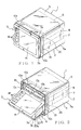
- Figure 1 is a perspective view illustrating an appearance of a multifunctional electronic instrument according to a preferred embodiment of the present invention;
- Figure 2 is a perspective view illustrating a state when an operation display unit of the multifunctional electronic instrument shown in Fig. 1 is positioned at the third position;
- Figure 3 is a perspective view illustrating a state when an operation display unit of the multifunctional electronic instrument shown in Fig. 1 is positioned at the first position;
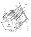
- Figure 4 is a perspective view illustrating a primary part of the multifunctional electronic instrument shown in Fig. 3;
- Figure 5 is an enlarged perspective view of a ground structure of the multifunctional electronic instrument shown in Fig. 4;
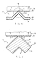
- Figure 6 is a cross sectional view taken along VI ― VI line in Fig. 5;
- Figure 7 is an enlarged illustration of the part VII shown in Fig. 6;
- Figure 8 is a cross sectional view illustrating another preferred embodiment of the ground structure shown in Fig. 6; and
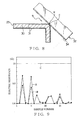
- Figure 9 is a graph illustrating measured values of electric resistance for the ground structure shown in Fig. 6 and a comparative example.
-
- In the following, a ground structure as the electric contact structure according to a preferred embodiment of the present invention and a multifunctional electronic instrument as the electronic instrument including such a ground structure will be explained with reference to Figs. 1 ― 7 and 9. A multifunctional
electronic instrument 1 shown in Fig. 1 and so on is mounted on an instrument panel of a motor vehicle as a mobile unit. - As shown in Figs. 1 ― 3, the multifunctional
electronic instrument 1 includes abody 2 of the electronic instrument, anoperation display unit 3 as a front panel, a drive mechanism 4 (shown in Figs. 2 and 3) that slidably moves theoperation display unit 3 relatively to afront face 10a (explained later on), a ground structure 9 (shown in Figs. 4 and 5) as the electric contact structure, and so on. - The
body 2 of the electronic instrument includes a box-shapedcasing 5, a chassis 10 (shown in Fig. 4) to be received in thecasing 5, thefront face 10a as a face provided in front of thecasing 5, and playback devices such as aCD player 6 and so on, which are received in thecasing 5. Thecasing 5 includes a plurality of standingwalls 10c that are integrally formed at all sides of thefront face 10a. A space zone formed by a plurality of the standingwalls 10c receives theoperation display unit 3 rotatably. - Each inner face of the respective standing
walls 10c located at both sides of theoperation display unit 3 received in the space zone described above is provided with aguide groove 19 as a slide groove extending in the vertical direction. Theguide groove 19 is formed becoming hollow from the inner face of the standingwalls 10c. Theguide groove 19 slidably engages with a roller 26 (explained later on) which is projectingly formed on both sides of anupper end 3a of theoperation display unit 3. - The
chassis 10 is made of a sheet metal or the like, and includes a flat plate-shapedbottom chassis 11, aside chassis 12 standing up from both edges of thebottom chassis 11 in the width direction thereof and so on, as shown in Fig. 4. Thebottom chassis 11 is piled up on abottom wall 5a (shown in Fig. 1 or 3) of thecasing 5 of thebody 2 of the electronic instrument. - In the example shown in the figures, the
casing 5 receives aCD player 6 andMD player 7 each as a playback device and a DVD-ROM player 8 for constituting a navigation system. Although it is not shown in the figures, thecasing 5 receives an AM/FM tuner for receiving radio broadcasting, a television tuner for receiving television broadcasting and so on. A user pushes a push button 18 (explained later on) or the like provided in theoperation display unit 3 so as to operate these playback devices and receivers. - As shown in Fig. 3, the
front face 10a is provided with aslit 13a for inserting a MD into theMD player 7 therethrough, aninsertion opening 13b andinsertion opening 13c for inserting a CD and DVD-ROM into theCD player 6 and the DVD-ROM player 8 therethrough, respectively. - The
operation display unit 3 includes adisplay panel 14 such as a liquid crystal display for displaying image information. Theoperation display unit 3 displays map information playbacked by the DVD-ROM player 8, images of television broadcasting received by the television tuner and so forth on thedisplay panel 14. - The
operation display unit 3 is provided with aroller 26 at both sides of itsupper end 3a. Theroller 26 is formed in a disc-shape and provided rotatably around the axis at both sides of theupper end 3a of theoperation display unit 3. Theroller 26 protrudes from the side of theoperation display unit 3. - The
roller 26 engages with theguide groove 19 and rotates around the axis, thereby being set movable along theguide groove 19. Theroller 26 engages with theguide groove 19 having a small gap therebetween so as to smoothly slide along theguide groove 19. - The
operation display unit 3 is provided with a plurality ofpush buttons 18 on its surface. When thepush button 18 is operated by a user,various playback devices casing 5 are set in operation. - When the
push button 18 is pushed, theoperation display unit 3 is shifted within the first position shown in Fig. 3, the second position shown in Fig. 1, and the third position shown in Fig. 2, which is located between the first and second positions. Theroller 26 moves within theguide groove 19 by an action of thedrive mechanism 4, thereby shifting theoperation display unit 3 between the first and second positions. - The
operation display unit 3 is shifted to the first, third and second positions in sequence. Theoperation display unit 3 is also shifted to the second, third and first positions in sequence. At this time, alower end 3b of theoperation display unit 3 protrudes from or retires to thefront face 10a and theupper end 3a of theoperation display unit 3 slides along thefront face 10a. - As shown in Fig. 3, at the first position, the
slit 13a andinsertion openings front face 10a are all opened. That is, at the first position, theoperation display unit 3 opens thefront face 10a. As shown in Fig. 2, at the third position, theoperation display unit 3 shields theslit 13a and opens theinsertion openings - At the third position, the
operation display unit 3 shields a part of thefront face 10a. As shown in Fig. 1, at the second position, theoperation display unit 3 shields theslit 13a andinsertion openings operation display unit 3 shields the wholefront face 10a. - For example, when a selection button (such as a button for selecting the CD player, MD player and so on) of the
push buttons 18 or an OPEN button is pushed, theoperation display unit 3 is slidingly shifted by thedrive mechanism 4. That is, when the CD player is selected with the selection button, thedrive mechanism 4 slidingly shifts theoperation display unit 3 to the third position. - When the OPEN button is pushed, the
drive mechanism 4 slidingly shifts theoperation display unit 3 to the first position at which theslit 13a andinsertion openings front face 10a of thechassis 10 are all opened. When a desired disc for the CD player, MD player or the like is inserted into or taken out from theslit 13a,insertion opening drive mechanism 4 automatically shifts theoperation display unit 3 to the second position at which theslit 13a andinsertion openings front face 10a of thechassis 10 are all shielded. - In a state when the
front face 10a is opened with theoperation display unit 3 being positioned at the first or third position, when a desired disc is inserted, then theoperation display unit 3 is automatically shifted to the second position. Thereafter, when a user pushes a palyback button of thepush buttons 18 or a search button, a playback of the corresponding disc or a search action is carried out. - The sliding shift of the
operation display unit 3 is carried out when a microcomputer (not shown in the figures) or the like controls the rotational direction and/or number of revolution of a motor (explained later on) of thedrive mechanism 4. That is, the microcomputer recognizes a user's operation of thepush buttons 18 or insertion of a disc, then controls the rotational direction and/or number of revolution of the motor so as to slidingly shift theoperation display unit 3 to the corresponding position. - The
drive mechanism 4 includes amovable member 15,motor 16 as a drive source, and power transmission part (not shown in the figures). As shown in Fig. 4, themovable member 15 includes in one piece a pair ofarms 20 and a connecting part 21 for connecting the pair of thearms 20 to each other. - The
arm 20 is formed in a belt-shape extending straight. Themovable member 15 is supported by thechassis 10 on a condition that the longitudinal direction of thearm 20 crosses thefront face 10a at right angles. Therefore, themovable member 15 is supported by thechassis 10 moving slidably along the longitudinal direction of thearm 20. That is, themovable member 15 is provided moving slidably in the direction crossing thefront face 10a at right angles. When themovable member 15 slides, anend 20a of thearm 20 near to theoperation display unit 3 protrudes from or retires to thefront face 10a. - The two
arms 20 are provided along respective inner surfaces ofside chassis 12 of thechassis 10. Theend 20a of eacharm 20 is provided with a hole which rotatably engages with a pin provided on the corresponding side of thelower end 3b of theoperation display unit 3. Therefore, thearm 20, i.e.movable member 15 rotatably supports thelower end 3b of theoperation display unit 3 and shifts together with theoperation display unit 3. Further, themovable member 15 is electrically connected to theoperation display unit 3. - Both ends of the connecting part 21 continue to the pair of the
arms 20 and the longitudinal direction of the connecting part 21 crosses the longitudinal direction of thearm 20 at right angles. The connecting part 21 is formed in a belt-shape extending straight. The connecting part 21 continues to aparallel part 23. The longitudinal direction of the connectingpart 23 is parallel to the longitudinal direction of thearm 20. Theparallel part 23 is formed in a belt-shape extending straight. - The
parallel part 23 is provided with arack 24 which engages with a gear (not shown in the figure) of the power transmission part. Theparallel part 23 is provided with aprojection 25 formed by pressing such as bending and/or drawing. That is, theparallel part 23 is bent so as to form theprojection 25. - The
projection 25 is formed projectingly upward from theparallel part 23, that is, toward a contact spring piece 32 (explained later on). As shown in Figs. 6 and 7, a surface of theprojection 25 is formed in a convex curved face-shape upward, that is, toward thecontact spring piece 32. Theprojection 25 extends along the sliding direction of themovable member 15. - The
parallel part 23 corresponds to the first member defined in this specification. Theparallel part 23, i.e. themovable member 15 is made of a sheet metal and, as shown in Figs. 6 and 7, includes an electricallyconductive base material 30 and asurface layer 31 formed on both surfaces of thebase material 30. Thebase material 30 is made of electrically conductive metal. Both surfaces of thebase material 30 are subjected to plating or coating so as to form thesurface layer 31. Thesurface layer 31 is electrically insulating, that is, has high electric resistance. The connecting part 21 and thearm 20, both of which continue to theparallel part 23, have the same structure as that of theparallel part 23, that is, include thebase material 30 and thesurface layer 31. - As shown in Fig. 7, a ruptured part H, at which a part of the
surface layer 31 is ruptured, is provided at an end of theprojection 25. At the ruptured part H, thebase material 30 is exposed. An electric contact S defined in this specification is provided on the ruptured part H. That is, theparallel part 23 is provided with the electric contact S on its ruptured part H. In an example shown in the figures, thebase material 30 is completely exposed at the ruptured part H. - The
motor 16 is attached on abottom chassis 11 of thechassis 10. Apinion 27 is attached to an output shaft of themotor 16. The power transmission includes a plurality of gears, which engage with each other. These gears rotatably supported by thebottom chassis 11. One gear engages with thepinion 27 and the other gear engages with therack 24. - Therefore, the drive force of the
motor 16 is transmitted to therack 24 through the power transmission part so that themovable member 15 is slidingly shifted relatively to thechassis 10 in the longitudinal direction of thearm 20. That is, by the drive force of themotor 16, thearm 20 of themovable member 15 is shifted in the inward or outward direction of thechassis 10 through a through hole (not shown in the figure) formed below thefront face 10a. - In the
drive mechanism 4, themovable member 15 is shifted in the inward or outward direction of thechassis 10 by the drive force from themotor 16. Further, when eachmovable member 15 shifts in the inward or outward direction of thechassis 10, theroller 26 provided in theoperation display unit 3 slides along theguide groove 19. - That is, when the
movable member 15 is shifted in the outward direction from thechassis 10 by receiving the drive force from themotor 16, theoperation display unit 3 falls down with its surface facing upward. Then, theoperation display unit 3 is shifted to the first or the third position at which thefront face 10a of thechassis 10 is opened. When themovable member 15 is shifted in the inward direction to thechassis 10, theoperation display unit 3 that has been fallen down is shifted to the first position and theroller 26 is positioned at the upper end of theguide groove 19. - The
operation display unit 3 and themovable member 15 are shifted within the range between the first and second positions by the drive force from themotor 16. That is, theoperation display unit 3 and themovable member 15 are provided movably relatively to thebody 2 of the electronic instrument. Theoperation display unit 3 and themovable member 15 correspond to the movable part defined in this specification. - As shown in Figs. 4, 5 and 7, the ground structure 9 includes the
parallel part 23 as the first member and thecontact spring piece 32 as the second member. The ground structure 9 makes theparallel part 23 and thecontact spring piece 32 come in contact with each other so as to electrically connect thebase material 30 of theparallel part 23 and thecontact spring piece 32 to each other. - As described above, the
parallel part 23 includes thebase material 30 and thesurface layer 31. Theparallel part 23 is also provided with theprojection 25, at the end of which the ruptured part H is provided. A part of thesurface layer 31 is ruptured so as to form the ruptured part H. Theprojection 25 is obtained by bending theparallel part 23. That is, theparallel part 23 is bent so as to form the ruptured part H where a part of thesurface layer 31 is ruptured and the electrical contact S is provided on the ruptured part H. Theparallel part 23 continues to the connecting part 21 of themovable member 15. That is, theparallel part 23 is attached to themovable part 15. - The
contact spring piece 32 is made of electrically conductive sheet metal. As shown in Figs. 4 and 5, thecontact spring piece 32 includes in one piece amount 33 and aresilient contact part 34. Themount 33 is attached on thebottom chassis 11 of thechassis 10, i.e. on thebody 2 of the electronic instrument by a screw or the like. That is, thecontact spring piece 32 is attached on thebody 2 of the electronic instrument. - The
resilient contact part 34 extends toward theprojection 25 provided on theparallel part 23 from themount 33. Theresilient contact part 34, i.e. thecontact spring piece 32 comes in contact with the end of theprojection 25, i.e. with the electric contact S provided on the ruptured part H, that is, comes in contact with thebase material 30. Theresilient contact part 34 comes in contact with the electric contact S on a condition that theresilient contact part 34 generates a resilient restoring force, which biases the electric contact S toward thebottom chassis 11. - In the ground structure 9 constructed as described above, even if the
movable member 15 slides as described above when theoperation display unit 3 shifts within the range between the first and second positions, theresilient contact part 34 of thecontact spring piece 32 comes in contact with the electric contact S provided on theparallel part 23. That is, in the ground structure 9, even if themovable member 15 shifts so that thecontact spring piece 32 and theparallel part 23 move relatively to each other, theresilient contact part 34, i.e. thecontact spring piece 32 comes in contact with the electric contact S, that is, with thebase material 30. - In the ground structure 9, the
base material 30 of themovable member 15 is electrically connected to thecontact spring piece 32, thereby electrically connecting theoperation display unit 3 to thechassis 10, that is, to thebody 2 of the electronic instrument. Therefore, in the ground structure 9, the static electricity charged in theoperation display unit 3 and themovable member 15 can be released outside the multifunctionalelectronic instrument 1 through thechassis 10, i.e. through thebody 2 of the electronic instrument. - The ground structure 9 as described above may be produced as follows. First, the flat plate-shaped
parallel part 23, in which thesurface layer 31 is formed on both surfaces of thebase material 30, is subjected to pressing such as bending and/or drawing. Theprojection 25 is formed on theparallel part 23, that is, theparallel part 23 is bent. At this time, as shown in Fig. 7, a part of thesurface layer 31 is ruptured at the end of theprojection 25 so as to forming the ruptured part H where thebase material 30 is exposed. - Then, the electric contact S is formed on the ruptured part H. The
contact spring piece 32 is fixed to thechassis 10 on a condition that theresilient contact part 34 comes in contact with the electric contact S. That is, theresilient contact part 34 of thecontact spring piece 32 is made come in contact with thebase material 30 exposed at the electric contact S. At this time, thebase material 30 of theparallel part 23 is electrically connected to thecontact spring piece 32. Thus, the ground structure 9 is obtained. - An effect of the ground structure 9 as described above was actually confirmed. The results are shown in Fig. 9. In Fig. 9, as for products A and B according to the present invention indicated by a solid line and an alternate long and short dash line, respectively, a plate material including the
base material 30 and thesurface layer 31 was subjected to bending so as to form theprojection 25 and the electric contact S was formed, thereby producing theparallel part 23 as the first member. Further, as for the products A and B according to the present invention, thecontact spring pieces 32 were also produced. - The electric contact S of the
parallel part 23 was made come in contact with thecontact spring pieces 32, then the electric resistance between thebase material 30 of theparallel part 23 and thecontact spring pieces 32 was measured. A plurality of samples (twenty samples) for each of the products A and B according to the present invention, each of which includes theparallel part 23 and thecontact spring piece 32, were produced, then each electric resistance of the products was measured. Here, in detail, as for each sample for the product A, the electric resistance when theoperation display unit 3 is positioned at the first position was measured. As for each sample for the product B, the electric resistance when theoperation display unit 3 is positioned at the second position was measured. - In addition, as for comparative examples C indicated by an alternate long and two short dashes line in Fig. 9, the
parallel part 23, in which theprojection 25 was not formed, that is, a part of thesurface layer 31 was not ruptured, was made come in contact with thecontact spring pieces 32, thereby producing the comparative examples C. Then, the electric resistance between thebase material 30 of theparallel part 23 and thecontact spring piece 32 was measured. As for the comparative examples C, a plurality of the samples (twenty samples), each of which includes theparallel part 23 and thecontact spring piece 32, were produced, then each electric resistance was measured. - Further, as for the products A and B according to the present invention and the comparative examples C, both surfaces of the
base material 30 of theparallel part 23 was subjected to plating so as to form thesurface layer 31 consisting of black Zn - Ni alloy plating, in which a blacked layer is given on a surface of Zn ― Ni alloy plating. - The results shown in Fig. 9 reveals that the electric resistance was 10 ohms for the comparative samples C. On the other hand, the electric resistance was at most 7 ohms for the products A and B according to the present invention and was actually 0 ohm for the most products. Thus, as for the products A and B according to the present invention, it was confirmed that the electric resistance. could be significantly reduced by providing the electric contact S on the ruptured part H which was formed by rupturing a part of the
surface layer 31. That is, it was confirmed that thebase material 30 of theparallel part 23 could be securely electrically connected to thecontact spring piece 32. - In the preferred embodiment as described above, the
parallel part 23 is bent so as to form the ruptured part H which was formed by rupturing a part of thesurface layer 31 and to provide the electric contact S on the ruptured part H. Thus, since the electric contact S can be easily provided by simply bending theparallel part 23, therefore the man-hour, i.e. cost of processing theparallel part 23 can be reduced. Further, since theparallel part 23 can be subjected to pressing by using a die or the like, the degree of bending of theparallel part 23 can be set uniform, thereby preventing the deterioration in the production yield. - Further, since the
parallel part 23 is bent so as to form the ruptured part H which was formed by rupturing a part of thesurface layer 31 and to provide the electric contact S on the ruptured part H, therefore theparallel part 23 and thecontact spring piece 32 can be prevented from being scraped against each other on their rough faces. The contact area between theparallel part 23 and thecontact spring piece 32 can be enlarged compared to a case in which thecontact spring piece 32 is made come in contact with an end face of theparallel part 23 or the like. Therefore, even if theparallel part 23 and thecontact spring piece 32 shift relatively to each other, a noise can be prevented from occurring. - The multifunctional
electronic instrument 1 as the electronic instrument includes the ground structure 9 as described above. Therefore, theoperation display unit 3 can be securely electrically connected to thechassis 10, i.e. to thebody 2 of the electronic instrument through themovable member 15. Therefore, the multifunctionalelectronic instrument 1 can release the static electricity charged in theoperation display unit 3 to the outside through thebody 2 of the electronic instrument. - The
parallel part 23 is attached to themovable member 15 and thecontact spring piece 32 is attached on thebody 2 of the electronic instrument. Therefore, thebody 2 of the electronic instrument can be securely electrically connected to themovable member 15. Therefore, the static electricity charged in themovable member 15, i.e. in theoperation display unit 3 can be released outside the multifunctionalelectronic instrument 1 through thebody 2 of the electronic instrument. - In the preferred embodiment as described above, the
projection 25 is formed so as to provide the electric contact S. However, as shown in Fig. 8, without bending theparallel part 23 so as to form theprojection 25, theparallel part 23 may be bent so that the electric contact S is provided on the ruptured part H at which a part of thesurface layer 31 is ruptured. In this case as well, thebase material 30 of theparallel part 23 can be securely electrically connected to thecontact spring piece 32. - In the preferred embodiment as described above, the
parallel part 23 is attached to themovable member 15 and thecontact spring piece 32 is attached on thebody 2 of the electronic instrument. However, instead, theparallel part 23 as the first member may be attached on thebody 2 of the electronic instrument and thecontact spring piece 32 may be attached to themovable member 15. - In short, in the present invention, the
parallel part 23 as the first member may be attached to one of thebody 2 of the electronic instrument and themovable member 15, while thecontact spring piece 32 as the second member may be attached to the other of thebody 2 of the electronic instrument and themovable member 15. In this case as well, thebody 2 of the electronic instrument can be securely electrically connected to themovable member 15. Therefore, the static electricity charged in themovable member 15, i.e. in theoperation display unit 3 can be released outside the multifunctionalelectronic instrument 1 through thebody 2 of the electronic instrument. - In the preferred embodiment as described above, the
base material 30 is completely exposed at the electric contact S provided on the ruptured part H. That is, nosurface layer 31 remains on the surface of thebase material 30 there. However, instead, on the ruptured part H, a part of thesurface layer 31 may remain on the surface of thebase material 30. That is, thecontact spring piece 32 may be made come in contact with the electric contact S provided on the ruptured part H where a part of thesurface layer 31 remains on the surface of thebase material 30. - According to the preferred embodiment described above, the following ground structure, multifunctional electronic instrument and process for producing the ground structure can be obtained.
- A ground structure 9 comprising:
- a
parallel part 23 including an electricallyconductive base material 30 and an electrically insulatingsurface layer 31 formed on a surface of thebase material 30; - an electrically conductive
contact spring piece 32, which comes in contact with theparallel part 23; - a ruptured part H of the
surface layer 31 of theparallel part 23; and - an electric contact S formed on the ruptured part H, which comes in
contact with the
contact spring piece 32, thereby electrically connecting thebase material 30 of theparallel part 23 and thecontact spring piece 32 to each other. -
- A multifunctional
electronic instrument 1 comprising the ground structure 9 as defined inADDITIONAL REMARK 1. - The multifunctional
electronic instrument 1 as defined inADDITIONAL REMARK 2 comprising: - a
body 2 of the electronic instrument; and - a
movable part 15 provided movably relatively to thebody 2 of the electronic instrument,
wherein the -
- The multifunctional
electronic instrument 1 as defined inADDITIONAL REMARK 2 comprising: - a
body 2 of the electronic instrument; and - a
movable part 15 provided movably relatively to thebody 2 of the electronic instrument,
wherein the -
- A process for producing a ground structure 9, in which a
parallel part 23 including an electricallyconductive base material 30 and an electrically insulatingsurface layer 31 formed on a surface of thebase material 30 comes in contact with an electrically conductivecontact spring piece 32 so that thebase material 30 of theparallel part 23 is electrically connected to thecontact spring piece 32, the process comprising the steps of: - forming a ruptured part H on the
surface layer 31 of theparallel part 23 by bending theparallel part 23; - forming an electric contact S on the ruptured part H; and
- making the
contact spring piece 32 come in contact with the electric contact S formed on the ruptured part H. -
- According to the ground structure 9 described in
ADDITIONAL REMARK 1 and a process for producing the ground structure described inADDITIONAL REMARK 5, theparallel part 23 is bent so as to form the ruptured part H where a part of thesurface layer 31 is ruptured and the electric contact S is provided on the ruptured part H. Thus, since the electric contact S can be easily provided by simply bending theparallel part 23, therefore the man-hour, i..e. cost of processing theparallel part 23 can be reduced. Further, since theparallel part 23 can be subjected to pressing by using a die or the like, the degree of bending of theparallel part 23 can be set uniform, thereby preventing the deterioration in the production yield. - Further, since the
parallel part 23 is bent so as to form the ruptured part H which was formed by rupturing a part of thesurface layer 31 and to provide the electric contact S on the ruptured part H, therefore theparallel part 23 and thecontact spring piece 32 can be prevented from being scraped against each other on their rough faces. The contact area between theparallel part 23 and thecontact spring piece 32 can be enlarged compared to a case in which thecontact spring piece 32 is made come in contact with an end face of theparallel part 23 or the like. Therefore, even if theparallel part 23 and thecontact spring piece 32 shift relatively to each other, a noise can be prevented from occurring. - According to the multifunctional
electronic instrument 1 described inADDITIONAL REMARK 2, the multifunctionalelectronic instrument 1 includes the ground structure 9, in which theparallel part 23 is bent so as to form the ruptured part H where a part of thesurface layer 31 is ruptured and the electric contact S is provided on the ruptured part H. Thus, since the electric contact S can be easily provided by simply bending theparallel part 23, therefore the man-hour, i.e. cost of processing theparallel part 23 can be reduced. Further, since theparallel part 23 can be subjected to pressing by using a die or the like, the degree of bending of theparallel part 23 can be set uniform, thereby preventing the deterioration in the production yield. - Further, since the
parallel part 23 is bent so as to form the ruptured part H which was formed by rupturing a part of thesurface layer 31 and to provide the electric contact S on the ruptured part H, therefore theparallel part 23 and thecontact spring piece 32 can be prevented from being scraped against each other on their rough faces. The contact area between theparallel part 23 and thecontact spring piece 32 can be enlarged compared to a case in which thecontact spring piece 32 is made come in contact with an end face of theparallel part 23 or the like. Therefore, even if theparallel part 23 and thecontact spring piece 32 shift relatively to each other, a noise can be prevented from occurring. - Furthermore, the
parallel part 23 can be securely electrically connected to thecontact spring piece 32, that is, theoperation display unit 3 can be securely electrically connected to thebody 2 of the electronic instrument. Therefore, the static electricity charged in theoperation display unit 3 can be released to the outside through thebody 2 of the electronic instrument. - According to the multifunctional
electronic instrument 1 described inADDITIONAL REMARK 3, theparallel part 23 is attached to one of thebody 2 of the electronic instrument and themovable member 15, while thecontact spring piece 32 is attached to the other of thebody 2 of the electronic instrument and themovable member 15. Therefore, thebody 2 of the electronic instrument and themovable member 15 can be securely electrically connected to each other. Therefore, the static electricity charged in themovable member 15 can be released outside the multifunctionalelectronic instrument 1 through thebody 2 of the electronic instrument. - According to the multifunctional
electronic instrument 1 described inADDITIONAL REMARK 4, theparallel part 23 is attached to themovable member 15, while thecontact spring piece 32 is attached to thebody 2 of the electronic instrument. Therefore, thebody 2 of the electronic instrument and themovable member 15 can be securely electrically connected to each other. Therefore, the static electricity charged in themovable member 15 can be released outside the multifunctionalelectronic instrument 1 through thebody 2 of the electronic instrument. - Incidentally, the contents of Japanese Patent Application No. 2003-059169 are hereby incorporated by reference.
Claims (5)
- An electric contact structure comprising:a first member including an electrically conductive base material and an electrically insulating surface layer formed on a surface of the base material;an electrically conductive second member which comes in contact with the first member;a ruptured part of the surface layer of the first member; andan electric contact formed on the ruptured part, which comes in contact with the second member,
thereby electrically connecting the base material of the first member and the second member to each other. - An electronic instrument comprising the electric contact structure as claimed in claim 1.
- The electronic instrument according to claim 2 comprising:wherein the first member is attached to one of the body of the electronic instrument and the movable part, while the second member is attached to the other one of the body of the electronic instrument and the movable part.a body of the electronic instrument; anda movable part provided movably relatively to the body of the electronic instrument,
- The electronic instrument according to claim 2 comprising:wherein the first member is attached to the movable part while the second member is attached to the body of the electronic instrument.a body of the electronic instrument; anda movable part provided movably relatively to the body of the electronic instrument,
- A process for producing an electric contact structure, in which a first member including an electrically conductive base material and an electrically insulating surface layer formed on a surface of the base material comes in contact with an electrically conductive second member so that the base material of the first member is electrically connected to the second member, the process comprising the steps of:forming a ruptured part on the surface layer of the first member by bending the first member;forming an electric contact on the ruptured part; andmaking the second member come in contact with the electric contact formed on the ruptured part.
Applications Claiming Priority (2)
| Application Number | Priority Date | Filing Date | Title |
|---|---|---|---|
| JP2003059169A JP2004273173A (en) | 2003-03-05 | 2003-03-05 | Contact point structure, electronic equipment, and manufacturing method of contact point structure |
| JP2003059169 | 2003-03-05 |
Publications (2)
| Publication Number | Publication Date |
|---|---|
| EP1455422A1 true EP1455422A1 (en) | 2004-09-08 |
| EP1455422B1 EP1455422B1 (en) | 2006-10-18 |
Family
ID=32821208
Family Applications (1)
| Application Number | Title | Priority Date | Filing Date |
|---|---|---|---|
| EP04003672A Expired - Lifetime EP1455422B1 (en) | 2003-03-05 | 2004-02-18 | Electric contact structure, process for producing the same and electronic instrument having the same |
Country Status (5)
| Country | Link |
|---|---|
| US (1) | US6986672B2 (en) |
| EP (1) | EP1455422B1 (en) |
| JP (1) | JP2004273173A (en) |
| CN (1) | CN1316502C (en) |
| DE (1) | DE602004002789T2 (en) |
Families Citing this family (5)
| Publication number | Priority date | Publication date | Assignee | Title |
|---|---|---|---|---|
| KR100677570B1 (en) * | 2005-03-15 | 2007-02-02 | 삼성전자주식회사 | Electronic device having a display unit |
| JP2008300811A (en) * | 2007-06-04 | 2008-12-11 | Fujitsu Ten Ltd | Electronic device |
| JP6124814B2 (en) * | 2014-02-04 | 2017-05-10 | 三菱電機株式会社 | Monitor device |
| CN117529620A (en) * | 2021-07-20 | 2024-02-06 | 圣戈班性能塑料帕姆普斯有限公司 | Conductive fastener |
| US12272912B2 (en) | 2023-05-30 | 2025-04-08 | Atomic Machines, Inc. | Electrical contacts using an array of micromachined flexures |
Citations (3)
| Publication number | Priority date | Publication date | Assignee | Title |
|---|---|---|---|---|
| US6077105A (en) * | 1997-03-07 | 2000-06-20 | Circuit Assembly, Corp. | Multi-conductor cable connector with integral grounding bus |
| US6196868B1 (en) * | 1998-12-28 | 2001-03-06 | Hon Hai Aprecision Ind. Co., Ltd. | Cable assembly with insulation displacement contacts for grounding |
| US6273753B1 (en) * | 2000-10-19 | 2001-08-14 | Hon Hai Precision Ind. Co., Ltd. | Twinax coaxial flat cable connector assembly |
Family Cites Families (10)
| Publication number | Priority date | Publication date | Assignee | Title |
|---|---|---|---|---|
| US2922135A (en) * | 1955-03-04 | 1960-01-19 | Burroughs Corp | Electrical pin board cross connecting device |
| GB1184250A (en) * | 1967-11-18 | 1970-03-11 | Amp Inc | Sealing Arrangement for Multiple Contacts |
| US3980375A (en) * | 1975-11-10 | 1976-09-14 | Sheldahl, Inc. | Connector for flexible circuitry |
| DK148859C (en) * | 1977-11-18 | 1986-04-21 | Axel Olsen | CABLE CLAMP |
| IT1166505B (en) * | 1983-05-24 | 1987-05-06 | Servocavi Spa | CONNECTOR FOR FLAT CABLES AND INCORPORATING ELECTRICAL CONNECTION OF THE CONNECTOR |
| US4824390A (en) * | 1988-02-08 | 1989-04-25 | Gte Products Corporation | Coated electrical connector |
| JP3098962B2 (en) | 1996-07-29 | 2000-10-16 | 富士通テン株式会社 | Display drive mechanism |
| DE19636119A1 (en) * | 1996-09-06 | 1998-03-12 | Teves Gmbh Alfred | Plug connection to create a moisture-proof electrical transition |
| TW388860B (en) * | 1997-08-22 | 2000-05-01 | Kenwood Corp | Disc player mounted on vehicle |
| JP4047535B2 (en) * | 2000-12-15 | 2008-02-13 | 株式会社オートネットワーク技術研究所 | Flat wiring material connector and flat wiring material electrical connection structure |
-
2003
- 2003-03-05 JP JP2003059169A patent/JP2004273173A/en not_active Abandoned
-
2004
- 2004-02-18 DE DE602004002789T patent/DE602004002789T2/en not_active Expired - Fee Related
- 2004-02-18 EP EP04003672A patent/EP1455422B1/en not_active Expired - Lifetime
- 2004-03-04 US US10/792,577 patent/US6986672B2/en not_active Expired - Fee Related
- 2004-03-05 CN CNB2004100077550A patent/CN1316502C/en not_active Expired - Fee Related
Patent Citations (4)
| Publication number | Priority date | Publication date | Assignee | Title |
|---|---|---|---|---|
| US6077105A (en) * | 1997-03-07 | 2000-06-20 | Circuit Assembly, Corp. | Multi-conductor cable connector with integral grounding bus |
| US20020004332A1 (en) * | 1997-03-07 | 2002-01-10 | Art Jochen | Multi-conductor cable connector with integral grounding bus |
| US6196868B1 (en) * | 1998-12-28 | 2001-03-06 | Hon Hai Aprecision Ind. Co., Ltd. | Cable assembly with insulation displacement contacts for grounding |
| US6273753B1 (en) * | 2000-10-19 | 2001-08-14 | Hon Hai Precision Ind. Co., Ltd. | Twinax coaxial flat cable connector assembly |
Also Published As
| Publication number | Publication date |
|---|---|
| DE602004002789D1 (en) | 2006-11-30 |
| CN1316502C (en) | 2007-05-16 |
| EP1455422B1 (en) | 2006-10-18 |
| US20040175968A1 (en) | 2004-09-09 |
| US6986672B2 (en) | 2006-01-17 |
| CN1527316A (en) | 2004-09-08 |
| JP2004273173A (en) | 2004-09-30 |
| DE602004002789T2 (en) | 2007-08-23 |
Similar Documents
| Publication | Publication Date | Title |
|---|---|---|
| EP1195284B1 (en) | Vehicle-mounted electronic apparatus | |
| DE10008925B4 (en) | Pressure switch structure for a display | |
| CN101680763B (en) | Navigation device | |
| US6986672B2 (en) | Electric contact structure, process for producing the same and electronic instrument having the same | |
| US20180340607A1 (en) | Operating device and vehicular shift device using operating device | |
| CN1882230B (en) | Electronic apparatus | |
| US20010050671A1 (en) | Multifunction switch device with display function | |
| WO2004089695A1 (en) | Apparatus for receiving monitor for vehicles | |
| EP1440848A1 (en) | Vehicle-mounted electronic device | |
| US7884297B2 (en) | Electronic apparatus | |
| WO2001089876A1 (en) | Ceiling mounted monitor system | |
| EP1352785A2 (en) | Electronic instrument | |
| EP3096198B1 (en) | Operation device and vehicular shift device including the operation device | |
| US7159226B2 (en) | Electronic instrument having first and second operation units | |
| KR101048549B1 (en) | Acceptance device of electronic device | |
| US20050149959A1 (en) | Driving mechanism of electronic instrument | |
| JP3262660B2 (en) | Display device | |
| CN101836278A (en) | Operation knob support structure and electronic device provided with same | |
| JP4641436B2 (en) | Electronics | |
| US20100103598A1 (en) | Electronic apparatus and method for the same | |
| CN1692032A (en) | Control device | |
| EP1315187A2 (en) | Substrate and manufacturing method thereof | |
| JPH04115597A (en) | Electronic equipment with display device | |
| CN2802921Y (en) | Vehicle reception-reproducing apparatus with MP3, MP4, DVD. TV function | |
| JPWO2006095682A1 (en) | Electronics |
Legal Events
| Date | Code | Title | Description |
|---|---|---|---|
| PUAI | Public reference made under article 153(3) epc to a published international application that has entered the european phase |
Free format text: ORIGINAL CODE: 0009012 |
|
| 17P | Request for examination filed |
Effective date: 20040702 |
|
| AK | Designated contracting states |
Kind code of ref document: A1 Designated state(s): AT BE BG CH CY CZ DE DK EE ES FI FR GB GR HU IE IT LI LU MC NL PT RO SE SI SK TR |
|
| AX | Request for extension of the european patent |
Extension state: AL LT LV MK |
|
| 17Q | First examination report despatched |
Effective date: 20041214 |
|
| AKX | Designation fees paid |
Designated state(s): DE FR GB |
|
| GRAP | Despatch of communication of intention to grant a patent |
Free format text: ORIGINAL CODE: EPIDOSNIGR1 |
|
| GRAS | Grant fee paid |
Free format text: ORIGINAL CODE: EPIDOSNIGR3 |
|
| GRAA | (expected) grant |
Free format text: ORIGINAL CODE: 0009210 |
|
| AK | Designated contracting states |
Kind code of ref document: B1 Designated state(s): DE FR GB |
|
| REG | Reference to a national code |
Ref country code: GB Ref legal event code: FG4D |
|
| REF | Corresponds to: |
Ref document number: 602004002789 Country of ref document: DE Date of ref document: 20061130 Kind code of ref document: P |
|
| PGFP | Annual fee paid to national office [announced via postgrant information from national office to epo] |
Ref country code: DE Payment date: 20070328 Year of fee payment: 4 |
|
| EN | Fr: translation not filed | ||
| PLBE | No opposition filed within time limit |
Free format text: ORIGINAL CODE: 0009261 |
|
| STAA | Information on the status of an ep patent application or granted ep patent |
Free format text: STATUS: NO OPPOSITION FILED WITHIN TIME LIMIT |
|
| 26N | No opposition filed |
Effective date: 20070719 |
|
| PG25 | Lapsed in a contracting state [announced via postgrant information from national office to epo] |
Ref country code: FR Free format text: LAPSE BECAUSE OF FAILURE TO SUBMIT A TRANSLATION OF THE DESCRIPTION OR TO PAY THE FEE WITHIN THE PRESCRIBED TIME-LIMIT Effective date: 20070601 |
|
| GBPC | Gb: european patent ceased through non-payment of renewal fee |
Effective date: 20080218 |
|
| PG25 | Lapsed in a contracting state [announced via postgrant information from national office to epo] |
Ref country code: FR Free format text: LAPSE BECAUSE OF FAILURE TO SUBMIT A TRANSLATION OF THE DESCRIPTION OR TO PAY THE FEE WITHIN THE PRESCRIBED TIME-LIMIT Effective date: 20061018 |
|
| PG25 | Lapsed in a contracting state [announced via postgrant information from national office to epo] |
Ref country code: DE Free format text: LAPSE BECAUSE OF NON-PAYMENT OF DUE FEES Effective date: 20080902 |
|
| PG25 | Lapsed in a contracting state [announced via postgrant information from national office to epo] |
Ref country code: GB Free format text: LAPSE BECAUSE OF NON-PAYMENT OF DUE FEES Effective date: 20080218 |