EP1455320B1 - Fire or overheating detection system - Google Patents
Fire or overheating detection system Download PDFInfo
- Publication number
- EP1455320B1 EP1455320B1 EP04004409A EP04004409A EP1455320B1 EP 1455320 B1 EP1455320 B1 EP 1455320B1 EP 04004409 A EP04004409 A EP 04004409A EP 04004409 A EP04004409 A EP 04004409A EP 1455320 B1 EP1455320 B1 EP 1455320B1
- Authority
- EP
- European Patent Office
- Prior art keywords
- resistance
- sensor
- overheating
- wire
- sheath
- Prior art date
- Legal status (The legal status is an assumption and is not a legal conclusion. Google has not performed a legal analysis and makes no representation as to the accuracy of the status listed.)
- Expired - Lifetime
Links
- 238000013021 overheating Methods 0.000 title claims abstract description 41
- 238000001514 detection method Methods 0.000 title 1
- 239000000463 material Substances 0.000 claims abstract description 28
- 238000005259 measurement Methods 0.000 claims abstract description 17
- 230000007257 malfunction Effects 0.000 claims abstract description 14
- 238000004458 analytical method Methods 0.000 claims description 2
- 239000011810 insulating material Substances 0.000 claims description 2
- 230000003071 parasitic effect Effects 0.000 claims 2
- PXHVJJICTQNCMI-UHFFFAOYSA-N Nickel Chemical compound [Ni] PXHVJJICTQNCMI-UHFFFAOYSA-N 0.000 description 29
- 238000000034 method Methods 0.000 description 5
- 238000012545 processing Methods 0.000 description 5
- 238000010586 diagram Methods 0.000 description 3
- 229910052759 nickel Inorganic materials 0.000 description 3
- 238000010276 construction Methods 0.000 description 2
- 230000008054 signal transmission Effects 0.000 description 2
- 230000002159 abnormal effect Effects 0.000 description 1
- 230000005540 biological transmission Effects 0.000 description 1
- 230000000052 comparative effect Effects 0.000 description 1
- 230000007423 decrease Effects 0.000 description 1
- 230000007547 defect Effects 0.000 description 1
- 238000007872 degassing Methods 0.000 description 1
- 230000000694 effects Effects 0.000 description 1
- 229910044991 metal oxide Inorganic materials 0.000 description 1
- 150000004706 metal oxides Chemical class 0.000 description 1
- 238000010248 power generation Methods 0.000 description 1
- 238000012360 testing method Methods 0.000 description 1
Images

Classifications
-
- G—PHYSICS
- G08—SIGNALLING
- G08B—SIGNALLING OR CALLING SYSTEMS; ORDER TELEGRAPHS; ALARM SYSTEMS
- G08B17/00—Fire alarms; Alarms responsive to explosion
- G08B17/06—Electric actuation of the alarm, e.g. using a thermally-operated switch
Definitions
- the present invention relates to a system for detecting fire or overheating.
- a variety of different systems and methods for detecting fire or 10 overheating are known. These systems are often used in engine regions, for example, of an aircraft, ship, helicopter, submarine, space shuttle or industrial plant, and more generally in any sensitive region where the risk of fire or overheating exists, for example, in a hold or bunker, train compartment or boiler.
- US. Patent No. 5 136 278 describes one type of detector that detects local or average overheating.
- the detector uses a gas which, when it expands owing to the effect of overheating, trips an electrical contact, thereby indicating that a mean temperature of the detector has exceeded a threshold temperature.
- Metal oxides with an absorbed gas distributed over the entire length of the detector provide, by a degassing principle, a local indication that the temperature exceeds the threshold temperature.
- NTC negative thermal coefficient
- a gas-type detector requires moving parts to be joined together and has, therefore, a complicated, fragile and expensive construction.
- An NTC-type detector applies the resistance as the sole criterion and is not very robust in fault situations. It is, therefore, an objective to provide a system for detecting fire or overheating that has improved features with respect to construction and 35 robustness.
- the system includes a sensor including at least one material having a resistance with a selected temperature coefficient, wherein the resistance of the material is indicative of a temperature.
- the system includes further a device connected to the sensor to perform measurements on the at least one material, wherein the device is configured to determine at least one parameter from the measurements and to analyze a dynamic behaviour of the at least one parameter to deduce status information including overheating and malfunction of the sensor.
- Another inventive aspect involves a method of detecting fire or overheating.
- the method performs measurements on at least one material having a resistance with a selected temperature coefficient and included in a sensor that is coupled to a device, wherein the resistance of the material is indicative of a temperature.
- At least one parameter is determined from the measurements.
- a dynamic behaviour of the at least one parameter is analyzed to deduce status information including overheating and malfunction of the sensor.
- the system proposed has in particular the advantage of carrying out processing operations that take into account fouling situations or failure situations (a short circuit, open circuit, etc.). It also has the advantage of allowing thermal profiles to be determined in real time.
- Figure 1 shows a schematic illustration of one embodiment of a system for detecting fire or overheating.
- the system may be installed in an automobile, train, aircraft or ship, for example, next to or within an engine, passenger or cargo compartment, to detect a fire or overheating. It is contemplated that the system may be installed at any location where the risk of fire or overheating exists, such as at an industrial site, a power generation or transformer station, a data processing or storage room, or an aircraft engine, in particular a jet engine, passenger or cargo compartment.
- the system comprises a sensor C and a device T connected to the sensor C.
- the device T measures and processes characteristics obtained from the sensor C.
- the sensor C comprises a conducting core 2 extending within a sheath 3 that is conducting.
- the core 2 may extend along a longitudinal axis of the sheath 3 or along an inside of the sheath 3.
- a material 4 separates the core 2 and the sheath 3 and has a negative temperature coefficient.
- the sensor C of the illustrated embodiment further comprises a wire 1 and an insulating material 5 that separates the wire 1 from the sheath 3.
- the wire 1 is made of a material having a positive temperature coefficient ("PTC"), for example, a Nickel (Ni) wire, and is, for example, wound around the sheath 3.
- PTC positive temperature coefficient
- the wire 1, the core 2 and the sheath 3 are connected to the device T via terminals 1 a, 2a and 3a. The whole assembly is placed in an external sheath 6.
- Variations in a resistance R Ni of the wire 1 are directly proportional to variations in the mean temperature of the sensor C.
- the variation in a resistance R NTC of the material 4 allows local areas of overheating to be detected.
- the resistance R NTC of the material 4 varies with temperature, i.e., it decreases exponentially.
- the device T performs resistance measurements and determines through these measurements the resistance R Ni of the wire 1 and the resistance R NTC of the material 4.
- the resistance values obtained are processed to deduce information regarding possible general or local areas of overheating. Further, the device T processes the resistance values to deduce inconsistencies indicative of a malfunction such as short circuits, open circuits, fouling, etc.
- the resistance R Ni of the wire 1 normally takes values which, depending on the envisaged application, lie within a given range. This range depends on the parameters of the wire 1, such as length and diameter. For example, for a length of about 1 m, the range extends between a few ohms (e.g., 20 ohms) and a few hundred ohms (e.g., 200 ohms).
- the device T therefore compares the measured resistance value of the wire 1 with expected maximum and minimum resistance values for that particular application. When the resistance value of the wire 1 lies outside the given range, the device T triggers the transmission of a signal indicative of a malfunction of the sensor C.
- the graphs are given for two mean temperatures 250°C and 350°C measured on the basis of the resistance variations of the wire 1, and for various ambient temperatures 100°, 150°, 200° and 300°C.
- the graphs representing the resistance R NTC for a given ambient temperature and mean temperature terminate in a maximum limiting value R NTCmax1 , R NTCmax2 . It is contemplated that a resistance value above the limiting value R NTCmax1 , R NTCmax2 is indicative of a defect or perturbation of the sensor C.
- a measured resistance R Ni of the wire 1 is indicative of a given overall temperature of the sensor C.
- the device T compares the measured resistance R NTC with the limiting value R NTCmax1.
- R NTCmax2 for the given overall temperature.
- the resistance R NTC is greater than this limiting value R NTCmax1 .
- R NTCmax2 the device T triggers the transmission of a signal indicative of a malfunction of the sensor C.
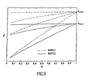
- Figure 3 shows several schematic graphs illustrating the resistance R Ni of a nickel wire as a function of the sensor portion ⁇ subject to overheating for several mean temperatures.
- the device T performs a comparative processing operation to check that the mean temperature corresponding to the nickel resistance R Ni is below a given limiting value R Nimax1 , R Nimax2 since the mean temperature cannot be higher than the ambient temperature. When this is not the case, the device T triggers the transmission of a warning signal indicative of a malfunction of the sensor C.
- the device T also performs a dynamic processing operation by analysing variations in one or more parameters, for example, to indicate overheating or an inconsistency in the measurements.
- the device T compares certain threshold values not to the resistance R NTC of the material 4 and the resistance R Ni of the wire 1 directly, but to differential values of these resistances.
- the device T advantageously determines the sensor portion ⁇ that is subject to overheating and performs a consistency test on the determination thus made. This includes analysing the variations in log(R NTC ) (i.e., the difference between log(R NTC ) at time T1 and log(R NTC ) at time T0) and the variations in the resistance R Ni of the wire 1 (i.e., the difference between R Ni at time T1 and R Ni at time T0).
- the parameters that constitute log(R NTC ) and the resistance R Ni of the wire 1 are in fact parameters which have been shown to vary linearly with temperature (local temperature and ambient temperature, respectively).
- Figure 4 illustrates the values of a ratio of the variations of log(R NTC ) and R Ni for various values of the sensor portion ⁇ subject to overheating. The ratio values are plotted as a function of the measured local temperatures and mean temperatures.
- the ratio of the variations in these two parameters varies with the mean temperature and with the local temperature as a function that depends directly on the sensor portion ⁇ that is subject to overheating.
- the local temperature is more than 100°C above the mean temperature of the sensor C the determined curves are asymptotic curves that depend directly on the value of the sensor portion ⁇ , but not of the temperature. This allows to conclude what portion of the sensor C is overheated, for example, 50% of the sensor C is overheated.
- the asymptotic value taken by the aforementioned ratio has been plotted for various values of ⁇ .
- the device T determines the value of ⁇ that corresponds to the variations in the values of log (R NTC ) and R Ni that the device T measures.
- the device T analyses the consistency of the determined ⁇ value and when the ⁇ value exceeds the [0,1] range transmits a signal indicative of a failure of the sensor C.
- ratios of variations could be used.
- the ratio of differential values of log(R NTC ) and R Ni could be used in the same way, wherein the differential values are calculated on the basis of the values taken by the two parameters log(R NTC ) and R Ni at two different measurement times.
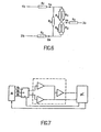
- Figure 6 is a schematic representation of an equivalent circuit diagram of the sensor C including the terminals 1 a, 2a and 3a shown in Figure 1.
- the circuit diagram includes two resistors R 1 and R 2 connected via an intermediate terminal ZA.
- a resistor R f is connected between the terminal ZA and a terminal 3b.
- the resistor R f is equal to the resistance R f of connecting cables that connect the terminals 1 a, 2a of the resistors R 1 and R 2 to terminals 1 b and 2b, respectively.
- a perturbation resistor R p is also shown connected between the terminals 1 a, 2a of the resistors R 1 and R 2 .
- the resistor R 1 corresponds to the resistance R Ni in parallel with R p1
- the resistor R 2 corresponds to the resistance R NTC in parallel with R p2 .
- the various resistances between the terminals 1 b to 3b are measured cyclically using a circuit illustrated in Figure 7.
- the circuit measures successively the resistance between the terminals 1 b and 2b, the resistance between the terminals 1 b and 3b and the resistance between the terminals 2b and 3b.
- the circuit determines in succession, the ratio of the voltages U 1 ⁇ b ⁇ 3 ⁇ b U 2 ⁇ b ⁇ 3 ⁇ b , the ratio of the voltages U 3 ⁇ b ⁇ 2 ⁇ b U 1 ⁇ b ⁇ 2 ⁇ b and the ratio U 2 ⁇ b ⁇ 1 ⁇ b U 3 ⁇ b ⁇ 1 ⁇ b , where U kl denotes the voltage between a terminal k and a terminal I, wherein k and I indicate the terminals 1 b, 2b and 3b.
- the device T of the system comprises a multiplexer M that selects particular terminals of the sensor in order to perform the measurements, and a microprocessor ⁇ C that receives outputs from the multiplexer M.
- the multiplexer M outputs voltages that may be shaped before input to the microprocessor ⁇ C.
- R Ni R P .
- R 1 R P - R 1 R NTC R P .
- R 2 R P - R 2 R 12 R 1 + R 2 .
- R 23 R P + R 1 .
- R 13 R P + R 2 .
- the system of equations is generally not invertible in order to obtain R f .
- the value of R f can be estimated by assuming that R f obeys a symmetrical model.
- the value of R f like the value of R p , is compared with maximum values that demonstrate the existence of fouling at the contacts and therefore indicate a state conducive to potential failures.
- the perturbations in the measurements may also, where appropriate, be corrected accordingly.
- R Ni and R NTC cannot be calculated directly.
- R p and R f as perturbations introduced on the system, it is possible to estimate and put limits on said values of R p and R f , and consequently to detect an abnormal situation.
Abstract
Description
- The present invention relates to a system for detecting fire or overheating.
- A variety of different systems and methods for detecting fire or 10 overheating are known. These systems are often used in engine regions, for example, of an aircraft, ship, helicopter, submarine, space shuttle or industrial plant, and more generally in any sensitive region where the risk of fire or overheating exists, for example, in a hold or bunker, train compartment or boiler.
-
US. Patent No. 5 136 278 describes one type of detector that detects local or average overheating. The detector uses a gas which, when it expands owing to the effect of overheating, trips an electrical contact, thereby indicating that a mean temperature of the detector has exceeded a threshold temperature. Metal oxides with an absorbed gas distributed over the entire length of the detector provide, by a degassing principle, a local indication that the temperature exceeds the threshold temperature. - Another type of detector measures the resistance of a material having a negative thermal coefficient ("NTC"). The material may be implemented as a negative thermal coefficient cable. This type of detector is used for detecting local overheating.
- An example can be provided in
US. A-5 172 099 which describes a system for detecting fire or overheating comprising two sensor materials by means of respective thermistors that have different resistance values, for example based on thermal positive and negative coefficients. Both resistances are measured in a differentially way and are dynamically indicative of the temperature related to an overheating but also to a malfunction of the system. - A gas-type detector requires moving parts to be joined together and has, therefore, a complicated, fragile and expensive construction. An NTC-type detector applies the resistance as the sole criterion and is not very robust in fault situations. It is, therefore, an objective to provide a system for detecting fire or overheating that has improved features with respect to construction and 35 robustness.
- One inventive aspect involves a system for detecting fire or overheating. The system includes a sensor including at least one material having a resistance with a selected temperature coefficient, wherein the resistance of the material is indicative of a temperature. The system includes further a device connected to the sensor to perform measurements on the at least one material, wherein the device is configured to determine at least one parameter from the measurements and to analyze a dynamic behaviour of the at least one parameter to deduce status information including overheating and malfunction of the sensor.
- Another inventive aspect involves a method of detecting fire or overheating. The method performs measurements on at least one material having a resistance with a selected temperature coefficient and included in a sensor that is coupled to a device, wherein the resistance of the material is indicative of a temperature. At least one parameter is determined from the measurements. A dynamic behaviour of the at least one parameter is analyzed to deduce status information including overheating and malfunction of the sensor.
- The system proposed has in particular the advantage of carrying out processing operations that take into account fouling situations or failure situations (a short circuit, open circuit, etc.). It also has the advantage of allowing thermal profiles to be determined in real time.
- These and other aspects, advantages and novel features of the embodiments described herein will become apparent upon reading the following detailed description and upon reference to the accompanying drawings. In the drawings, same elements have the same reference numerals.
- Figure 1 is a schematic representation of one embodiment of a system for detecting fire or overheating;
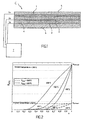
- Figure 2 shows schematic graphs illustrating the resistance of a material with a negative temperature coefficient as a function of temperature and a sensor portion subject to overheating;
- Figure 3 shows schematic graphs illustrating the resistance of a nickel wire as a function of a sensor portion subject to overheating;
- Figure 4 shows graphs as a function of a sensor portion subject to overheating, local temperature and mean temperature;
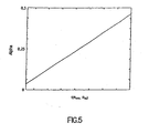
- Figure 5 is a graph illustrating a sensor portion subject to overheating as a function of the graphs shown in Figure 4;
- Figure 6 is a schematic representation of an equivalent circuit diagram of the sensor; and
- Figure 7 is a schematic representation of a measuring and processing device connectable to the sensor.
- Figure 1 shows a schematic illustration of one embodiment of a system for detecting fire or overheating. In one application, the system may be installed in an automobile, train, aircraft or ship, for example, next to or within an engine, passenger or cargo compartment, to detect a fire or overheating. It is contemplated that the system may be installed at any location where the risk of fire or overheating exists, such as at an industrial site, a power generation or transformer station, a data processing or storage room, or an aircraft engine, in particular a jet engine, passenger or cargo compartment.
- The system according to one embodiment comprises a sensor C and a device T connected to the sensor C. The device T measures and processes characteristics obtained from the sensor C. The sensor C comprises a conducting
core 2 extending within asheath 3 that is conducting. For example, thecore 2 may extend along a longitudinal axis of thesheath 3 or along an inside of thesheath 3. Amaterial 4 separates thecore 2 and thesheath 3 and has a negative temperature coefficient. - The sensor C of the illustrated embodiment further comprises a
wire 1 and aninsulating material 5 that separates thewire 1 from thesheath 3. In one embodiment, thewire 1 is made of a material having a positive temperature coefficient ("PTC"), for example, a Nickel (Ni) wire, and is, for example, wound around thesheath 3. Thewire 1, thecore 2 and thesheath 3 are connected to the device T viaterminals external sheath 6. - Variations in a resistance RNi of the
wire 1 are directly proportional to variations in the mean temperature of the sensor C. The variation in a resistance RNTC of thematerial 4 allows local areas of overheating to be detected. For overheating over a given portion of the sensor C, the resistance RNTC of thematerial 4 varies with temperature, i.e., it decreases exponentially. - The device T performs resistance measurements and determines through these measurements the resistance RNi of the
wire 1 and the resistance RNTC of thematerial 4. The resistance values obtained are processed to deduce information regarding possible general or local areas of overheating. Further, the device T processes the resistance values to deduce inconsistencies indicative of a malfunction such as short circuits, open circuits, fouling, etc. - For a particular application and under normal operational conditions, the resistance RNi of the
wire 1 normally takes values which, depending on the envisaged application, lie within a given range. This range depends on the parameters of thewire 1, such as length and diameter. For example, for a length of about 1 m, the range extends between a few ohms (e.g., 20 ohms) and a few hundred ohms (e.g., 200 ohms). The device T therefore compares the measured resistance value of thewire 1 with expected maximum and minimum resistance values for that particular application. When the resistance value of thewire 1 lies outside the given range, the device T triggers the transmission of a signal indicative of a malfunction of the sensor C. - Figure 2 shows several schematic graphs illustrating the resistance RNTC of the
material 4 having a negative temperature coefficient as a function of a sensor portion α subject to overheating. If α = 1, the entire sensor is subject to overheating, and if α = 0.5, half of the sensor length is subject to overheating. The graphs are given for two mean temperatures 250°C and 350°C measured on the basis of the resistance variations of thewire 1, and for various ambient temperatures 100°, 150°, 200° and 300°C. As shown in Figure 2, the graphs representing the resistance RNTC for a given ambient temperature and mean temperature terminate in a maximum limiting value RNTCmax1, RNTCmax2. It is contemplated that a resistance value above the limiting value RNTCmax1, RNTCmax2 is indicative of a defect or perturbation of the sensor C. - A measured resistance RNi of the
wire 1 is indicative of a given overall temperature of the sensor C. For that overall temperature a limiting value RNTCmax1, RNTCmax2 exists at α = 1, i.e., when the entire sensor is subject to overheating. The device T compares the measured resistance RNTC with the limiting value RNTCmax1. RNTCmax2 for the given overall temperature. When the resistance RNTC is greater than this limiting value RNTCmax1. RNTCmax2 the device T triggers the transmission of a signal indicative of a malfunction of the sensor C. - Figure 3 shows several schematic graphs illustrating the resistance RNi of a nickel wire as a function of the sensor portion α subject to overheating for several mean temperatures. Corresponding to each resistance value RNTC1,2 of the
material 4 is a maximum nickel resistance value RNimax1, RNimax2 at α = 1. That is, the resistance RNTC is used to determine a possible value for the resistance RNi, which has to be within a given range for a particular sensor C. For a given value of the resistance RNTC with a negative temperature coefficient, the device T performs a comparative processing operation to check that the mean temperature corresponding to the nickel resistance RNi is below a given limiting value RNimax1, RNimax2 since the mean temperature cannot be higher than the ambient temperature. When this is not the case, the device T triggers the transmission of a warning signal indicative of a malfunction of the sensor C. - The device T also performs a dynamic processing operation by analysing variations in one or more parameters, for example, to indicate overheating or an inconsistency in the measurements. Thus, to determine local overheating or general overheating, the device T compares certain threshold values not to the resistance RNTC of the
material 4 and the resistance RNi of thewire 1 directly, but to differential values of these resistances. - The device T advantageously determines the sensor portion α that is subject to overheating and performs a consistency test on the determination thus made. This includes analysing the variations in log(RNTC) (i.e., the difference between log(RNTC) at time T1 and log(RNTC) at time T0) and the variations in the resistance RNi of the wire 1 (i.e., the difference between RNi at time T1 and RNi at time T0). The parameters that constitute log(RNTC) and the resistance RNi of the
wire 1 are in fact parameters which have been shown to vary linearly with temperature (local temperature and ambient temperature, respectively). Figure 4 illustrates the values of a ratio of the variations of log(RNTC) and RNi for various values of the sensor portion α subject to overheating. The ratio values are plotted as a function of the measured local temperatures and mean temperatures. - The ratio of the variations in these two parameters varies with the mean temperature and with the local temperature as a function that depends directly on the sensor portion α that is subject to overheating. In particular, when the local temperature is more than 100°C above the mean temperature of the sensor C the determined curves are asymptotic curves that depend directly on the value of the sensor portion α, but not of the temperature. This allows to conclude what portion of the sensor C is overheated, for example, 50% of the sensor C is overheated.
- Similarly, in Figure 5, the asymptotic value taken by the aforementioned ratio has been plotted for various values of α. Thus, the device T determines the value of α that corresponds to the variations in the values of log (RNTC) and RNi that the device T measures. The device T analyses the consistency of the determined α value and when the α value exceeds the [0,1] range transmits a signal indicative of a failure of the sensor C.
- Other ratios of variations could be used. In particular, the ratio of differential values of log(RNTC) and RNi could be used in the same way, wherein the differential values are calculated on the basis of the values taken by the two parameters log(RNTC) and RNi at two different measurement times.
- Figure 6 is a schematic representation of an equivalent circuit diagram of the sensor C including the
terminals terminals terminals - A perturbation resistor Rp is also shown connected between the
terminals - The various resistances between the
terminals 1 b to 3b are measured cyclically using a circuit illustrated in Figure 7. The circuit measures successively the resistance between theterminals terminals terminals - Further, in one embodiment, the circuit determines in succession, the ratio of the
voltages 
voltages 
ratio 
terminals - In the illustrated embodiment, the device T of the system comprises a multiplexer M that selects particular terminals of the sensor in order to perform the measurements, and a microprocessor µC that receives outputs from the multiplexer M. In one embodiment, the multiplexer M outputs voltages that may be shaped before input to the microprocessor µC.
- The values of the resistances RNi and RNTC are then determined from the measurements of the resistances between the
terminals 1 b to 3b. Thus:


This system of equations can be solved in order to deduce therefrom the values of RNi, RNTC and Rp. - The system of equations is generally not invertible in order to obtain Rf. The value of Rf can be estimated by assuming that Rf obeys a symmetrical model. In this case, the value of Rf, like the value of Rp, is compared with maximum values that demonstrate the existence of fouling at the contacts and therefore indicate a state conducive to potential failures. The perturbations in the measurements may also, where appropriate, be corrected accordingly.
- In the general case in which Rp and Rf obey an unsymmetrical model, then RNi and RNTC cannot be calculated directly. However, by considering Rp and Rf as perturbations introduced on the system, it is possible to estimate and put limits on said values of Rp and Rf, and consequently to detect an abnormal situation.
Claims (8)
- A system for detecting fire or overheating, comprising:a sensor (C) comprising two materials (1,4) having different selected temperature coefficients, wherein the resistance of the materials (1, 4) is indicative of a temperature,wherein a first material (4) has a first resistance having a negative temperature coefficient, and wherein a second material (1) has a second resistance having a positive temperature coefficient
and
a device (T) connected to the sensor (C) to perform measurements on the first and second materials (1,4), wherein the device (T) is configured to determine at least one parameter from the measurements
the device (T) is configured to analyze a dynamic behaviour of the at least one parameter to deduce status information including overheating and malfunction of the sensor (C),
characterized in that,
the device (T) is configured to analyse variations in the first and second resistances to deduce a sensor portion (α) subject to overheating and
the device (T) is configured to compare the sensor portion (α) to threshold values and to trigger a signal indicative of a malfunction of the sensor (C) when the estimate exceeds one of the threshold values. - The system of claim 1, wherein the device (T) is configured to determine logarithmic variations in one of the first and second resistances.
- The system of any one of Claims 1 to 2, wherein the device (T) is configured to compare measured values of at least one resistance with at least one first limiting value and to trigger a signal indicative of a malfunction when the measured values exceed the first limiting value.
- The system of any one of Claims 1 to 3, wherein the device (T) is configured to compare the second resistance to a second limiting value that depends on the first resistance, and to trigger a signal indicative of a malfunction of the sensor (C) when the second resistance exceeds the second limiting value.
- The system of any one of Claims 1 to 4, wherein the device (T) is configured to compare the first resistance to a third limiting value that depends on the second resistance, and to trigger a signal indicative of a malfunction of the sensor (C) when the first resistance exceeds the third limiting value.
- The system of any one of Claims 1 to 5, wherein the sensor (C) comprises a conducting core (2) that extends within a conducting sheath (3), wherein the first material (4) separates the core (2) and the sheath (3), wherein the second material (1) is a wire that extends on an outside of the sheath (3), and wherein an insulating material (5) separates the wire (1) and the sheath (3), the central core (2), the sheath (3) and the wire (1) each being connected to a terminal.
- The system of Claim 6, wherein the device (T) is configured to measure according to a predetermined sequence a resistance between a terminal of the central core (2) and a terminal of the sheath (3), a resistance between a terminal of the central core (2) and a terminal of the wire (1), and a resistance between a terminal of the sheath (3) and a terminal of the wire (1), the device (T) further configured to use the resistance measurements to deduce an estimate of the resistance of the first material (4) and an estimate of the resistance of the wire (1).
- The system of Claim 7, wherein the device (T) is configured to use the resistance measurements to determine at least one estimate of parasitic resistances (Rf) and to trigger a signal indicative of a malfunction of the sensor (C) when the estimate exceeds a predetermined threshold value for the parasitic resistance.
Applications Claiming Priority (2)
| Application Number | Priority Date | Filing Date | Title |
|---|---|---|---|
| FR0302579 | 2003-03-03 | ||
| FR0302579A FR2852132B1 (en) | 2003-03-03 | 2003-03-03 | FIRE DETECTION OR OVERHEATING SYSTEM |
Publications (2)
| Publication Number | Publication Date |
|---|---|
| EP1455320A1 EP1455320A1 (en) | 2004-09-08 |
| EP1455320B1 true EP1455320B1 (en) | 2007-10-10 |
Family
ID=32799621
Family Applications (1)
| Application Number | Title | Priority Date | Filing Date |
|---|---|---|---|
| EP04004409A Expired - Lifetime EP1455320B1 (en) | 2003-03-03 | 2004-02-26 | Fire or overheating detection system |
Country Status (6)
| Country | Link |
|---|---|
| US (1) | US7098797B2 (en) |
| EP (1) | EP1455320B1 (en) |
| AT (1) | ATE375581T1 (en) |
| DE (1) | DE602004009352T2 (en) |
| ES (1) | ES2294380T3 (en) |
| FR (1) | FR2852132B1 (en) |
Cited By (2)
| Publication number | Priority date | Publication date | Assignee | Title |
|---|---|---|---|---|
| AU2007203071B2 (en) * | 2006-07-07 | 2009-04-02 | Sureland Industrial Fire Safety Limited | An analog line-type temperature sensitive fire detection cable |
| EP3795967B1 (en) * | 2019-09-23 | 2023-04-05 | Kidde Technologies, Inc. | Aircraft temperature sensor |
Families Citing this family (10)
| Publication number | Priority date | Publication date | Assignee | Title |
|---|---|---|---|---|
| DE102006045083A1 (en) * | 2006-09-15 | 2008-03-27 | Bombardier Transportation Gmbh | Rail vehicle with a fire detection device |
| RU2626716C1 (en) * | 2016-06-08 | 2017-07-31 | Акционерное общество "Уфимское научно-производственное предприятие "Молния" | Method for fire or overheat detection, and device for its implementation |
| RU2632765C1 (en) * | 2016-08-16 | 2017-10-09 | Александр Иванович Завадский | Method of fire or overheat detection, and device for its implementation |
| RU2637095C1 (en) * | 2016-08-19 | 2017-11-29 | Акционерное общество "Абрис" | Method of fire or overheat detection, and device for its implementation |
| RU2637094C1 (en) * | 2016-10-25 | 2017-11-29 | Александр Иванович Завадский | Method for detecting fire or overheating with use of duplicated linear thermoresistive sensors and device for its implementation |
| CN106777908B (en) * | 2016-11-28 | 2019-05-03 | 中国人民解放军海军工程大学 | A method of building hot drill process interface, achievement assessment model |
| CN109186786B (en) * | 2018-10-10 | 2020-01-07 | 西安交通大学 | Device and method for monitoring whether electrical contact of electrical equipment is overheated |
| RU2715181C1 (en) * | 2019-04-16 | 2020-02-25 | Александр Иванович Завадский | Method of detecting fire or overheating in aircraft engine compartment and device for its implementation |
| US11092079B2 (en) | 2019-07-18 | 2021-08-17 | Kidde Technologies, Inc. | Support arrangements, fire and overheat detection systems, and methods of making support arrangements for fire and overheat detection systems |
| US11285348B2 (en) | 2019-08-08 | 2022-03-29 | Kidde Technologies, Inc. | Mounting assemblies for fire and overheat detection systems |
Citations (1)
| Publication number | Priority date | Publication date | Assignee | Title |
|---|---|---|---|---|
| US5172099A (en) * | 1990-05-15 | 1992-12-15 | Walter Kidde Aerospace Inc. | Self monitoring fire detection system |
Family Cites Families (7)
| Publication number | Priority date | Publication date | Assignee | Title |
|---|---|---|---|---|
| US3643245A (en) * | 1970-03-11 | 1972-02-15 | Kidde & Co Walter | Discrete heat-detecting system using a thermistor detecting element |
| US4037463A (en) * | 1974-07-10 | 1977-07-26 | Showa Denko Kabushiki Kaisha | Temperature-detecting element |
| JP2996754B2 (en) * | 1991-03-29 | 2000-01-11 | ホーチキ株式会社 | Compensated heat detector |
| US5225811A (en) * | 1992-02-04 | 1993-07-06 | Analog Devices, Inc. | Temperature limit circuit with dual hysteresis |
| GB2276944A (en) * | 1993-04-05 | 1994-10-12 | Central Research Lab Ltd | Excess-temperature detection arrangement |
| JP3205517B2 (en) * | 1996-12-20 | 2001-09-04 | 矢崎総業株式会社 | PTC activation indicator |
| US6288638B1 (en) * | 1999-05-06 | 2001-09-11 | William P. Tanguay | Heat detector having an increased accuracy alarm temperature threshold and improved low temperature testing capabilities |
-
2003
- 2003-03-03 FR FR0302579A patent/FR2852132B1/en not_active Expired - Fee Related
-
2004
- 2004-02-26 DE DE602004009352T patent/DE602004009352T2/en not_active Expired - Lifetime
- 2004-02-26 ES ES04004409T patent/ES2294380T3/en not_active Expired - Lifetime
- 2004-02-26 EP EP04004409A patent/EP1455320B1/en not_active Expired - Lifetime
- 2004-02-26 AT AT04004409T patent/ATE375581T1/en not_active IP Right Cessation
- 2004-03-02 US US10/791,214 patent/US7098797B2/en not_active Expired - Fee Related
Patent Citations (1)
| Publication number | Priority date | Publication date | Assignee | Title |
|---|---|---|---|---|
| US5172099A (en) * | 1990-05-15 | 1992-12-15 | Walter Kidde Aerospace Inc. | Self monitoring fire detection system |
Cited By (2)
| Publication number | Priority date | Publication date | Assignee | Title |
|---|---|---|---|---|
| AU2007203071B2 (en) * | 2006-07-07 | 2009-04-02 | Sureland Industrial Fire Safety Limited | An analog line-type temperature sensitive fire detection cable |
| EP3795967B1 (en) * | 2019-09-23 | 2023-04-05 | Kidde Technologies, Inc. | Aircraft temperature sensor |
Also Published As
| Publication number | Publication date |
|---|---|
| FR2852132B1 (en) | 2007-06-22 |
| ES2294380T3 (en) | 2008-04-01 |
| US20040233062A1 (en) | 2004-11-25 |
| FR2852132A1 (en) | 2004-09-10 |
| DE602004009352T2 (en) | 2008-07-17 |
| US7098797B2 (en) | 2006-08-29 |
| EP1455320A1 (en) | 2004-09-08 |
| DE602004009352D1 (en) | 2007-11-22 |
| ATE375581T1 (en) | 2007-10-15 |
Similar Documents
| Publication | Publication Date | Title |
|---|---|---|
| EP1455320B1 (en) | Fire or overheating detection system | |
| US7650211B2 (en) | Method and apparatus to monitor ambient sensing devices | |
| US11329436B2 (en) | Electrical contact element for a plug connector, plug connector and method for monitoring an electrical current flow | |
| EP2609408B1 (en) | Process fluid temperature measurement | |
| CN107271839B (en) | Method and control device for monitoring an on-board electrical system of a vehicle | |
| US7445383B2 (en) | Method and device for diagnosing an external temperature sensor | |
| EP2026040B1 (en) | Sensor arrangement | |
| CN100454347C (en) | Data fusion alarm system and method for linear fire detector | |
| JPH06211102A (en) | Electronic device and method of inspecting said device | |
| US7276901B2 (en) | Method for shunt detection in sensors | |
| CN107545692B (en) | Unrecoverable cable type linear temperature-sensing fire disaster detector | |
| EP3548855B1 (en) | Shorted thermocouple diagnostic | |
| US5172099A (en) | Self monitoring fire detection system | |
| EP1396729B1 (en) | Method of diagnosing a motor vehicle battery | |
| US20170363481A1 (en) | Fault Detection Apparatus | |
| CA2957777C (en) | Pneumatic fire detectors | |
| CN112629709B (en) | Temperature sensor fault detection method, detection device and electric vehicle controller | |
| JP4824504B2 (en) | Temperature sensor control device | |
| US11676477B2 (en) | Fire alarm system | |
| RU2626716C1 (en) | Method for fire or overheat detection, and device for its implementation | |
| KR20190088017A (en) | Monitoring apparatus for a cooling apparatus | |
| CN220809130U (en) | Safety monitoring device of battery system, battery system and vehicle | |
| EP4096349A1 (en) | Positive temperature coefficient resistor heater assembly health monitoring | |
| EP4369003A1 (en) | Battery monitoring method and device | |
| US10578636B2 (en) | Electronic device for detecting an air flow |
Legal Events
| Date | Code | Title | Description |
|---|---|---|---|
| PUAI | Public reference made under article 153(3) epc to a published international application that has entered the european phase |
Free format text: ORIGINAL CODE: 0009012 |
|
| AK | Designated contracting states |
Kind code of ref document: A1 Designated state(s): AT BE BG CH CY CZ DE DK EE ES FI FR GB GR HU IE IT LI LU MC NL PT RO SE SI SK TR |
|
| AX | Request for extension of the european patent |
Extension state: AL LT LV MK |
|
| RIN1 | Information on inventor provided before grant (corrected) |
Inventor name: COLOMBIER, JEAN PAUL Inventor name: MANGON, PHILIPPE Inventor name: CHAHROUR, WAEL |
|
| 17P | Request for examination filed |
Effective date: 20050110 |
|
| AKX | Designation fees paid |
Designated state(s): AT BE BG CH CY CZ DE DK EE ES FI FR GB GR HU IE IT LI LU MC NL PT RO SE SI SK TR |
|
| 17Q | First examination report despatched |
Effective date: 20060831 |
|
| GRAP | Despatch of communication of intention to grant a patent |
Free format text: ORIGINAL CODE: EPIDOSNIGR1 |
|
| GRAS | Grant fee paid |
Free format text: ORIGINAL CODE: EPIDOSNIGR3 |
|
| GRAA | (expected) grant |
Free format text: ORIGINAL CODE: 0009210 |
|
| AK | Designated contracting states |
Kind code of ref document: B1 Designated state(s): AT BE BG CH CY CZ DE DK EE ES FI FR GB GR HU IE IT LI LU MC NL PT RO SE SI SK TR |
|
| REG | Reference to a national code |
Ref country code: GB Ref legal event code: FG4D |
|
| REG | Reference to a national code |
Ref country code: CH Ref legal event code: EP |
|
| REG | Reference to a national code |
Ref country code: IE Ref legal event code: FG4D |
|
| REF | Corresponds to: |
Ref document number: 602004009352 Country of ref document: DE Date of ref document: 20071122 Kind code of ref document: P |
|
| ET | Fr: translation filed | ||
| REG | Reference to a national code |
Ref country code: CH Ref legal event code: AEN Free format text: DAS PATENT IST AUF GRUND DES WEITERBEHANDLUNGSANTRAGS VOM 01.02.2008 REAKTIVIERT WORDEN. Ref country code: CH Ref legal event code: PL |
|
| REG | Reference to a national code |
Ref country code: ES Ref legal event code: FG2A Ref document number: 2294380 Country of ref document: ES Kind code of ref document: T3 |
|
| PG25 | Lapsed in a contracting state [announced via postgrant information from national office to epo] |
Ref country code: SE Free format text: LAPSE BECAUSE OF FAILURE TO SUBMIT A TRANSLATION OF THE DESCRIPTION OR TO PAY THE FEE WITHIN THE PRESCRIBED TIME-LIMIT Effective date: 20080110 |
|
| PG25 | Lapsed in a contracting state [announced via postgrant information from national office to epo] |
Ref country code: PT Free format text: LAPSE BECAUSE OF FAILURE TO SUBMIT A TRANSLATION OF THE DESCRIPTION OR TO PAY THE FEE WITHIN THE PRESCRIBED TIME-LIMIT Effective date: 20080310 Ref country code: BG Free format text: LAPSE BECAUSE OF FAILURE TO SUBMIT A TRANSLATION OF THE DESCRIPTION OR TO PAY THE FEE WITHIN THE PRESCRIBED TIME-LIMIT Effective date: 20080110 |
|
| PG25 | Lapsed in a contracting state [announced via postgrant information from national office to epo] |
Ref country code: AT Free format text: LAPSE BECAUSE OF FAILURE TO SUBMIT A TRANSLATION OF THE DESCRIPTION OR TO PAY THE FEE WITHIN THE PRESCRIBED TIME-LIMIT Effective date: 20071010 |
|
| PG25 | Lapsed in a contracting state [announced via postgrant information from national office to epo] |
Ref country code: CZ Free format text: LAPSE BECAUSE OF FAILURE TO SUBMIT A TRANSLATION OF THE DESCRIPTION OR TO PAY THE FEE WITHIN THE PRESCRIBED TIME-LIMIT Effective date: 20071010 Ref country code: DK Free format text: LAPSE BECAUSE OF FAILURE TO SUBMIT A TRANSLATION OF THE DESCRIPTION OR TO PAY THE FEE WITHIN THE PRESCRIBED TIME-LIMIT Effective date: 20071010 |
|
| PGFP | Annual fee paid to national office [announced via postgrant information from national office to epo] |
Ref country code: FR Payment date: 20080214 Year of fee payment: 5 |
|
| PLBE | No opposition filed within time limit |
Free format text: ORIGINAL CODE: 0009261 |
|
| STAA | Information on the status of an ep patent application or granted ep patent |
Free format text: STATUS: NO OPPOSITION FILED WITHIN TIME LIMIT |
|
| PG25 | Lapsed in a contracting state [announced via postgrant information from national office to epo] |
Ref country code: SK Free format text: LAPSE BECAUSE OF FAILURE TO SUBMIT A TRANSLATION OF THE DESCRIPTION OR TO PAY THE FEE WITHIN THE PRESCRIBED TIME-LIMIT Effective date: 20071010 Ref country code: RO Free format text: LAPSE BECAUSE OF FAILURE TO SUBMIT A TRANSLATION OF THE DESCRIPTION OR TO PAY THE FEE WITHIN THE PRESCRIBED TIME-LIMIT Effective date: 20071010 |
|
| 26N | No opposition filed |
Effective date: 20080711 |
|
| REG | Reference to a national code |
Ref country code: CH Ref legal event code: PUE Owner name: SIEMENS SCHWEIZ AG Free format text: CERBERUS S.A.S.#ZI-617, RUE FOURNY-BP20#78531 BUC CEDEX (FR) -TRANSFER TO- SIEMENS SCHWEIZ AG#ALBISRIEDERSTRASSE 245#8047 ZUERICH (CH) |
|
| PG25 | Lapsed in a contracting state [announced via postgrant information from national office to epo] |
Ref country code: MC Free format text: LAPSE BECAUSE OF NON-PAYMENT OF DUE FEES Effective date: 20080228 |
|
| REG | Reference to a national code |
Ref country code: GB Ref legal event code: 732E |
|
| PG25 | Lapsed in a contracting state [announced via postgrant information from national office to epo] |
Ref country code: IE Free format text: LAPSE BECAUSE OF NON-PAYMENT OF DUE FEES Effective date: 20080226 Ref country code: GR Free format text: LAPSE BECAUSE OF FAILURE TO SUBMIT A TRANSLATION OF THE DESCRIPTION OR TO PAY THE FEE WITHIN THE PRESCRIBED TIME-LIMIT Effective date: 20080111 Ref country code: EE Free format text: LAPSE BECAUSE OF FAILURE TO SUBMIT A TRANSLATION OF THE DESCRIPTION OR TO PAY THE FEE WITHIN THE PRESCRIBED TIME-LIMIT Effective date: 20071010 |
|
| PG25 | Lapsed in a contracting state [announced via postgrant information from national office to epo] |
Ref country code: FI Free format text: LAPSE BECAUSE OF FAILURE TO SUBMIT A TRANSLATION OF THE DESCRIPTION OR TO PAY THE FEE WITHIN THE PRESCRIBED TIME-LIMIT Effective date: 20071010 |
|
| REG | Reference to a national code |
Ref country code: CH Ref legal event code: PCOW Free format text: SIEMENS SCHWEIZ AG;FREILAGERSTRASSE 40;8047 ZUERICH (CH) |
|
| REG | Reference to a national code |
Ref country code: FR Ref legal event code: TP |
|
| NLS | Nl: assignments of ep-patents |
Owner name: SIEMENS SCHWEIZ AG Effective date: 20090327 |
|
| PG25 | Lapsed in a contracting state [announced via postgrant information from national office to epo] |
Ref country code: SI Free format text: LAPSE BECAUSE OF FAILURE TO SUBMIT A TRANSLATION OF THE DESCRIPTION OR TO PAY THE FEE WITHIN THE PRESCRIBED TIME-LIMIT Effective date: 20071010 |
|
| REG | Reference to a national code |
Ref country code: CH Ref legal event code: PUE Owner name: SIEMENS AKTIENGESELLSCHAFT Free format text: SIEMENS SCHWEIZ AG#FREILAGERSTRASSE 40#8047 ZUERICH (CH) -TRANSFER TO- SIEMENS AKTIENGESELLSCHAFT#WITTELSBACHERPLATZ 2#80333 MUENCHEN (DE) Ref country code: CH Ref legal event code: NV Representative=s name: SIEMENS SCHWEIZ AG |
|
| PG25 | Lapsed in a contracting state [announced via postgrant information from national office to epo] |
Ref country code: CY Free format text: LAPSE BECAUSE OF FAILURE TO SUBMIT A TRANSLATION OF THE DESCRIPTION OR TO PAY THE FEE WITHIN THE PRESCRIBED TIME-LIMIT Effective date: 20071010 |
|
| REG | Reference to a national code |
Ref country code: GB Ref legal event code: 732E Free format text: REGISTERED BETWEEN 20090716 AND 20090722 |
|
| NLS | Nl: assignments of ep-patents |
Owner name: SIEMENS AKTIENGESELLSCHAFT Effective date: 20090716 |
|
| REG | Reference to a national code |
Ref country code: FR Ref legal event code: ST Effective date: 20091030 |
|
| REG | Reference to a national code |
Ref country code: ES Ref legal event code: PC2A |
|
| PG25 | Lapsed in a contracting state [announced via postgrant information from national office to epo] |
Ref country code: FR Free format text: LAPSE BECAUSE OF NON-PAYMENT OF DUE FEES Effective date: 20090302 |
|
| PGFP | Annual fee paid to national office [announced via postgrant information from national office to epo] |
Ref country code: BE Payment date: 20100217 Year of fee payment: 7 |
|
| PG25 | Lapsed in a contracting state [announced via postgrant information from national office to epo] |
Ref country code: HU Free format text: LAPSE BECAUSE OF FAILURE TO SUBMIT A TRANSLATION OF THE DESCRIPTION OR TO PAY THE FEE WITHIN THE PRESCRIBED TIME-LIMIT Effective date: 20080411 Ref country code: LU Free format text: LAPSE BECAUSE OF NON-PAYMENT OF DUE FEES Effective date: 20080226 |
|
| PG25 | Lapsed in a contracting state [announced via postgrant information from national office to epo] |
Ref country code: TR Free format text: LAPSE BECAUSE OF FAILURE TO SUBMIT A TRANSLATION OF THE DESCRIPTION OR TO PAY THE FEE WITHIN THE PRESCRIBED TIME-LIMIT Effective date: 20071010 |
|
| PG25 | Lapsed in a contracting state [announced via postgrant information from national office to epo] |
Ref country code: IT Free format text: LAPSE BECAUSE OF NON-PAYMENT OF DUE FEES Effective date: 20100226 |
|
| BERE | Be: lapsed |
Owner name: SIEMENS A.G. Effective date: 20110228 |
|
| PG25 | Lapsed in a contracting state [announced via postgrant information from national office to epo] |
Ref country code: BE Free format text: LAPSE BECAUSE OF NON-PAYMENT OF DUE FEES Effective date: 20110228 |
|
| PGFP | Annual fee paid to national office [announced via postgrant information from national office to epo] |
Ref country code: NL Payment date: 20140204 Year of fee payment: 11 |
|
| PGFP | Annual fee paid to national office [announced via postgrant information from national office to epo] |
Ref country code: ES Payment date: 20140324 Year of fee payment: 11 Ref country code: IT Payment date: 20140227 Year of fee payment: 11 |
|
| PGFP | Annual fee paid to national office [announced via postgrant information from national office to epo] |
Ref country code: GB Payment date: 20140210 Year of fee payment: 11 |
|
| PGFP | Annual fee paid to national office [announced via postgrant information from national office to epo] |
Ref country code: DE Payment date: 20140417 Year of fee payment: 11 Ref country code: CH Payment date: 20140508 Year of fee payment: 11 |
|
| REG | Reference to a national code |
Ref country code: CH Ref legal event code: PUE Owner name: SIEMENS SCHWEIZ AG, CH Free format text: FORMER OWNER: SIEMENS AKTIENGESELLSCHAFT, DE |
|
| REG | Reference to a national code |
Ref country code: GB Ref legal event code: 732E Free format text: REGISTERED BETWEEN 20150220 AND 20150225 |
|
| REG | Reference to a national code |
Ref country code: DE Ref legal event code: R082 Ref document number: 602004009352 Country of ref document: DE Representative=s name: MAIER, DANIEL, DIPL.-ING. UNIV., DE |
|
| REG | Reference to a national code |
Ref country code: DE Ref legal event code: R082 Ref document number: 602004009352 Country of ref document: DE Representative=s name: MAIER, DANIEL, DIPL.-ING. UNIV., DE Effective date: 20150407 Ref country code: DE Ref legal event code: R081 Ref document number: 602004009352 Country of ref document: DE Owner name: SIEMENS SCHWEIZ AG, CH Free format text: FORMER OWNER: SIEMENS AKTIENGESELLSCHAFT, 80333 MUENCHEN, DE Effective date: 20150407 |
|
| REG | Reference to a national code |
Ref country code: DE Ref legal event code: R119 Ref document number: 602004009352 Country of ref document: DE |
|
| REG | Reference to a national code |
Ref country code: NL Ref legal event code: V1 Effective date: 20150901 |
|
| PG25 | Lapsed in a contracting state [announced via postgrant information from national office to epo] |
Ref country code: NL Free format text: LAPSE BECAUSE OF NON-PAYMENT OF DUE FEES Effective date: 20150901 |
|
| REG | Reference to a national code |
Ref country code: CH Ref legal event code: PL |
|
| GBPC | Gb: european patent ceased through non-payment of renewal fee |
Effective date: 20150226 |
|
| PG25 | Lapsed in a contracting state [announced via postgrant information from national office to epo] |
Ref country code: CH Free format text: LAPSE BECAUSE OF NON-PAYMENT OF DUE FEES Effective date: 20150228 Ref country code: LI Free format text: LAPSE BECAUSE OF NON-PAYMENT OF DUE FEES Effective date: 20150228 |
|
| PG25 | Lapsed in a contracting state [announced via postgrant information from national office to epo] |
Ref country code: IT Free format text: LAPSE BECAUSE OF NON-PAYMENT OF DUE FEES Effective date: 20150226 |
|
| PG25 | Lapsed in a contracting state [announced via postgrant information from national office to epo] |
Ref country code: DE Free format text: LAPSE BECAUSE OF NON-PAYMENT OF DUE FEES Effective date: 20150901 Ref country code: GB Free format text: LAPSE BECAUSE OF NON-PAYMENT OF DUE FEES Effective date: 20150226 |
|
| REG | Reference to a national code |
Ref country code: ES Ref legal event code: FD2A Effective date: 20160901 |
|
| PG25 | Lapsed in a contracting state [announced via postgrant information from national office to epo] |
Ref country code: ES Free format text: LAPSE BECAUSE OF NON-PAYMENT OF DUE FEES Effective date: 20150227 |