EP1455185A1 - Liquid chromatograph mass spectrometer - Google Patents
Liquid chromatograph mass spectrometer Download PDFInfo
- Publication number
- EP1455185A1 EP1455185A1 EP04003527A EP04003527A EP1455185A1 EP 1455185 A1 EP1455185 A1 EP 1455185A1 EP 04003527 A EP04003527 A EP 04003527A EP 04003527 A EP04003527 A EP 04003527A EP 1455185 A1 EP1455185 A1 EP 1455185A1
- Authority
- EP
- European Patent Office
- Prior art keywords
- column
- separation
- separation column
- columns
- mass spectrometer
- Prior art date
- Legal status (The legal status is an assumption and is not a legal conclusion. Google has not performed a legal analysis and makes no representation as to the accuracy of the status listed.)
- Granted
Links
Images


Classifications
-
- G—PHYSICS
- G01—MEASURING; TESTING
- G01N—INVESTIGATING OR ANALYSING MATERIALS BY DETERMINING THEIR CHEMICAL OR PHYSICAL PROPERTIES
- G01N30/00—Investigating or analysing materials by separation into components using adsorption, absorption or similar phenomena or using ion-exchange, e.g. chromatography or field flow fractionation
- G01N30/02—Column chromatography
- G01N30/26—Conditioning of the fluid carrier; Flow patterns
- G01N30/38—Flow patterns
- G01N30/46—Flow patterns using more than one column
- G01N30/461—Flow patterns using more than one column with serial coupling of separation columns
- G01N30/463—Flow patterns using more than one column with serial coupling of separation columns for multidimensional chromatography
-
- G—PHYSICS
- G01—MEASURING; TESTING
- G01N—INVESTIGATING OR ANALYSING MATERIALS BY DETERMINING THEIR CHEMICAL OR PHYSICAL PROPERTIES
- G01N30/00—Investigating or analysing materials by separation into components using adsorption, absorption or similar phenomena or using ion-exchange, e.g. chromatography or field flow fractionation
- G01N30/02—Column chromatography
- G01N2030/022—Column chromatography characterised by the kind of separation mechanism
- G01N2030/027—Liquid chromatography
-
- G—PHYSICS
- G01—MEASURING; TESTING
- G01N—INVESTIGATING OR ANALYSING MATERIALS BY DETERMINING THEIR CHEMICAL OR PHYSICAL PROPERTIES
- G01N30/00—Investigating or analysing materials by separation into components using adsorption, absorption or similar phenomena or using ion-exchange, e.g. chromatography or field flow fractionation
- G01N30/02—Column chromatography
- G01N30/04—Preparation or injection of sample to be analysed
- G01N30/06—Preparation
- G01N30/12—Preparation by evaporation
- G01N2030/121—Preparation by evaporation cooling; cold traps
-
- G—PHYSICS
- G01—MEASURING; TESTING
- G01N—INVESTIGATING OR ANALYSING MATERIALS BY DETERMINING THEIR CHEMICAL OR PHYSICAL PROPERTIES
- G01N30/00—Investigating or analysing materials by separation into components using adsorption, absorption or similar phenomena or using ion-exchange, e.g. chromatography or field flow fractionation
- G01N30/02—Column chromatography
- G01N30/84—Preparation of the fraction to be distributed
- G01N2030/8411—Intermediate storage of effluent, including condensation on surface
-
- G—PHYSICS
- G01—MEASURING; TESTING
- G01N—INVESTIGATING OR ANALYSING MATERIALS BY DETERMINING THEIR CHEMICAL OR PHYSICAL PROPERTIES
- G01N30/00—Investigating or analysing materials by separation into components using adsorption, absorption or similar phenomena or using ion-exchange, e.g. chromatography or field flow fractionation
- G01N30/02—Column chromatography
- G01N30/26—Conditioning of the fluid carrier; Flow patterns
- G01N30/38—Flow patterns
- G01N30/46—Flow patterns using more than one column
- G01N30/468—Flow patterns using more than one column involving switching between different column configurations
-
- G—PHYSICS
- G01—MEASURING; TESTING
- G01N—INVESTIGATING OR ANALYSING MATERIALS BY DETERMINING THEIR CHEMICAL OR PHYSICAL PROPERTIES
- G01N30/00—Investigating or analysing materials by separation into components using adsorption, absorption or similar phenomena or using ion-exchange, e.g. chromatography or field flow fractionation
- G01N30/02—Column chromatography
- G01N30/62—Detectors specially adapted therefor
- G01N30/72—Mass spectrometers
- G01N30/7233—Mass spectrometers interfaced to liquid or supercritical fluid chromatograph
Definitions
- the present invention relates to a liquid chromatograph mass spectrometer, and more particularly to a multidimensional liquid chromatograph mass spectrometer having a plurality of separation columns.
- Liquid chromatograph mass spectrometers have been used to analyze sample solutions containing a plurality of components.
- a liquid chromatograph mass spectrometer comprises: a liquid chromatograph which passes a sample through its separation column and thereby separates the components of the sample from one another by utilizing the fact that each component varies in its interaction with the column; and a mass spectrometer which ionizes the separated components one after another and detects the generated ions.
- a multidimensional liquid chromatograph mass spectrometer For analysis of a sample containing many species of components, a multidimensional liquid chromatograph mass spectrometer is used which includes a multidimensional liquid chromatograph having therein a plurality of separation columns connected in series to further separate the components from one another.
- Japanese Patent Laid-Open No. 62-255865 describes a liquid chromatograph which does not employ series-connected separation columns but in which a sample concentration column, a reaction column, and a separation column are connected in series.
- the technique described in Japanese Patent Laid-Open No. 62-255865 supplies an eluent to a separation column while supplying a sample solution to a concentration column to concentrate it.
- the flow path switching valve is switched so as to supply a solution for desorption to the separation column through the concentration column and a reaction column.
- Multidimensional liquid chromatograph mass spectrometers employ a plurality of columns using different separation principles.
- Electrolyte solution is not suitable as a solution introduced into a mass spectrometer.
- electrolyte solution cannot be introduced into mass spectrometers.
- each of the plurality of separation columns takes a certain time to complete each separation operation. Therefore, the first column must stop its current separation operation until the second column connected in series to the first column completes its separation operation, making it impossible to continuously supply eluent from the first column to the second column.
- a fraction of eluted components including a target component(s) must be taken from the components eluted from the first separation column and introduced into the second column.
- the time required for the second separation column to complete an entire separation operation is longer than when the eluent is not processed in fractions, since the time increases with the number of samples (fractions) taken from the eluent from the first separation column.
- a biological sample must be analyzed in a short time. Therefore, the above method in which the eluent from the first separation column is processed in fractions cannot be used for biological samples.
- the present invention relates to multidimensional liquid chromatograph mass spectrometers having a plurality of separation columns therein.
- An object of the present invention is to provide a liquid chromatograph mass spectrometer capable of performing quick detection without reducing the separation performance of each separation column and the detection sensitivity of the mass spectrometer.
- one aspect of the present invention provides a liquid chromatograph mass spectrometer comprising: a pump; a sample injector; a plurality of separation columns, including a first separation column and a second separation column; and mass spectrometer; wherein the liquid chromatograph mass spectrometer further comprises: a plurality of trap columns for retaining a sample component separated by the first separation column; a first switching valve for switching between one of the plurality of trap columns and another one of the plurality of trap columns at regular time intervals in such a way that when the one of the plurality of trap columns is connected to the first separation column, the another one of the plurality of trap columns is connected to the pump, and vice versa; and a second switching valve for, when a trap column is connected to the pump, further connecting the trap column to the second separation column after connecting the trap column to solution discharging means during a predetermined initial time period, the second separation column being connected with the mass spectrometer and capable of separating the sample component in a shorter time than the first
- the above liquid chromatograph mass spectrometer further comprises: a detector for detecting a chromatograph of a sample, the detector being disposed between the first separation column and the plurality of trap columns.
- the second separation column is a monolithic column capable of performing separation at high speed.
- a liquid chromatograph mass spectrometer comprising: a pump; a sample injector; a plurality of separation columns, including a first separation column and a plurality of second separation columns; and mass spectrometer; wherein the plurality of second separation columns further separate a sample component separated by the first separation column, the plurality of second separation columns being capable of separating the sample component in a shorter time than the first separation column; and wherein the liquid chromatograph mass spectrometer further comprises: a first switching valve for switching between one of the plurality of second separation columns and another one of the plurality of second separation columns at regular time intervals in such a way that when the one of the plurality of second separation columns is connected to the first separation column, the another one of the plurality of second separation columns is connected to the pump, and vice versa; and a second switching valve for, when a second separation column is connected to the pump, further connecting the second separation column to the mass spectrometer after connecting the second separation column to solution dischar
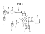
- Fig. 1 is a schematic diagram showing the configuration of a liquid chromatograph mass spectrometer according to a first embodiment of the present invention.
- a pump 1 supplies eluents 2 and 3 to a sample injector 4 at a constant flow rate while changing their composition ratio.
- the sample injector 4 injects a sample into the flow path together with the eluents supplied from the pump 1.
- the components contained in the injected sample are fed to a separation column 5 and eluted in the order of increasing interaction with the separation column 5.
- Each component eluted from the separation column 5 is detected by an ultraviolet-visible absorbance detector 6 and then introduced to a 10-port switching valve 7.
- the 10-port switching valve 7 is connected with two trap columns 8 and 9, and switches the flow paths such that the components eluted from the separation column 5 are supplied to the trap column 8 and the trap column 9 alternately at regular time intervals.
- Fig. 2 shows the flow paths formed by the 10-port switching valve 7.
- the 10-port switching valve 7 can switch between two flow path formations, as shown in Figs. 2A and 2B.
- trap column 9 is currently connected between a pump 11 and a switching valve 13 shown in Fig. 1 through flow paths.
- the 10-port switching valve 7 switches back to the connection state shown in Fig. 2B so that the trap column 8 is connected between the pump 11 and the switching valve 13 through flow paths. Then, the components and the eluents held in the trap column 8 are eluted by an eluent 12 introduced by the pump 11 at a constant flow rate.
- the flow path switching valve 13 is switched from the waste solution bottle 14 to a high-speed separation column 15 so that the components eluted from the trap column 8 are fed to the high-speed separation column 15.
- the trap column 9 is connected to the separation column 5 through the ultraviolet-visible absorbance detector 6 and further connected to the path for discharging waste solution into the waste solution bottle 10.
- the sample continues to be supplied to the separation column 5 without interruption.
- the sample is fed to the trap column 9 through the ultraviolet-visible absorbance detector 6.
- the components of the sample are held in the trap column 9, while a considerable portion of each eluent is discharged into the waste solution bottle 14.
- the components which have been fed from the trap column 8 to the high-speed separation column 15 are further separated and eluted in the order of increasing interaction with the high-speed separation column 15.
- the eluted components are introduced to the mass spectrometer 16, which provides information on their mass numbers.
- the high-speed separation column 15 takes less time to complete component separation than the separation column 5
- the high-speed separation column 15 completes the component separation in a time shorter than the component trapping time of each of the trap columns 8 and 9.
- the 10-port switching value 7 switches between the connection state shown in Fig. 2A and that shown in Fig. 2B at regular time intervals.
- Fig. 3 shows analysis results obtained when a measurement was made on a sample peptide compound using a cation exchange column and a monolithic column as the separation column 5 and the high-speed separation column 15, respectively, in the first embodiment shown in Fig. 1.
- monolithic columns use cylindrical rods as their packing material, instead of spherical particles which have used by conventional columns, and therefore can perform component separation in a short time, as compared with conventional columns filled with spherical particles.
- Fig. 4 shows chromatograms obtained when the same components are analyzed using an ODS column containing spherical particles and a monolithic column using a cylindrical rod of silica as its carrier.
- Fig. 4A shows the chromatogram obtained using the ODS column
- Fig. 4B shows that obtained using the monolithic column.
- the ODS column took approximately 25 minutes to separate all components whereas the monolithic column took only 5 minutes or less.
- Fig. 3A shows a UV chromatogram obtained by the ultraviolet-visible absorbance detector 6.
- the UV chromatogram shows the peak of each peptide component separated by the cation exchange column.
- Fig. 3B shows a total ion chromatogram of components, obtained by the mass spectrometer 16. The components were eluted during the 2 minute time period between the two time points corresponding to the retention time 18 minutes and the retention time 20 minutes. The components were then fed to the trap column 8 and separated in the monolithic column 15 before they were mass analyzed.
- the components are detected as a single peak in the 2 minute time period between the two time points corresponding to the retention times 18 minutes and 20 minutes.
- the total ion chromatogram shown in Fig. 3B on the other hand, they are detected as three component peaks 1 ⁇ , 2 ⁇ , and 3 ⁇ separated by the monolithic column.
- Fig. 3C shows a mass spectrum of the peak 2 ⁇ detected in the total ion chromatogram shown in Fig. 3B.
- the cation exchange column uses the eluents 2 and 3 as buffer solutions to separate components. However, introducing the buffer solutions into the mass spectrometer 16 as they are decreases the component detection sensitivity.
- the first embodiment of the present invention uses the trap columns 8 and 9 to wash away the eluents 2 and 3 (buffer solutions) with the eluent 12 containing no buffer solution, preventing the buffer solutions from entering the mass spectrometer 16.
- the second separation column (monolithic column 15) can complete the component separation in a time shorter than the time required for the separation by the separation column 5, that is, the time required for the trap column to trap the components, making it possible to continuously supply the sample to the first separation column 5.
- the separation completion time of the second separation column is delayed by the time required to discharge the buffer solutions retained within the trap column 8 or 9. This means that the sample supply to the first separation column must be halted during that time, making it impossible to continuously supply the sample to the first separation column 5.
- the first embodiment of the present invention can provide a liquid chromatograph mass spectrometer capable of quickly detecting components without adversely affecting the separation performance of each of the plurality of separation columns and the detection sensitivity of the mass spectrometer.
- a high-speed separation column represented by the monolithic column, is a separation column capable of separating components in a shorter time than the first separation column.
- Fig. 5 is a schematic diagram showing the configuration of a liquid chromatograph mass spectrometer according to a second embodiment of the present invention.
- the second embodiment is different from the first embodiment in that the second embodiment employs high-speed separation columns 17 and 18 instead of the trap columns 8 and 9 and has omitted the separation column 15.
- the other components are same as those of the first embodiment.
- the 10-port switching valve 7 switches the flow paths at regular time intervals so as to feed each component to either the high-speed separation column 17 or 18.
- Fig. 6 shows the flow paths formed by the 10-port switching valve 7.
- the 10-port switching valve 7 can switch between two flow path formations, as shown in Figs. 6A and 6B.
- the components which have passed through the ultraviolet-visible absorbance detector 6 are held in the high-speed separation column 17.
- a considerable portion of each eluent, which is not held in the high-speed separation column 17, is eluted from the high-speed separation column 17 and discharged into the waste solution bottle 10.
- the 10-port switching valve 7 switches to the state shown in Fig. 6B.
- the eluents 2 and 3 present within the high-speed separation column 17 are eluted from the high-speed separation column 17 by the action of the eluent 12 and discharged into the waste solution bottle 14 by way of the flow path switching valve 13.
- the switching valve 13 is switched from the waste solution bottle 14 to the mass spectrometer 16 side, so that each component held in the high-speed separation column 17 is separated and eluted in the order of increasing interaction with the high-speed separation column 17 by the action of the eluent 12 supplied by the pump 11 at a constant flow rate. Each component is then introduced into the mass spectrometer 16, which provides information on its mass number.
- the second embodiment of the present invention can produce the same effect as that of the first embodiment.
- the present invention provides multidimensional liquid chromatograph mass spectrometers having a plurality of separation columns.
- the present invention can provide a liquid chromatograph mass spectrometer capable of quickly detecting components without adversely affecting the separation performance of each separation column and the detection sensitivity of the mass spectrometer.
Landscapes
- Physics & Mathematics (AREA)
- Health & Medical Sciences (AREA)
- Life Sciences & Earth Sciences (AREA)
- Chemical & Material Sciences (AREA)
- Analytical Chemistry (AREA)
- Biochemistry (AREA)
- General Health & Medical Sciences (AREA)
- General Physics & Mathematics (AREA)
- Immunology (AREA)
- Pathology (AREA)
- Other Investigation Or Analysis Of Materials By Electrical Means (AREA)
Abstract
Description
Claims (4)
- A liquid chromatography mass spectrometer comprising:wherein said liquid chromatography mass spectrometer further comprises:a pump (11);a sample injector (4);a plurality of separation columns, including a first separation column (5) and a second separation column (15); anda mass spectrometer (16);a plurality of trap columns (8, 9) for retaining a sample component separated by said first separation column (5);a first switching valve (7) for switching between one of said plurality of trap columns (8, 9) and another one of said plurality of trap columns (8, 9) at regular time intervals in such a way that when said one of said plurality of trap columns is connected to said first separation column (5), said another one of said plurality of trap columns is connected to said pump (11), and vice versa; anda second switching valve (13) for, when a trap column (8, 9) is connected to said pump (11), further connecting said trap column to said second separation column (15) after connecting said trap column to solution discharging means (14) during a predetermined initial time period, said second separation column (15) being connected to said mass spectrometer (16) and capable of separating said sample component in a shorter time than said first separation column (5).
- The liquid chromatography mass spectrometer as claimed in claim 1, further comprising:a detector (6) for detecting a chromatogram of a sample, said detector being disposed between said first separation column (5) and said plurality of trap columns (8, 9).
- The liquid chromatography mass spectrometer as claimed in claim 1, wherein said second separation column (15) is a monolithic column capable of performing separation at high speed.
- A liquid chromatography mass spectrometer comprising:wherein said plurality of second separation columns (17, 18) further separate a sample component separated by said first separation column (5), said plurality of second separation columns being capable of separating said sample component in a shorter time than said first separation column; anda pump (11);a sample injector (4);a plurality of separation columns including a first separation column (5) and a plurality of second separation columns (17, 18); anda mass spectrometer;
wherein said liquid chromatography mass spectrometer further comprises:a first switching valve (7) for switching between one of said plurality of second separation columns (17, 18) and another one of said plurality of second separation columns at regular time intervals in such a way that when said one of said plurality of second separation columns is connected to said first separation column (5), said another one of said plurality of second separation columns is connected to said pump (11), and vice versa; anda second switching valve (13) for, when a second separation column is connected to said pump (11), further connecting said second separation column to said mass spectrometer (16) after connecting said second separation column to solution discharging means (14) during a predetermined initial time period.
Applications Claiming Priority (2)
| Application Number | Priority Date | Filing Date | Title |
|---|---|---|---|
| JP2003059985 | 2003-03-06 | ||
| JP2003059985A JP3816883B2 (en) | 2003-03-06 | 2003-03-06 | Liquid chromatograph mass spectrometer |
Publications (2)
| Publication Number | Publication Date |
|---|---|
| EP1455185A1 true EP1455185A1 (en) | 2004-09-08 |
| EP1455185B1 EP1455185B1 (en) | 2012-04-11 |
Family
ID=32821216
Family Applications (1)
| Application Number | Title | Priority Date | Filing Date |
|---|---|---|---|
| EP04003527A Expired - Lifetime EP1455185B1 (en) | 2003-03-06 | 2004-02-17 | Liquid chromatograph mass spectrometer |
Country Status (3)
| Country | Link |
|---|---|
| US (1) | US6942793B2 (en) |
| EP (1) | EP1455185B1 (en) |
| JP (1) | JP3816883B2 (en) |
Cited By (4)
| Publication number | Priority date | Publication date | Assignee | Title |
|---|---|---|---|---|
| GB2465956B (en) * | 2007-10-02 | 2012-05-09 | Shimadzu Corp | Preparative separation/ purification system |
| CN104713973A (en) * | 2013-12-13 | 2015-06-17 | 中国科学院大连化学物理研究所 | Two-dimensional preparative chromatography instrument system having online enrichment function, and applications thereof |
| CN111965292A (en) * | 2020-04-17 | 2020-11-20 | 北京大学 | Multidimensional dual-channel liquid chromatography-mass spectrometry device |
| US20220163491A1 (en) * | 2016-11-10 | 2022-05-26 | Dionex Softron Gmbh | System and method for component interconnection in hplc |
Families Citing this family (37)
| Publication number | Priority date | Publication date | Assignee | Title |
|---|---|---|---|---|
| JP3823092B2 (en) * | 2003-03-11 | 2006-09-20 | 株式会社日立ハイテクノロジーズ | Separation analyzer |
| JP4166165B2 (en) * | 2004-01-30 | 2008-10-15 | 株式会社島津製作所 | Liquid chromatograph |
| JP4093201B2 (en) * | 2004-03-30 | 2008-06-04 | 株式会社島津製作所 | Liquid chromatograph |
| JP4254958B2 (en) * | 2004-06-09 | 2009-04-15 | 株式会社日立ハイテクノロジーズ | Gradient liquid feeding system |
| US20060156792A1 (en) * | 2004-10-12 | 2006-07-20 | Yongdong Wang | Multi-dimensional liquid chromatography separation system and method |
| JP2006125856A (en) * | 2004-10-26 | 2006-05-18 | Sumitomo Chemical Co Ltd | Liquid chromatography equipment |
| JP4467454B2 (en) * | 2005-03-31 | 2010-05-26 | 株式会社日立ハイテクノロジーズ | Multidimensional liquid chromatograph and analysis method using the same |
| JP4597841B2 (en) * | 2005-11-07 | 2010-12-15 | 株式会社日立ハイテクノロジーズ | Feed pump |
| JP4790435B2 (en) * | 2006-02-03 | 2011-10-12 | 株式会社日立ハイテクノロジーズ | 3D liquid chromatography |
| JP4253667B2 (en) * | 2006-06-02 | 2009-04-15 | 株式会社日立ハイテクノロジーズ | Separation analyzer |
| JP5087727B2 (en) * | 2007-03-26 | 2012-12-05 | Dowaホールディングス株式会社 | Apparatus and method for measuring molecular weight distribution of organic polymer component |
| JP5012148B2 (en) * | 2007-04-03 | 2012-08-29 | 株式会社島津製作所 | Liquid chromatograph |
| US8621915B2 (en) * | 2007-05-29 | 2014-01-07 | Waters Technologies Corp. | Apparatus and methods for multidimensional analysis |
| US9194504B2 (en) | 2009-01-14 | 2015-11-24 | Waters Technologies Corporation | Rotating valve |
| DE102009009703A1 (en) * | 2009-02-19 | 2010-08-26 | Andrea Claudia Walter | chromatography |
| US9228982B2 (en) * | 2011-09-16 | 2016-01-05 | Agilent Technologies, Inc. | Single injection valve for HPLC combining sample introduction, wash cycles and diagnosis |
| JP5938943B2 (en) * | 2012-02-29 | 2016-06-22 | 株式会社島津製作所 | Liquid chromatograph mass spectrometer |
| US20130240449A1 (en) * | 2012-03-15 | 2013-09-19 | Advion Inc. | Device for material purification |
| US9638674B2 (en) * | 2013-02-27 | 2017-05-02 | Shimadzu Corporation | Autosampler |
| KR101795747B1 (en) * | 2016-01-15 | 2017-11-08 | 고려대학교 산학협력단 | Noncontiguous sample fractionating and concatenating unit and dual online multi-fuctional liquid chronatography device having the same |
| DE102017101012A1 (en) | 2016-01-22 | 2017-07-27 | Waters Technologies Corporation | AT-COLUMN DILUTION USING THE MULTIDIMENSIONAL CHROMATOGRAPHY SYSTEM |
| DE102017101427A1 (en) * | 2016-01-25 | 2017-07-27 | Waters Technologies Corporation | Multidimensional chromatographic system for the analysis of multiple sample components |
| DE102016121515A1 (en) * | 2016-11-10 | 2018-05-17 | Dionex Softron Gmbh | Method for introducing a sample into a separation column and corresponding system |
| CN106841404B (en) * | 2017-01-25 | 2019-11-05 | 苏州大学 | A kind of high temperature Comprehensive two-dimensional LC device and its application method |
| US11415563B2 (en) * | 2017-04-13 | 2022-08-16 | Shimadzu Corporation | Method for analyzing sample by liquid chromatograph mass spectrometry |
| CN107589190B (en) * | 2017-09-20 | 2020-10-09 | 岛津企业管理(中国)有限公司 | Large volume injection-dual solid phase extraction-high performance liquid chromatography on-line combined equipment |
| EP3734269B1 (en) * | 2017-12-27 | 2024-03-27 | Shimadzu Corporation | Two-dimensional liquid chromatography system |
| CN112074723B (en) * | 2018-04-30 | 2024-11-12 | 安捷伦科技有限公司 | Multidimensional sample separation with pressure regulation |
| WO2019227235A1 (en) * | 2018-06-01 | 2019-12-05 | Lewis Ian Andrew | Method for detecting urinary tract infections and sample analysis using liquid chromatography |
| US11307181B1 (en) | 2018-07-14 | 2022-04-19 | Sielc Technologies Corporation | HPLC system with mixed-mode columns for measuring charged analytes in complex mixtures |
| US20220011280A1 (en) * | 2018-11-20 | 2022-01-13 | Hitachi High-Tech Corporation | Analysis Apparatus Having a Plurality of Chromatographs and Controlling Method Thereof |
| WO2020237346A1 (en) | 2019-05-31 | 2020-12-03 | Lewis Ian Andrew | Metabolomic characterization of microorganisms |
| EP3760292B1 (en) * | 2019-07-01 | 2023-04-12 | F. Hoffmann-La Roche AG | Liquid chromatography systems |
| US12360088B2 (en) * | 2020-02-21 | 2025-07-15 | Shimadzu Corporation | Liquid chromatograph |
| EP3910329B1 (en) | 2020-05-14 | 2025-08-20 | LG Chem, Ltd. | On-line system for improving detection level of analytes by liquid chromatography and analysis method using same |
| CN112611825A (en) * | 2020-12-30 | 2021-04-06 | 常州博世伟业生物科技有限公司 | Method and device for purifying plant polysaccharide by two-dimensional liquid chromatography |
| WO2025193973A1 (en) * | 2024-03-13 | 2025-09-18 | Cedars-Sinai Medical Center | Integrated trapping column valves and uses thereof |
Citations (3)
| Publication number | Priority date | Publication date | Assignee | Title |
|---|---|---|---|---|
| JPS62255865A (en) | 1986-04-28 | 1987-11-07 | Hitachi Ltd | liquid chromatograph |
| WO2001090722A1 (en) * | 2000-05-23 | 2001-11-29 | Hocer | Installation and method for automatic preparation of samples |
| EP1202054A1 (en) * | 2000-10-25 | 2002-05-02 | Bruker BioSpin GmbH | Device for trapping at least one component of a chromatography flow |
Family Cites Families (10)
| Publication number | Priority date | Publication date | Assignee | Title |
|---|---|---|---|---|
| US5135718A (en) * | 1987-03-02 | 1992-08-04 | Tosoh Corporation | Apparatus for simultaneously analyzing vanillylmandelic acid, homovanillic acid and creatinine |
| AU661349B2 (en) | 1991-09-30 | 1995-07-20 | Perseptive Biosystems, Inc. | Protein chromatography system |
| US5935443A (en) * | 1995-03-03 | 1999-08-10 | Alltech Associates, Inc. | Electrochemically regenerated ion neutralization and concentration devices and systems |
| US5958227A (en) * | 1997-07-15 | 1999-09-28 | Tosoh Corporation | Liquid chromatograph apparatus with a switching valve |
| DE69942329D1 (en) * | 1998-05-26 | 2010-06-17 | Eisai R&D Man Co Ltd | HLPC DEVICE FOR FRACTIONIZING AND PREPARING A SAMPLE FOR NMR SPECTROMETRY AND METHOD FOR MODIFYING THE MOBILE PHASE |
| US6780325B1 (en) * | 1998-11-18 | 2004-08-24 | Eisai Co., Ltd. | Diffusion promoting apparatus for low flow velocity gradient high-speed liquid chromatography |
| JP3476417B2 (en) * | 2000-06-05 | 2003-12-10 | 株式会社島津製作所 | Analytical method by liquid chromatography |
| US6586727B2 (en) | 2000-06-09 | 2003-07-01 | Micromass Limited | Methods and apparatus for mass spectrometry |
| US6989129B2 (en) * | 2001-04-05 | 2006-01-24 | The President And Fellows Of Harvard College | Automated capillary liquid chromatography small volume analysis system |
| US6802967B2 (en) * | 2002-03-06 | 2004-10-12 | Shimadzu Corporation | Multi-dimension liquid chromatography separation system |
-
2003
- 2003-03-06 JP JP2003059985A patent/JP3816883B2/en not_active Expired - Fee Related
-
2004
- 2004-02-17 EP EP04003527A patent/EP1455185B1/en not_active Expired - Lifetime
- 2004-02-17 US US10/778,047 patent/US6942793B2/en not_active Expired - Fee Related
Patent Citations (3)
| Publication number | Priority date | Publication date | Assignee | Title |
|---|---|---|---|---|
| JPS62255865A (en) | 1986-04-28 | 1987-11-07 | Hitachi Ltd | liquid chromatograph |
| WO2001090722A1 (en) * | 2000-05-23 | 2001-11-29 | Hocer | Installation and method for automatic preparation of samples |
| EP1202054A1 (en) * | 2000-10-25 | 2002-05-02 | Bruker BioSpin GmbH | Device for trapping at least one component of a chromatography flow |
Non-Patent Citations (2)
| Title |
|---|
| KROCK K A ET AL: "RECENT ADVANCES IN MULTIDIMENSIONAL GAS CHROMATOGRAPHY", TRAC, TRENDS IN ANALYTICAL CHEMISTRY, ANALYTICAL CHEMISTRY. CAMBRIDGE, GB, vol. 13, no. 1, 1994, pages 13 - 17, XP000417702, ISSN: 0165-9936 * |
| WAGNER K ET AL: "AN AUTOMATED ON-LINE MULTIDIMENSIONAL HPLC SYSTEM FOR PROTEIN AND PEPTIDE MAPPING WITH INTEGRATED SAMPLE PREPARATION", ANALYTICAL CHEMISTRY, AMERICAN CHEMICAL SOCIETY. COLUMBUS, US, vol. 74, no. 4, 15 February 2002 (2002-02-15), pages 809 - 820, XP001115830, ISSN: 0003-2700 * |
Cited By (7)
| Publication number | Priority date | Publication date | Assignee | Title |
|---|---|---|---|---|
| GB2465956B (en) * | 2007-10-02 | 2012-05-09 | Shimadzu Corp | Preparative separation/ purification system |
| US8968561B2 (en) | 2007-10-02 | 2015-03-03 | Shimadzu Corporation | Preparative separation/purification system |
| CN104713973A (en) * | 2013-12-13 | 2015-06-17 | 中国科学院大连化学物理研究所 | Two-dimensional preparative chromatography instrument system having online enrichment function, and applications thereof |
| CN104713973B (en) * | 2013-12-13 | 2016-08-17 | 中国科学院大连化学物理研究所 | There is two-dimentional preparative hplc instrument system and the application thereof of on-line preconcentration function |
| US20220163491A1 (en) * | 2016-11-10 | 2022-05-26 | Dionex Softron Gmbh | System and method for component interconnection in hplc |
| US11953472B2 (en) * | 2016-11-10 | 2024-04-09 | Dionex Softron Gmbh | System and method for component interconnection in HPLC |
| CN111965292A (en) * | 2020-04-17 | 2020-11-20 | 北京大学 | Multidimensional dual-channel liquid chromatography-mass spectrometry device |
Also Published As
| Publication number | Publication date |
|---|---|
| JP2004271272A (en) | 2004-09-30 |
| US6942793B2 (en) | 2005-09-13 |
| JP3816883B2 (en) | 2006-08-30 |
| EP1455185B1 (en) | 2012-04-11 |
| US20040173509A1 (en) | 2004-09-09 |
Similar Documents
| Publication | Publication Date | Title |
|---|---|---|
| US6942793B2 (en) | Liquid chromatograph mass spectrometer | |
| US6802967B2 (en) | Multi-dimension liquid chromatography separation system | |
| AU766030B2 (en) | Parallel fluid electrospray mass spectrometer | |
| CA2424571C (en) | Method and system for peak parking in liquid chromatography-mass spectrometer (lc-ms) analysis | |
| US7214313B2 (en) | Liquid chromatograph | |
| US11959895B2 (en) | Analysis apparatus provided with a plurality of chromatographic apparatuses | |
| Bruins et al. | On-line coupling of solid-phase extraction with mass spectrometry for the analysis of biological samples: I. Determination of clenbuterol in urine | |
| GB2433901A (en) | Liquid chromatograph | |
| JP2005172829A (en) | Chromatograph system with mobile phase recirculation function | |
| WO2008150763A1 (en) | Apparatus and methods for multidimensional analysis | |
| JP4467454B2 (en) | Multidimensional liquid chromatograph and analysis method using the same | |
| JP2003149217A (en) | Preparative liquid chromatograph | |
| WO2020105661A1 (en) | Analysis device having plurality of chromatographs and control method for analysis device | |
| US7682506B2 (en) | IC system including sample pretreatment and using a single pump | |
| JP2004101477A (en) | Two-dimensional high-performance liquid chromatograph apparatus and protein analyzer using the same | |
| US20070023639A1 (en) | Liquid chromatographic apparatus | |
| US20230236158A1 (en) | Mutually independent dual online liquid chromatography device and control method thereof | |
| Himberg et al. | Multidimensional gas chromatography: State of the art | |
| JP2004198123A (en) | Preparative liquid chromatograph mass spectrometer | |
| JP2000266738A (en) | Liquid chromatograph mass spectrometer | |
| Thibodeaux et al. | HPLC-MS/MS for hit generation | |
| JP4498186B2 (en) | Liquid chromatographic analysis method and apparatus | |
| Lame et al. | An improved SPE-LC-MS/MS method for the quantification of bradykinin in human plasma using the ionKey/MS system | |
| JP7652300B2 (en) | Fractionation Systems | |
| US20260110667A1 (en) | Preparative liquid chromatograph |
Legal Events
| Date | Code | Title | Description |
|---|---|---|---|
| PUAI | Public reference made under article 153(3) epc to a published international application that has entered the european phase |
Free format text: ORIGINAL CODE: 0009012 |
|
| AK | Designated contracting states |
Kind code of ref document: A1 Designated state(s): AT BE BG CH CY CZ DE DK EE ES FI FR GB GR HU IE IT LI LU MC NL PT RO SE SI SK TR |
|
| AX | Request for extension of the european patent |
Extension state: AL LT LV MK |
|
| 17P | Request for examination filed |
Effective date: 20041110 |
|
| AKX | Designation fees paid |
Designated state(s): DE GB |
|
| 17Q | First examination report despatched |
Effective date: 20090513 |
|
| GRAP | Despatch of communication of intention to grant a patent |
Free format text: ORIGINAL CODE: EPIDOSNIGR1 |
|
| GRAS | Grant fee paid |
Free format text: ORIGINAL CODE: EPIDOSNIGR3 |
|
| GRAA | (expected) grant |
Free format text: ORIGINAL CODE: 0009210 |
|
| AK | Designated contracting states |
Kind code of ref document: B1 Designated state(s): DE GB |
|
| REG | Reference to a national code |
Ref country code: GB Ref legal event code: FG4D |
|
| REG | Reference to a national code |
Ref country code: DE Ref legal event code: R096 Ref document number: 602004037242 Country of ref document: DE Effective date: 20120606 |
|
| PLBE | No opposition filed within time limit |
Free format text: ORIGINAL CODE: 0009261 |
|
| STAA | Information on the status of an ep patent application or granted ep patent |
Free format text: STATUS: NO OPPOSITION FILED WITHIN TIME LIMIT |
|
| 26N | No opposition filed |
Effective date: 20130114 |
|
| REG | Reference to a national code |
Ref country code: DE Ref legal event code: R097 Ref document number: 602004037242 Country of ref document: DE Effective date: 20130114 |
|
| PGFP | Annual fee paid to national office [announced via postgrant information from national office to epo] |
Ref country code: DE Payment date: 20160209 Year of fee payment: 13 |
|
| PGFP | Annual fee paid to national office [announced via postgrant information from national office to epo] |
Ref country code: GB Payment date: 20160217 Year of fee payment: 13 |
|
| REG | Reference to a national code |
Ref country code: DE Ref legal event code: R119 Ref document number: 602004037242 Country of ref document: DE |
|
| GBPC | Gb: european patent ceased through non-payment of renewal fee |
Effective date: 20170217 |
|
| PG25 | Lapsed in a contracting state [announced via postgrant information from national office to epo] |
Ref country code: DE Free format text: LAPSE BECAUSE OF NON-PAYMENT OF DUE FEES Effective date: 20170901 |
|
| PG25 | Lapsed in a contracting state [announced via postgrant information from national office to epo] |
Ref country code: GB Free format text: LAPSE BECAUSE OF NON-PAYMENT OF DUE FEES Effective date: 20170217 |