EP1455098A2 - Screw-type anchor - Google Patents
Screw-type anchor Download PDFInfo
- Publication number
- EP1455098A2 EP1455098A2 EP03252914A EP03252914A EP1455098A2 EP 1455098 A2 EP1455098 A2 EP 1455098A2 EP 03252914 A EP03252914 A EP 03252914A EP 03252914 A EP03252914 A EP 03252914A EP 1455098 A2 EP1455098 A2 EP 1455098A2
- Authority
- EP
- European Patent Office
- Prior art keywords
- anchor
- intermediate station
- masonry
- tool
- bore
- Prior art date
- Legal status (The legal status is an assumption and is not a legal conclusion. Google has not performed a legal analysis and makes no representation as to the accuracy of the status listed.)
- Granted
Links
Images

Classifications
-
- F—MECHANICAL ENGINEERING; LIGHTING; HEATING; WEAPONS; BLASTING
- F16—ENGINEERING ELEMENTS AND UNITS; GENERAL MEASURES FOR PRODUCING AND MAINTAINING EFFECTIVE FUNCTIONING OF MACHINES OR INSTALLATIONS; THERMAL INSULATION IN GENERAL
- F16B—DEVICES FOR FASTENING OR SECURING CONSTRUCTIONAL ELEMENTS OR MACHINE PARTS TOGETHER, e.g. NAILS, BOLTS, CIRCLIPS, CLAMPS, CLIPS OR WEDGES; JOINTS OR JOINTING
- F16B13/00—Dowels or other devices fastened in walls or the like by inserting them in holes made therein for that purpose
- F16B13/002—Dowels or other devices fastened in walls or the like by inserting them in holes made therein for that purpose self-cutting
Definitions
- the invention relates to a self-tapping masonry anchor for support structure, such as fixtures.
- Self-tapping masonry anchors are known in the art.
- One example of a self-tapping masonry anchor is disclosed in U.S. Pat No. 4,973,210.
- This anchor has a cutting shaft 6 with an externally threaded fastening portion 5 (or a fastening portion 10 having an internally-threaded bore 11) and a cutting portion 6 having a raised external helix 7.
- the anchor is secured in a masonry hole by first forming a hole in the masonry and then driving the cutting portion 6 into the hole using an oscillatory rotating hammer blows.
- a key may be driven into a longitudinal slot 12 passing through the concrete, masonry or brickwork along a line of interruption in the raised helix embedded in the hole which is said to prevent the fastening from rotating or from being removed from the hole.
- a self-tapping masonry anchor in which the anchor is securable in masonry by releasable engagement with a tool received within a bore of the anchor such that the tool may be easily removed from the bore after inserting the anchor in the masonry. It would also be desirable to have an anchor in which the external cutting thread is disposed within close proximity of the portion of the anchor in which an axial bore extends so that the anchor has a relatively short longitudinal extent, is securable in a relatively shallow hole and/or is secured with its exposed end flush with, or recessed within a masonry hole.
- the anchor includes a helical thread of the type suited for tapping masonry, the thread extending from a first end to a first intermediate station disposed between the first and a second end of the anchor, an axial bore adapted for releasably engaging an anchor inserting tool, the bore being formed at the second end, extending into the anchor and terminating at a second intermediate station that is one of approximately coincident with the first intermediate station and between the first intermediate station and the first end.
- the anchor may include a second engagement formed on the wall of the bore, the second engagement being disposed between the tool engagement and the second end and the tool engagement may correspond to a hex-type engagement.
- a method for forming a self-tapping masonry anchor from a cylindrical blank includes the steps of forming an axial bore extending from a first end and terminating at a first intermediate station disposed between the first end and a second end, and forming a thread by rolling, the thread extending from the second end to a second intermediate station, the second intermediate station being one of approximately coincident with the first intermediate station and between the first intermediate station and the first end.
- the bore may be cold forged, and the piece may be tapped by a cold rolling process.
- a method for inserting a self tapping masonry anchor in a masonry hole includes the steps of driving the anchor into the masonry hole until a second, exposed end is one of approximately flush with the hole opening and disposed below the hole opening, and then removing the tool from the bore.
- a tool is inserted into a bore and engaged with the bore walls. The piece is then driven into the hole and then removed by pulling the tool straight out of the bore.
- Such a tool engagement may correspond to a female-hex.
- an anchor for coupling a mounting structure to masonry includes a solid portion that extends from a first end of the anchor and terminates at an intermediate station located between the first and a second end of the anchor, a hollow portion defined by an axial bore extending from the second end to the intermediate station, wherein a first bore portion defines a tool engagement for releasably engaging an anchor inserting tool, a second bore portion for releasably securing a structure to the anchor, and a helical thread of the type suited for tapping masonry, the thread extending over a length that is no less than approximately the longitudinal extent of the solid portion.
- Anchors according to the invention will now be described in detail with frequent reference to preferred embodiments, such as anchor 10 illustrated in FIGS. 1-4.
- the invention is concerned with self-tapping masonry anchors that are securable in a pre-bored masonry hole.
- the anchor may then be used to support structure, such as a pipe hanger, utility tray, ducts, lighting system, sprinkler system, electrical system, drop ceiling or refrigeration system.
- the anchor may be secured in a masonry hole of varying depth or diameter, have a varying length threading and may be formed to accommodate common fasteners for attaching structure, e.g., threaded fasteners, or even a custom fitting without departing from the scope of invention.
- the exposed end of the anchor i.e., the end that receives the mating structure
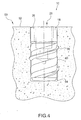
- the anchor may be flush with the masonry surface, as in the example illustrated in FIG. 4.
- the anchor may be sunken into the masonry hole or extend out from the hole.
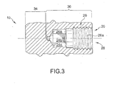
- anchor 10 is formed from a generally cylindrical stock metal and includes an external threaded portion 16 extending from a forward end 12 of anchor 10.
- An upper portion 18 extends from threaded portion 16 to fastening end 14.
- Anchor 10 includes a solid portion 34 and a hollow portion 36 whose longitudinal extent is defined by the length of a bore 20 extending from fastening end 14 towards forward end 12. Threaded portion 16 may extend over hollow portion 36, in addition to solid portion 34.
- bore 20 may be generally circular and includes a tool fitting 24 at one end and a fixture attachment 26, e.g., a helical thread 26a, at the opposite end adjacent opening 28 of bore 20.
- a camfer 30 may be formed at forward end 12 to assist with aligning anchor 10 with the masonry hole.
- Camfers 32a, 32b are also preferably formed at fastening end 14 and at the junction of threaded portion 16 and upper portion 18.
- tool fitting 24 is preferably formed into tool engagement surfaces that will reliably sustain high localized stresses resulting from torques applied by an anchor inserting tool, e.g. an oscillatory rotating hammer, hammer drill or impact wrench, as anchor 10 is driven into the masonry hole.
- tool fitting 24 corresponds to a female hex-type tool engagement, walls 24a, 24b, and 24c of which may be formed as shown in FIG. 3 .
- a hex-type fitting is preferred as it is a common type of tool engagement.
- tool fitting 24 may correspond to other types of engagements characterized by, e.g., longitudinally extending, opposed planar walls of appropriate depth for reacting torques required to tap masonry. It is preferred to have longitudinally extending so that the tool may be easily removed from bore 20 after anchor 10 is inserted into the masonry hole. In cases where, for example, tool fitting 24 is a helical thread, the tool may become locked in the bore. For this reason, it may be desirable to avoid using a helical thread for tool fitting 24. But it is not considered limiting on the invention that a particular type of tool engagement is used over another.
- Threaded portion 16 is of the type that is suitable for self-tapping masonry, as opposed to soft material (e.g., wood, plastic) or metal. Examples of thread patterns suited for tapping masonry are described in U.S. Pat. No. 6,419,435 to Gaudron and U.S. Pat. No. 5,957,6363 to Giannuzzi et al., the entire contents of which are incoporated by reference in their entirety for all purposes.
- threaded portion 16 includes a helical cutting thread 38, land 40, preferably formed as an arcute, e.g., hemispherical, land, and a valley disposed between land 40 and cutting thread 3 8 and defining a root diameter of the threading.
- Embodiments of the invention may have a hemishperical or planar land disposed between valleys which may be defined by a root diameter.
- the land may have a diameter that is equal to, or slightly less than the diameter of the hole so as to promote a frictional resistance between the anchor and the hole wall.
- Other types of masonry thread patterns may alternatively be used in place of the thread designs disclosed above. Accordingly, the invention is not limited to a particular type, or variety of self-tapping masonry thread.
- the cutting thread of the anchor may define a maximum diameter of the anchor, such as when the anchor is designed to be driven into a constant diameter hole and the exposed end, e.g., fastening end 14, is flush with, or disposed below the masonry surface when the anchor is fully inserted into the hole.
- the maximum diameter of upper portion 18 is preferably sized to be the same as, or slightly less than the diameter of the masonry hole so that fastening end 14 may be positioned within the masonry surface.
- Land 40 may be sized to have a maximum diameter extent that is equal to, or slightly greater than the maximum diameter of upper portion 18.
- Bore 20 preferably has a stepped diameter, with tool fitting 24 having a diameter that is slightly less than than the outer diameter of fixture attaching portion 26.
- a helical thread is preferably formed along the wall surface of fixture attaching portion 26 for engagement with a mating helical thread of the connecting structure. Other types of fastener engagements may be used in place of a helical thread.
- anchor 10 is shown embedded in masonry 50 and engaged with walls 54 defining a pre-formed hole.
- hole has a depth that allows fastening end 14 to be positioned approximately flush with surface 52.
- Cutting thread 38 is engaged with walls 54 and the diameter of upper portion 18 is approximately the same diameter as the hole.
- a preferred method for forming an anchor according to the invention uses cold forging.
- the steps include forming the bore of the anchor by drawing the piece using a punch press, followed by a second tool that taps the outer surface using a rolling pin.
- the Fixture attaching portion e.g., a helical thread, is then formed along an inner wall of the bore.
Landscapes
- Engineering & Computer Science (AREA)
- General Engineering & Computer Science (AREA)
- Mechanical Engineering (AREA)
- Dowels (AREA)
- Joining Of Building Structures In Genera (AREA)
Abstract
Description
Claims (22)
- An integrally formed, self tapping masonry anchor having a length extending between a first end and second end of the anchor, the anchor being insertable in a masonry hole using a tool, comprising:a helical thread of the type suited for tapping masonry, the thread extending from the first end to a first intermediate station disposed between the first and second ends;an axial bore adapted for releasably engaging an anchor inserting tool, the bore being formed at the second end, extending into the anchor and terminating at a second intermediate station that is one of approximately coincident with the first intermediate station and between the first intermediate station and the first end.
- The anchor of claim 1, further including a fastner engagement disposed between the tool engagement and the second end.
- The anchor of claim 2, wherein the fastner engagement is formed on a bore wall.
- The anchor of claim 1, wherein the second intermediate station is between the first intermediate station and the first end and at least a substantial portion of a tool engagement, formed in the bore, is located between the first intermediate station and the first end.
- The anchor of claim 1, further including a female hex for engaging the tool.
- A method for forming a self-tapping masonry anchor from a cylindrical blank, the blank having a first and second end defining a longitudinal extent of the blank, comprising the steps of:forming an axial bore extending from the first end and terminating at a first intermediate station disposed between the first and second ends; andforming a thread by rolling, the thread extending from the second end to a second intermediate station, the second intermediate station being one of approximately coincident with the first intermediate station and between the first intermediate station and the first end.
- The method of claim 6, wherein the forming an axial bore step includes the step of cold forging the axial bore.
- A method for inserting a self tapping masonry anchor in a masonry hole having a hole opening, the masonry anchor having formed thereon a helical threading of the type suited for tapping masonry, the anchor having first and second ends defining the longitudinal extent of the anchor, and an axial bore is formed in the anchor, comprising the steps of:engaging an anchor inserting tool with the bore;driving the anchor into the masonry hole until the second end is one of approximately flush with the hole opening and disposed below the hole opening; andremoving the tool from the bore including pulling the tool out of the bore.
- The method of claim 8, wherein the enagaging step includes engaging the tool with at least a portion of the bore that is devoid of a helical thread.
- The method of claim 8, wherein the engaging step includes engaging a hex-shaped portion of the bore with the tool.
- The method of claim 8, further including the step of attaching a structure to the anchor by engagement of a second engagement of the anchor with a corresponding mating portion of the structure.
- The method of claim 11, wherein the attaching a structure step includes attaching the structure to a second engagement formed in the bore.
- The method of claim 8, wherein the engaging step includes the step of pushing the tool into locking engaging with the bore.
- A masonry anchor that is embedded in a hole, comprising:a first anchor portion including a helical threading formed thereon, the thread being embedded in a helical groove of the hole formed by the thread as the anchor is driven into the hole by the tool; anda second anchor portion extending from the first portion to a location that is one of approximately flush with and recessed within the masonry hole, the second portion having formed therein an axial bore including a plurality of axially extending, opposed planar walls for releasably engaging a tool.
- The anchor of claim 14, wherein the hole is preformed as a hole having a constant hole diameter, the helical threading has a thread defining a major threading diameter, and the second anchor portion has a constant outer diameter that is less than the maj or threading diameter and approximately equal to the hole diameter.
- The anchor of claim 14, wherein the plurality of longitudinally extending, opposed planar walls is a female hex.
- An anchor for coupling a mounting structure to masonry by engagement of a fastener of the mounting structure to the anchor, the anchor having first and second ends defining a longitudinal extent of the anchor, comprising:a solid portion extending from the first end and terminating at an intermediate station located between the first and second ends;a hollow portion defined by an axial bore extending from the second end to the intermediate station, wherein a first bore portion defines a tool engagement for releasably engaging an anchor inserting tool, and a second bore portion for releasably securing a structure to the anchor; anda helical thread of the type suited for tapping masonry, the thread extending over a length that is no less than approximately the longitudinal extent of the solid portion.
- The anchor of claim 17, wherein no more than approximately 30% of the longitudinal extent of the anchor corresponds to the solid portion.
- The anchor of claim 18, wherein the threading extends over at least 60% of the longitudinal extent of the anchor.
- The anchor of claim 17, wherein the helical thread is a forged helical thread.
- An integrally formed, self-tapping masonry anchor having a length extending between a first end and second end of the anchor, the anchor being insertable in a masonry hole using a tool, comprising:thread means of the type suited for tapping masonry, and an axial bore adapted for releasably engaging an anchor moving tool, the thread means extending from the first end to a first intermediate station disposed between the first and second ends; andthe bore being formed at the second end, extending into the anchor and terminating at a second intermediate station that is between the first intermediate station and the first end.
- A method of forming a self-tapping masonry anchor from a cylindrical blank, the blank having first and second ends defining a longitudinal extent of the blank, comprising the steps of:forming a thread by rolling, the thread extending from the first end to a first intermediate station, the first intermediate station being located between the first and the second end is of the blank, andforming an axial bore extending from the second end and terminating at a second intermediate station disposed between the first end and the first intermediate station.
Applications Claiming Priority (2)
| Application Number | Priority Date | Filing Date | Title |
|---|---|---|---|
| US10/377,627 US7056075B2 (en) | 2003-03-04 | 2003-03-04 | Screw-type anchor |
| US377627 | 2003-03-04 |
Publications (3)
| Publication Number | Publication Date |
|---|---|
| EP1455098A2 true EP1455098A2 (en) | 2004-09-08 |
| EP1455098A3 EP1455098A3 (en) | 2004-12-15 |
| EP1455098B1 EP1455098B1 (en) | 2013-02-27 |
Family
ID=32824744
Family Applications (1)
| Application Number | Title | Priority Date | Filing Date |
|---|---|---|---|
| EP03252914A Expired - Lifetime EP1455098B1 (en) | 2003-03-04 | 2003-05-09 | Screw-type anchor |
Country Status (8)
| Country | Link |
|---|---|
| US (1) | US7056075B2 (en) |
| EP (1) | EP1455098B1 (en) |
| JP (2) | JP2004270913A (en) |
| CN (1) | CN100414122C (en) |
| AU (1) | AU2003204097B2 (en) |
| CA (1) | CA2427546A1 (en) |
| NO (1) | NO20040510L (en) |
| TW (1) | TWI227764B (en) |
Cited By (3)
| Publication number | Priority date | Publication date | Assignee | Title |
|---|---|---|---|---|
| DE102006002557A1 (en) * | 2006-01-10 | 2007-07-12 | Swg Schraubenwerk Gaisbach Gmbh | Concrete screw has head with same diameter as outer edge of thread and with drive recess for tool |
| EP1760329A3 (en) * | 2005-09-02 | 2012-02-01 | HILTI Aktiengesellschaft | Fastening part for hard substrates |
| WO2020083526A1 (en) * | 2018-10-21 | 2020-04-30 | Excalibur Screwbolts Limited | Improvements in or relating to anchor bolts |
Families Citing this family (11)
| Publication number | Priority date | Publication date | Assignee | Title |
|---|---|---|---|---|
| US20060149264A1 (en) * | 2004-12-20 | 2006-07-06 | Castaneda Javier E | Screw locking systems for bone plates |
| DE202005005872U1 (en) * | 2005-04-13 | 2005-06-16 | Textron Verbindungstechnik Gmbh & Co. Ohg | Steel sleeve for aluminium cylinder head bolt has an external self tapping thread to secure accurately into the head |
| DE202005021725U1 (en) * | 2005-09-02 | 2009-11-19 | Hilti Aktiengesellschaft | Fixing element for hard surfaces |
| DE102011002637A1 (en) * | 2011-01-13 | 2012-07-19 | Hilti Aktiengesellschaft | Screw anchor and method for producing a screw anchor |
| US9475109B2 (en) | 2013-12-31 | 2016-10-25 | Simpson Strong-Tie Company, Inc. | Method of manufacturing a hollow externally threaded fastener |
| USD739220S1 (en) | 2014-09-30 | 2015-09-22 | Lee Valley Tools Ltd. | Wall fastener |
| US9284972B1 (en) * | 2014-11-17 | 2016-03-15 | The Boeing Company | Panel-insert assembly and method |
| DE102017127175A1 (en) | 2017-11-17 | 2019-05-23 | Black & Decker Inc. | Screw anchor and manufacturing process |
| JP7115678B2 (en) * | 2018-06-26 | 2022-08-09 | 酒井工業株式会社 | Anchor fixing strength control method |
| US11239534B2 (en) * | 2018-12-11 | 2022-02-01 | GM Global Technology Operations LLC | Compression clamp battery connection system |
| US10933477B1 (en) * | 2020-02-12 | 2021-03-02 | Varun Jay Patel | Wall magnet anchor system |
Family Cites Families (40)
| Publication number | Priority date | Publication date | Assignee | Title |
|---|---|---|---|---|
| US636326A (en) * | 1899-02-27 | 1899-11-07 | Walter S Fisher | Shoe-polishing bracket. |
| US638326A (en) * | 1899-04-08 | 1899-12-05 | Edward L Farr | Printing-machine for oil-cloth, linoleum, & c. |
| US2560951A (en) * | 1948-10-18 | 1951-07-17 | Clover Ind Inc | Embedded screw-threaded socket |
| US2643573A (en) | 1950-12-13 | 1953-06-30 | Chester F Johnson | Masonry anchor bolt |
| US2942819A (en) | 1956-08-21 | 1960-06-28 | Robert E Brogan | Pipe-supporting device |
| US3117486A (en) * | 1960-06-17 | 1964-01-14 | Richard R Matthews | Self-tapping flush insert |
| US3190169A (en) * | 1961-12-04 | 1965-06-22 | Rosan Eng Corp | Insert having internal drive grooves |
| DE1575180B2 (en) * | 1967-03-08 | 1971-10-21 | Fa. H. Willy Krauss, 8432 Beilngries | THREADED SOCKET |
| US3844194A (en) * | 1973-02-14 | 1974-10-29 | Illinois Tool Works | Wedge anchor device |
| US4015504A (en) | 1973-11-15 | 1977-04-05 | Rosan Hydraulics Inc. | Self-boring fastener and methods of use thereof |
| US3937119A (en) * | 1974-12-23 | 1976-02-10 | Illinois Tool Works, Inc. | Masonry anchor device |
| DE2901066C2 (en) | 1979-01-12 | 1981-03-19 | TOX-Dübel-Werk Richard W. Heckhausen KG, 7762 Bodmann-Ludwigshafen | Expansion anchor |
| US4856951A (en) | 1984-05-11 | 1989-08-15 | Illinois Tool Works, Inc. | Fastening assembly for roofs of soft materials |
| US4637539A (en) | 1984-09-10 | 1987-01-20 | Turcott James L | Anchor bolt installation tool with depth stop |
| DE3519136A1 (en) * | 1985-05-29 | 1986-12-04 | Wolfgang G. 6200 Wiesbaden Prenosil | Screw with divided head shape |
| JPS62251513A (en) * | 1986-04-23 | 1987-11-02 | レツクスノ−ド・インコ−ポレ−テツド | Burying fitting |
| US4730970A (en) | 1986-11-12 | 1988-03-15 | Whyco Chromium Company | Selectively hardened self drilling fasteners |
| US4822223A (en) * | 1987-09-23 | 1989-04-18 | Williams William L | Wood insert |
| GB8819820D0 (en) | 1988-08-20 | 1988-09-21 | Tucker Fasteners Ltd | Anchors for fixing to dense concrete masonry &c |
| US5082405A (en) * | 1989-09-13 | 1992-01-21 | Witten Donald W | Potted insert for honeycomb panels |
| US5531553A (en) * | 1990-12-14 | 1996-07-02 | Bickford; Charles | Masonry fixing |
| US5263804A (en) | 1992-12-21 | 1993-11-23 | Illinois Tool Works Inc. | Adhesive anchor |
| DE4402478A1 (en) * | 1994-01-28 | 1995-08-03 | Fischer Artur Werke Gmbh | Expansion anchors made of metal and method for the production thereof |
| US5653563A (en) | 1995-10-26 | 1997-08-05 | Illinois Tool Works Inc. | Anchor |
| JP3291202B2 (en) * | 1996-06-19 | 2002-06-10 | 株式会社ヤマヒロ | Self drilling anchor |
| US5755542A (en) | 1996-08-06 | 1998-05-26 | Elco Textron, Inc. | Self-drilling/self-tapping fastener |
| JPH10246215A (en) * | 1997-03-07 | 1998-09-14 | Akira Miyake | Insert bolt |
| JPH10246216A (en) * | 1997-03-07 | 1998-09-14 | Akira Miyake | Insert bolt |
| US5957646A (en) | 1998-11-02 | 1999-09-28 | Anthony C. Giannuzzi | Enhanced strength screw-type masonry anchor |
| US6295773B1 (en) * | 1999-07-22 | 2001-10-02 | Louis Karl Alty | Devices and methods for securing an object to a first structure through a hole in a second structure |
| JP2001214915A (en) * | 2000-02-01 | 2001-08-10 | Nippon Light Metal Co Ltd | Self-tapping screw and method of joining aluminum members using the self-tapping screw |
| JP2001241423A (en) * | 2000-02-29 | 2001-09-07 | Kyoraku Co Ltd | Embedded nut |
| ES2231434T3 (en) * | 2000-05-19 | 2005-05-16 | Pama Reiter Stefan | THREADED HOSE SHAPED TAPE THREADING IN A SLOT. |
| JP2001349317A (en) * | 2000-06-08 | 2001-12-21 | Aoyama Seisakusho Co Ltd | Female screw member and method of manufacturing the same |
| US6419435B1 (en) | 2000-07-11 | 2002-07-16 | Paul Gaudron | Wedging masonry anchor bolt and sleeve anchor for masonry bolt used in cinder blocks |
| DE10034740B4 (en) * | 2000-07-17 | 2011-03-10 | Hilti Aktiengesellschaft | fastener |
| JP3589164B2 (en) * | 2000-08-11 | 2004-11-17 | 住友金属工業株式会社 | Extrusion processing method |
| US6676352B2 (en) * | 2001-03-13 | 2004-01-13 | Ju-Ching Chen-Chi | Fasteners with improved retaining effect |
| US6918727B2 (en) * | 2002-05-01 | 2005-07-19 | Joker Industrial Co., Ltd. | Anchoring screw with double heads and triple threads of different depths of thread |
| US6619899B1 (en) * | 2002-06-10 | 2003-09-16 | Power Products Iii, Llc | Cutting insert for fasteners |
-
2003
- 2003-03-04 US US10/377,627 patent/US7056075B2/en not_active Expired - Fee Related
- 2003-05-02 CA CA002427546A patent/CA2427546A1/en not_active Abandoned
- 2003-05-08 TW TW092112568A patent/TWI227764B/en not_active IP Right Cessation
- 2003-05-08 JP JP2003130787A patent/JP2004270913A/en active Pending
- 2003-05-08 AU AU2003204097A patent/AU2003204097B2/en not_active Ceased
- 2003-05-09 CN CNB031524583A patent/CN100414122C/en not_active Expired - Fee Related
- 2003-05-09 EP EP03252914A patent/EP1455098B1/en not_active Expired - Lifetime
-
2004
- 2004-01-29 NO NO20040510A patent/NO20040510L/en not_active Application Discontinuation
-
2009
- 2009-08-24 JP JP2009193697A patent/JP2010007858A/en active Pending
Cited By (3)
| Publication number | Priority date | Publication date | Assignee | Title |
|---|---|---|---|---|
| EP1760329A3 (en) * | 2005-09-02 | 2012-02-01 | HILTI Aktiengesellschaft | Fastening part for hard substrates |
| DE102006002557A1 (en) * | 2006-01-10 | 2007-07-12 | Swg Schraubenwerk Gaisbach Gmbh | Concrete screw has head with same diameter as outer edge of thread and with drive recess for tool |
| WO2020083526A1 (en) * | 2018-10-21 | 2020-04-30 | Excalibur Screwbolts Limited | Improvements in or relating to anchor bolts |
Also Published As
| Publication number | Publication date |
|---|---|
| TWI227764B (en) | 2005-02-11 |
| CA2427546A1 (en) | 2004-09-04 |
| CN1526963A (en) | 2004-09-08 |
| US20040175253A1 (en) | 2004-09-09 |
| EP1455098A3 (en) | 2004-12-15 |
| AU2003204097A1 (en) | 2004-09-30 |
| NO20040510L (en) | 2004-09-06 |
| US7056075B2 (en) | 2006-06-06 |
| JP2004270913A (en) | 2004-09-30 |
| TW200417696A (en) | 2004-09-16 |
| EP1455098B1 (en) | 2013-02-27 |
| JP2010007858A (en) | 2010-01-14 |
| CN100414122C (en) | 2008-08-27 |
| AU2003204097B2 (en) | 2008-05-22 |
Similar Documents
| Publication | Publication Date | Title |
|---|---|---|
| JP2010007858A (en) | Screw type anchor | |
| US6250866B1 (en) | Self-drilling, self-tapping screw for concrete blocks | |
| EP1000253B1 (en) | Improved fixing anchor | |
| JP3405932B2 (en) | Anchor bolt, its construction tool, and method of mounting anchor bolt using the construction tool | |
| EP1505304B1 (en) | Fastener for use with frangible material | |
| CA2483811C (en) | Self-drilling anchor | |
| US20100278614A1 (en) | Fixing device | |
| CA2494180A1 (en) | Tapping assist fastening element and method | |
| AU677568B2 (en) | Improved fixing | |
| CA2408774C (en) | Self-tapping bush-shaped screwed insert | |
| AU696219B2 (en) | All-metal expansible anchor and nail assembly | |
| EP1485627B1 (en) | Fixing device and method for fixing to a substrate | |
| EP0134231B2 (en) | Fixing element for knocking into a drilled hole | |
| HK1000383B (en) | Improved fixing | |
| HK1000383A1 (en) | Improved fixing | |
| WO2015044940A1 (en) | Apparatus and method for installing an anchor within a base material |
Legal Events
| Date | Code | Title | Description |
|---|---|---|---|
| PUAI | Public reference made under article 153(3) epc to a published international application that has entered the european phase |
Free format text: ORIGINAL CODE: 0009012 |
|
| AK | Designated contracting states |
Kind code of ref document: A2 Designated state(s): AT BE BG CH CY CZ DE DK EE ES FI FR GB GR HU IE IT LI LU MC NL PT RO SE SI SK TR |
|
| AX | Request for extension of the european patent |
Extension state: AL LT LV MK |
|
| PUAL | Search report despatched |
Free format text: ORIGINAL CODE: 0009013 |
|
| RIN1 | Information on inventor provided before grant (corrected) |
Inventor name: GAUDRON, PAUL Inventor name: POWERS, JEFFREY R. |
|
| AK | Designated contracting states |
Kind code of ref document: A3 Designated state(s): AT BE BG CH CY CZ DE DK EE ES FI FR GB GR HU IE IT LI LU MC NL PT RO SE SI SK TR |
|
| AX | Request for extension of the european patent |
Extension state: AL LT LV MK |
|
| RIC1 | Information provided on ipc code assigned before grant |
Ipc: 7F 16B 37/12 B Ipc: 7F 16B 13/00 A |
|
| 17P | Request for examination filed |
Effective date: 20050610 |
|
| AKX | Designation fees paid |
Designated state(s): AT BE BG CH CY CZ DE DK EE ES FI FR GB GR HU IE IT LI LU MC NL PT RO SE SI SK TR |
|
| GRAP | Despatch of communication of intention to grant a patent |
Free format text: ORIGINAL CODE: EPIDOSNIGR1 |
|
| GRAP | Despatch of communication of intention to grant a patent |
Free format text: ORIGINAL CODE: EPIDOSNIGR1 |
|
| RAP1 | Party data changed (applicant data changed or rights of an application transferred) |
Owner name: BLACK & DECKER INC. |
|
| GRAS | Grant fee paid |
Free format text: ORIGINAL CODE: EPIDOSNIGR3 |
|
| GRAA | (expected) grant |
Free format text: ORIGINAL CODE: 0009210 |
|
| AK | Designated contracting states |
Kind code of ref document: B1 Designated state(s): AT BE BG CH CY CZ DE DK EE ES FI FR GB GR HU IE IT LI LU MC NL PT RO SE SI SK TR |
|
| REG | Reference to a national code |
Ref country code: GB Ref legal event code: FG4D |
|
| REG | Reference to a national code |
Ref country code: CH Ref legal event code: EP |
|
| REG | Reference to a national code |
Ref country code: AT Ref legal event code: REF Ref document number: 598674 Country of ref document: AT Kind code of ref document: T Effective date: 20130315 |
|
| REG | Reference to a national code |
Ref country code: IE Ref legal event code: FG4D |
|
| REG | Reference to a national code |
Ref country code: DE Ref legal event code: R096 Ref document number: 60343351 Country of ref document: DE Effective date: 20130425 |
|
| REG | Reference to a national code |
Ref country code: NL Ref legal event code: T3 |
|
| REG | Reference to a national code |
Ref country code: AT Ref legal event code: MK05 Ref document number: 598674 Country of ref document: AT Kind code of ref document: T Effective date: 20130227 |
|
| PG25 | Lapsed in a contracting state [announced via postgrant information from national office to epo] |
Ref country code: ES Free format text: LAPSE BECAUSE OF FAILURE TO SUBMIT A TRANSLATION OF THE DESCRIPTION OR TO PAY THE FEE WITHIN THE PRESCRIBED TIME-LIMIT Effective date: 20130607 Ref country code: BG Free format text: LAPSE BECAUSE OF FAILURE TO SUBMIT A TRANSLATION OF THE DESCRIPTION OR TO PAY THE FEE WITHIN THE PRESCRIBED TIME-LIMIT Effective date: 20130527 Ref country code: SE Free format text: LAPSE BECAUSE OF FAILURE TO SUBMIT A TRANSLATION OF THE DESCRIPTION OR TO PAY THE FEE WITHIN THE PRESCRIBED TIME-LIMIT Effective date: 20130227 Ref country code: AT Free format text: LAPSE BECAUSE OF FAILURE TO SUBMIT A TRANSLATION OF THE DESCRIPTION OR TO PAY THE FEE WITHIN THE PRESCRIBED TIME-LIMIT Effective date: 20130227 |
|
| PG25 | Lapsed in a contracting state [announced via postgrant information from national office to epo] |
Ref country code: GR Free format text: LAPSE BECAUSE OF FAILURE TO SUBMIT A TRANSLATION OF THE DESCRIPTION OR TO PAY THE FEE WITHIN THE PRESCRIBED TIME-LIMIT Effective date: 20130528 Ref country code: BE Free format text: LAPSE BECAUSE OF FAILURE TO SUBMIT A TRANSLATION OF THE DESCRIPTION OR TO PAY THE FEE WITHIN THE PRESCRIBED TIME-LIMIT Effective date: 20130227 Ref country code: SI Free format text: LAPSE BECAUSE OF FAILURE TO SUBMIT A TRANSLATION OF THE DESCRIPTION OR TO PAY THE FEE WITHIN THE PRESCRIBED TIME-LIMIT Effective date: 20130227 Ref country code: PT Free format text: LAPSE BECAUSE OF FAILURE TO SUBMIT A TRANSLATION OF THE DESCRIPTION OR TO PAY THE FEE WITHIN THE PRESCRIBED TIME-LIMIT Effective date: 20130627 Ref country code: FI Free format text: LAPSE BECAUSE OF FAILURE TO SUBMIT A TRANSLATION OF THE DESCRIPTION OR TO PAY THE FEE WITHIN THE PRESCRIBED TIME-LIMIT Effective date: 20130227 |
|
| PG25 | Lapsed in a contracting state [announced via postgrant information from national office to epo] |
Ref country code: EE Free format text: LAPSE BECAUSE OF FAILURE TO SUBMIT A TRANSLATION OF THE DESCRIPTION OR TO PAY THE FEE WITHIN THE PRESCRIBED TIME-LIMIT Effective date: 20130227 Ref country code: DK Free format text: LAPSE BECAUSE OF FAILURE TO SUBMIT A TRANSLATION OF THE DESCRIPTION OR TO PAY THE FEE WITHIN THE PRESCRIBED TIME-LIMIT Effective date: 20130227 Ref country code: CZ Free format text: LAPSE BECAUSE OF FAILURE TO SUBMIT A TRANSLATION OF THE DESCRIPTION OR TO PAY THE FEE WITHIN THE PRESCRIBED TIME-LIMIT Effective date: 20130227 Ref country code: RO Free format text: LAPSE BECAUSE OF FAILURE TO SUBMIT A TRANSLATION OF THE DESCRIPTION OR TO PAY THE FEE WITHIN THE PRESCRIBED TIME-LIMIT Effective date: 20130227 Ref country code: SK Free format text: LAPSE BECAUSE OF FAILURE TO SUBMIT A TRANSLATION OF THE DESCRIPTION OR TO PAY THE FEE WITHIN THE PRESCRIBED TIME-LIMIT Effective date: 20130227 |
|
| PG25 | Lapsed in a contracting state [announced via postgrant information from national office to epo] |
Ref country code: CY Free format text: LAPSE BECAUSE OF FAILURE TO SUBMIT A TRANSLATION OF THE DESCRIPTION OR TO PAY THE FEE WITHIN THE PRESCRIBED TIME-LIMIT Effective date: 20130227 |
|
| PG25 | Lapsed in a contracting state [announced via postgrant information from national office to epo] |
Ref country code: IT Free format text: LAPSE BECAUSE OF FAILURE TO SUBMIT A TRANSLATION OF THE DESCRIPTION OR TO PAY THE FEE WITHIN THE PRESCRIBED TIME-LIMIT Effective date: 20130227 Ref country code: MC Free format text: LAPSE BECAUSE OF FAILURE TO SUBMIT A TRANSLATION OF THE DESCRIPTION OR TO PAY THE FEE WITHIN THE PRESCRIBED TIME-LIMIT Effective date: 20130227 |
|
| REG | Reference to a national code |
Ref country code: CH Ref legal event code: PL |
|
| PLBE | No opposition filed within time limit |
Free format text: ORIGINAL CODE: 0009261 |
|
| STAA | Information on the status of an ep patent application or granted ep patent |
Free format text: STATUS: NO OPPOSITION FILED WITHIN TIME LIMIT |
|
| PG25 | Lapsed in a contracting state [announced via postgrant information from national office to epo] |
Ref country code: LI Free format text: LAPSE BECAUSE OF NON-PAYMENT OF DUE FEES Effective date: 20130531 Ref country code: CH Free format text: LAPSE BECAUSE OF NON-PAYMENT OF DUE FEES Effective date: 20130531 |
|
| 26N | No opposition filed |
Effective date: 20131128 |
|
| REG | Reference to a national code |
Ref country code: IE Ref legal event code: MM4A |
|
| REG | Reference to a national code |
Ref country code: DE Ref legal event code: R097 Ref document number: 60343351 Country of ref document: DE Effective date: 20131128 |
|
| PG25 | Lapsed in a contracting state [announced via postgrant information from national office to epo] |
Ref country code: IE Free format text: LAPSE BECAUSE OF NON-PAYMENT OF DUE FEES Effective date: 20130509 |
|
| PG25 | Lapsed in a contracting state [announced via postgrant information from national office to epo] |
Ref country code: TR Free format text: LAPSE BECAUSE OF FAILURE TO SUBMIT A TRANSLATION OF THE DESCRIPTION OR TO PAY THE FEE WITHIN THE PRESCRIBED TIME-LIMIT Effective date: 20130227 |
|
| PG25 | Lapsed in a contracting state [announced via postgrant information from national office to epo] |
Ref country code: HU Free format text: LAPSE BECAUSE OF FAILURE TO SUBMIT A TRANSLATION OF THE DESCRIPTION OR TO PAY THE FEE WITHIN THE PRESCRIBED TIME-LIMIT; INVALID AB INITIO Effective date: 20030509 Ref country code: LU Free format text: LAPSE BECAUSE OF NON-PAYMENT OF DUE FEES Effective date: 20130509 |
|
| REG | Reference to a national code |
Ref country code: FR Ref legal event code: PLFP Year of fee payment: 14 |
|
| PGFP | Annual fee paid to national office [announced via postgrant information from national office to epo] |
Ref country code: NL Payment date: 20160510 Year of fee payment: 14 |
|
| PGFP | Annual fee paid to national office [announced via postgrant information from national office to epo] |
Ref country code: DE Payment date: 20160504 Year of fee payment: 14 Ref country code: GB Payment date: 20160504 Year of fee payment: 14 |
|
| PGFP | Annual fee paid to national office [announced via postgrant information from national office to epo] |
Ref country code: FR Payment date: 20160412 Year of fee payment: 14 |
|
| REG | Reference to a national code |
Ref country code: DE Ref legal event code: R119 Ref document number: 60343351 Country of ref document: DE |
|
| REG | Reference to a national code |
Ref country code: NL Ref legal event code: MM Effective date: 20170601 |
|
| GBPC | Gb: european patent ceased through non-payment of renewal fee |
Effective date: 20170509 |
|
| REG | Reference to a national code |
Ref country code: FR Ref legal event code: ST Effective date: 20180131 |
|
| PG25 | Lapsed in a contracting state [announced via postgrant information from national office to epo] |
Ref country code: NL Free format text: LAPSE BECAUSE OF NON-PAYMENT OF DUE FEES Effective date: 20170601 |
|
| PG25 | Lapsed in a contracting state [announced via postgrant information from national office to epo] |
Ref country code: GB Free format text: LAPSE BECAUSE OF NON-PAYMENT OF DUE FEES Effective date: 20170509 Ref country code: DE Free format text: LAPSE BECAUSE OF NON-PAYMENT OF DUE FEES Effective date: 20171201 |
|
| PG25 | Lapsed in a contracting state [announced via postgrant information from national office to epo] |
Ref country code: FR Free format text: LAPSE BECAUSE OF NON-PAYMENT OF DUE FEES Effective date: 20170531 |