EP1455062A1 - Heat exchange device - Google Patents
Heat exchange device Download PDFInfo
- Publication number
- EP1455062A1 EP1455062A1 EP02775479A EP02775479A EP1455062A1 EP 1455062 A1 EP1455062 A1 EP 1455062A1 EP 02775479 A EP02775479 A EP 02775479A EP 02775479 A EP02775479 A EP 02775479A EP 1455062 A1 EP1455062 A1 EP 1455062A1
- Authority
- EP
- European Patent Office
- Prior art keywords
- heat
- water
- exhaust gas
- passage
- exhaust
- Prior art date
- Legal status (The legal status is an assumption and is not a legal conclusion. Google has not performed a legal analysis and makes no representation as to the accuracy of the status listed.)
- Granted
Links
Images












Classifications
-
- F—MECHANICAL ENGINEERING; LIGHTING; HEATING; WEAPONS; BLASTING
- F01—MACHINES OR ENGINES IN GENERAL; ENGINE PLANTS IN GENERAL; STEAM ENGINES
- F01P—COOLING OF MACHINES OR ENGINES IN GENERAL; COOLING OF INTERNAL-COMBUSTION ENGINES
- F01P3/00—Liquid cooling
- F01P3/12—Arrangements for cooling other engine or machine parts
-
- F—MECHANICAL ENGINEERING; LIGHTING; HEATING; WEAPONS; BLASTING
- F01—MACHINES OR ENGINES IN GENERAL; ENGINE PLANTS IN GENERAL; STEAM ENGINES
- F01N—GAS-FLOW SILENCERS OR EXHAUST APPARATUS FOR MACHINES OR ENGINES IN GENERAL; GAS-FLOW SILENCERS OR EXHAUST APPARATUS FOR INTERNAL-COMBUSTION ENGINES
- F01N3/00—Exhaust or silencing apparatus having means for purifying, rendering innocuous, or otherwise treating exhaust
- F01N3/02—Exhaust or silencing apparatus having means for purifying, rendering innocuous, or otherwise treating exhaust for cooling, or for removing solid constituents of, exhaust
- F01N3/04—Exhaust or silencing apparatus having means for purifying, rendering innocuous, or otherwise treating exhaust for cooling, or for removing solid constituents of, exhaust using liquids
- F01N3/043—Exhaust or silencing apparatus having means for purifying, rendering innocuous, or otherwise treating exhaust for cooling, or for removing solid constituents of, exhaust using liquids without contact between liquid and exhaust gases
-
- F—MECHANICAL ENGINEERING; LIGHTING; HEATING; WEAPONS; BLASTING
- F01—MACHINES OR ENGINES IN GENERAL; ENGINE PLANTS IN GENERAL; STEAM ENGINES
- F01N—GAS-FLOW SILENCERS OR EXHAUST APPARATUS FOR MACHINES OR ENGINES IN GENERAL; GAS-FLOW SILENCERS OR EXHAUST APPARATUS FOR INTERNAL-COMBUSTION ENGINES
- F01N3/00—Exhaust or silencing apparatus having means for purifying, rendering innocuous, or otherwise treating exhaust
- F01N3/02—Exhaust or silencing apparatus having means for purifying, rendering innocuous, or otherwise treating exhaust for cooling, or for removing solid constituents of, exhaust
- F01N3/04—Exhaust or silencing apparatus having means for purifying, rendering innocuous, or otherwise treating exhaust for cooling, or for removing solid constituents of, exhaust using liquids
- F01N3/043—Exhaust or silencing apparatus having means for purifying, rendering innocuous, or otherwise treating exhaust for cooling, or for removing solid constituents of, exhaust using liquids without contact between liquid and exhaust gases
- F01N3/046—Exhaust manifolds with cooling jacket
-
- F—MECHANICAL ENGINEERING; LIGHTING; HEATING; WEAPONS; BLASTING
- F01—MACHINES OR ENGINES IN GENERAL; ENGINE PLANTS IN GENERAL; STEAM ENGINES
- F01N—GAS-FLOW SILENCERS OR EXHAUST APPARATUS FOR MACHINES OR ENGINES IN GENERAL; GAS-FLOW SILENCERS OR EXHAUST APPARATUS FOR INTERNAL-COMBUSTION ENGINES
- F01N5/00—Exhaust or silencing apparatus combined or associated with devices profiting by exhaust energy
- F01N5/02—Exhaust or silencing apparatus combined or associated with devices profiting by exhaust energy the devices using heat
-
- F—MECHANICAL ENGINEERING; LIGHTING; HEATING; WEAPONS; BLASTING
- F01—MACHINES OR ENGINES IN GENERAL; ENGINE PLANTS IN GENERAL; STEAM ENGINES
- F01P—COOLING OF MACHINES OR ENGINES IN GENERAL; COOLING OF INTERNAL-COMBUSTION ENGINES
- F01P3/00—Liquid cooling
- F01P3/22—Liquid cooling characterised by evaporation and condensation of coolant in closed cycles; characterised by the coolant reaching higher temperatures than normal atmospheric boiling-point
-
- F—MECHANICAL ENGINEERING; LIGHTING; HEATING; WEAPONS; BLASTING
- F02—COMBUSTION ENGINES; HOT-GAS OR COMBUSTION-PRODUCT ENGINE PLANTS
- F02G—HOT GAS OR COMBUSTION-PRODUCT POSITIVE-DISPLACEMENT ENGINE PLANTS; USE OF WASTE HEAT OF COMBUSTION ENGINES; NOT OTHERWISE PROVIDED FOR
- F02G5/00—Profiting from waste heat of combustion engines, not otherwise provided for
- F02G5/02—Profiting from waste heat of exhaust gases
-
- F—MECHANICAL ENGINEERING; LIGHTING; HEATING; WEAPONS; BLASTING
- F22—STEAM GENERATION
- F22B—METHODS OF STEAM GENERATION; STEAM BOILERS
- F22B1/00—Methods of steam generation characterised by form of heating method
- F22B1/02—Methods of steam generation characterised by form of heating method by exploitation of the heat content of hot heat carriers
- F22B1/18—Methods of steam generation characterised by form of heating method by exploitation of the heat content of hot heat carriers the heat carrier being a hot gas, e.g. waste gas such as exhaust gas of internal-combustion engines
- F22B1/1807—Methods of steam generation characterised by form of heating method by exploitation of the heat content of hot heat carriers the heat carrier being a hot gas, e.g. waste gas such as exhaust gas of internal-combustion engines using the exhaust gases of combustion engines
-
- F—MECHANICAL ENGINEERING; LIGHTING; HEATING; WEAPONS; BLASTING
- F28—HEAT EXCHANGE IN GENERAL
- F28D—HEAT-EXCHANGE APPARATUS, NOT PROVIDED FOR IN ANOTHER SUBCLASS, IN WHICH THE HEAT-EXCHANGE MEDIA DO NOT COME INTO DIRECT CONTACT
- F28D21/00—Heat-exchange apparatus not covered by any of the groups F28D1/00 - F28D20/00
- F28D21/0001—Recuperative heat exchangers
- F28D21/0003—Recuperative heat exchangers the heat being recuperated from exhaust gases
- F28D21/001—Recuperative heat exchangers the heat being recuperated from exhaust gases for thermal power plants or industrial processes
-
- F—MECHANICAL ENGINEERING; LIGHTING; HEATING; WEAPONS; BLASTING
- F28—HEAT EXCHANGE IN GENERAL
- F28D—HEAT-EXCHANGE APPARATUS, NOT PROVIDED FOR IN ANOTHER SUBCLASS, IN WHICH THE HEAT-EXCHANGE MEDIA DO NOT COME INTO DIRECT CONTACT
- F28D7/00—Heat-exchange apparatus having stationary tubular conduit assemblies for both heat-exchange media, the media being in contact with different sides of a conduit wall
- F28D7/16—Heat-exchange apparatus having stationary tubular conduit assemblies for both heat-exchange media, the media being in contact with different sides of a conduit wall the conduits being arranged in parallel spaced relation
- F28D7/163—Heat-exchange apparatus having stationary tubular conduit assemblies for both heat-exchange media, the media being in contact with different sides of a conduit wall the conduits being arranged in parallel spaced relation with conduit assemblies having a particular shape, e.g. square or annular; with assemblies of conduits having different geometrical features; with multiple groups of conduits connected in series or parallel and arranged inside common casing
- F28D7/1638—Heat-exchange apparatus having stationary tubular conduit assemblies for both heat-exchange media, the media being in contact with different sides of a conduit wall the conduits being arranged in parallel spaced relation with conduit assemblies having a particular shape, e.g. square or annular; with assemblies of conduits having different geometrical features; with multiple groups of conduits connected in series or parallel and arranged inside common casing with particular pattern of flow or the heat exchange medium flowing inside the conduits assemblies, e.g. change of flow direction from one conduit assembly to another one
-
- F—MECHANICAL ENGINEERING; LIGHTING; HEATING; WEAPONS; BLASTING
- F28—HEAT EXCHANGE IN GENERAL
- F28F—DETAILS OF HEAT-EXCHANGE AND HEAT-TRANSFER APPARATUS, OF GENERAL APPLICATION
- F28F1/00—Tubular elements; Assemblies of tubular elements
- F28F1/10—Tubular elements and assemblies thereof with means for increasing heat-transfer area, e.g. with fins, with projections, with recesses
- F28F1/12—Tubular elements and assemblies thereof with means for increasing heat-transfer area, e.g. with fins, with projections, with recesses the means being only outside the tubular element
- F28F1/24—Tubular elements and assemblies thereof with means for increasing heat-transfer area, e.g. with fins, with projections, with recesses the means being only outside the tubular element and extending transversely
- F28F1/32—Tubular elements and assemblies thereof with means for increasing heat-transfer area, e.g. with fins, with projections, with recesses the means being only outside the tubular element and extending transversely the means having portions engaging further tubular elements
-
- F—MECHANICAL ENGINEERING; LIGHTING; HEATING; WEAPONS; BLASTING
- F01—MACHINES OR ENGINES IN GENERAL; ENGINE PLANTS IN GENERAL; STEAM ENGINES
- F01N—GAS-FLOW SILENCERS OR EXHAUST APPARATUS FOR MACHINES OR ENGINES IN GENERAL; GAS-FLOW SILENCERS OR EXHAUST APPARATUS FOR INTERNAL-COMBUSTION ENGINES
- F01N2240/00—Combination or association of two or more different exhaust treating devices, or of at least one such device with an auxiliary device, not covered by indexing codes F01N2230/00 or F01N2250/00, one of the devices being
- F01N2240/02—Combination or association of two or more different exhaust treating devices, or of at least one such device with an auxiliary device, not covered by indexing codes F01N2230/00 or F01N2250/00, one of the devices being a heat exchanger
-
- F—MECHANICAL ENGINEERING; LIGHTING; HEATING; WEAPONS; BLASTING
- F01—MACHINES OR ENGINES IN GENERAL; ENGINE PLANTS IN GENERAL; STEAM ENGINES
- F01P—COOLING OF MACHINES OR ENGINES IN GENERAL; COOLING OF INTERNAL-COMBUSTION ENGINES
- F01P2060/00—Cooling circuits using auxiliaries
- F01P2060/16—Outlet manifold
-
- Y—GENERAL TAGGING OF NEW TECHNOLOGICAL DEVELOPMENTS; GENERAL TAGGING OF CROSS-SECTIONAL TECHNOLOGIES SPANNING OVER SEVERAL SECTIONS OF THE IPC; TECHNICAL SUBJECTS COVERED BY FORMER USPC CROSS-REFERENCE ART COLLECTIONS [XRACs] AND DIGESTS
- Y02—TECHNOLOGIES OR APPLICATIONS FOR MITIGATION OR ADAPTATION AGAINST CLIMATE CHANGE
- Y02E—REDUCTION OF GREENHOUSE GAS [GHG] EMISSIONS, RELATED TO ENERGY GENERATION, TRANSMISSION OR DISTRIBUTION
- Y02E20/00—Combustion technologies with mitigation potential
- Y02E20/30—Technologies for a more efficient combustion or heat usage
-
- Y—GENERAL TAGGING OF NEW TECHNOLOGICAL DEVELOPMENTS; GENERAL TAGGING OF CROSS-SECTIONAL TECHNOLOGIES SPANNING OVER SEVERAL SECTIONS OF THE IPC; TECHNICAL SUBJECTS COVERED BY FORMER USPC CROSS-REFERENCE ART COLLECTIONS [XRACs] AND DIGESTS
- Y02—TECHNOLOGIES OR APPLICATIONS FOR MITIGATION OR ADAPTATION AGAINST CLIMATE CHANGE
- Y02T—CLIMATE CHANGE MITIGATION TECHNOLOGIES RELATED TO TRANSPORTATION
- Y02T10/00—Road transport of goods or passengers
- Y02T10/10—Internal combustion engine [ICE] based vehicles
- Y02T10/12—Improving ICE efficiencies
Definitions
- the present invention relates to a heat exchange system for recovering with a heat medium the thermal energy of a high temperature fluid flowing through the interior of a fluid passage extending from a heat source.
- This evaporator improves the heat exchange efficiency by making the water flow in a direction opposite to the direction of flow of the exhaust gas, which is discharged from a combustion chamber of the internal combustion engine, that is, from the downstream side to the upstream side of the flow of exhaust gas, thus ensuring that there is a temperature difference between the exhaust gas and the water along the whole of a water passage.
- a heat exchange system for recovering with a heat medium the thermal energy of a high temperature fluid flowing through the interior of a fluid passage extending from a heat source, characterized in that the heat exchange system includes a first heat exchanger positioned on the upstream side of the fluid passage, and a second heat exchanger positioned on the downstream side of the fluid passage, the heat medium flows through the interior of a first heat medium passage, which is provided in the first heat exchanger, so as to be parallel to the flow of the high temperature fluid, the heat medium flows through the interior of a second heat medium passage, which is provided in the second heat exchanger, so as to oppose the flow of the high temperature fluid, and the downstream side of the first heat medium passage merges with the second heat medium passage.
- an upstream section of the fluid passage which has a high temperature since it is close to the heat source, can be cooled effectively with the heat medium at a low temperature, the escape of heat from the upstream section can be suppressed, thus enhancing the efficiency of recovery of thermal energy, a location that requires cooling can be cooled effectively, thus suppressing thermal expansion, and dimensional and positional precision, etc. can be maintained, thus ensuring the function of the location that requires cooling.
- the second heat exchanger positioned on the downstream side of the fluid passage, since the heat medium flows through the interior of the second heat medium passage so as to oppose the flow of the high temperature fluid, it is possible to ensure that there is a temperature difference between the heat medium and the high temperature fluid along the whole length of the second heat medium passage, thus improving the heat exchanger efficiency. In this way, by cooperation between the first and second heat exchangers it is possible to reduce the loss of thermal energy by suppressing dissipation of heat from the heat source while improving the heat exchange efficiency between the high temperature fluid and the heat medium.
- the combustion chamber of the internal combustion engine is the heat source
- the exhaust gas discharged from the combustion chamber is the high temperature fluid
- the first heat exchanger is provided in the vicinity of the exhaust port of the internal combustion engine, it is possible to recover effectively with the first heat exchanger the thermal energy of the exhaust gas discharged into the exhaust port from the combustion chamber of the internal combustion engine, suppress thermal expansion by cooling effectively a location that requires cooling, and ensure the function of the location that requires cooling by maintaining the dimensional and positional precision, etc.
- the upstream section of the first heat medium passage cools the section of the exhaust port that requires cooling, it is possible to cool effectively the section of the exhaust port that requires cooling by low temperature heat medium that has not yet fully carried out heat exchange, suppress thermal expansion by cooling effectively the location that requires cooling, and ensure the function of the location that requires cooling by maintaining the dimensional and positional precision, etc.
- FIG. 1 to FIG. 23 show one embodiment of the present invention
- FIG. 1 is a diagram showing the overall arrangement of a Rankine cycle system
- FIG. 2 is a vertical sectional view of the surroundings of a cylinder head of an internal combustion engine
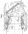
- FIG. 3 is an enlarged view of a part 3 in FIG. 2
- FIG. 4 is a view from arrowed line 4-4 in FIG. 2
- FIG. 5 is a sectional view along line 5-5 in FIG. 4
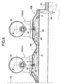
- FIG. 6 is a sectional view along line 6-6 in FIG. 4
- FIG. 7 is a partially cutaway perspective view of an independent exhaust port
- FIG. 8 is a view from arrow 8 in FIG. 7
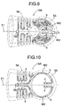
- FIG. 9 is a view from arrow 9 in FIG. 8
- FIG. 1 is a diagram showing the overall arrangement of a Rankine cycle system
- FIG. 2 is a vertical sectional view of the surroundings of a cylinder head of an internal combustion engine
- FIG. 3 is an enlarged view of a part 3 in
- FIG. 10 is a view from arrow 10 in FIG. 8;
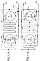
- FIG. 11A and FIG. 11B are schematic views showing the flow of water in a grouped exhaust port;
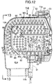
- FIG. 12 is an enlarged sectional view of an essential part in FIG. 2;
- FIG. 13 is a view from arrowed line 13-13 in FIG. 12;
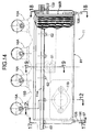
- FIG. 14 is a view from arrow 14 in FIG. 12;
- FIG. 15 is a sectional view along line 15-15 in FIG. 12;
- FIG. 16 is an enlarged view of a part 16 in FIG. 15;
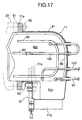
- FIG. 17 is a sectional view along line 17-17 in FIG. 14;
- FIG. 18 is a sectional view along line 18-18 in FIG. 14;
- FIG. 19 is a sectional view along line 19-19 in FIG. 14;
- FIG. 12 is an enlarged sectional view of an essential part in FIG. 2
- FIG. 13 is a view from arrowed line 13-13 in FIG. 12
- FIG. 14 is a view
- FIG. 1 shows the overall arrangement of a Rankine cycle system to which the present invention is applied.
- the Rankine cycle system which recovers the thermal energy of an exhaust gas of an internal combustion engine E and converts it into mechanical energy, includes a main evaporator 11 that heats water with exhaust gas discharged from the internal combustion engine E so as to generate high temperature, high pressure steam, an expander 12 that is operated by the high temperature, high pressure steam generated by the main evaporator 11 so as to generate mechanical energy, a condenser 13 that cools decreased temperature, decreased pressure steam that has completed work in the expander 12 so as to turn it back into water, a reservoir tank 14 for collecting water discharged from the condenser 13, and a supply pump 15 for pressurizing the water collected in the reservoir tank 14.
- a portion of the water discharged from the supply pump 15 is supplied to the main evaporator 11, which is provided downstream of an exhaust port 16 of the internal combustion engine E, turns into high temperature, high pressure steam in the main evaporator 11, and is supplied to the expander 12, and the rest of water discharged from the supply pump 15 is heated while passing through an auxiliary evaporator 17 provided on the outer periphery of the exhaust port 16, and then merges into the main evaporator 11 at a predetermined position.
- the main evaporator 11 carries out heat exchange mainly with the exhaust gas discharged from the exhaust port 16 and generates steam, but the auxiliary evaporator 17 carries out heat exchange not only with the exhaust gas flowing through the exhaust port 16 but also with the exhaust port 16 itself, which is in contact with a high temperature exhaust gas, thus generating steam and simultaneously cooling the exhaust port 16.
- a cylinder head 20 and a head cover 21 are joined to a cylinder block 19 of the in-line four-cylinder internal combustion engine E, and four combustion chambers 24 are formed between the lower face of the cylinder head 20 and the upper face of each of four pistons 23 slidably fitted in four cylinder sleeves 22 housed in the cylinder block 19.
- Formed in the cylinder head 20 are intake ports 26 and exhaust ports 16, which communicate with the corresponding combustion chambers 24.
- An intake valve seat 27 at the downstream end of the intake port 26 is opened and closed by a head 28a of an intake valve 28, and an exhaust valve seat 29 at the upstream end of the exhaust port 16 is opened and closed by a head 30a of an exhaust valve 30.
- the exhaust port 16 is formed from four independent exhaust ports 16A and one grouped exhaust port 16B, each thereof being made of a member that is separate from the cylinder head 20 and fitted in the cylinder head 20.
- an exhaust rocker arm 38 rockably supported by the exhaust rocker arm shaft 33 abuts against an exhaust cam 39 provided on the camshaft 31, and the other end thereof abuts against the upper end of a stem 30b of the exhaust valve 30, which is slidably supported by an exhaust valve guide 40 provided in the cylinder head 20 and is urged upward by a valve spring 41.
- the exhaust port 16 is formed from the four independent exhaust ports 16A, which are positioned on the upstream side of the flow of exhaust gas, and the single grouped exhaust port 16B, which communicates with the downstream side of the independent exhaust ports 16A, and an end portion on the upstream side of the main evaporator 11 is fitted into the inside of the grouped exhaust port 16B.
- the auxiliary evaporator 17 is provided so as to straddle the independent exhaust ports 16A and the grouped exhaust port 16B communicating with the downstream side thereof.
- an opening 51 a through which the stem 30b of the exhaust valve 30 runs is formed in an upper wall of the first port member 51, and the lower end of the exhaust valve guide 40 is fitted via a seal 57 in an opening 52a formed on an upper wall of the first cover member 52.
- the water passage W2 extends linearly from the water inlet 59 along a lower face of the downstream portion 58 (part a ), moves therefrom to the upstream portion 55, extends in a semicircular shape around the head 30a of the exhaust valve 30 (part b ), extends therefrom linearly upward along the stem 30b of the exhaust valve 30 up to the vicinity of the lower end of the exhaust valve guide 40 (part c ), extends therefrom toward the head 30a of the exhaust valve 30 while bent in a zigzag shape (part d ), returns therefrom back to the downstream portion 58, and extends toward the water outlet 60 while bent in a zigzag shape (part e ).
- the grouped exhaust port 16B includes a rectangular frame-shaped flange 61, and by tightening a plurality of bolts 62 running through a flange 11 a of the main evaporator 11 to the cylinder head 20 the main evaporator 11 and the grouped exhaust port 16B are together secured to the cylinder head 20 (see FIG. 2).
- the downstream end of a pressed sheet material third port member 63 is welded to the flange 61 of the grouped exhaust port 16B, and four openings 63a formed in the upstream end of the third port member 63 communicate with exits of the four independent exhaust ports 16A.
- the water passage W1 starting at a water inlet 65 provided on an end portion of the flange 61 extends linearly along an inner face of the fourth port member 64 (part f ), and extends linearly therefrom along an inner face of the third port member 63 (part g ).
- a coupling 66 is provided in the part g , and the water inlet 59 of the independent exhaust port 16A(1) is connected to this coupling 66.
- the water passage W1 extending from a coupling 67 to which the water outlet 60 of the independent exhaust port 16A(1) is connected extends linearly along the inner face of the third port member 63 (part h ), extends therefrom along the inner face of the third port member 63 in a zigzag shape (part i ), extends linearly therefrom along the inner face of the third port member 63 (part j ), turns downward through 90°, and communicates with the water outlet 68.
- the water outlet 68 communicates with an intermediate portion of the main evaporator 11 via a connecting pipe 106, which will be described later.
- the partition wall 86 is arranged in the shape shown in FIG. 12, and forms a bent exhaust gas passage between adjacent heat transfer plates 83.
- the exhaust gas passage is formed from a first exhaust gas passage 87, a second exhaust gas passage 88, and a third exhaust gas passage 89, the first exhaust gas passage 87 communicating with the downstream end of the auxiliary evaporator 17 and extending linearly in a direction away from the cylinder head 20, the second exhaust gas passage 88 bending through 180° at the downstream end of the first exhaust gas passage 87 and extending linearly toward the cylinder head 20, and the third exhaust gas passage 89 bending through 180° at the downstream end of the second exhaust gas passage 88, extending in a direction away from the cylinder head 20, further bending through 90°, and extending downward so as to form an overall L-shape.
- an oxygen concentration sensor 91 is mounted on the middle of the lower face of the main evaporator 11, and a detection portion 91 a at the extremity thereof faces the first exhaust gas passage 87.
- an oxygen concentration sensor cooling portion 92 is provided on the lower face of the main evaporator 11 on which the oxygen concentration sensor 91 is mounted.
- a flat upper face of the oxygen concentration sensor cooling portion 92 faces the first exhaust gas passage 87 via the partition wall 86, and a lower face thereof faces the atmosphere via the casing 81.
- the oxygen concentration sensor cooling portion 92 includes a plurality of pipe members 93, which run through the heat transfer plates 83 and are joined thereto by brazing.
- a water inlet pipe 100 communicating with the downstream side of the supply pump 15 runs through a rear face of the casing 81 of the main evaporator 11 and reaches an outer face of the outer plate 95 of the left-hand (when facing the cylinder head 20) header 96L, and is connected to two of the pipe members 93 via a bifurcated coupling 101.
- These two pipe members 93 form the beginning of two lines of water passages W4, and adjacent pipe members 93 of each line are connected via U-shaped couplings 102 in the left and right headers 96L and 96R and via five couplings 103 in a space surrounding the oxygen concentration sensor 91, thus forming the water passages W4 in a zigzag shape.
- the downstream ends of the two line water passages W4 communicate via couplings 104 and connecting pipes 105 with the water inlets 65 (see FIG. 5) of the auxiliary evaporator 17 formed within the flanges 11 a and 61.
- the two connecting pipes 106 communicating with the water outlets of the water passages W2 of the auxiliary evaporator 17 extend to the exterior of the casing 81 through the outside of the headers 96L and 96R, bend through 180°, re-enter the interior of the casing 81, and are connected to the pipe members 90 of the cooling water passages W3 via bifurcated couplings 107 provided in the headers 96L and 96R.
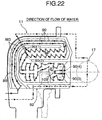
- the position of the pipe members 90 connected to the connecting pipes 106 is in the vicinity of the upstream end of the second exhaust gas passage 88 as shown by the reference numerals 90(1) and 90(2) in FIG. 22.
- the heat of the exhaust gas is transferred from the large number of heat transfer plates 83, which have a large surface area and are arranged at a small pitch, to the water flowing through the large number of pipe members 90, it is possible to ensure that there is a sufficient area of heat exchange between the exhaust gas and the water. Accordingly, even when the flow rate of the exhaust gas is reduced, that is, when the cross-sectional area of the exhaust gas flow path in the main evaporator 11 is increased, sufficient heat exchange efficiency can be obtained, and suppressing an increase in the back pressure of the exhaust passage can prevent any decrease in the output of the internal combustion engine E.
- the partition wall 86 can be provided in any shape by forming only the abutment sections 84 and 85, and the first to third exhaust gas passages 87, 88, and 89, which are bent, can be formed without employing any special component for providing the partition wall 86.
- the density of the pipe members 90 is low in the first exhaust gas passage 87, which is on the upstream side of the flow of the exhaust gas, and the density of the pipe members 90 gradually increases therefrom toward the third exhaust gas passage 89, which is on the downstream side, by reducing the density of the pipe members 90 in the upstream section where the exhaust gas has a high temperature and a large volume and the flow rate is high it is possible to minimize the pressure loss due to impingement of the exhaust gas on the pipe members 90, and by increasing the density of the pipe members 90 in the downstream section where the exhaust gas has a low temperature and a small volume and the flow rate is low it is possible to ensure that there is sufficient contact between the exhaust gas and the pipe members 90 and improve the heat exchange efficiency.
- the rest of the low temperature water discharged from the supply pump 15 enters the interior of the left-hand header 96L of the casing 81 of the main evaporator 11 via the water inlet pipe 100 (see FIG. 15), and the flow thereof is divided into the two lines of water passages W4 via the coupling 101.
- Water that has flowed in a zigzag shape through the interior of the pipe members 93 forming each of the water passages W4 is first merged in the H-shaped coupling 103 in the vicinity of the oxygen concentration sensor 91, is then divided again, further flows in a zigzag shape through the interior of the pipe members 93, then flows from the left and right headers 96L and 96R through the couplings 104, the connecting pipes 105, and the water inlets 65, and is then supplied to the auxiliary evaporator 17.
- the third exhaust gas passage 89 which is positioned on the downstream side of the flow of exhaust gas and to which water having the lowest temperature is supplied, is disposed in a radially outer portion of the main evaporator 11, and the oxygen concentration sensor cooling portion 92, to which water having the lowest temperature is supplied, is disposed in a radially outer portion of the main evaporator 11, that is, since the outsides of the first exhaust gas passage 87 and the second exhaust gas passage 88, which reach a high temperature due to the passage of high temperature exhaust gas, are surrounded by the third exhaust gas passage 89 and the oxygen concentration sensor cooling portion 92, which reach a low temperature due to the passage of low temperature water, it is possible to minimize the dissipation of thermal energy to the outside of the main evaporator 11,
- FIG. 11A and FIG. 11B water discharged from the oxygen concentration sensor cooling portion 92 flows into the water passage W1 from the water inlet 65 of the grouped exhaust port 16B and the flow is divided into the first line and the second line.
- the first line shown in FIG. 11A has a route that reaches the water outlet 68 via the part f and the part g of the water passage W1, the coupling 66, the water passage W2 of the independent exhaust port 16A(1), the coupling 67, and the part h , the part i , and the part j of the water passage W1.
- 11B has a route that reaches the water outlet 68 via the part f , the part g , the part k , the part m , the part n , and the part o of the water passage W1, the coupling 69, the water passage W2 of the independent exhaust port 16A(2), and the part j of the water passage W1. Since in the first line the first half of the water passage W1 is short and the second half thereof is long, and in the second line the first half of the water passage W1 is long and the second half thereof is short, the overall length of the water passage W1 in the two lines is equalized, thus making the amount supplied substantially equal, preventing an imbalance in the waste heat recovery, and improving the heat exchange efficiency.
- the structures of the water passages W2 provided in the two independent exhaust ports 16A(1) and 16A(2) are identical, and water supplied from the water inlet 59 branches so as to sandwich the plane of symmetry P1, passes through the part a , the part b , the part c , the part d , and the part e , is merged, and is then discharged via the water outlet 60.
- the auxiliary evaporator 17 is arranged so that the surroundings of the exhaust port 16, which reach a high temperature due to the passage of exhaust gas, are surrounded by the water passages W1 and W2, the exhaust gas heat dissipated from the exhaust port 16 via the cylinder head 20 can be recovered effectively as high temperature, high pressure steam.
- the water supplied to the water passages W1 and W2 is comparatively low temperature water that has only passed through the oxygen concentration sensor cooling portion 92 after being discharged from the supply pump 15, the surroundings of the exhaust port 16 can be cooled effectively, and high temperature, high pressure steam can be generated, thus enhancing the waste heat recovery effect of the internal combustion engine E.
- the heat of exhaust gas easily escapes to the outside via the exhaust valve 30, intensive cooling, with low temperature water, of the section that requires cooling of the internal combustion engine E, that is, the exhaust valve seat 29, with which the head 30a of the exhaust valve 30 makes contact, and the vicinity of the exhaust valve guide 40, with which the stem 30b of the exhaust valve 30 makes contact, enables the escape of heat via the exhaust valve 30 to be suppressed, thus further enhancing the waste heat recovery effect, and enables thermal expansion of the exhaust valve 30, the exhaust valve seat 29, and the exhaust valve guide 40, etc. to be suppressed, thus maintaining dimensional and positional precision and thereby maintaining desired functions thereof.
- Water that has passed through the auxiliary evaporator 17 passes from the connecting pipes 106 (see FIG. 17 and FIG. 18) through the couplings 107 (see FIG. 20) provided in the left and right headers 96L and 96R, and is merged in the pipe members 90 of the second exhaust gas passage 88 of the main evaporator 11.
- the waste heat recovery effect can be further improved.
- This control of water temperature can be carried out by regulating the flow rate ratio when splitting the flow of water discharged from the supply pump 15 into the main evaporator 11 side and the auxiliary evaporator 17 side.
- the heat exchanger is exemplified by the evaporators 11 and 17, but the heat exchanger of the present invention is not limited to an evaporator.
- water is illustrated as the heat medium, but the heat medium of the present invention is not limited to water.
- the present invention can be suitably applied to an evaporator for a Rankine cycle system and, in particular, to an evaporator for a Rankine cycle system that recovers the thermal energy of the exhaust gas of an internal combustion engine of an automobile and converts it into mechanical energy
- the present invention can also be applied to a heat exchanger for any purpose.
Landscapes
- Engineering & Computer Science (AREA)
- Mechanical Engineering (AREA)
- General Engineering & Computer Science (AREA)
- Chemical & Material Sciences (AREA)
- Combustion & Propulsion (AREA)
- Physics & Mathematics (AREA)
- Thermal Sciences (AREA)
- Geometry (AREA)
- Life Sciences & Earth Sciences (AREA)
- Sustainable Development (AREA)
- Sustainable Energy (AREA)
- Heat-Exchange Devices With Radiators And Conduit Assemblies (AREA)
- Exhaust-Gas Circulating Devices (AREA)
- Engine Equipment That Uses Special Cycles (AREA)
Abstract
Description
Claims (6)
- A heat exchange system for recovering with a heat medium the thermal energy of a high temperature fluid flowing through the interior of a fluid passage extending from a heat source (24),
characterized in that the heat exchange system comprises a first heat exchanger (17) positioned on the upstream side of the fluid passage, and a second heat exchanger (11) positioned on the downstream side of the fluid passage,and
the heat medium flows through the interior of a first heat medium passage (W2), which is provided in the first heat exchanger (17), so as to be parallel to the flow of the high temperature fluid, the heat medium flows through the interior of a second heat medium passage (W3), which is provided in the second heat exchanger (11), so as to oppose the flow of the high temperature fluid, and the downstream side of the first heat medium passage (W2) merges with the second heat medium passage (W3). - The heat exchange system according to Claim 1, wherein in a section where the first heat medium passage (W2) and the second heat medium passage (W3) merge, the temperature of the heat medium in the first heat medium passage (W2) and the temperature of the heat medium in the second heat medium passage (W3) are made substantially identical to each other.
- The heat exchange system according to either Claim 1 or Claim 2, wherein the heat source is a combustion chamber (24) of an internal combustion engine (E), the high temperature fluid is exhaust gas discharged from the combustion chamber (24), and the first heat exchanger (17) is provided in the vicinity of an exhaust port (16) of the internal combustion engine (E).
- The heat exchange system according to Claim 3, wherein the first heat medium passage (W2) of the first heat exchanger (17) is provided so as to cover the exhaust port (16) of the internal combustion engine (E).
- The heat exchange system according to Claim 4, wherein an upstream section of the first heat medium passage (W2) cools a section (29, 40) of the exhaust port (16) that requires cooling.
- The heat exchange system according to any one of Claim 3 to Claim 5, wherein the internal combustion engine (E) comprises a plurality of combustion chambers (24), the exhaust port (16) comprises a plurality of independent exhaust ports (16A) extending from the respective combustion chambers (24) and a grouped exhaust port (16B) communicating with the downstream side of each of the plurality of independent exhaust ports (16A), at least one section of the first heat exchanger (17) is provided in the independent exhaust ports (16A), and at least one section of the second heat exchanger (11) is provided in the grouped exhaust port (16B).
Applications Claiming Priority (3)
| Application Number | Priority Date | Filing Date | Title |
|---|---|---|---|
| JP2001356655 | 2001-11-21 | ||
| JP2001356655A JP3802799B2 (en) | 2001-11-21 | 2001-11-21 | Heat exchanger |
| PCT/JP2002/011472 WO2003044344A1 (en) | 2001-11-21 | 2002-11-01 | Heat exchange device |
Publications (3)
| Publication Number | Publication Date |
|---|---|
| EP1455062A1 true EP1455062A1 (en) | 2004-09-08 |
| EP1455062A4 EP1455062A4 (en) | 2005-04-06 |
| EP1455062B1 EP1455062B1 (en) | 2005-12-14 |
Family
ID=19168142
Family Applications (1)
| Application Number | Title | Priority Date | Filing Date |
|---|---|---|---|
| EP02775479A Expired - Lifetime EP1455062B1 (en) | 2001-11-21 | 2002-11-01 | Heat exchange device |
Country Status (5)
| Country | Link |
|---|---|
| US (1) | US7021059B2 (en) |
| EP (1) | EP1455062B1 (en) |
| JP (1) | JP3802799B2 (en) |
| DE (1) | DE60208076T2 (en) |
| WO (1) | WO2003044344A1 (en) |
Cited By (1)
| Publication number | Priority date | Publication date | Assignee | Title |
|---|---|---|---|---|
| WO2009010339A1 (en) * | 2007-07-17 | 2009-01-22 | Amovis Gmbh | Arrangement for exhaust gas heat utilization |
Families Citing this family (12)
| Publication number | Priority date | Publication date | Assignee | Title |
|---|---|---|---|---|
| JP3730904B2 (en) * | 2001-11-21 | 2006-01-05 | 本田技研工業株式会社 | Heat exchanger |
| DE102006011797A1 (en) * | 2006-03-15 | 2007-09-20 | Man Nutzfahrzeuge Ag | Vehicle or stationary power plant with a supercharged internal combustion engine as the drive source |
| JP4281789B2 (en) * | 2006-12-06 | 2009-06-17 | トヨタ自動車株式会社 | Exhaust heat recovery device |
| DE102008057691B4 (en) * | 2008-11-17 | 2011-03-10 | Reinhard Kreis | Method and apparatus for waste heat utilization of internal combustion engines |
| JP5539135B2 (en) * | 2010-09-16 | 2014-07-02 | 本田技研工業株式会社 | Liquid cooling engine with cooling means |
| CN104364600B (en) * | 2012-06-26 | 2017-03-22 | 埃贝斯佩歇废气技术合资公司 | Evaporator |
| US10161690B2 (en) | 2014-09-22 | 2018-12-25 | Hamilton Sundstrand Space Systems International, Inc. | Multi-layer heat exchanger and method of distributing flow within a fluid layer of a multi-layer heat exchanger |
| US10252611B2 (en) * | 2015-01-22 | 2019-04-09 | Ford Global Technologies, Llc | Active seal arrangement for use with vehicle condensers |
| US10428713B2 (en) | 2017-09-07 | 2019-10-01 | Denso International America, Inc. | Systems and methods for exhaust heat recovery and heat storage |
| CA3164688A1 (en) | 2018-05-08 | 2019-11-08 | Enginuity Power Systems, Inc. | Combination systems and related methods for providing power, heat and cooling |
| CN111237037B (en) * | 2020-01-14 | 2021-06-29 | 高长生 | High-efficient recycle engine block of heat energy |
| CN115506885B (en) * | 2022-08-22 | 2025-04-04 | 中联重科股份有限公司 | Modular power systems and rescue machinery |
Family Cites Families (11)
| Publication number | Priority date | Publication date | Assignee | Title |
|---|---|---|---|---|
| US3350876A (en) * | 1966-01-19 | 1967-11-07 | Roy W P Johnson | Internal combustion engine plant |
| DE2800287A1 (en) * | 1978-01-04 | 1979-07-05 | Gea Luftkuehler Happel Gmbh | AIR-COOLED CONDENSATION SYSTEM |
| JPS57166495A (en) * | 1981-04-07 | 1982-10-13 | Toshiyuki Toyonaka | Heat collecting device for high temperature exhaust gas |
| FR2524559A1 (en) * | 1982-04-02 | 1983-10-07 | Semt | METHOD FOR RECOVERING POWER IN A POWER GENERATOR, AND POWER GENERATOR FOR CARRYING OUT SAID METHOD |
| ES2005135A6 (en) * | 1987-04-08 | 1989-03-01 | Carnot Sa | Power cycle working with a mixture of substances. |
| JP3348984B2 (en) | 1994-06-30 | 2002-11-20 | ヤマハ発動機株式会社 | Engine driven air conditioner |
| DE19746658A1 (en) * | 1997-10-22 | 1999-04-29 | Emitec Emissionstechnologie | Temperature control of nitrogen oxides storage catalyst used with diesel- and lean burn engines |
| JP4229560B2 (en) * | 2000-01-21 | 2009-02-25 | 本田技研工業株式会社 | Heat exchanger |
| JP2001289042A (en) * | 2000-04-03 | 2001-10-19 | Denso Corp | Exhaust heat recovery device |
| JP2002097946A (en) * | 2000-09-25 | 2002-04-05 | Honda Motor Co Ltd | Waste heat recovery device for internal combustion engine |
| DE60123987T2 (en) * | 2000-10-10 | 2007-02-01 | Honda Giken Kogyo K.K. | RANKINE CIRCULAR DEVICE FOR INTERNAL COMBUSTION ENGINE |
-
2001
- 2001-11-21 JP JP2001356655A patent/JP3802799B2/en not_active Expired - Fee Related
-
2002
- 2002-11-01 US US10/496,125 patent/US7021059B2/en not_active Expired - Fee Related
- 2002-11-01 EP EP02775479A patent/EP1455062B1/en not_active Expired - Lifetime
- 2002-11-01 WO PCT/JP2002/011472 patent/WO2003044344A1/en not_active Ceased
- 2002-11-01 DE DE60208076T patent/DE60208076T2/en not_active Expired - Fee Related
Cited By (1)
| Publication number | Priority date | Publication date | Assignee | Title |
|---|---|---|---|---|
| WO2009010339A1 (en) * | 2007-07-17 | 2009-01-22 | Amovis Gmbh | Arrangement for exhaust gas heat utilization |
Also Published As
| Publication number | Publication date |
|---|---|
| DE60208076T2 (en) | 2006-06-22 |
| JP3802799B2 (en) | 2006-07-26 |
| EP1455062B1 (en) | 2005-12-14 |
| US7021059B2 (en) | 2006-04-04 |
| EP1455062A4 (en) | 2005-04-06 |
| JP2003161147A (en) | 2003-06-06 |
| DE60208076D1 (en) | 2006-01-19 |
| US20050056396A1 (en) | 2005-03-17 |
| WO2003044344A1 (en) | 2003-05-30 |
Similar Documents
| Publication | Publication Date | Title |
|---|---|---|
| US7069884B2 (en) | Internal combustion engine | |
| EP1455062B1 (en) | Heat exchange device | |
| EP1447539A1 (en) | Internal combustion engine | |
| US7077190B2 (en) | Exhaust gas heat exchanger | |
| US20050087154A1 (en) | Cylinder head with integrated exhaust manifold | |
| CN105026871B (en) | Heat exchanger | |
| US10697706B2 (en) | Heat exchanger | |
| JP2016515180A (en) | Heat recovery system and heat exchanger | |
| US6907734B2 (en) | Heat exchanger | |
| KR101009391B1 (en) | Multistage sterling organ | |
| EP1455061B1 (en) | Heat exchange device | |
| JP2006083725A (en) | Exhaust heat generator | |
| JP2007292012A (en) | Exhaust gas recirculation device for internal combustion engine | |
| JP2006300415A (en) | Heat exchanger | |
| Hughes et al. | Heat exchanger | |
| JP2010203732A (en) | Exhaust heat recovery device | |
| KR101155463B1 (en) | A heat exchanger | |
| JPH0341043Y2 (en) | ||
| JP2002115601A (en) | Exhaust port structure for internal combustion engine | |
| WO2021047755A1 (en) | Exhaust-gas recirculation cooler | |
| JP2017137806A (en) | Heat recovery equipment |
Legal Events
| Date | Code | Title | Description |
|---|---|---|---|
| PUAI | Public reference made under article 153(3) epc to a published international application that has entered the european phase |
Free format text: ORIGINAL CODE: 0009012 |
|
| 17P | Request for examination filed |
Effective date: 20040527 |
|
| AK | Designated contracting states |
Kind code of ref document: A1 Designated state(s): AT BE BG CH CY CZ DE DK EE ES FI FR GB GR IE IT LI LU MC NL PT SE SK TR |
|
| A4 | Supplementary search report drawn up and despatched |
Effective date: 20050217 |
|
| GRAP | Despatch of communication of intention to grant a patent |
Free format text: ORIGINAL CODE: EPIDOSNIGR1 |
|
| GRAS | Grant fee paid |
Free format text: ORIGINAL CODE: EPIDOSNIGR3 |
|
| GRAA | (expected) grant |
Free format text: ORIGINAL CODE: 0009210 |
|
| AK | Designated contracting states |
Kind code of ref document: B1 Designated state(s): DE GB |
|
| REG | Reference to a national code |
Ref country code: GB Ref legal event code: FG4D |
|
| REF | Corresponds to: |
Ref document number: 60208076 Country of ref document: DE Date of ref document: 20060119 Kind code of ref document: P |
|
| PLBE | No opposition filed within time limit |
Free format text: ORIGINAL CODE: 0009261 |
|
| STAA | Information on the status of an ep patent application or granted ep patent |
Free format text: STATUS: NO OPPOSITION FILED WITHIN TIME LIMIT |
|
| 26N | No opposition filed |
Effective date: 20060915 |
|
| PG25 | Lapsed in a contracting state [announced via postgrant information from national office to epo] |
Ref country code: DE Free format text: LAPSE BECAUSE OF NON-PAYMENT OF DUE FEES Effective date: 20070601 |
|
| GBPC | Gb: european patent ceased through non-payment of renewal fee |
Effective date: 20061101 |
|
| PG25 | Lapsed in a contracting state [announced via postgrant information from national office to epo] |
Ref country code: GB Free format text: LAPSE BECAUSE OF NON-PAYMENT OF DUE FEES Effective date: 20061101 |