EP1454792A1 - Headlight arrangement for a land vehicle - Google Patents
Headlight arrangement for a land vehicle Download PDFInfo
- Publication number
- EP1454792A1 EP1454792A1 EP04002640A EP04002640A EP1454792A1 EP 1454792 A1 EP1454792 A1 EP 1454792A1 EP 04002640 A EP04002640 A EP 04002640A EP 04002640 A EP04002640 A EP 04002640A EP 1454792 A1 EP1454792 A1 EP 1454792A1
- Authority
- EP
- European Patent Office
- Prior art keywords
- pitch angle
- value
- land vehicle
- height
- headlight system
- Prior art date
- Legal status (The legal status is an assumption and is not a legal conclusion. Google has not performed a legal analysis and makes no representation as to the accuracy of the status listed.)
- Granted
Links
Images


Classifications
-
- B—PERFORMING OPERATIONS; TRANSPORTING
- B60—VEHICLES IN GENERAL
- B60Q—ARRANGEMENT OF SIGNALLING OR LIGHTING DEVICES, THE MOUNTING OR SUPPORTING THEREOF OR CIRCUITS THEREFOR, FOR VEHICLES IN GENERAL
- B60Q1/00—Arrangement of optical signalling or lighting devices, the mounting or supporting thereof or circuits therefor
- B60Q1/02—Arrangement of optical signalling or lighting devices, the mounting or supporting thereof or circuits therefor the devices being primarily intended to illuminate the way ahead or to illuminate other areas of way or environments
- B60Q1/04—Arrangement of optical signalling or lighting devices, the mounting or supporting thereof or circuits therefor the devices being primarily intended to illuminate the way ahead or to illuminate other areas of way or environments the devices being headlights
- B60Q1/06—Arrangement of optical signalling or lighting devices, the mounting or supporting thereof or circuits therefor the devices being primarily intended to illuminate the way ahead or to illuminate other areas of way or environments the devices being headlights adjustable, e.g. remotely-controlled from inside vehicle
- B60Q1/08—Arrangement of optical signalling or lighting devices, the mounting or supporting thereof or circuits therefor the devices being primarily intended to illuminate the way ahead or to illuminate other areas of way or environments the devices being headlights adjustable, e.g. remotely-controlled from inside vehicle automatically
- B60Q1/10—Arrangement of optical signalling or lighting devices, the mounting or supporting thereof or circuits therefor the devices being primarily intended to illuminate the way ahead or to illuminate other areas of way or environments the devices being headlights adjustable, e.g. remotely-controlled from inside vehicle automatically due to vehicle inclination, e.g. due to load distribution
-
- B—PERFORMING OPERATIONS; TRANSPORTING
- B60—VEHICLES IN GENERAL
- B60Q—ARRANGEMENT OF SIGNALLING OR LIGHTING DEVICES, THE MOUNTING OR SUPPORTING THEREOF OR CIRCUITS THEREFOR, FOR VEHICLES IN GENERAL
- B60Q2300/00—Indexing codes for automatically adjustable headlamps or automatically dimmable headlamps
- B60Q2300/10—Indexing codes relating to particular vehicle conditions
- B60Q2300/11—Linear movements of the vehicle
- B60Q2300/114—Vehicle acceleration or deceleration
-
- B—PERFORMING OPERATIONS; TRANSPORTING
- B60—VEHICLES IN GENERAL
- B60Q—ARRANGEMENT OF SIGNALLING OR LIGHTING DEVICES, THE MOUNTING OR SUPPORTING THEREOF OR CIRCUITS THEREFOR, FOR VEHICLES IN GENERAL
- B60Q2300/00—Indexing codes for automatically adjustable headlamps or automatically dimmable headlamps
- B60Q2300/10—Indexing codes relating to particular vehicle conditions
- B60Q2300/13—Attitude of the vehicle body
- B60Q2300/132—Pitch
Definitions
- the invention relates to a headlight system for a land vehicle, in particular a Motor vehicle, with at least one headlight adjustable by means of an actuator, an optical light axis of the headlamp depending on the actuator a value of the pitch angle of the land vehicle relative to the land vehicle can be inclined above and / or below.
- Such a headlight adjustable by means of an actuator is e.g. from the DE 100 44 512 A1 known.
- a vehicle speed sensor and a vehicle height sensor provided, which either on a left or a right suspension either a front or rear portion of the vehicle for sensing a Distance between an axis and the vehicle body is provided.
- Tax data through at least two or more tax lines with different Inclinations shown.
- European Patent EP 0 355 539 B1 describes a method for regulating the Luminous range of a vehicle is known, in the example of the level sensor relative position of the vehicle body to an axis, and thus the location of the Vehicle body to the road, is determined. These signals are represented by a Filtered averaging, with different filter time constants for the Averaging is provided. Accordingly, the regulation of the lighting range in at least one fast and at least one slow control mode be performed. Switching between the fast and slow Control modes depend on the measured positive or negative Acceleration of the vehicle. The aim of such dynamic headlamp leveling consists of the headlight position and thus the headlight range in front of the vehicle according to the body inclination through loading, acceleration and braking devisregeln.
- the switch to slow control modes has the goal that at continuous driving without significant body inclinations bumps in the Roadway, e.g. B. potholes should not be corrected if possible. It is According to DE 198 24 862 A1, the disadvantage is that in the case of the longitudinal acceleration Switching the control modes, e.g. B. even with a continuous acceleration of the Vehicle in which there is no change in the inclination of the body, a faster Control mode is selected so that during such acceleration in the Road bumps such as potholes to adjust the Headlight position and thus lead to an adjustment of the headlight range, whereby a restless movement of the light-dark boundary of the light distribution of the headlights is generated and an irritation of the driver can be caused.
- a device for regulation is known from European Patent EP 0 470 407 B1 the range of a motor vehicle known, based on the same basic principle works like the device for regulating the lighting range according to EP 0 355 539 B1, however, the control modes are switched over due to a brake intervention. According to DE 198 24 862 A1, it proves disadvantageous for this device, that only takes into account negative accelerations for switching the control modes become.
- a method for regulating the headlight range of vehicle headlights Proposed the scheme based on the location of the body to the roadway and the regulation is at least a quick and at least has a slow control mode, the switch from a slow Control mode in a fast control mode depending on the longitudinal acceleration of the vehicle, the switchover from a slow control mode to a rapid control mode occurs when the amount of change in the Longitudinal acceleration exceeds a predetermined threshold.
- a headlamp system for one on a surface Mobile land vehicle, in particular a motor vehicle with at least one means an actuator adjustable headlights solved, wherein an optical light axis of the Headlight by means of the actuator depending on a value of the pitch angle of the Land vehicle relative to the land vehicle to be tilted up and / or down can, and being a surface model for determining the effects of Surface unevenness on the pitch angle is provided. It is advantageous thereby also a correction device for correcting the value of the pitch angle the determined effects of the unevenness of the surface on the pitch angle intended.
- a headlight system for a land vehicle in particular a motor vehicle, with at least one adjustable by means of an actuator Headlights solved, wherein an optical light axis of the headlights by means of Actuator can be tilted up and / or down relative to the land vehicle, an adaptive filter for outputting a filtered value of the pitch angle in Dependence of the value of the pitch angle is provided, and the filter has at least one variable parameter which is dependent on the value the pitch angle and the filtered value of the pitch angle is changed.
- the optical The light axis of the headlight can be in a further advantageous embodiment Invention by means of the actuator depending on the filtered value of the pitch angle of the Land vehicle relative to the land vehicle to be tilted up and / or down.
- a headlight system for a land vehicle in particular a motor vehicle, with at least one adjustable by means of an actuator Headlights solved, wherein an optical light axis of the headlights by means of Actuator can be tilted up and / or down relative to the land vehicle, and wherein the optical light axis of the headlamp is dependent on the actuator one depending on a value of the first time derivative of the speed formed value inclined upward and / or downward relative to the land vehicle can be.
- a correction of the value of the pitch angle by the determined effects of the Unevenness of the surface on the pitch angle in the sense of the invention does not include only an immediate correction of the value of the pitch angle but also one indirect correction of the value of the pitch angle by correcting values using which is used to calculate the value of the pitch angle.
- an advantageous embodiment of the invention is a pitch angle calculator Calculation of the value for the pitch angle from the effects of the determined Bumps on the surface corrected values of the height of the pitch angle Front axle and the height of the rear axle provided.
- an adaptive filter for Output of a filtered value of the pitch angle depending on the value of the Pitch angle provided, the filter having at least one variable parameter has, depending on the value of the pitch angle and the filtered value the pitch angle is changed.
- the adaptive filter is on Low pass filter, the at least one variable parameter advantageously being a Limit frequency of the low pass filter is.
- the adaptive filter is a temporal one Averager, advantageously the at least one variable parameter is the length of time over which the averager forms the mean.
- the adaptive filter is on mathematical model or a neural network.
- An embodiment for a such a model is e.g. disclosed in WO 92/10377.
- the headlight system has a selector, by means of which a combined value for the pitch angle is proportional from the value of the pitch angle, for example the measured pitch angle, and the calculated value of the pitch angle, for example from the vehicle acceleration is determined, can be formed.
- the optical light axis of the headlight by means of the actuator depending on this combined value of the pitch angle relative to the land vehicle upwards and / or inclined down.
- the combined value for the pitch angle is formed in further advantageous embodiment of the invention depending on a value of first time derivative of the pitch angle, which advantageously by means of the adaptive Filters is determined.
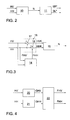
- Fig. 1 shows a motor vehicle 1 with a control unit 2.
- the control unit 2 is on the Motor vehicle arranged, but shown separately for reasons of clarity.
- the motor vehicle has two adjustable by means of an actuator, not shown Headlights 7 and 8, the optical light axis of the headlights 7 and 8 by means of the actuators to the motor vehicle 1 by the control unit 2
- Control commands SR * and SL * can be tilted up and / or down.
- a Design for such adjustment of headlights can e.g. the DE 100 44 512 A1 can be found.
- the control commands SR * and SL * can be the same or be independent of each other.
- the motor vehicle 1 has a front axle 3 and a rear axle 4.
- a sensor 5 and 6 for measuring the Height of the front axle 3 and the height of the rear axle 4 are provided.
- HV and HH for the height of the front axle 3 and Transfer the height of the rear axle 4 to the control unit 2.
- the control device 2 shows an exemplary embodiment of a control device 2.
- the control device 2 has one Pitch angle estimator 10 for calculating a value N for the pitch angle of the Motor vehicle 1 depending on the values HV and HH for the amount of Front axle 3 or the height of the rear axle 4.
- the control unit 2 also points a headlight controller 11 for calculating the control commands SR * and SL * in Dependence of the value N for the pitch angle of the motor vehicle 1.
- FIG 3 shows a preferred exemplary embodiment for a pitch angle estimator 10.
- This has a surface model 14 for determining the effects of unevenness Surface (on which the vehicle is moving) on the pitch angle, one Correction device 16 for correcting the value HV of the height of the front axle 3 and the value HH of the height of the rear axle 4 by the surface model 14 determined effects of the unevenness of the surface on the pitch angle and a pitch angle calculator 15.
- the correction device 16 has summation points 17 and 18, by means of which FHV and FHH output by the surface model are subtracted from the value HV of the height of the front axle 3 and the value HH of the height of the rear axle 4.
- the value HVK of the height of the front axle 3 corrected for the determined effects of the unevenness of the surface on the pitch angle and the value HHK of the height of the rear axle 4 corrected for the determined effect of the unevenness of the surface on the pitch angle are input variables in the pitch angle calculator 15 for calculating the value N for the pitch angle.
- Fig. 4 shows a particularly advantageous embodiment for the Surface model 14.
- the surface model 14 has a high-pass filter 20 for Filter the value HV of the height of the front axle 3 and to output a high-pass filtered Value GHV of the height of the front axle 3 and a high-pass filter 21 for Filter the value HH of the height of the rear axle 4 and to output a high-pass filtered GHH of the height of the rear axle 4.
- the respective cutoff frequency the high-pass filter is advantageously in a range between 0.1 Hz and 5 Hz, advantageously at substantially 1 Hz.
- FIG. 5 shows an alternative exemplary embodiment for a pitch angle estimator 10 to the advantageous exemplary embodiment in FIG. 3. This is based on a mathematical model 12 of the motor vehicle.
- the coefficients B + C are determined by the deviation dN of the vehicle inclination adapted.
- FIG. 6 shows an alternative embodiment to the embodiment in FIG. 2 for a control unit 2.
- the control unit 2 also has a pitch angle estimator 10 Calculation of a value N for the pitch angle of the motor vehicle 1 as a function the vehicle acceleration a.
- a Pitch angle calculator 25 can be used instead of the pitch angle estimator 10.
- the control unit 2 also has a filter 30 for generating a filtered value NG for the pitch angle of the motor vehicle 1 as a function of the value N for the Pitch angle of the motor vehicle 1.
- a filter 30 for generating a filtered value NG for the pitch angle of the motor vehicle 1 as a function of the value N for the Pitch angle of the motor vehicle 1.
- Exemplary embodiments for the adaptive filter 30 are explained in Fig. 7 and in Fig. 8.
- the control unit 2 also has a headlight control 11 for calculating the Control commands SR * and SL * depending on the filtered value NG for the Pitch angle of the motor vehicle 1.
- the filter 30 has an adaptive one Filter 35 for outputting a filtered value NG for the pitch angle and one Parameter calculator 36 for calculating at least one variable Parameters P1 of the adaptive filter 35 as a function of the value N for the Pitch angle and the filtered value NG for the pitch angle.
- the adaptive filter 35 can e.g. a low pass filter and the at least one variable parameter P1 one Limit frequency of the low-pass filter.
- the adaptive filter 35 can e.g. also a temporal averager and the at least one variable parameter P1 the Period of time over which the averager forms the mean.
- Fig. 8 shows a particularly advantageous embodiment for the filter 30.
- Das Filter 30 has an adaptive filter 37 for outputting a filtered value NG for the Pitch angle and a parameter calculator 38 for calculating at least one variable parameter P2 of the adaptive filter 37 as a function of the value N. for the pitch angle and the filtered value NG for the pitch angle.
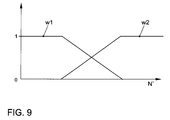
- the filter 30 also has a selector 39, by means of which a combined filtered value - in the present case denoted by NG1 - for the pitch angle proportionately to the value N (measured) of the pitch angle and the calculated NG1 value of the pitch angle in Dependence of a value N 'of the first time derivative of the pitch angle (FIG. 5). is imaginable.
- the value N 'of the first time derivative of the pitch angle is given by the Filter 30 in the specific exemplary embodiment by the adaptive filter 37 calculated.
- the adaptive filter 37 can e.g. a mathematical model according to WO 92/10377.
- NG w1 * NG1 + w2 * N
- w1 and w2 are weighting values dependent on the value N 'of the first time derivative of the pitch angle, the dependence of which on the value N' of the first time derivative of the pitch angle is shown in FIG. 9.
Landscapes
- Engineering & Computer Science (AREA)
- Mechanical Engineering (AREA)
- Lighting Device Outwards From Vehicle And Optical Signal (AREA)
- Non-Portable Lighting Devices Or Systems Thereof (AREA)
Abstract
Die Erfindung betrifft ein auf einer Oberfläche fahrbares Landfahrzeug, insbesondere ein Kraftfahrzeug (1), mit zumindest einem mittels eines Aktors einstellbaren Scheinwerfer (7, 8), wobei eine optische Lichtachse des Scheinwerfers mittels des Aktors in Abhängigkeit eines Wertes (N) des Nickwinkels des Landfahrzeugs relativ zu dem Landfahrzeug nach oben und/oder unten geneigt werden kann, und wobei ein Oberflächenmodell (14) zur Ermittlung von Einwirkungen von Unebenheiten der Oberfläche auf den Nickwinkel und eine Korrekturvorrichtung (16) zur Korrektur des Wertes (N) des Nickwinkels um die ermittelten Einwirkungen der Unebenheiten der Oberfläche auf den Nickwinkel vorgesehen ist. <IMAGE>The invention relates to a land vehicle that can be driven on a surface, in particular a motor vehicle (1), with at least one headlight (7, 8) that can be adjusted by means of an actuator, an optical light axis of the headlight being dependent on a value (N) of the pitch angle of the headlight Land vehicle can be inclined upwards and / or downwards relative to the land vehicle, and wherein a surface model (14) for determining the effects of unevenness in the surface on the pitch angle and a correction device (16) for correcting the value (N) of the pitch angle by determined effects of the unevenness of the surface on the pitch angle is provided. <IMAGE>
Description
Die Erfindung betrifft eine Scheinwerferanlage für ein Landfahrzeug, insbesondere ein Kraftfahrzeug, mit zumindest einem mittels eines Aktors einstellbaren Scheinwerfer, wobei eine optische Lichtachse des Scheinwerfers mittels des Aktors in Abhängigkeit eines Wertes des Nickwinkels des Landfahrzeugs relativ zu dem Landfahrzeug nach oben und/oder unten geneigt werden kann.The invention relates to a headlight system for a land vehicle, in particular a Motor vehicle, with at least one headlight adjustable by means of an actuator, an optical light axis of the headlamp depending on the actuator a value of the pitch angle of the land vehicle relative to the land vehicle can be inclined above and / or below.
Ein solcher mittels eines Aktors einstellbarer Scheinwerfer ist z.B. aus der DE 100 44 512 A1 bekannt. Zur Ansteuerung des Aktors ist gemäß der DE 100 44 512 A1 ein Fahrgeschwindigkeitssensor und ein Fahrzeughöhensensor vorgesehen, welcher entweder an einer linken oder einer rechten Aufhängung an entweder einem vorderen oder hinteren Abschnitt des Fahrzeugs zum Erfassen eines Abstands zwischen einer Achse und dem Fahrzeugkörper vorgesehen ist. Dabei werden Steuerdaten durch mindestens zwei oder mehr Steuerlinien mit unterschiedlichen Neigungen dargestellt.Such a headlight adjustable by means of an actuator is e.g. from the DE 100 44 512 A1 known. To control the actuator is according to the DE 100 44 512 A1 a vehicle speed sensor and a vehicle height sensor provided, which either on a left or a right suspension either a front or rear portion of the vehicle for sensing a Distance between an axis and the vehicle body is provided. In doing so Tax data through at least two or more tax lines with different Inclinations shown.
In der DE 196 28 405 A1 ist eine Vorrichtung zur Korrektur der Einstellung wenigstens eines Scheinwerfers eines Kraftfahrzeugs in Abhängigkeit von den Neigungsveränderungen der Fahrzeugkarosserie infolge von Laständerungen offenbart, wobei diese Vorrichtung Sensormittel zur Messung der Neigung der Fahrzeugkarosserie umfasst, sowie einen Filter mit langer Zeitkonstante, das ein gefiltertes Neigungssignal liefert, Mittel zur Erstellung der Einstellungskorrektur in Abhängigkeit vom Wert des gefilterten Neigungssignals, und wenigstens ein Stellglied, das durch die Mittel zur Korrekturerstellung gesteuert wird und mit einem Scheinwerfer des Fahrzeugs verbunden ist, wobei Erfassungsmittel vorgesehen sind, um den Unbeweglichkeits- oder Beweglichkeitszustand des Fahrzeugs in Abhängigkeit vom Inhalt des momentanen Neigungssignals zu bestimmen, und Schaltvorrichtungen, um auf die Mittel zur Korrekturerstellung ein gefiltertes Neigungssignal mit einer kürzeren Filterzeitkonstante als die besagte lange Zeitkonstante anzuwenden, wenn die Unbeweglichkeit des Fahrzeugs erfasst wird. In DE 196 28 405 A1 there is at least one device for correcting the setting a headlight of a motor vehicle depending on the Changes in inclination of the vehicle body due to changes in load disclosed said device comprising sensor means for measuring the inclination of the vehicle body comprises, as well as a filter with a long time constant, which a filtered inclination signal provides means for creating the adjustment correction depending on the value of the filtered inclination signal, and at least one actuator by the means for Correction is controlled and with a headlight of the vehicle is connected, wherein detection means are provided to the immobility or State of mobility of the vehicle depending on the content of the current one Determine inclination signal, and switching devices to the means for Correction creation of a filtered inclination signal with a shorter filter time constant than the long time constant to be used when the immobility of the Vehicle is detected.
Aus der Europäischen Patentschrift EP 0 355 539 B1 ist ein Verfahren zur Regelung der
Leuchtweite eines Fahrzeuges bekannt, bei dem beispielhaft über Niveaugeber die
relative Stellung der Fahrzeugkarosserie zu einer Achse, und damit die Lage der
Fahrzeugkarosserie zur Fahrbahn, ermittelt wird. Diese Signale werden durch eine
Mittelwertbildung gefiltert, wobei unterschiedliche Filterzeitkonstanten für die
Mittelwertbildung vorgesehen sind. Demgemäss kann die Regelung der Leuchtweite in
mindestens einem schnellen und mindestens einem langsamen Regelmodus
durchgeführt werden. Die Umschaltung zwischen den schnellen und langsamen
Regelmodi erfolgt in Abhängigkeit der gemessenen positiven oder negativen
Beschleunigung des Fahrzeuges. Ziel einer solchen dynamischen Leuchtweiteregelung
besteht darin, die Scheinwerferposition und damit die Leuchtweite vor dem Fahrzeug
entsprechend der Karosserieneigung durch Beladung, Beschleunigung und Bremsen
auszuregeln. Die Umschaltung auf langsame Regelmodi hat dabei zum Ziel, dass bei
kontinuierlicher Fahrt ohne wesentliche Karosserieneigungen Unebenheiten in der
Fahrbahn, z. B. Schlaglöcher, möglichst nicht ausgeregelt werden sollen. Dabei ist
gemäß der DE 198 24 862 A1 nachteilig, dass bei der längsbeschleunigungsabhängigen
Umschaltung der Regelmodi, z. B. auch bei einer kontinuierlichen Beschleunigung des
Fahrzeugs, bei der keine Neigungsänderung der Karosserie vorliegt, ein schneller
Regelmodus gewählt wird, so dass während einer solchen Beschleunigung in der
Fahrbahn auftretende Unebenheiten wie Schlaglöcher zu einer Verstellung der
Scheinwerferposition und damit zu einer Verstellung der Leuchtweite führen, wodurch
eine unruhige Bewegung der Hell-Dunkel-Grenze der Lichtverteilung der Scheinwerfer
erzeugt wird und eine Irritation des Fahrzeugführers herbeigeführt werden kann.
Aus der Europäischen Patentschrift EP 0 470 407 B1 ist eine Einrichtung zur Regelung
der Leuchtweite eines Kraftfahrzeuges bekannt, die nach dem gleichen Grundprinzip
arbeitet wie die Einrichtung zur Regelung der Leuchtweite gemäß der EP 0 355 539 B1,
wobei jedoch die Umschaltung der Regelmodi aufgrund eines Bremseingriffes erfolgt.
Dabei erweist es sich gemäß der DE 198 24 862 A1 bei dieser Einrichtung als nachteilig,
dass nur negative Beschleunigungen für die Umschaltung der Regelmodi berücksichtigt
werden.A device for regulation is known from European Patent EP 0 470 407 B1
the range of a motor vehicle known, based on the same basic principle
works like the device for regulating the lighting range according to
Aus der Europäischen Patentschrift EP 0 709 240 B1 ist eine dynamische
Leuchtweitenregelung bekannt, bei der die Veränderung der Lage der
Fahrzeugkarosserie allein aufgrund der Änderung der Längsbeschleunigung bzw.
Verzögerung des Fahrzeuges ermittelt und in eine Verstellung der Scheinwerfer
umgesetzt wird. Bei einem solchen System zur Regelung der Leuchtweite erweist es
sich gemäß der DE 198 24 862 A1 als nachteilig, dass die Lage der Fahrzeugkarosserie
zur Fahrbahn nur indirekt bestimmt werden kann und somit ein Fehler bei der
Leuchtweitenregelung auftritt.From the
Gemäß der DE 198 24 862 A1 wird zur Verbesserung der Regelung der Leuchtweite eines Fahrzeugs ein Verfahren zur Regelung der Leuchtweite von Fahrzeugscheinwerfern vorgeschlagen, bei dem die Regelung aufgrund der Lage der Karosserie zur Fahrbahn erfolgt und die Regelung mindestens einen schnellen und mindestens einen langsamen Regelmodus aufweist, wobei die Umschaltung von einem langsamen Regelmodus in einen schnellen Regelmodus abhängig von der Längsbeschleunigung des Fahrzeugs erfolgt, wobei die Umschaltung von einem langsamen Regelmodus in einen schnellen Regelmodus dann erfolgt, wenn der Betrag der Änderung der Längsbeschleunigung einen vorgegebenen Schwellwert überschreitet.According to DE 198 24 862 A1, to improve the regulation of the lighting range of a vehicle a method for regulating the headlight range of vehicle headlights Proposed the scheme based on the location of the body to the roadway and the regulation is at least a quick and at least has a slow control mode, the switch from a slow Control mode in a fast control mode depending on the longitudinal acceleration of the vehicle, the switchover from a slow control mode to a rapid control mode occurs when the amount of change in the Longitudinal acceleration exceeds a predetermined threshold.
Aus der DE 42 02 908 A1, DE 44 37 949 und der EP 0 847 895 B1 ist zudem bekannt,
eine Leuchtweitenreglung für ein Kraftfahrzeug in Abhängigkeit der Geschwindigkeit und
Beschleunigung des Kraftfahrzeugs zu parametrieren.DE 42 02 908 A1, DE 44 37 949 and
Es ist Aufgabe der Erfindung, eine Scheinwerferanlage für ein Landfahrzeug, insbesondere für ein Kraftfahrzeug, mit zumindest einem mittels eines Aktors einstellbaren Scheinwerfer, wobei eine optische Lichtachse des Scheinwerfers mittels des Aktors in Abhängigkeit eines Wertes des Nickwinkels des Landfahrzeugs relativ zu dem Landfahrzeug nach oben und/oder unten geneigt werden kann, zu verbessern. Dabei soll insbesondere die Reaktion einer solcher Scheinwerferanlage beim Überfahren von Schlaglöchern verbessert werden.It is an object of the invention to provide a headlight system for a land vehicle, in particular for a motor vehicle, with at least one by means of an actuator adjustable headlights, whereby an optical light axis of the headlights by means of of the actuator as a function of a value of the pitch angle of the land vehicle relative to the land vehicle can be tilted up and / or down to improve. In particular, the reaction of such a headlight system should Driving over potholes can be improved.
Vorgenannte Aufgabe wird durch eine Scheinwerferanlage für ein auf einer Oberfläche fahrbares Landfahrzeug, insbesondere ein Kraftfahrzeug, mit zumindest einem mittels eines Aktors einstellbaren Scheinwerfer gelöst, wobei eine optische Lichtachse des Scheinwerfers mittels des Aktors in Abhängigkeit eines Wertes des Nickwinkels des Landfahrzeugs relativ zu dem Landfahrzeug nach oben und/oder unten geneigt werden kann, und wobei ein Oberflächenmodell zur Ermittlung von Einwirkungen von Unebenheiten der Oberfläche auf den Nickwinkel vorgesehen ist. Vorteilhafterweise ist dabei zudem eine Korrekturvorrichtung zur Korrektur des Wertes des Nickwinkels um die ermittelten Einwirkungen der Unebenheiten der Oberfläche auf den Nickwinkel vorgesehen.The above task is performed by a headlamp system for one on a surface Mobile land vehicle, in particular a motor vehicle, with at least one means an actuator adjustable headlights solved, wherein an optical light axis of the Headlight by means of the actuator depending on a value of the pitch angle of the Land vehicle relative to the land vehicle to be tilted up and / or down can, and being a surface model for determining the effects of Surface unevenness on the pitch angle is provided. It is advantageous thereby also a correction device for correcting the value of the pitch angle the determined effects of the unevenness of the surface on the pitch angle intended.
Vorgenannte Aufgabe wird auch durch eine Scheinwerferanlage für ein Landfahrzeug, insbesondere ein Kraftfahrzeug, mit zumindest einem mittels eines Aktors einstellbaren Scheinwerfer gelöst, wobei eine optische Lichtachse des Scheinwerfers mittels des Aktors relativ zu dem Landfahrzeug nach oben und/oder unten geneigt werden kann, wobei ein adaptives Filter zur Ausgabe eines gefilterten Wertes des Nickwinkels in Abhängigkeit des Wertes des Nickwinkels vorgesehen ist, und wobei das Filter zumindest einen veränderlichen Parameter aufweist, der in Abhängigkeit des Wertes des Nickwinkels und des gefilterten Wertes des Nickwinkels verändert wird. Die optische Lichtachse des Scheinwerfers kann dabei in weiterhin vorteilhafter Ausgestaltung der Erfindung mittels des Aktors in Abhängigkeit des gefilterten Wertes des Nickwinkels des Landfahrzeugs relativ zu dem Landfahrzeug nach oben und/oder unten geneigt werden.The aforementioned task is also carried out by a headlight system for a land vehicle, in particular a motor vehicle, with at least one adjustable by means of an actuator Headlights solved, wherein an optical light axis of the headlights by means of Actuator can be tilted up and / or down relative to the land vehicle, an adaptive filter for outputting a filtered value of the pitch angle in Dependence of the value of the pitch angle is provided, and the filter has at least one variable parameter which is dependent on the value the pitch angle and the filtered value of the pitch angle is changed. The optical The light axis of the headlight can be in a further advantageous embodiment Invention by means of the actuator depending on the filtered value of the pitch angle of the Land vehicle relative to the land vehicle to be tilted up and / or down.
Vorgenannte Aufgabe wird auch durch eine Scheinwerferanlage für ein Landfahrzeug, insbesondere ein Kraftfahrzeug, mit zumindest einem mittels eines Aktors einstellbaren Scheinwerfer gelöst, wobei eine optische Lichtachse des Scheinwerfers mittels des Aktors relativ zu dem Landfahrzeug nach oben und/oder unten geneigt werden kann, und wobei die optische Lichtachse des Scheinwerfers mittels des Aktors in Abhängigkeit eines in Abhängigkeit eines Wertes der ersten zeitlichen Ableitung der Geschwindigkeit gebildeten Wertes relativ zu dem Landfahrzeug nach oben und/oder unten geneigt werden kann.The aforementioned task is also carried out by a headlight system for a land vehicle, in particular a motor vehicle, with at least one adjustable by means of an actuator Headlights solved, wherein an optical light axis of the headlights by means of Actuator can be tilted up and / or down relative to the land vehicle, and wherein the optical light axis of the headlamp is dependent on the actuator one depending on a value of the first time derivative of the speed formed value inclined upward and / or downward relative to the land vehicle can be.
Einwirkungen von Unebenheiten der Oberfläche auf den Nickwinkel im Sinne der Erfindung sind auch Einwirkungen auf Größen, mittels dessen der Nickwinkel berechnet wird. Eine Korrektur des Wertes des Nickwinkels um die ermittelten Einwirkungen der Unebenheiten der Oberfläche auf den Nickwinkel im Sinne der Erfindung umfasst nicht nur eine unmittelbare Korrektur des Wertes des Nickwinkels sondern auch eine mittelbare Korrektur des Wertes des Nickwinkels durch Korrektur von Werten mittels derer der Wert des Nickwinkels berechnet wird. So ist z.B. vorteilhafterweise bei einem Landfahrzeug mit eine Vorderachse und einer Hinterachse sowie Sensorik zur Bestimmung eines Wertes der Höhe der Vorderachse und eines Wertes der Höhe der Hinterachse vorgesehen, dass die Korrekturvorrichtung zur Korrektur des Wertes der Höhe der Vorderachse und des Wertes der Höhe der Hinterachse um die ermittelten Einwirkungen der Unebenheiten der Oberfläche auf den Nickwinkel ausgebildet ist. In vorteilhafter Ausgestaltung der Erfindung ist dabei ein Nickwinkelberechner zur Berechnung des Wertes für den Nickwinkel aus den um die ermittelten Einwirkungen der Unebenheiten der Oberfläche auf den Nickwinkel korrigierten Werten der Höhe der Vorderachse und der Höhe der Hinterachse vorgesehen.Effects of unevenness in the surface on the pitch angle in the sense of Invention are also actions on quantities by means of which the pitch angle is calculated becomes. A correction of the value of the pitch angle by the determined effects of the Unevenness of the surface on the pitch angle in the sense of the invention does not include only an immediate correction of the value of the pitch angle but also one indirect correction of the value of the pitch angle by correcting values using which is used to calculate the value of the pitch angle. For example, advantageously with one Land vehicle with a front axle and a rear axle as well as sensors for Determination of a value of the height of the front axle and a value of the height of the Rear axle provided that the correction device for correcting the value of the Height of the front axle and the value of the height of the rear axle around the determined Effects of the unevenness of the surface on the pitch angle is formed. In An advantageous embodiment of the invention is a pitch angle calculator Calculation of the value for the pitch angle from the effects of the determined Bumps on the surface corrected values of the height of the pitch angle Front axle and the height of the rear axle provided.
In weiterhin vorteilhafter Ausgestaltung der Erfindung ist ein adaptives Filter zur Ausgabe eines gefilterten Wertes des Nickwinkels in Abhängigkeit des Wertes des Nickwinkels vorgesehen, wobei das Filter zumindest einen veränderlichen Parameter aufweist, der in Abhängigkeit des Wertes des Nickwinkels und des gefilterten Wertes des Nickwinkels verändert wird.In a further advantageous embodiment of the invention, an adaptive filter for Output of a filtered value of the pitch angle depending on the value of the Pitch angle provided, the filter having at least one variable parameter has, depending on the value of the pitch angle and the filtered value the pitch angle is changed.
In weiterhin vorteilhafter Ausgestaltung der Erfindung kann die optische Lichtachse des Scheinwerfers mittels des Aktors zudem in Abhängigkeit des Wertes des Nickwinkels des Landfahrzeuges relativ zu dem Landfahrzeug nach oben und/oder unten geneigt werden.In a further advantageous embodiment of the invention, the optical light axis of the Headlights using the actuator also depending on the value of the pitch angle of the land vehicle is inclined upwards and / or downwards relative to the land vehicle become.
In weiterhin vorteilhafter Ausgestaltung der Erfindung ist das adaptive Filter ein Tiefpassfilter, wobei vorteilhafterweise der zumindest eine veränderliche Parameter eine Grenzfrequenz des Tiefpassfilters ist.In a further advantageous embodiment of the invention, the adaptive filter is on Low pass filter, the at least one variable parameter advantageously being a Limit frequency of the low pass filter is.
In weiterhin vorteilhafter Ausgestaltung der Erfindung ist das adaptive Filter ein zeitlicher Mittelwertbildner, wobei vorteilhafterweise der zumindest eine veränderliche Parameter die Zeitdauer ist, über die der Mittelwertbildner den Mittelwert bildet.In a further advantageous embodiment of the invention, the adaptive filter is a temporal one Averager, advantageously the at least one variable parameter is the length of time over which the averager forms the mean.
In weiterhin vorteilhafter Ausgestaltung der Erfindung ist das adaptive Filter ein mathematisches Modell oder eine neuronales Netz. Ein Ausführungsbeispiel für ein solches Modell ist z.B. in der WO 92/10377 offenbart.In a further advantageous embodiment of the invention, the adaptive filter is on mathematical model or a neural network. An embodiment for a such a model is e.g. disclosed in WO 92/10377.
In weiterhin vorteilhafter Ausgestaltung der Erfindung weist die Scheinwerferanlage einen Auswähler auf, mittels dessen ein kombinierter Wert für den Nickwinkel anteilig aus dem Wert des Nickwinkels, beispielsweise des gemessenen Nickwinkels, und dem berechneten Wert des Nickwinkels, der beispielsweise aus der Fahrzeugbeschleunigung ermittelt wird, bildbar ist. In weiterhin vorteilhafter Ausgestaltung der Erfindung wird die optische Lichtachse des Scheinwerfers mittels des Aktors in Abhängigkeit dieses kombinierten Wertes des Nickwinkels relativ zu dem Landfahrzeug nach oben und/oder unten geneigt. Die Bildung des kombinierten Werts für den Nickwinkel erfolgt in weiterhin vorteilhafter Ausgestaltung der Erfindung in Abhängigkeit eines Wertes der ersten zeitlichen Ableitung des Nickwinkels, der vorteilhafterweise mittels des adaptiven Filters ermittelt wird.In a further advantageous embodiment of the invention, the headlight system has a selector, by means of which a combined value for the pitch angle is proportional from the value of the pitch angle, for example the measured pitch angle, and the calculated value of the pitch angle, for example from the vehicle acceleration is determined, can be formed. In a further advantageous embodiment of the invention, the optical light axis of the headlight by means of the actuator depending on this combined value of the pitch angle relative to the land vehicle upwards and / or inclined down. The combined value for the pitch angle is formed in further advantageous embodiment of the invention depending on a value of first time derivative of the pitch angle, which advantageously by means of the adaptive Filters is determined.
Weitere Vorteile und Einzelheiten ergeben sich aus der nachfolgenden Beschreibung von Ausführungsbeispielen. Dabei zeigen:
- Fig. 1
- ein Kraftfahrzeug,
- Fig. 2
- ein Steuergerät,
- Fig. 3
- einen Nickwinkelschätzer,
- Fig. 4
- ein Oberflächenmodell,
- Fig. 5
- einen Nickwinkelschätzer,
- Fig. 6
- ein Steuergerät,
- Fig. 7
- ein Filter,
- Fig. 8
- ein Filter, und
- Fig. 9
- eine Implementierung für einen Auswähler.
- Fig. 1
- a motor vehicle,
- Fig. 2
- a control unit,
- Fig. 3
- a pitch angle estimator,
- Fig. 4
- a surface model,
- Fig. 5
- a pitch angle estimator,
- Fig. 6
- a control unit,
- Fig. 7
- a filter,
- Fig. 8
- a filter, and
- Fig. 9
- an implementation for a selector.
Fig. 1 zeigt ein Kraftfahrzeug 1 mit einem Steuergerät 2. Das Steuergerät 2 ist auf dem
Kraftfahrzeug angeordnet, jedoch aus Gründen der Übersichtlichkeit separat dargestellt.
Das Kraftfahrzeug weist zwei mittels je eines nicht dargestellten Aktors einstellbare
Scheinwerfer 7 und 8 auf, wobei die optische Lichtachse der Scheinwerfer 7 und 8
mittels der Aktoren zu dem Kraftfahrzeug 1 durch von dem Steuergerät 2 erzeugte
Steuerbefehle SR* und SL* nach oben und/oder unten geneigt werden kann. Eine
Ausführung zur derartigen Verstellung von Scheinwerfern kann z.B. der
DE 100 44 512 A1 entnommen werden. Die Steuerbefehle SR* und SL* können gleich
oder unabhängig voneinander sein.Fig. 1 shows a
Das Kraftfahrzeug 1 weist eine Vorderachse 3 und eine Hinterachse 4 auf. An der
Vorderachse 3 und der Hinterachse 4 sind jeweils ein Sensor 5 und 6 zum Messen der
Höhe der Vorderachse 3 und der Höhe der Hinterachse 4 vorgesehen. Von den
Sensoren 5 und 6 werden Werte HV und HH für die Höhe der Vorderachse 3 und die
Höhe der Hinterachse 4 an das Steuergerät 2 übertragen.The
Fig. 2 zeigt ein Ausführungsbeispiel für ein Steuergerät 2. Das Steuergerät 2 weist einen
Nickwinkelschätzer 10 zur Berechnung eines Wertes N für den Nickwinkel des
Kraftfahrzeugs 1 in Abhängigkeit von Werten HV und HH für die Höhe der
Vorderachse 3 bzw. die Höhe der Hinterachse 4 auf. Das Steuergerät 2 weist zudem
eine Scheinwerfersteuerung 11 zur Berechnung der Steuerbefehle SR* und SL* in
Abhängigkeit des Wertes N für den Nickwinkel des Kraftfahrzeugs 1 auf.2 shows an exemplary embodiment of a
Fig. 3 zeigt ein bevorzugtes Ausführungsbeispiel für einen Nickwinkelschätzer 10. Dieser
weist ein Oberflächen modell 14 zur Ermittlung von Einwirkungen von Unebenheiten der
Oberfläche (auf der sich das Kraftzeug bewegt) auf den Nickwinkel, eine
Korrekturvorrichtung 16 zur Korrektur des Wertes HV der Höhe der Vorderachse 3 und
des Wertes HH der Höhe der Hinterachse 4 um die durch das Oberflächenmodell 14
ermittelten Einwirkungen der Unebenheiten der Oberfläche auf den Nickwinkel und
einen Nickwinkelberechner 15 auf.3 shows a preferred exemplary embodiment for a
Die Korrekturvorrichtung 16 weist Summationspunke 17 und 18 auf, mittels derer von
dem Oberflächenmodell ausgegebene FHV und FHH vom dem Wert HV der Höhe der
Vorderachse 3 bzw. dem Wert HH der Höhe der Hinterachse 4 abgezogen werden. Der
so gebildete um die ermittelten Einwirkungen der Unebenheiten der Oberfläche auf den
Nickwinkel korrigierte Wert HVK der Höhe der Vorderachse 3 und der so gebildete um
die ermittelten Einwirkungen der Unebenheiten der Oberfläche auf den Nickwinkel
korrigierte Wert HHK der Höhe der Hinterachse 4 sind Eingangsgrößen in den
Nickwinkelberechner 15 zur Berechnung des Wertes N für den Nickwinkel. Der
Nickwinkel wird dabei gemäß
Fig. 4 zeigt ein besonders vorteilhaftes Ausführungsbeispiel für das
Oberflächen modell 14. Das Oberflächen modell 14 weist ein Hochpassfilter 20 zum
Filtern des Wertes HV der Höhe der Vorderachse 3 und zur Ausgabe eines hochpass-gefilterten
Wertes GHV der Höhe der Vorderachse 3 sowie ein Hochpassfilter 21 zum
Filtern des Wertes HH der Höhe der Hinterachse 4 und zur Ausgabe eines hochpass-gefilterten
Wertes GHH der Höhe der Hinterachse 4 auf. Die jeweilige Grenzfrequenz
der Hochpassfilter liegt vorteilhafterweise in einem Bereich zwischen 0,1Hz und 5Hz,
vorteilhafterweise bei wesentlichen 1 Hz.Fig. 4 shows a particularly advantageous embodiment for the
In besonders vorteilhafter Ausgestaltung weist das Oberflächenmodell 14 einen
Korrelator 22 auf, der von dem hochpass-gefilterten Wert GHV der Höhe der
Vorderachse 3 und dem hochpass-gefilterten Wert GHH der Höhe der Hinterachse 4 nur
die sich verändernden Anteile als unkorrelierten Wert FHV der Höhe der Vorderachse 3
und unkorrelierten Wert FHH der Höhe der Hinterachse 4 ausgibt, die im jeweils
anderen Wert nicht enthalten sind.In a particularly advantageous embodiment, the
Fig. 5 zeigt ein zu dem vorteilhaften Ausführungsbeispiel in Fig. 3 alternatives
Ausführungsbeispiel für einen Nickwinkelschätzer 10. Dieser basiert auf einem
mathematischen Modell 12 des Kraftfahrzeuges. Die Fahrzeugneigung N ist abhängig
von der Fahrzeugbeschleunigung a.
Beispielsweise:
For example:
Dabei werden die Koeffizienten B + C durch die Abweichung dN der Fahrzeugneigung adaptiert.The coefficients B + C are determined by the deviation dN of the vehicle inclination adapted.
Fig. 6 zeigt ein zu dem Ausführungsbeispiel in Fig. 2 alternatives Ausführungsbeispiel
für ein Steuergerät 2. Das Steuergerät 2 weist ebenfalls einen Nickwinkelschätzer 10 zur
Berechnung eines Wertes N für den Nickwinkel des Kraftfahrzeugs 1 in Abhängigkeit
der Fahrzeugbeschleunigung a auf. Anstelle des Nickwinkelschätzers 10 kann auch ein
Nickwinkelberechner 25 verwendet werden.FIG. 6 shows an alternative embodiment to the embodiment in FIG. 2
for a
Das Steuergerät 2 weist ferner ein Filter 30 zu Erzeugung eines gefilterten Wertes NG
für den Nickwinkel des Kraftfahrzeugs 1 in Abhängigkeit des Wertes N für den
Nickwinkel des Kraftfahrzeugs 1 auf. Ausführungsbeispiele für das adaptive Filter 30
sind in Fig. 7 und in Fig. 8 erläutert. The
Das Steuergerät 2 weist zudem eine Scheinwerfersteuerung 11 zur Berechnung der
Steuerbefehle SR* und SL* in Abhängigkeit des gefilterten Wertes NG für den
Nickwinkel des Kraftfahrzeugs 1 auf.The
Fig. 7 zeigt ein Ausführungsbeispiel für das Filter 30. Das Filter 30 weist ein adaptives
Filter 35 zur Ausgabe eines gefilterten Wertes NG für den Nickwinkel und einen
Parameterberechner 36 zur Berechnung mindestens eines veränderlichen
Parameters P1 des adaptiven Filters 35 in Abhängigkeit des Wertes N für den
Nickwinkel und des gefilterten Wertes NG für den Nickwinkel auf. Das adaptive Filter 35
kann z.B. ein Tiefpassfilter und der zumindest eine veränderliche Parameter P1 eine
Grenzfrequenz des Tiefpassfilters sein. Das adaptive Filter 35 kann z.B. auch ein
zeitlicher Mittelwertbildner und der zumindest eine veränderliche Parameter P1 die
Zeitdauer sein, über die der Mittelwertbildner den Mittelwert bildet.7 shows an exemplary embodiment for the
Fig. 8 zeigt ein besonders vorteilhaftes Ausführungsbeispiel für das Filter 30. Das
Filter 30 weist ein adaptives Filter 37 zur Ausgabe eines gefilterten Wertes NG für den
Nickwinkel und einen Parameterberechner 38 zur Berechnung mindestens eines
veränderlichen Parameters P2 des adaptiven Filters 37 in Abhängigkeit des Wertes N
für den Nickwinkel und des gefilterten Wertes NG für den Nickwinkel auf. Das Filter 30
weist zudem einen Auswähler 39 auf, mittels dessen ein kombinierter gefilterter Wert -
im vorliegenden Fall mit NG1 bezeichnet - für den Nickwinkel anteilig auf dem Wert N
(gemessen) des Nickwinkels und dem berechneten NG1 Wert des Nickwinkels in
Abhängigkeit eines Wertes N' der ersten zeitlichen Ableitung des Nickwinkels (Fig. 5).
bildbar ist. Der Wert N' der ersten zeitlichen Ableitung des Nickwinkels wird durch das
Filter 30 und zwar im konkreten Ausführungsbeispiel durch das adaptive Filter 37
berechnet. Das adaptive Filter 37 kann in diesem Fall z.B. ein mathematisches Modell
gemäß WO 92/10377 sein.Fig. 8 shows a particularly advantageous embodiment for the
Eine Implementierung für einen Auswähler 39 ist z.B.
Unter Höhe der Vorderachse und Höhe der Hinterachse in Sinne der Erfindung sind anstelle der absoluten Werte insbesondere - wie in der Regelungstechnik üblich - deren Variation um ihren Arbeitspunkt zu verstehen. Below the height of the front axle and the height of the rear axle in the sense of the invention instead of the absolute values in particular - as usual in control engineering - their Variation to understand your working point.
- 11
- Kraftfahrzeugmotor vehicle
- 22
- Steuergerätcontrol unit
- 33
- VorderachseFront
- 44
- Hinterachserear axle
- 5, 65, 6
- Sensorensensors
- 7,87.8
- Scheinwerferheadlights
- 1010
- NickwinkelschätzerPitch angle estimator
- 1111
- Scheinwerfersteuerungheadlight control
- 1212
- mathematisches Fahrzeugmodellmathematical vehicle model
- 1414
- Oberflächenmodelsurface Model
- 15, 25, 2615, 25, 26
- NickwinkelberechnerNickwinkelberechner
- 1616
- Korrekturvorrichtungcorrector
- 17, 18, 2717, 18, 27
- SummationspunkeSummation Punke
- 20, 2120, 21
- HochpassfilterHigh Pass Filter
- 2222
- Korrelatorcorrelator
- 3030
- Filterfilter
- 35, 3735, 37
- adaptives Filteradaptive filter
- 36, 3836, 38
- Parameterberechnerparameter calculator
- 3939
- Auswählerselector
- NN
- Wert N für den NickwinkelValue N for the pitch angle
- SR*, SL*SR *, SL *
- Steuerbefehlecommands
- HVHV
- Wert für die Höhe der VorderachseValue for the height of the front axle
- HHHH
- Wert für die Höhe der HinterachseValue for the height of the rear axle
- ll
- Abstand der Vorderachse von der HinterachseDistance of the front axle from the rear axle
- FHVRelief Society
- unkorrelierter Wert der Höhe der Vorderachseuncorrelated value of the height of the front axle
- FHHFHH
- unkorrelierter Wert der Höhe der Hinterachseuncorrelated value of the height of the rear axle
- HVKHVK
- korrigierter Wert der Höhe der Vorderachsecorrected value of the height of the front axle
- HHKHHK
- korrigierter Wert der Höhe der Hinterachse corrected value of the height of the rear axle
- GHVGHV
- hochpass-gefilterter Wert der Höhe der Vorderachsehigh-pass filtered value of the height of the front axle
- GHHGHH
- hochpass-gefilterter Wert der Höhe der Hinterachsehigh-pass filtered value of the height of the rear axle
- P1, P2P1, P2
- veränderliche Parameterchangeable parameters
- NG, NG1NG, NG1
- gefilterter Wert für den Nickwinkelfiltered value for the pitch angle
- N'N '
- Wert der ersten zeitlichen Ableitung des NickwinkelsValue of the first time derivative of the pitch angle
- w1, w2w1, w2
- WichtungswerteWeighting values
- aa
- Fahrzeugbeschleunigungvehicle acceleration
Claims (23)
Applications Claiming Priority (2)
| Application Number | Priority Date | Filing Date | Title |
|---|---|---|---|
| DE10309512A DE10309512A1 (en) | 2003-03-05 | 2003-03-05 | Headlight system for a land vehicle |
| DE10309512 | 2003-03-05 |
Publications (2)
| Publication Number | Publication Date |
|---|---|
| EP1454792A1 true EP1454792A1 (en) | 2004-09-08 |
| EP1454792B1 EP1454792B1 (en) | 2008-07-30 |
Family
ID=32797811
Family Applications (1)
| Application Number | Title | Priority Date | Filing Date |
|---|---|---|---|
| EP04002640A Expired - Lifetime EP1454792B1 (en) | 2003-03-05 | 2004-02-06 | Headlight arrangement for a land vehicle |
Country Status (3)
| Country | Link |
|---|---|
| EP (1) | EP1454792B1 (en) |
| AT (1) | ATE402844T1 (en) |
| DE (2) | DE10309512A1 (en) |
Cited By (1)
| Publication number | Priority date | Publication date | Assignee | Title |
|---|---|---|---|---|
| DE102019102326A1 (en) * | 2019-01-30 | 2020-07-30 | Automotive Lighting Reutlingen Gmbh | Motor vehicle headlights and method for operating a motor vehicle headlight |
Families Citing this family (1)
| Publication number | Priority date | Publication date | Assignee | Title |
|---|---|---|---|---|
| DE102021106782A1 (en) | 2021-03-19 | 2022-09-22 | HELLA GmbH & Co. KGaA | Computer-implemented method for headlight range adjustment |
Citations (6)
| Publication number | Priority date | Publication date | Assignee | Title |
|---|---|---|---|---|
| DE3129891A1 (en) * | 1980-07-31 | 1982-06-09 | Marchal Equip Auto | Device for the dynamic adjustment of the position of headlamps of a vehicle |
| EP0355539A2 (en) * | 1988-08-18 | 1990-02-28 | Hella KG Hueck & Co. | Device and method for controlling the lighting distance or the level of a vehicle |
| DE4026553A1 (en) * | 1990-08-22 | 1992-02-27 | Siemens Ag | DEVICE FOR HEADLIGHT CONTROL IN MOTOR VEHICLES |
| EP0825063A2 (en) * | 1996-08-22 | 1998-02-25 | Denso Corporation | Apparatus for automatically controlling a direction of an optical axis of a vehicle headlight |
| DE10128919A1 (en) * | 2000-06-15 | 2002-06-06 | Koito Mfg Co Ltd | Level compensation system for motor vehicle headlights |
| GB2373222A (en) * | 2001-03-13 | 2002-09-18 | Michael Weir | Predictive vehicle suspension |
-
2003
- 2003-03-05 DE DE10309512A patent/DE10309512A1/en not_active Withdrawn
-
2004
- 2004-02-06 EP EP04002640A patent/EP1454792B1/en not_active Expired - Lifetime
- 2004-02-06 DE DE502004007709T patent/DE502004007709D1/en not_active Expired - Lifetime
- 2004-02-06 AT AT04002640T patent/ATE402844T1/en not_active IP Right Cessation
Patent Citations (6)
| Publication number | Priority date | Publication date | Assignee | Title |
|---|---|---|---|---|
| DE3129891A1 (en) * | 1980-07-31 | 1982-06-09 | Marchal Equip Auto | Device for the dynamic adjustment of the position of headlamps of a vehicle |
| EP0355539A2 (en) * | 1988-08-18 | 1990-02-28 | Hella KG Hueck & Co. | Device and method for controlling the lighting distance or the level of a vehicle |
| DE4026553A1 (en) * | 1990-08-22 | 1992-02-27 | Siemens Ag | DEVICE FOR HEADLIGHT CONTROL IN MOTOR VEHICLES |
| EP0825063A2 (en) * | 1996-08-22 | 1998-02-25 | Denso Corporation | Apparatus for automatically controlling a direction of an optical axis of a vehicle headlight |
| DE10128919A1 (en) * | 2000-06-15 | 2002-06-06 | Koito Mfg Co Ltd | Level compensation system for motor vehicle headlights |
| GB2373222A (en) * | 2001-03-13 | 2002-09-18 | Michael Weir | Predictive vehicle suspension |
Cited By (1)
| Publication number | Priority date | Publication date | Assignee | Title |
|---|---|---|---|---|
| DE102019102326A1 (en) * | 2019-01-30 | 2020-07-30 | Automotive Lighting Reutlingen Gmbh | Motor vehicle headlights and method for operating a motor vehicle headlight |
Also Published As
| Publication number | Publication date |
|---|---|
| DE502004007709D1 (en) | 2008-09-11 |
| ATE402844T1 (en) | 2008-08-15 |
| EP1454792B1 (en) | 2008-07-30 |
| DE10309512A1 (en) | 2004-09-30 |
Similar Documents
| Publication | Publication Date | Title |
|---|---|---|
| DE60105478T2 (en) | Device for automatically adjusting the inclination of the light beam of a motor vehicle headlight | |
| DE102008025948A1 (en) | Method and device for controlling the emission of light at least one headlight of a vehicle | |
| DE69910461T2 (en) | Pitch angle calculation device for vehicle | |
| DE102011081354A1 (en) | Method for determining a roadway unevenness of a roadway section illuminated by at least one headlight of a vehicle and method for controlling a light emission of at least one headlight of a vehicle | |
| EP2748033A1 (en) | Method, control unit, and computer program product for setting a range of a headlamp of a vehicle | |
| DE112014006958T5 (en) | Headlight optical axis control device | |
| DE102007000145B4 (en) | Control system for an optical axis angle of a headlight | |
| DE102016206604B4 (en) | Control device and method for regulating a damper hardness of a vibration damper of a motor vehicle | |
| DE102013201850A1 (en) | Device for adjusting range of headlight of vehicle, is provided with adjustment of headlamps that is carried out for driving vehicle, based on determined topography and evaluation unit to analyze data generated by imaging device | |
| DE60035140T2 (en) | Device for adjusting the optical axis of a vehicle headlight | |
| DE60120314T2 (en) | Device for automatically controlling the optical axis of headlamps in relation to the angular position of the steering wheel | |
| DE102004058523B4 (en) | Method for carrying out a change in inclination of a motor vehicle | |
| EP2326533A1 (en) | Method and device for controlling vertical light-dark limits in headlights within a tilt range | |
| EP1454792B1 (en) | Headlight arrangement for a land vehicle | |
| EP1078814B1 (en) | Method and device for controlling the lighting distance of a vehicle | |
| DE102019208812B4 (en) | Controlled pitch inclination of a vehicle | |
| DE602004009139T2 (en) | Device for automatically adjusting the direction of an optical axis of a car headlight | |
| DE602004001032T2 (en) | Method to control the position of the light axis of a vehicle headlight. | |
| DE102013216903B4 (en) | Method and device for determining road quality | |
| DE10054606A1 (en) | Method and device for headlight range control of the headlights of a motor vehicle | |
| EP0962358A2 (en) | Method for adjusting the lighting distance of vehicle headlights | |
| EP1705061B1 (en) | Device and method to controll a bending-light adjustment angle in function of the road curvature and of the vehicle speed | |
| DE102023124352B3 (en) | Method for adapting a light distribution generated by a headlight system of a vehicle to a driving situation | |
| DE102014112444B4 (en) | Procedure for level regulation | |
| EP1749696B1 (en) | Method for adjustment of the lighting range of motor vehicle illumination devices and levelling system |
Legal Events
| Date | Code | Title | Description |
|---|---|---|---|
| PUAI | Public reference made under article 153(3) epc to a published international application that has entered the european phase |
Free format text: ORIGINAL CODE: 0009012 |
|
| AK | Designated contracting states |
Kind code of ref document: A1 Designated state(s): AT BE BG CH CY CZ DE DK EE ES FI FR GB GR HU IE IT LI LU MC NL PT RO SE SI SK TR |
|
| AX | Request for extension of the european patent |
Extension state: AL LT LV MK |
|
| 17P | Request for examination filed |
Effective date: 20050308 |
|
| AKX | Designation fees paid |
Designated state(s): AT BE BG CH CY CZ DE DK EE ES FI FR GB GR HU IE IT LI LU MC NL PT RO SE SI SK TR |
|
| 17Q | First examination report despatched |
Effective date: 20051031 |
|
| GRAP | Despatch of communication of intention to grant a patent |
Free format text: ORIGINAL CODE: EPIDOSNIGR1 |
|
| GRAS | Grant fee paid |
Free format text: ORIGINAL CODE: EPIDOSNIGR3 |
|
| GRAA | (expected) grant |
Free format text: ORIGINAL CODE: 0009210 |
|
| AK | Designated contracting states |
Kind code of ref document: B1 Designated state(s): AT BE BG CH CY CZ DE DK EE ES FI FR GB GR HU IE IT LI LU MC NL PT RO SE SI SK TR |
|
| REG | Reference to a national code |
Ref country code: GB Ref legal event code: FG4D Free format text: NOT ENGLISH |
|
| REG | Reference to a national code |
Ref country code: CH Ref legal event code: EP |
|
| REF | Corresponds to: |
Ref document number: 502004007709 Country of ref document: DE Date of ref document: 20080911 Kind code of ref document: P |
|
| REG | Reference to a national code |
Ref country code: IE Ref legal event code: FG4D Free format text: LANGUAGE OF EP DOCUMENT: GERMAN |
|
| PG25 | Lapsed in a contracting state [announced via postgrant information from national office to epo] |
Ref country code: NL Free format text: LAPSE BECAUSE OF FAILURE TO SUBMIT A TRANSLATION OF THE DESCRIPTION OR TO PAY THE FEE WITHIN THE PRESCRIBED TIME-LIMIT Effective date: 20080730 Ref country code: ES Free format text: LAPSE BECAUSE OF FAILURE TO SUBMIT A TRANSLATION OF THE DESCRIPTION OR TO PAY THE FEE WITHIN THE PRESCRIBED TIME-LIMIT Effective date: 20081110 Ref country code: PT Free format text: LAPSE BECAUSE OF FAILURE TO SUBMIT A TRANSLATION OF THE DESCRIPTION OR TO PAY THE FEE WITHIN THE PRESCRIBED TIME-LIMIT Effective date: 20081230 |
|
| PG25 | Lapsed in a contracting state [announced via postgrant information from national office to epo] |
Ref country code: FI Free format text: LAPSE BECAUSE OF FAILURE TO SUBMIT A TRANSLATION OF THE DESCRIPTION OR TO PAY THE FEE WITHIN THE PRESCRIBED TIME-LIMIT Effective date: 20080730 Ref country code: SI Free format text: LAPSE BECAUSE OF FAILURE TO SUBMIT A TRANSLATION OF THE DESCRIPTION OR TO PAY THE FEE WITHIN THE PRESCRIBED TIME-LIMIT Effective date: 20080730 Ref country code: BG Free format text: LAPSE BECAUSE OF FAILURE TO SUBMIT A TRANSLATION OF THE DESCRIPTION OR TO PAY THE FEE WITHIN THE PRESCRIBED TIME-LIMIT Effective date: 20081030 |
|
| REG | Reference to a national code |
Ref country code: IE Ref legal event code: FD4D |
|
| PG25 | Lapsed in a contracting state [announced via postgrant information from national office to epo] |
Ref country code: DK Free format text: LAPSE BECAUSE OF FAILURE TO SUBMIT A TRANSLATION OF THE DESCRIPTION OR TO PAY THE FEE WITHIN THE PRESCRIBED TIME-LIMIT Effective date: 20080730 Ref country code: EE Free format text: LAPSE BECAUSE OF FAILURE TO SUBMIT A TRANSLATION OF THE DESCRIPTION OR TO PAY THE FEE WITHIN THE PRESCRIBED TIME-LIMIT Effective date: 20080730 Ref country code: IE Free format text: LAPSE BECAUSE OF FAILURE TO SUBMIT A TRANSLATION OF THE DESCRIPTION OR TO PAY THE FEE WITHIN THE PRESCRIBED TIME-LIMIT Effective date: 20080730 |
|
| PG25 | Lapsed in a contracting state [announced via postgrant information from national office to epo] |
Ref country code: SK Free format text: LAPSE BECAUSE OF FAILURE TO SUBMIT A TRANSLATION OF THE DESCRIPTION OR TO PAY THE FEE WITHIN THE PRESCRIBED TIME-LIMIT Effective date: 20080730 Ref country code: RO Free format text: LAPSE BECAUSE OF FAILURE TO SUBMIT A TRANSLATION OF THE DESCRIPTION OR TO PAY THE FEE WITHIN THE PRESCRIBED TIME-LIMIT Effective date: 20080730 Ref country code: CZ Free format text: LAPSE BECAUSE OF FAILURE TO SUBMIT A TRANSLATION OF THE DESCRIPTION OR TO PAY THE FEE WITHIN THE PRESCRIBED TIME-LIMIT Effective date: 20080730 |
|
| PLBE | No opposition filed within time limit |
Free format text: ORIGINAL CODE: 0009261 |
|
| STAA | Information on the status of an ep patent application or granted ep patent |
Free format text: STATUS: NO OPPOSITION FILED WITHIN TIME LIMIT |
|
| 26N | No opposition filed |
Effective date: 20090506 |
|
| BERE | Be: lapsed |
Owner name: VOLKSWAGEN A.G. Effective date: 20090228 |
|
| PG25 | Lapsed in a contracting state [announced via postgrant information from national office to epo] |
Ref country code: MC Free format text: LAPSE BECAUSE OF NON-PAYMENT OF DUE FEES Effective date: 20090228 |
|
| REG | Reference to a national code |
Ref country code: CH Ref legal event code: PL |
|
| PG25 | Lapsed in a contracting state [announced via postgrant information from national office to epo] |
Ref country code: LI Free format text: LAPSE BECAUSE OF NON-PAYMENT OF DUE FEES Effective date: 20090228 Ref country code: CH Free format text: LAPSE BECAUSE OF NON-PAYMENT OF DUE FEES Effective date: 20090228 |
|
| PG25 | Lapsed in a contracting state [announced via postgrant information from national office to epo] |
Ref country code: SE Free format text: LAPSE BECAUSE OF FAILURE TO SUBMIT A TRANSLATION OF THE DESCRIPTION OR TO PAY THE FEE WITHIN THE PRESCRIBED TIME-LIMIT Effective date: 20081030 |
|
| PG25 | Lapsed in a contracting state [announced via postgrant information from national office to epo] |
Ref country code: BE Free format text: LAPSE BECAUSE OF NON-PAYMENT OF DUE FEES Effective date: 20090228 |
|
| PG25 | Lapsed in a contracting state [announced via postgrant information from national office to epo] |
Ref country code: AT Free format text: LAPSE BECAUSE OF NON-PAYMENT OF DUE FEES Effective date: 20090206 |
|
| PG25 | Lapsed in a contracting state [announced via postgrant information from national office to epo] |
Ref country code: GR Free format text: LAPSE BECAUSE OF FAILURE TO SUBMIT A TRANSLATION OF THE DESCRIPTION OR TO PAY THE FEE WITHIN THE PRESCRIBED TIME-LIMIT Effective date: 20081031 |
|
| PG25 | Lapsed in a contracting state [announced via postgrant information from national office to epo] |
Ref country code: LU Free format text: LAPSE BECAUSE OF NON-PAYMENT OF DUE FEES Effective date: 20090206 |
|
| PG25 | Lapsed in a contracting state [announced via postgrant information from national office to epo] |
Ref country code: HU Free format text: LAPSE BECAUSE OF FAILURE TO SUBMIT A TRANSLATION OF THE DESCRIPTION OR TO PAY THE FEE WITHIN THE PRESCRIBED TIME-LIMIT Effective date: 20090131 |
|
| PG25 | Lapsed in a contracting state [announced via postgrant information from national office to epo] |
Ref country code: TR Free format text: LAPSE BECAUSE OF FAILURE TO SUBMIT A TRANSLATION OF THE DESCRIPTION OR TO PAY THE FEE WITHIN THE PRESCRIBED TIME-LIMIT Effective date: 20080730 |
|
| PG25 | Lapsed in a contracting state [announced via postgrant information from national office to epo] |
Ref country code: CY Free format text: LAPSE BECAUSE OF FAILURE TO SUBMIT A TRANSLATION OF THE DESCRIPTION OR TO PAY THE FEE WITHIN THE PRESCRIBED TIME-LIMIT Effective date: 20080730 |
|
| PGFP | Annual fee paid to national office [announced via postgrant information from national office to epo] |
Ref country code: IT Payment date: 20120222 Year of fee payment: 9 |
|
| PGFP | Annual fee paid to national office [announced via postgrant information from national office to epo] |
Ref country code: GB Payment date: 20130228 Year of fee payment: 10 |
|
| GBPC | Gb: european patent ceased through non-payment of renewal fee |
Effective date: 20140206 |
|
| PG25 | Lapsed in a contracting state [announced via postgrant information from national office to epo] |
Ref country code: GB Free format text: LAPSE BECAUSE OF NON-PAYMENT OF DUE FEES Effective date: 20140206 |
|
| REG | Reference to a national code |
Ref country code: FR Ref legal event code: PLFP Year of fee payment: 13 |
|
| PG25 | Lapsed in a contracting state [announced via postgrant information from national office to epo] |
Ref country code: IT Free format text: LAPSE BECAUSE OF NON-PAYMENT OF DUE FEES Effective date: 20140206 |
|
| REG | Reference to a national code |
Ref country code: FR Ref legal event code: PLFP Year of fee payment: 14 |
|
| REG | Reference to a national code |
Ref country code: FR Ref legal event code: PLFP Year of fee payment: 15 |
|
| PGFP | Annual fee paid to national office [announced via postgrant information from national office to epo] |
Ref country code: DE Payment date: 20200229 Year of fee payment: 17 |
|
| PGFP | Annual fee paid to national office [announced via postgrant information from national office to epo] |
Ref country code: FR Payment date: 20200225 Year of fee payment: 17 |
|
| REG | Reference to a national code |
Ref country code: DE Ref legal event code: R119 Ref document number: 502004007709 Country of ref document: DE |
|
| PG25 | Lapsed in a contracting state [announced via postgrant information from national office to epo] |
Ref country code: DE Free format text: LAPSE BECAUSE OF NON-PAYMENT OF DUE FEES Effective date: 20210901 Ref country code: FR Free format text: LAPSE BECAUSE OF NON-PAYMENT OF DUE FEES Effective date: 20210228 |