EP1454716B1 - Pneumatisches Nagelgerät zum Befestigen von Elementen - Google Patents
Pneumatisches Nagelgerät zum Befestigen von Elementen Download PDFInfo
- Publication number
- EP1454716B1 EP1454716B1 EP04000693A EP04000693A EP1454716B1 EP 1454716 B1 EP1454716 B1 EP 1454716B1 EP 04000693 A EP04000693 A EP 04000693A EP 04000693 A EP04000693 A EP 04000693A EP 1454716 B1 EP1454716 B1 EP 1454716B1
- Authority
- EP
- European Patent Office
- Prior art keywords
- head
- container
- elements
- box
- guide
- Prior art date
- Legal status (The legal status is an assumption and is not a legal conclusion. Google has not performed a legal analysis and makes no representation as to the accuracy of the status listed.)
- Expired - Lifetime
Links
- 238000010304 firing Methods 0.000 claims abstract description 23
- 230000000295 complement effect Effects 0.000 claims abstract description 20
- 210000003323 beak Anatomy 0.000 claims description 10
- 230000014759 maintenance of location Effects 0.000 claims description 5
- 238000012423 maintenance Methods 0.000 description 6
- 230000007257 malfunction Effects 0.000 description 2
- 238000000034 method Methods 0.000 description 2
- 230000000903 blocking effect Effects 0.000 description 1
- 230000009189 diving Effects 0.000 description 1
- 238000000605 extraction Methods 0.000 description 1
- 230000000670 limiting effect Effects 0.000 description 1
- 238000012986 modification Methods 0.000 description 1
- 230000004048 modification Effects 0.000 description 1
Images

Classifications
-
- B—PERFORMING OPERATIONS; TRANSPORTING
- B25—HAND TOOLS; PORTABLE POWER-DRIVEN TOOLS; MANIPULATORS
- B25C—HAND-HELD NAILING OR STAPLING TOOLS; MANUALLY OPERATED PORTABLE STAPLING TOOLS
- B25C5/00—Manually operated portable stapling tools; Hand-held power-operated stapling tools; Staple feeding devices therefor
- B25C5/16—Staple-feeding devices, e.g. with feeding means, supports for staples or accessories concerning feeding devices
- B25C5/1665—Staple-feeding devices, e.g. with feeding means, supports for staples or accessories concerning feeding devices with means for preventing jamming or aiding unjamming within the drive channel
-
- B—PERFORMING OPERATIONS; TRANSPORTING
- B25—HAND TOOLS; PORTABLE POWER-DRIVEN TOOLS; MANIPULATORS
- B25C—HAND-HELD NAILING OR STAPLING TOOLS; MANUALLY OPERATED PORTABLE STAPLING TOOLS
- B25C1/00—Hand-held nailing tools; Nail feeding devices
- B25C1/001—Nail feeding devices
- B25C1/005—Nail feeding devices for rows of contiguous nails
Definitions
- the present invention relates to a pneumatic gun for fixing elements according to the preamble of claim 1.
- Such a pneumatic gun is known from US 5 297 713 .
- Pneumatically-actuated guns for driving fixing elements such as nails, staples and the like of various shapes and dimensions are widely used in various professional fields and sectors.
- These guns are generally constituted by a body that comprises the means for diving the fixing elements, an ergonomic handle, and a magazine of the fixing elements: such elements are usually available and loaded by being packed in stacks or sets and are fed one by one into a suitable firing channel through which they are expelled at high speed.
- Guns are known in which the fixing element magazine, which is generally straight and box-like, is connected detachably, for example at its opposite ends, respectively to the body of the gun and to the handle or is coupled thereto so as to slide or rotate about a fulcrum.
- these refinements allow to move or remove the magazine in order to access the firing channel and perform other maintenance actions, they require for this purpose a plurality of operations that are rather laborious, awkward and complicated and entail a considerable time expenditure.
- the aim of the present invention is to obviate the cited drawbacks, by providing a pneumatic gun in which it is possible to access easily, rapidly and effectively the fixing element firing channel in order to perform maintenance actions and restore the correct operation of the gun.
- an object of the present invention is to provide a pneumatic gun in which the fixing element magazine can be removed with a limited number of simple operations that can even be performed with just one hand in order to be reloaded or exchanged.
- Another object of the present invention is to provide a pneumatic gun having a structure that is simple, relatively easy to provide in practice, safe in use, effective in operation, and has a relatively low cost.
- the present pneumatic gun for fixing elements comprising a body provided with pneumatically-actuated means for expelling the fixing elements, a handle that protrudes from said body and a magazine for storing and individually feeding said elements, which is constituted by a box-like container provided with a sliding flap for inserting said elements, said body being provided with a working head for driving said elements that can be coupled to a complementary end head of said box-like container that is affected by an opening for the passage of said elements and is suitable to form, together with said head, a firing channel for said elements, wherin it comprises a guide that runs from said head to said handle and with which said box-like container is coupled slidingly so as to allow a manual translational motion of said magazine from a first active end position, in which said complementary head is adjacent to said head, allowing the expulsion of said elements through said firing channel, to a second position, in which said complementary head is substantially spaced from said head in order to allow access to said firing channel.
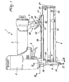
- the reference numeral 1 generally designates a pneumatic gun for fixing elements according to the invention.
- the pneumatic gun of the type designed to be used easily with a single hand, comprises a body 2 from which a straight ergonomic handle 3 extends at right angles.
- the body 2 is substantially cylindrically symmetrical and is provided with means for expelling the fixing elements; the gun further comprises a magazine 4 for storing and individually feeding such elements, which are constituted for example by nails of various shapes and sizes.
- the means for expelling the fixing elements are preferably of the type with a pneumatic striker and are not shown in detail in the figures because they are known.
- the handle 3 of the gun has, at its free end, a substantially perpendicular extension 5 and encloses a compressed-air tank for supplying the fixing element firing means.
- buttons 6 for actuating the expulsion means; such button allows, every time the operator applies manual pressure, to activate in a pulsed manner the striker in order to eject a single fixing element.
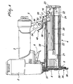
- the fixing elements are expelled one by one through a suitable firing channel 7 formed by two mutually opposite notches provided respectively in an elongated head 8, which is coupled monolithically to the body 2 of the gun so as to form a sort of beak, and a complementary head 9, which is connected rigidly to the fixing element magazine 4 for example by means of screws 10.
- the magazine 4 is constituted by a box-like container 11 that is substantially shaped like a parallelepiped that is elongated and open along one side, so as to form a compartment for inserting the fixing elements; the box-like container 11 has a side that forms two mutually opposite longitudinal ribs 12 and has, in order to block the opening along the side, a sliding flap 13 that is associated with a fastening device 14 that is adapted to keep the magazine 4 closed during normal use of the gun.
- the box-like container 11 is affected, at the end that lies opposite with respect to the end for connection to the complementary head 9, by a sort of window 15, in which a contoured tooth 17 is inserted and locked for example by means of screws 16; the tooth protrudes outward and has a substantially triangular transverse cross-section.
- the complementary head 9 has a narrow and elongated passage opening 18 for the fixing elements that leads to the firing channel 7; the passage opening 18 is provided so that it is substantially universal, since it has a plurality of wider regions 19 that allow the exit of fixing elements (particularly of the heads, in the case of nails as in this instance) of different sizes (reference should be made to Figure 6 in this regard).
- the box-like container 11 and the sliding flap 13 have respective mutually opposite internal walls affected by corresponding longitudinal grooves 20 that are connected to the wider regions 19 of the passage opening 18 for the fixing elements ( Figure 7 ); such grooves 20 constitute a sort of guide for the advancement of the fixing elements inside the magazine 4 toward the passage opening 18.
- a pusher 21 ( Figures 4 and 5 ) is guided so that it can slide longitudinally inside the magazine 4 and allows the advancement of the fixing elements along the grooves 20 so that they are arranged one after the other at the firing channel 7 in order to be expelled.
- the pusher 21 is associated with a first end of a helical spring 22 whose second end abuts against an abutment surface 23 provided in a plate 24 that is rigidly coupled (by way of screws 25) to the rear end of the flap 13.
- the fastening device 14 comprises a sort of rocker 26 that is articulated, substantially at the centerline, to a pivot 27, which in turn is supported transversely and at its ends in the plate 24 ( Figure 3 ).
- the rocker 26 has a first end 28 for manual actuation and a second end that forms a sort of lug 29 that is adapted to engage by straddling a respective pin 30 that is transversely rigidly coupled, at its ends, to the outside wall of the box-like container 11.
- the first end 28 for manual actuation forms a substantially cylindrical raised portion 31 that is coupled to one end of a helical spring 32 whose opposite end is inserted with interference in a hole 33 formed in the plate 24.
- the rocker 26 accordingly can rotate manually between a first stable angular position, in which the lug 29 engages by straddling the pin 30 so as to prevent the sliding of the flap 13 and the opening of the magazine 4, and a second angular position, which is determined by the manual pressure of the operator on the first end 28 and is contrasted by the loading of the spring 32. In this second angular position, the lug 29 is disengaged from the pin 30, allowing the flap 13 to slide and accordingly allowing the magazine 4 to open.
- the safety device 34 comprises a lamina 35 that is guided so that it can slide parallel to the surface of the head 8 and has an end provided with a sort of hood 36 for abutment on the surface being worked, and is associated at its opposite end with one end of a contrast spring 37; the other end of the contrast spring 37 is inserted in a suitable recess formed in the surface of the body 2 of the gun.
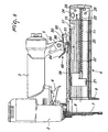
- the gun comprises a straight guide 38 that runs from the head 8 to the extension 5 of the handle 3 and in which the box-like container 11 is coupled slidingly, so as to allow the manual translational motion of the magazine 4 from a first active end position, in which the complementary head 9 is adjacent to the head 8, allowing the correct expulsion of the fixing elements through the firing channel 7, to a second position, in which the complementary head 9 is substantially spaced from the head 8.
- the operator can access freely and safely the firing channel 7, for example to remove a badly positioned element that obstructs the expulsion of the subsequent elements, or more generally to perform gun maintenance actions.
- the guide 38 is preferably constituted by a profiled element, which forms a first end 39 for fixing by way of front screws 40 to the head 8 and a second end 41 that is adapted for connection to the extension 5 of the handle 3: in the specific case, the guide 38 forms, on the back 42 and at the second end 41, a sort of eye 43 by way of which it is coupled to the extension 5 by screw means 44 (for example a through screw with a locking nut).
- the internal surface 45 of the profiled element is affected by a longitudinal slot 46 that is open at the rear and along which the box-like container 11 can slide.
- the longitudinal slot 46 of the guide has a substantially T-shaped transverse cross-section ( Figures 6 and 7 ) and forms two squared guides 47 along which the ribs 12 of the box-like container 11 engage slidingly.
- the guide 38 is provided with means 48 for the quick manual locking and release of the translational motion of the box-like container 11 along the longitudinal slot 46.
- the locking and release means 48 are associated with a safety closure 49 that is adapted to prevent the accidental extraction of the box-like container 11 from the guide 38.
- the locking and release means 48 comprise a lever 50 which is pivoted, at its centerline, to a pivot 51, whose ends are engaged in respective opposite coaxial holes 52 that are formed transversely in the eye 43 and in a lug 53 on the back 42 of the guide 38.
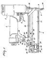
- the lever 50 has a first end portion 54 for manual actuation and a second end portion that forms a sort of beak 55 that has a rounded profile and is adapted to abut against the contoured tooth 17 that is monolithic with the box-like container 11; elastic means 56 are interposed between the first end portion 54 and the back 42 of the guide 38 and are preferably constituted by a coiled spring wound around the pivot 51.
- the lever 50 can rotate manually from a first stable angular position, ensured by the elastic action of the coiled spring 56, in which the beak 55 engages the contoured tooth 17, locking the sliding of the box-like container 11 along the guide 38 ( Figure 4 ), to a second angular position, obtained by pressing manually on the first end portion 54, in which the beak 55 is substantially disengaged from the tooth 17, allowing the box-like container 11 to slide along the guide 38 ( Figure 5 ), even to the extent of producing complete disengagement of the ribs 12 from the respective guides 47.
- the safety closure 49 for preventing unwanted accidental disengagement of the box-like container 11 is constituted by an insert 57 that is engaged detachably in a sort of open pocket 58, which is rigidly coupled to the guide 38 along one side ( Figure 2 ): the insert 57 is adapted to abut by interference against an appropriately provided retention protrusion 59 that is provided along the outer wall of the box-like container 11, so as to prevent the sliding thereof along the guide 38 beyond a preset position.
- the retention protrusion 59 can be constituted for example by the head of a screw that is screwed into a respective threaded hole formed in the outer wall.
- the method of use of the pneumatic gun according to the invention is intuitive. If it is necessary, during use of the gun, to access the head 8, the complementary head 9 and the firing channel 7 freely and easily in order to perform maintenance actions, for example to remove badly positioned or jammed fixing elements that obstruct the passage opening 18 and the firing channel 7, an appropriate pressure (such as to overcome the action of the coiled spring 56) is applied manually to the first end portion 54 of the lever 50 toward the back 42 of the guide 38. The lever 50 is consequently rotated from the first stable angular position to the second angular position, so as to disengage the beak 55 from the contoured tooth 17.
- an appropriate pressure such as to overcome the action of the coiled spring 56
- the magazine 4 By acting on the lever 50, the magazine 4 can be moved easily along the guide 38, so as to disengage the complementary head 9 from the head 8 in order to perform any gun maintenance operation, even with a single hand. Moreover, the magazine can be extracted rapidly and handily, after extracting the insert 57, in order to be reloaded by way of fixing elements or to be replaced with another one.
Landscapes
- Engineering & Computer Science (AREA)
- Mechanical Engineering (AREA)
- Toys (AREA)
- Coating Apparatus (AREA)
- Portable Nailing Machines And Staplers (AREA)
- Actuator (AREA)
Claims (8)
- Luftdruckpistole für Befestigungselemente, mit einem Körper (2), der mit pneumatisch betätigten Mitteln zum Ausstoßen der Elemente versehen ist, einer von dem Körper (2) vorstehenden Handhabe (3) und einem Magazin (4) zum Speichern und einzelnen Zuführen der Befestigungselemente, das aus einem schachtelartigen Behälter (11) besteht, der mit einer verschieblichen Klappe (13) zum Einlegen der Elemente versehen ist, wobei der Körper (2) mit einem Arbeitskopf (8) zum Treiben der Elemente versehen ist, der mit einem komplementären Endkopf (9) des schachtelartigen Behälters (11) verbunden werden kann, der mit einer Öffnung (18) zum Hindurchlauf der Elemente ausgestattet ist und zusammen mit dem Kopf (8) einen Schusskanal (7) für die Elemente bilden kann, dadurch gekennzeichnet, dass die Pistole eine Führung (38) umfasst, die von dem Kopf (8) zu der Handhabe (3) verläuft, und mit welcher der schachtelartige Behälter (11) verschieblich verbunden ist, um damit eine manuelle Translationsbewegung des Magazins (4) aus einer ersten aktiven Endposition, in welcher der komplementäre Kopf (9) an den Kopf (8) angrenzt und das Ausstoßen der Elemente durch den Schusskanal (7) hindurch ermöglicht, in eine zweite Endposition zuzulassen, in welcher der komplementäre Kopf (9) wesentlich von dem Kopf (8) beabstandet ist, um einen Zugang zu dem Schusskanal (7) zu ermöglichen.
- Pistole nach Anspruch 1, dadurch gekennzeichnet, dass die Führung (38) aus einem Profilelement besteht, das im Wesentlichen rechtwinkelig zu dem Kopf (8) angeordnet ist und einen Längsschlitz (46) bildet, entlang dem der Behälter (11) verschieblich in Eingriff gebracht wird.
- Pistole nach den Ansprüchen 1 und 2, dadurch gekennzeichnet, dass die Führung (38) mit Mitteln (48) zum schnellen manuellen Verriegeln und zum Freigeben der Translationsbewegung des schachtelartigen Behälters (11) versehen ist.
- Pistole nach einem oder mehreren der vorhergehenden Ansprüche, dadurch gekennzeichnet, dass die Verriegelungs- und Freigabemittel (48) einem Sicherheitsverschluss (49) zugeordnet sind, welcher die Translationsbewegung des schachtelartigen Behälters (11) über eine voreingestellte Position hinaus und sein zufälliges Außereingriffkommen mit der Führung (38) verhindern kann.
- Pistole nach einem oder mehreren der vorhergehenden Ansprüche, dadurch gekennzeichnet, dass die Verriegelungs- und Freigabemittel (48) einem Hebel (50) umfassen, der im Wesentlichen an seiner Mittellinie drehbar an der Führung (38) befestigt ist und einen ersten Endabschnitt (54) zur Betätigung und einen zweiten Endabschnitt aufweist, der eine Art eines Schnabels (55) bildet, der gegen einen konturierten Zahn (17) anliegen kann, der mit dem schachtelartigen Behälter (11) monolithisch ist, wobei zwischen dem ersten Endabschnitt (54) und der Führung (38) elastische Mittel (56) eingefügt sind und sich der Hebel (50) manuell aus einer durch die elastischen Mittel (56) bereitgestellten, ersten stabilen Winkelposition zum Sperren der Verschiebebewegung des schachtelartigen Behälters (11), in welchem der Schnabel (55) an dem konturierten Zahn (17) in Eingriff steht, in eine zweite Winkelposition drehen lässt, in welcher der Schnabel (55) im Wesentlichen außer Eingriff mit dem Zahn (17) gebracht ist, wodurch der schachtelartigen Behälter (11) frei entlang der Führung (38) gleiten kann.
- Pistole nach einem oder mehreren der vorhergehenden Ansprüche, dadurch gekennzeichnet, dass der Sicherheitsverschluss (49) von einem Einsatz (57) gebildet wird, der lösbar in einer jeweiligen Tasche (58) in Eingriff steht, die in der Führung (38) vorgesehen ist und gegen einen Haltevorsprung (59) anliegen kann, der entlang dem schachtelartigen Behälter (11) vorgesehen ist.
- Pistole nach einem oder mehreren der vorhergehenden Ansprüche, dadurch gekennzeichnet, dass der Längsschlitz (46) der Führung (38) einen im Wesentlichen T-förmigen Querschnitt aufweist.
- Pistole nach einem oder mehreren der vorhergehenden Ansprüche, dadurch gekennzeichnet, dass die Führung (38) auf der Rückseite (42) an einem Ende (41) eine Öse (43) zur lösbaren Verbindung mit Hilfe von Schraubenmitteln (44) an einer Verlängerung (5) der Handhabe (3) bildet.
Applications Claiming Priority (2)
| Application Number | Priority Date | Filing Date | Title |
|---|---|---|---|
| ITBO20030105 | 2003-02-28 | ||
| IT000105A ITBO20030105A1 (it) | 2003-02-28 | 2003-02-28 | Pistola pneumatica per elementi di fissaggio. |
Publications (2)
| Publication Number | Publication Date |
|---|---|
| EP1454716A1 EP1454716A1 (de) | 2004-09-08 |
| EP1454716B1 true EP1454716B1 (de) | 2008-05-21 |
Family
ID=32800652
Family Applications (1)
| Application Number | Title | Priority Date | Filing Date |
|---|---|---|---|
| EP04000693A Expired - Lifetime EP1454716B1 (de) | 2003-02-28 | 2004-01-15 | Pneumatisches Nagelgerät zum Befestigen von Elementen |
Country Status (5)
| Country | Link |
|---|---|
| US (1) | US7070082B2 (de) |
| EP (1) | EP1454716B1 (de) |
| AT (1) | ATE396012T1 (de) |
| DE (1) | DE602004013859D1 (de) |
| IT (1) | ITBO20030105A1 (de) |
Families Citing this family (26)
| Publication number | Priority date | Publication date | Assignee | Title |
|---|---|---|---|---|
| USD498127S1 (en) * | 2003-11-19 | 2004-11-09 | Porter-Cable Corporation | Pneumatic fastener |
| USD521837S1 (en) * | 2004-02-26 | 2006-05-30 | Huading Zhang | Electric nailer/stapler |
| JP4569252B2 (ja) * | 2004-10-08 | 2010-10-27 | マックス株式会社 | 動力駆動釘打機 |
| USD512621S1 (en) * | 2005-01-11 | 2005-12-13 | Eastway Fair Company Limited | Brad nailer |
| USD517886S1 (en) * | 2005-01-11 | 2006-03-28 | Eastway Fair Company Limited | Finish stapler |
| USD512622S1 (en) * | 2005-01-11 | 2005-12-13 | Eastway Fair Company Limited | Straight finish nailer |
| US7225960B2 (en) * | 2005-06-07 | 2007-06-05 | Hsiu-Chiang Chen | Locking device for magazine of staplers |
| US20070095875A1 (en) * | 2005-11-03 | 2007-05-03 | Pneutools, Incorporated | Single-blow pneumatic nailing tool |
| TW200823018A (en) * | 2006-11-30 | 2008-06-01 | Samson Power Tool Co Ltd | Nozzle assembly for nail-roll type nailer |
| JP4678375B2 (ja) * | 2007-01-31 | 2011-04-27 | 日立工機株式会社 | 打込機 |
| DE102008000831A1 (de) * | 2008-03-26 | 2009-10-01 | Hilti Aktiengesellschaft | Setzgerät |
| US20110278342A1 (en) * | 2010-05-17 | 2011-11-17 | De Poan Pneumatic Corp. | Nail gun with improved attachable and detachable magazine assembly |
| US10300589B2 (en) * | 2012-03-02 | 2019-05-28 | Arrow Fastener Company, Llc | Fastening tool assembly |
| FR2993810B1 (fr) * | 2012-07-25 | 2014-07-11 | Illinois Tool Works | Outil de fixation par tir indirect, a support de detente anti-tir |
| EP3253534B1 (de) | 2015-02-06 | 2020-05-06 | Milwaukee Electric Tool Corporation | Gasfederbetriebener befestigungstreiber |
| US11325235B2 (en) | 2016-06-28 | 2022-05-10 | Black & Decker, Inc. | Push-on support member for fastening tools |
| US11267114B2 (en) | 2016-06-29 | 2022-03-08 | Black & Decker, Inc. | Single-motion magazine retention for fastening tools |
| US11400572B2 (en) | 2016-06-30 | 2022-08-02 | Black & Decker, Inc. | Dry-fire bypass for a fastening tool |
| US10987790B2 (en) | 2016-06-30 | 2021-04-27 | Black & Decker Inc. | Cordless concrete nailer with improved power take-off mechanism |
| US10926385B2 (en) | 2017-02-24 | 2021-02-23 | Black & Decker, Inc. | Contact trip having magnetic filter |
| MX2020008375A (es) | 2018-02-08 | 2020-09-25 | Yissum Res Dev Co Of Hebrew Univ Jerusalem Ltd | Compuestos de heteroarilo, composiciones farmaceuticas de los mismos y su uso terapeutico. |
| BR112021024330A2 (pt) | 2019-06-03 | 2022-01-11 | Biotheryx Inc | Sais cristalinos não higroscópicos de um composto de pirazol, e composições farmacêuticas e uso dos mesmos |
| USD958625S1 (en) * | 2019-11-11 | 2022-07-26 | Zhejiang Prulde Electric Appliance Co., Ltd. | Nail gun |
| USD956500S1 (en) * | 2019-11-11 | 2022-07-05 | Zhejiang Prulde Electric Appliance Co., Ltd. | Nail gun |
| USD956502S1 (en) * | 2019-11-11 | 2022-07-05 | Zhejiang Prulde Electric Appliance Co., Ltd. | Nail gun |
| US12162125B2 (en) | 2020-10-30 | 2024-12-10 | Milwaukee Electric Tool Corporation | Powered fastener driver |
Family Cites Families (8)
| Publication number | Priority date | Publication date | Assignee | Title |
|---|---|---|---|---|
| US3437250A (en) * | 1966-04-07 | 1969-04-08 | Fastener Corp | Fastener driving tool |
| US4304349B1 (en) * | 1979-10-09 | 1996-02-27 | Duo Fast Cord | Fastener driving tool |
| US4463888A (en) * | 1981-04-22 | 1984-08-07 | Duo-Fast Corporation | Fastener driving tool |
| CA1175201A (en) * | 1981-10-20 | 1984-10-02 | Siegfried F. Figge | Magazine assembly for coil nails |
| IT1225354B (it) * | 1988-12-02 | 1990-11-13 | Fasco Spa | Caricatore per pistola chiodatrice ad aria compressa |
| US5297713A (en) * | 1993-03-31 | 1994-03-29 | Stanley-Bostitch, Inc. | Rear load magazine assembly |
| US5653371A (en) * | 1995-09-14 | 1997-08-05 | Hou; Chang Feng-Mei | Magazine for power nail guns |
| IT1299814B1 (it) * | 1998-01-09 | 2000-04-04 | Fasco Spa | Fissatrice ad aria compressa. |
-
2003
- 2003-02-28 IT IT000105A patent/ITBO20030105A1/it unknown
-
2004
- 2004-01-15 AT AT04000693T patent/ATE396012T1/de not_active IP Right Cessation
- 2004-01-15 EP EP04000693A patent/EP1454716B1/de not_active Expired - Lifetime
- 2004-01-15 DE DE602004013859T patent/DE602004013859D1/de not_active Expired - Lifetime
- 2004-02-25 US US10/786,801 patent/US7070082B2/en not_active Expired - Fee Related
Also Published As
| Publication number | Publication date |
|---|---|
| US7070082B2 (en) | 2006-07-04 |
| DE602004013859D1 (de) | 2008-07-03 |
| EP1454716A1 (de) | 2004-09-08 |
| ITBO20030105A1 (it) | 2004-09-01 |
| US20040169057A1 (en) | 2004-09-02 |
| ATE396012T1 (de) | 2008-06-15 |
Similar Documents
| Publication | Publication Date | Title |
|---|---|---|
| EP1454716B1 (de) | Pneumatisches Nagelgerät zum Befestigen von Elementen | |
| US3688966A (en) | Magazine and feed assembly for a fastener-driving tool | |
| US4804127A (en) | Fastener driving gun | |
| EP0218778B1 (de) | Tragbares Eintreibgerät für Befestigungsmittel | |
| TWI515090B (zh) | 具有空包彈封鎖裝置的緊固件驅動器 | |
| US4821938A (en) | Powder-actuated fastener driving tool | |
| US5071052A (en) | Surgical fastening apparatus with activation lockout | |
| US3949924A (en) | Surgical stapling instrument | |
| DE60219874T2 (de) | Sperrmechanismus für ein Gerät zum Eintreiben von Befestigungsmitteln | |
| US3797723A (en) | Fastener-driving tool | |
| KR920003124B1 (ko) | 뼈 스테플러 | |
| US4367837A (en) | Tape magazine feed apparatus for head driven fasteners | |
| EP0828587B1 (de) | Zuführvorrichtung für ein befestigungsmitteleintreibgerät | |
| EP2781307B1 (de) | Betätigungssperre für ein Befestigungsmitteleintreibwerkzeug | |
| US20050001007A1 (en) | Pneumatic nailer | |
| EP2669058A2 (de) | Elektrowerkzeug mit Federkringelauslösungsaktuator | |
| JPH04365567A (ja) | 釘打機におけるプッシャ装置 | |
| EP0928666A2 (de) | Druckluftnagelgerät | |
| US4114792A (en) | Powder actuated tool | |
| EP2660010B1 (de) | Befestigungswerkzeuganordnung | |
| US3623646A (en) | Fastener-inserting machine | |
| US6092711A (en) | Magazine for compressed-air nail firing tool | |
| US4162033A (en) | Powder actuated tool | |
| IE41492B1 (en) | Explosive-powered fastener-driving tool | |
| US4432484A (en) | Tool for driving metal fasteners in a frame and setting its rear closing panel |
Legal Events
| Date | Code | Title | Description |
|---|---|---|---|
| PUAI | Public reference made under article 153(3) epc to a published international application that has entered the european phase |
Free format text: ORIGINAL CODE: 0009012 |
|
| AK | Designated contracting states |
Kind code of ref document: A1 Designated state(s): AT BE BG CH CY CZ DE DK EE ES FI FR GB GR HU IE IT LI LU MC NL PT RO SE SI SK TR |
|
| AX | Request for extension of the european patent |
Extension state: AL LT LV MK |
|
| 17P | Request for examination filed |
Effective date: 20050302 |
|
| AKX | Designation fees paid |
Designated state(s): AT BE BG CH CY CZ DE DK EE ES FI FR GB GR HU IE IT LI LU MC NL PT RO SE SI SK TR |
|
| GRAP | Despatch of communication of intention to grant a patent |
Free format text: ORIGINAL CODE: EPIDOSNIGR1 |
|
| GRAS | Grant fee paid |
Free format text: ORIGINAL CODE: EPIDOSNIGR3 |
|
| GRAA | (expected) grant |
Free format text: ORIGINAL CODE: 0009210 |
|
| AK | Designated contracting states |
Kind code of ref document: B1 Designated state(s): AT BE BG CH CY CZ DE DK EE ES FI FR GB GR HU IE IT LI LU MC NL PT RO SE SI SK TR |
|
| REG | Reference to a national code |
Ref country code: GB Ref legal event code: FG4D |
|
| REG | Reference to a national code |
Ref country code: CH Ref legal event code: EP |
|
| REF | Corresponds to: |
Ref document number: 602004013859 Country of ref document: DE Date of ref document: 20080703 Kind code of ref document: P |
|
| REG | Reference to a national code |
Ref country code: SE Ref legal event code: TRGR |
|
| REG | Reference to a national code |
Ref country code: IE Ref legal event code: FG4D |
|
| PG25 | Lapsed in a contracting state [announced via postgrant information from national office to epo] |
Ref country code: SI Free format text: LAPSE BECAUSE OF FAILURE TO SUBMIT A TRANSLATION OF THE DESCRIPTION OR TO PAY THE FEE WITHIN THE PRESCRIBED TIME-LIMIT Effective date: 20080521 |
|
| PG25 | Lapsed in a contracting state [announced via postgrant information from national office to epo] |
Ref country code: FI Free format text: LAPSE BECAUSE OF FAILURE TO SUBMIT A TRANSLATION OF THE DESCRIPTION OR TO PAY THE FEE WITHIN THE PRESCRIBED TIME-LIMIT Effective date: 20080521 Ref country code: ES Free format text: LAPSE BECAUSE OF FAILURE TO SUBMIT A TRANSLATION OF THE DESCRIPTION OR TO PAY THE FEE WITHIN THE PRESCRIBED TIME-LIMIT Effective date: 20080901 |
|
| NLV1 | Nl: lapsed or annulled due to failure to fulfill the requirements of art. 29p and 29m of the patents act | ||
| PG25 | Lapsed in a contracting state [announced via postgrant information from national office to epo] |
Ref country code: NL Free format text: LAPSE BECAUSE OF FAILURE TO SUBMIT A TRANSLATION OF THE DESCRIPTION OR TO PAY THE FEE WITHIN THE PRESCRIBED TIME-LIMIT Effective date: 20080521 Ref country code: AT Free format text: LAPSE BECAUSE OF FAILURE TO SUBMIT A TRANSLATION OF THE DESCRIPTION OR TO PAY THE FEE WITHIN THE PRESCRIBED TIME-LIMIT Effective date: 20080521 |
|
| PG25 | Lapsed in a contracting state [announced via postgrant information from national office to epo] |
Ref country code: DK Free format text: LAPSE BECAUSE OF FAILURE TO SUBMIT A TRANSLATION OF THE DESCRIPTION OR TO PAY THE FEE WITHIN THE PRESCRIBED TIME-LIMIT Effective date: 20080521 Ref country code: CZ Free format text: LAPSE BECAUSE OF FAILURE TO SUBMIT A TRANSLATION OF THE DESCRIPTION OR TO PAY THE FEE WITHIN THE PRESCRIBED TIME-LIMIT Effective date: 20080521 Ref country code: PT Free format text: LAPSE BECAUSE OF FAILURE TO SUBMIT A TRANSLATION OF THE DESCRIPTION OR TO PAY THE FEE WITHIN THE PRESCRIBED TIME-LIMIT Effective date: 20081021 |
|
| PG25 | Lapsed in a contracting state [announced via postgrant information from national office to epo] |
Ref country code: BE Free format text: LAPSE BECAUSE OF FAILURE TO SUBMIT A TRANSLATION OF THE DESCRIPTION OR TO PAY THE FEE WITHIN THE PRESCRIBED TIME-LIMIT Effective date: 20080521 Ref country code: SK Free format text: LAPSE BECAUSE OF FAILURE TO SUBMIT A TRANSLATION OF THE DESCRIPTION OR TO PAY THE FEE WITHIN THE PRESCRIBED TIME-LIMIT Effective date: 20080521 Ref country code: RO Free format text: LAPSE BECAUSE OF FAILURE TO SUBMIT A TRANSLATION OF THE DESCRIPTION OR TO PAY THE FEE WITHIN THE PRESCRIBED TIME-LIMIT Effective date: 20080521 |
|
| PLBE | No opposition filed within time limit |
Free format text: ORIGINAL CODE: 0009261 |
|
| STAA | Information on the status of an ep patent application or granted ep patent |
Free format text: STATUS: NO OPPOSITION FILED WITHIN TIME LIMIT |
|
| 26N | No opposition filed |
Effective date: 20090224 |
|
| PG25 | Lapsed in a contracting state [announced via postgrant information from national office to epo] |
Ref country code: EE Free format text: LAPSE BECAUSE OF FAILURE TO SUBMIT A TRANSLATION OF THE DESCRIPTION OR TO PAY THE FEE WITHIN THE PRESCRIBED TIME-LIMIT Effective date: 20080521 Ref country code: BG Free format text: LAPSE BECAUSE OF FAILURE TO SUBMIT A TRANSLATION OF THE DESCRIPTION OR TO PAY THE FEE WITHIN THE PRESCRIBED TIME-LIMIT Effective date: 20080821 |
|
| PG25 | Lapsed in a contracting state [announced via postgrant information from national office to epo] |
Ref country code: MC Free format text: LAPSE BECAUSE OF NON-PAYMENT OF DUE FEES Effective date: 20090131 |
|
| REG | Reference to a national code |
Ref country code: CH Ref legal event code: PL |
|
| REG | Reference to a national code |
Ref country code: IE Ref legal event code: MM4A |
|
| PG25 | Lapsed in a contracting state [announced via postgrant information from national office to epo] |
Ref country code: LI Free format text: LAPSE BECAUSE OF NON-PAYMENT OF DUE FEES Effective date: 20090131 Ref country code: CH Free format text: LAPSE BECAUSE OF NON-PAYMENT OF DUE FEES Effective date: 20090131 |
|
| REG | Reference to a national code |
Ref country code: FR Ref legal event code: ST Effective date: 20091030 |
|
| PG25 | Lapsed in a contracting state [announced via postgrant information from national office to epo] |
Ref country code: IE Free format text: LAPSE BECAUSE OF NON-PAYMENT OF DUE FEES Effective date: 20090115 |
|
| PG25 | Lapsed in a contracting state [announced via postgrant information from national office to epo] |
Ref country code: FR Free format text: LAPSE BECAUSE OF NON-PAYMENT OF DUE FEES Effective date: 20090202 |
|
| PGFP | Annual fee paid to national office [announced via postgrant information from national office to epo] |
Ref country code: GB Payment date: 20091207 Year of fee payment: 7 |
|
| PG25 | Lapsed in a contracting state [announced via postgrant information from national office to epo] |
Ref country code: GR Free format text: LAPSE BECAUSE OF FAILURE TO SUBMIT A TRANSLATION OF THE DESCRIPTION OR TO PAY THE FEE WITHIN THE PRESCRIBED TIME-LIMIT Effective date: 20080822 |
|
| PG25 | Lapsed in a contracting state [announced via postgrant information from national office to epo] |
Ref country code: LU Free format text: LAPSE BECAUSE OF NON-PAYMENT OF DUE FEES Effective date: 20090115 |
|
| PG25 | Lapsed in a contracting state [announced via postgrant information from national office to epo] |
Ref country code: HU Free format text: LAPSE BECAUSE OF FAILURE TO SUBMIT A TRANSLATION OF THE DESCRIPTION OR TO PAY THE FEE WITHIN THE PRESCRIBED TIME-LIMIT Effective date: 20081122 |
|
| PG25 | Lapsed in a contracting state [announced via postgrant information from national office to epo] |
Ref country code: TR Free format text: LAPSE BECAUSE OF FAILURE TO SUBMIT A TRANSLATION OF THE DESCRIPTION OR TO PAY THE FEE WITHIN THE PRESCRIBED TIME-LIMIT Effective date: 20080521 |
|
| GBPC | Gb: european patent ceased through non-payment of renewal fee |
Effective date: 20110115 |
|
| PG25 | Lapsed in a contracting state [announced via postgrant information from national office to epo] |
Ref country code: CY Free format text: LAPSE BECAUSE OF FAILURE TO SUBMIT A TRANSLATION OF THE DESCRIPTION OR TO PAY THE FEE WITHIN THE PRESCRIBED TIME-LIMIT Effective date: 20080521 |
|
| PG25 | Lapsed in a contracting state [announced via postgrant information from national office to epo] |
Ref country code: GB Free format text: LAPSE BECAUSE OF NON-PAYMENT OF DUE FEES Effective date: 20110115 |
|
| PGFP | Annual fee paid to national office [announced via postgrant information from national office to epo] |
Ref country code: SE Payment date: 20120124 Year of fee payment: 9 |
|
| PG25 | Lapsed in a contracting state [announced via postgrant information from national office to epo] |
Ref country code: IT Free format text: LAPSE BECAUSE OF NON-PAYMENT OF DUE FEES Effective date: 20120115 |
|
| REG | Reference to a national code |
Ref country code: SE Ref legal event code: EUG |
|
| PG25 | Lapsed in a contracting state [announced via postgrant information from national office to epo] |
Ref country code: SE Free format text: LAPSE BECAUSE OF NON-PAYMENT OF DUE FEES Effective date: 20130116 |
|
| PGRI | Patent reinstated in contracting state [announced from national office to epo] |
Ref country code: IT Effective date: 20131025 |
|
| REG | Reference to a national code |
Ref country code: DE Ref legal event code: R082 Ref document number: 602004013859 Country of ref document: DE Representative=s name: HAUCK PATENTANWALTSPARTNERSCHAFT MBB, DE Ref country code: DE Ref legal event code: R082 Ref document number: 602004013859 Country of ref document: DE Representative=s name: HAUCK PATENT- UND RECHTSANWAELTE, DE |
|
| PGFP | Annual fee paid to national office [announced via postgrant information from national office to epo] |
Ref country code: IT Payment date: 20160119 Year of fee payment: 13 Ref country code: DE Payment date: 20160310 Year of fee payment: 13 |
|
| REG | Reference to a national code |
Ref country code: DE Ref legal event code: R119 Ref document number: 602004013859 Country of ref document: DE |
|
| PG25 | Lapsed in a contracting state [announced via postgrant information from national office to epo] |
Ref country code: DE Free format text: LAPSE BECAUSE OF NON-PAYMENT OF DUE FEES Effective date: 20170801 |
|
| PG25 | Lapsed in a contracting state [announced via postgrant information from national office to epo] |
Ref country code: IT Free format text: LAPSE BECAUSE OF NON-PAYMENT OF DUE FEES Effective date: 20170115 |