EP1454702A1 - Method for laser welding zinc coated steel - Google Patents
Method for laser welding zinc coated steel Download PDFInfo
- Publication number
- EP1454702A1 EP1454702A1 EP04100862A EP04100862A EP1454702A1 EP 1454702 A1 EP1454702 A1 EP 1454702A1 EP 04100862 A EP04100862 A EP 04100862A EP 04100862 A EP04100862 A EP 04100862A EP 1454702 A1 EP1454702 A1 EP 1454702A1
- Authority
- EP
- European Patent Office
- Prior art keywords
- metal
- gap area
- gap
- sheets
- zone
- Prior art date
- Legal status (The legal status is an assumption and is not a legal conclusion. Google has not performed a legal analysis and makes no representation as to the accuracy of the status listed.)
- Withdrawn
Links
Images
Classifications
-
- B—PERFORMING OPERATIONS; TRANSPORTING
- B23—MACHINE TOOLS; METAL-WORKING NOT OTHERWISE PROVIDED FOR
- B23K—SOLDERING OR UNSOLDERING; WELDING; CLADDING OR PLATING BY SOLDERING OR WELDING; CUTTING BY APPLYING HEAT LOCALLY, e.g. FLAME CUTTING; WORKING BY LASER BEAM
- B23K26/00—Working by laser beam, e.g. welding, cutting or boring
- B23K26/20—Bonding
- B23K26/21—Bonding by welding
- B23K26/24—Seam welding
- B23K26/244—Overlap seam welding
-
- B—PERFORMING OPERATIONS; TRANSPORTING
- B65—CONVEYING; PACKING; STORING; HANDLING THIN OR FILAMENTARY MATERIAL
- B65H—HANDLING THIN OR FILAMENTARY MATERIAL, e.g. SHEETS, WEBS, CABLES
- B65H75/00—Storing webs, tapes, or filamentary material, e.g. on reels
- B65H75/02—Cores, formers, supports, or holders for coiled, wound, or folded material, e.g. reels, spindles, bobbins, cop tubes, cans, mandrels or chucks
- B65H75/18—Constructional details
- B65H75/24—Constructional details adjustable in configuration, e.g. expansible
- B65H75/242—Expansible spindles, mandrels or chucks, e.g. for securing or releasing cores, holders or packages
- B65H75/243—Expansible spindles, mandrels or chucks, e.g. for securing or releasing cores, holders or packages actuated by use of a fluid
-
- B—PERFORMING OPERATIONS; TRANSPORTING
- B23—MACHINE TOOLS; METAL-WORKING NOT OTHERWISE PROVIDED FOR
- B23K—SOLDERING OR UNSOLDERING; WELDING; CLADDING OR PLATING BY SOLDERING OR WELDING; CUTTING BY APPLYING HEAT LOCALLY, e.g. FLAME CUTTING; WORKING BY LASER BEAM
- B23K26/00—Working by laser beam, e.g. welding, cutting or boring
- B23K26/20—Bonding
- B23K26/32—Bonding taking account of the properties of the material involved
-
- B—PERFORMING OPERATIONS; TRANSPORTING
- B23—MACHINE TOOLS; METAL-WORKING NOT OTHERWISE PROVIDED FOR
- B23K—SOLDERING OR UNSOLDERING; WELDING; CLADDING OR PLATING BY SOLDERING OR WELDING; CUTTING BY APPLYING HEAT LOCALLY, e.g. FLAME CUTTING; WORKING BY LASER BEAM
- B23K2101/00—Articles made by soldering, welding or cutting
- B23K2101/34—Coated articles ; Surface treated articles
-
- B—PERFORMING OPERATIONS; TRANSPORTING
- B23—MACHINE TOOLS; METAL-WORKING NOT OTHERWISE PROVIDED FOR
- B23K—SOLDERING OR UNSOLDERING; WELDING; CLADDING OR PLATING BY SOLDERING OR WELDING; CUTTING BY APPLYING HEAT LOCALLY, e.g. FLAME CUTTING; WORKING BY LASER BEAM
- B23K2103/00—Materials to be soldered, welded or cut
- B23K2103/08—Non-ferrous metals or alloys
-
- B—PERFORMING OPERATIONS; TRANSPORTING
- B23—MACHINE TOOLS; METAL-WORKING NOT OTHERWISE PROVIDED FOR
- B23K—SOLDERING OR UNSOLDERING; WELDING; CLADDING OR PLATING BY SOLDERING OR WELDING; CUTTING BY APPLYING HEAT LOCALLY, e.g. FLAME CUTTING; WORKING BY LASER BEAM
- B23K2103/00—Materials to be soldered, welded or cut
- B23K2103/50—Inorganic materials other than metals or composite materials
-
- B—PERFORMING OPERATIONS; TRANSPORTING
- B65—CONVEYING; PACKING; STORING; HANDLING THIN OR FILAMENTARY MATERIAL
- B65H—HANDLING THIN OR FILAMENTARY MATERIAL, e.g. SHEETS, WEBS, CABLES
- B65H18/00—Winding webs
- B65H18/02—Supporting web roll
- B65H18/04—Interior-supporting
-
- B—PERFORMING OPERATIONS; TRANSPORTING
- B65—CONVEYING; PACKING; STORING; HANDLING THIN OR FILAMENTARY MATERIAL
- B65H—HANDLING THIN OR FILAMENTARY MATERIAL, e.g. SHEETS, WEBS, CABLES
- B65H2301/00—Handling processes for sheets or webs
- B65H2301/40—Type of handling process
- B65H2301/41—Winding, unwinding
- B65H2301/413—Supporting web roll
- B65H2301/4136—Mounting arrangements not otherwise provided for
Definitions
- the present invention relates to a method for laser welding multiple sheets of steel together. More particularly, the present invention relates to a method for performing a laser beam welding operation to molecularly bond two pieces of zinc coated steel together.
- laser beam machines are known to be employed, not only for cutting flat or otherwise drawn sheet metal along given cutting lines, but also for spot or seam welding sheets together.
- two steel sheets for laser welding are held together contacting each other as tightly as possible along the entire weld area by means of grips, so as to ensure, among other things, maximum thermal conduction between the sheets.
- the sheets are then subjected to a laser beam, which welds the sheets together by smelting the metal in the weld area swept by the beam.
- low-vaporizing-temperature material is intended to mean material, such as zinc, that has a melting and vaporizing temperature considerably below that of iron.
- the energy from the laser beam penetrates through the first piece into the second piece of steel, heating portions of the two pieces to a sufficiently high temperature so that they melt and coalesce together to form a lap joint.
- the zinc material on the abutting surfaces of the first and second pieces violently vaporizes into a gaseous state and tends to separate the upper and lower portions of the weld zone and/or expand through the weld zone toward the laser beam to create porosity in the final weld.
- One method adds to the standard laser beam a surrounding stream of pressurized shield gas effective to create a pressure at the surface of the weld zone sufficient to force the molten metal of the two sheets together and force the expanded associated gases out of the weld zone in a direction away from the laser beam, whereby a non-porous weld may be created.
- Another method for welding galvanized material discloses a low vapor pressure mild steel core and a high vapor pressure rich zinc coating including the steps of arranging components of such galvanized material in juxtaposed relationship at a lapped joint and applying a high density laser energy beam along the lapped joint as a weave pattern.
- the weave pattern has a width great enough to bridge the lapped joint and a weave pattern frequency, which forms a predetermined weld pool between the components.
- the lapped joint and weave pattern combine to define a vapor pressure relief path so that the weld pool will not be disrupted during the application of the high density laser energy beam to the galvanized components.
- a pulsed laser beam when laser welding steel sheets that have a thin corrosion protective coating of zinc to melt the material of the sheets and create a weld.
- the laser beam is pulsed ON and OFF and the sheets and pulsed laser beam are moved vertically relative to each other such that laser heating of the material creates a cavity.
- liquid or molten material flows vertically downwardly by gravity to elongate the cavity and thereby facilitate the escape of zinc vapors from the cavity.
- the present invention is directed to a method to perform laser welding for two pieces of zinc coated steel together.
- the method includes providing a first and a second piece of material in an overlapping relationship.
- the first piece is curved or otherwise diverges from the second piece at or proximate the location where the laser weld is to be performed.
- a zone for the laser welding operation is defined between first and second edges and has a predetermined width. The laser weld is then preformed in that zone.
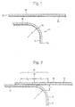
- a first sheet of metal 10 is to be joined with a second sheet of metal 20.
- the first sheet of metal 10 is arranged on top of the second sheet of metal 20.
- Both the first sheet of metal 10 and the second sheet of metal 20 include a protective layer 12, 22 made of a low-vaporizing-temperature material.
- a protective layer 12, 22 made of a low-vaporizing-temperature material.
- a material is zinc.
- Fig. 1 indicates that metal sheet 10 and metal sheet 20 are separate sheets, it should be appreciated that for the purposes of this invention, the two metal sheets may also consist of a single sheet bent or wrapped to resemble some form of a U-shape.
- the attached drawings reflect that a single protective layer 12, 22 is provided on both metal sheets 10, 20. This is by no means limiting the invention; as is usually the case in actual practice, metals sheets 10 and 20 are each provided with two opposed protective layers (not shown).
- a single protective layer 22 of metal sheet 20 is located between sheets 10 and 20 as depicted in Fig. 2, the ensuing description would obviously in no way be affected if the protective layers 12, 22 of both sheets 10 and 20 were located facing each other between the metal sheets.
- the first metal sheet 10 has a running end 18 that transitions into a curve 14 with a radius R located toward the terminal end 16.
- the second metal sheet 20 has a terminal end 26 that conforms to the shape of the running end 18 of the first metal sheet 10. This allows a tight fit between the first metal sheet 10 and the second metal sheet 20. The smaller the gap between the two metal sheets, the better formed is the resultant joint weld.
- the first metal sheet 10 is superimposed onto the second metal sheet so that the running end 18 rests flush on the terminal end 26 of the second metal sheet 20.
- the flat section running end 18 of metal sheet 10 is arranged contacting the terminal end 26 of metal sheet 20 and held to the latter by means known to one skilled in the art.
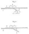
- the head on the welding machine (not shown) is arranged facing the free surface of the first metal sheet 10 in the weld area 42 along a centerline 50 (see Fig. 3).
- the weld area 42 is defined as a function of the radius of curvature of the first metal sheet 10, maximum allowable weld gap and the minimum material thickness.
- the weld area 42 is defined from a point of tangency between the two metal sheets 10 and 20.
- the weld area 42 has a first maximum distance from the point of tangency toward the radius of curvature and the gap between the two metal sheets 10 and 20 as well as a second maximum distance from the point of tangency toward the two metal sheets 10 and 20 in the direction where they are in contact.
- the distances are graphically shown as X 1 and X 2 .
- the maximum gap y is important because it affects the top profile of the weld when completed. If the gap y is too wide, then the weld will sag and create a condition where the weld may fail under even a minimal load. Avery small will reduce the weld area 42 to a width not practical to achieve repeatable weld placement with conventional methods. If the gap y is reduced to a point where the zinc vapor cannot escape during welding, the result will be in porosity and voids in the weld, contributing to a potential failure of the weld under a minimal load.
- the second maximum distance from the point of tangency X 2 maybe defined in relation to the material thickness of the sheets 10 and 20, for example, as half the minimum material thickness of the two metal sheets 10 and 20.
- the first maximum distance from the point of tangency X 1 is defined as a function of the radius R and the gap y at the first maximum distance X 1 and determined by executing the following formulas.
- the gap y between the first metal sheet 10 and the second metal sheet 20 at the first maximum distance X 1 is determined.
- the distance R-y is determined after calculating the gap y.
- the resultant first maximum distance X 1 coincides with the maximum gap y measurement along the circumference of the curved section.
- the weld area 42 has a centerline 50 from which the laser head is aligned.
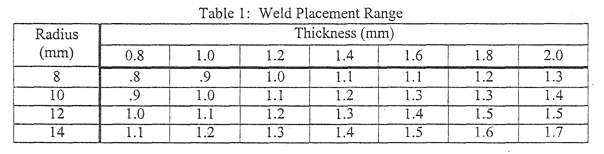
- the centerline 50 between X 1 and X 2 is can be roughly estimated once the critical values of the material thickness and the radius of curvature is known.
- the weld area 42 placement can be roughly determined through use of the following table:
- the distance of the first and second maximum distances X 1 and X 2 is the range wherein the weld can be placed.
- Other factors to be considered when applying this technique include the laser power being used to weld the materials. The variation of laser power would impact the maximum thickness of the materials to be welded together.
- Fig. 4 illustrates another embodiment of the present invention.
- the first metal sheet 100 has an angled section 110 that angles away from the second metal sheet 130, rather than a curved section as in the previous example.
- the angled section 110 has a slope that is used to determine the maximum gap allowed. The slope is used to compute the geometrical relationships of the first maximum distance X 1 and the maximum gap y allowed.
- the coating may be of another material other than zinc.
Landscapes
- Physics & Mathematics (AREA)
- Optics & Photonics (AREA)
- Engineering & Computer Science (AREA)
- Plasma & Fusion (AREA)
- Mechanical Engineering (AREA)
- Laser Beam Processing (AREA)
Abstract
Description
Claims (12)
- A method for performing a laser beam welding operation to molecularly bond two pieces of protective coated steel together including the steps of:providing at least a first metal material and a second metal material in an overlapping relationship, wherein said first metal material has a section that diverges . from said second metal material;defining a zone for performing a laser welding operation, wherein said zone extends between a first and a second edge and has a predetermined width; andperforming a laser weld within said zone.
- The method according to claim 1, further includes a gap area, wherein said gap area has a maximum gap determined by the following equation:
R is a minimum thickness of one of said first and said second metal sheets. - The method according to claim 1, wherein said protective layer is a zinc based material.
- The method according to claim 1, wherein the step of defining a zone is determined as a function of a radius of curvature of said first metal material.
- The method according to claim 1, wherein the step of defining a zone is a function of a geometric characteristic selected from following: a radius of curvature of said first metal material, a maximum gap width corresponding to one of said first and said second metal materials, and a minimum material thickness.
- The method according to claim 1, wherein said zone includes a zero gap area, wherein said zero gap area is located from a tangent point to a position on said first and said second metal materials that are in contact with each other, and a gap area, wherein said gap area is located from said tangent point toward said curved section.
- The method according to claim 6, wherein said zero gap area is defined by the following equation:
S is a minimum thickness of one of said first and said second metal sheets. - The method according to claim 6, wherein said gap area is determined from the following formula:
R is a radius of curvature of said curved section; and
A is an angle formed from said radius and X1, where A is determined from the following equation: - The method according to claim 6, wherein said first edge is located at a boundary of said zero gap area and said second edge is located at a boundary of said gap area.
- The method according to claim 9, wherein said first edge is proximate a position where said first and second metal materials are in contact.
- The method according to claim 9, wherein said second edge is proximate a position on said curved section and a position on said second metal material, wherein said first and said second metal materials are not in contact with each other.
- The method according to claim 9, wherein said gap area has a maximum gap determined by the following equation:
R is a minimum thickness of one of said first and said second metal sheets.
Applications Claiming Priority (2)
| Application Number | Priority Date | Filing Date | Title |
|---|---|---|---|
| US10/376,593 US6794603B1 (en) | 2003-03-03 | 2003-03-03 | Laser joint welding metal material |
| US376593 | 2003-03-03 |
Publications (1)
| Publication Number | Publication Date |
|---|---|
| EP1454702A1 true EP1454702A1 (en) | 2004-09-08 |
Family
ID=32824731
Family Applications (1)
| Application Number | Title | Priority Date | Filing Date |
|---|---|---|---|
| EP04100862A Withdrawn EP1454702A1 (en) | 2003-03-03 | 2004-03-03 | Method for laser welding zinc coated steel |
Country Status (9)
| Country | Link |
|---|---|
| US (1) | US6794603B1 (en) |
| EP (1) | EP1454702A1 (en) |
| JP (1) | JP2004261871A (en) |
| KR (1) | KR20040078070A (en) |
| CN (1) | CN1532021A (en) |
| AR (1) | AR043722A1 (en) |
| BR (1) | BRPI0400382A (en) |
| CA (1) | CA2459412A1 (en) |
| MX (1) | MXPA04002020A (en) |
Cited By (2)
| Publication number | Priority date | Publication date | Assignee | Title |
|---|---|---|---|---|
| GB2428615A (en) * | 2005-08-05 | 2007-02-07 | Honda Motor Co Ltd | Laser welding method and device |
| EP2716399A4 (en) * | 2011-05-24 | 2015-01-07 | Jfe Steel Corp | AUTOMOTIVE CHASSIS |
Families Citing this family (16)
| Publication number | Priority date | Publication date | Assignee | Title |
|---|---|---|---|---|
| US20040194275A1 (en) * | 2003-04-02 | 2004-10-07 | Dreistern-Werk Maschinenbau Gmbh & Co. Kg | Method and device for the production of a metal profile |
| WO2006105658A1 (en) * | 2005-04-08 | 2006-10-12 | Magna International Inc. | Laser welding of galvanized steel |
| US7910855B2 (en) * | 2005-09-23 | 2011-03-22 | Lasx Industries, Inc. | No gap laser welding of coated steel |
| CA2668133C (en) | 2008-06-13 | 2016-06-14 | Magna International Inc. | Laser welded fasteners |
| FR2938781B1 (en) * | 2008-11-27 | 2012-06-01 | Renault Sas | METHOD FOR MANUFACTURING A ZINC-PLATED HOLLOW BODY FOR A MOTOR VEHICLE |
| JP5416471B2 (en) * | 2009-04-28 | 2014-02-12 | 本田技研工業株式会社 | Method for welding vehicle frame member and vehicle frame member |
| CN201515098U (en) * | 2009-09-11 | 2010-06-23 | 上海莫仕连接器有限公司 | Electric connector |
| CN101905379B (en) * | 2010-08-05 | 2012-11-21 | 武汉钢铁(集团)公司 | High strong weather resistance cold rolling container coating plate laser welding process |
| SG10201404701SA (en) * | 2013-09-24 | 2015-04-29 | United Technologies Corp | Welded assemblies and methods of making welded assemblies |
| WO2015104781A1 (en) * | 2014-01-10 | 2015-07-16 | パナソニックIpマネジメント株式会社 | Laser welding method and laser welding device |
| JP6617443B2 (en) * | 2015-06-22 | 2019-12-11 | マツダ株式会社 | Welding method for metal parts |
| US11565343B2 (en) * | 2017-07-13 | 2023-01-31 | Kohler Co. | Laser-welded faucet |
| HUE072679T2 (en) * | 2018-03-30 | 2025-12-28 | Furukawa Electric Co Ltd | Welding method and welding apparatus |
| JP6989549B2 (en) * | 2019-03-13 | 2022-01-05 | フタバ産業株式会社 | Manufacturing method of the joint |
| WO2023110583A1 (en) * | 2021-12-17 | 2023-06-22 | Trumpf Laser- Und Systemtechnik Gmbh | Method for welding zinc-coated steel sheets using a laser beam |
| CN114735538B (en) * | 2022-04-24 | 2025-12-19 | 江苏兴达钢帘线股份有限公司 | Spool structure |
Citations (8)
| Publication number | Priority date | Publication date | Assignee | Title |
|---|---|---|---|---|
| JPS6127189A (en) * | 1984-07-17 | 1986-02-06 | Mitsubishi Electric Corp | Laser welding method |
| US4682002A (en) * | 1984-09-20 | 1987-07-21 | Prima Progetti S.P.A. | Method of laser welding sheet metal protected by low-vaporizing-temperature materials |
| EP0337182A2 (en) * | 1988-04-14 | 1989-10-18 | Bayerische Motoren Werke Aktiengesellschaft, Patentabteilung AJ-3 | Joining area of two thin sheet metals |
| DE19605341A1 (en) * | 1995-02-24 | 1996-08-29 | Volkswagen Ag | Arrangement for welding zinc@-coated sheets along overlapping edges |
| GB2339401A (en) * | 1998-07-10 | 2000-01-26 | Rover Group | Laser welding method |
| WO2001012378A1 (en) * | 1999-08-12 | 2001-02-22 | Daimlerchrysler Ag | Joining area of two coated metal sheets |
| US20010047983A1 (en) * | 2000-03-30 | 2001-12-06 | Hidetaka Degawa | Laser lap welding process of welding together overlapped plated steel sheets |
| FR2822400A1 (en) * | 2001-03-26 | 2002-09-27 | Commissariat Energie Atomique | Welding of zinc-coated steel sheet, uses wheel with larger and smaller diameter rims to separate sheets to allow lateral release of gases generated during welding |
Family Cites Families (10)
| Publication number | Priority date | Publication date | Assignee | Title |
|---|---|---|---|---|
| US4684779A (en) | 1986-01-22 | 1987-08-04 | General Motors Corporation | Laser welding metal sheets with associated trapped gases |
| US4857697A (en) * | 1987-01-21 | 1989-08-15 | Metal Box Public Limited Company | Continuous seam welding apparatus and methods |
| US4873415A (en) | 1988-02-02 | 1989-10-10 | Raycon Corporation | Method for welding galvanized material |
| DE3909471C2 (en) * | 1988-06-21 | 1993-10-07 | Fraunhofer Ges Forschung | Lap joint for welding coated workpieces using laser radiation |
| GB8824213D0 (en) * | 1988-10-15 | 1988-11-23 | Univ Essex | Welding of coated metals |
| US5142119A (en) * | 1991-03-14 | 1992-08-25 | Saturn Corporation | Laser welding of galvanized steel |
| US5183992A (en) | 1991-08-29 | 1993-02-02 | General Motors Corporation | Laser welding method |
| US5187346A (en) | 1991-08-29 | 1993-02-16 | General Motors Corporation | Laser welding method |
| US5603853A (en) * | 1995-02-28 | 1997-02-18 | The Twentyfirst Century Corporation | Method of high energy density radiation beam lap welding |
| JP2918829B2 (en) * | 1995-11-30 | 1999-07-12 | 本田技研工業株式会社 | Fuel tank manufacturing method, laser welded body, and fuel tank |
-
2003
- 2003-03-03 US US10/376,593 patent/US6794603B1/en not_active Expired - Fee Related
-
2004
- 2004-03-02 CA CA002459412A patent/CA2459412A1/en not_active Abandoned
- 2004-03-02 MX MXPA04002020A patent/MXPA04002020A/en not_active Application Discontinuation
- 2004-03-03 AR ARP040100673A patent/AR043722A1/en unknown
- 2004-03-03 BR BR0400382-9A patent/BRPI0400382A/en not_active Application Discontinuation
- 2004-03-03 JP JP2004058575A patent/JP2004261871A/en active Pending
- 2004-03-03 EP EP04100862A patent/EP1454702A1/en not_active Withdrawn
- 2004-03-03 KR KR1020040014329A patent/KR20040078070A/en not_active Withdrawn
- 2004-03-03 CN CNA2004100387186A patent/CN1532021A/en active Pending
Patent Citations (8)
| Publication number | Priority date | Publication date | Assignee | Title |
|---|---|---|---|---|
| JPS6127189A (en) * | 1984-07-17 | 1986-02-06 | Mitsubishi Electric Corp | Laser welding method |
| US4682002A (en) * | 1984-09-20 | 1987-07-21 | Prima Progetti S.P.A. | Method of laser welding sheet metal protected by low-vaporizing-temperature materials |
| EP0337182A2 (en) * | 1988-04-14 | 1989-10-18 | Bayerische Motoren Werke Aktiengesellschaft, Patentabteilung AJ-3 | Joining area of two thin sheet metals |
| DE19605341A1 (en) * | 1995-02-24 | 1996-08-29 | Volkswagen Ag | Arrangement for welding zinc@-coated sheets along overlapping edges |
| GB2339401A (en) * | 1998-07-10 | 2000-01-26 | Rover Group | Laser welding method |
| WO2001012378A1 (en) * | 1999-08-12 | 2001-02-22 | Daimlerchrysler Ag | Joining area of two coated metal sheets |
| US20010047983A1 (en) * | 2000-03-30 | 2001-12-06 | Hidetaka Degawa | Laser lap welding process of welding together overlapped plated steel sheets |
| FR2822400A1 (en) * | 2001-03-26 | 2002-09-27 | Commissariat Energie Atomique | Welding of zinc-coated steel sheet, uses wheel with larger and smaller diameter rims to separate sheets to allow lateral release of gases generated during welding |
Non-Patent Citations (1)
| Title |
|---|
| PATENT ABSTRACTS OF JAPAN vol. 0101, no. 76 (M - 491) 20 June 1986 (1986-06-20) * |
Cited By (5)
| Publication number | Priority date | Publication date | Assignee | Title |
|---|---|---|---|---|
| GB2428615A (en) * | 2005-08-05 | 2007-02-07 | Honda Motor Co Ltd | Laser welding method and device |
| US7319205B2 (en) | 2005-08-05 | 2008-01-15 | Honda Motor Co., Ltd. | Laser welding method and device |
| GB2428615B (en) * | 2005-08-05 | 2010-12-08 | Honda Motor Co Ltd | Laser welding method and device |
| EP2716399A4 (en) * | 2011-05-24 | 2015-01-07 | Jfe Steel Corp | AUTOMOTIVE CHASSIS |
| US10486752B2 (en) | 2011-05-24 | 2019-11-26 | Jfe Steel Corporation | Automobile frame component |
Also Published As
| Publication number | Publication date |
|---|---|
| JP2004261871A (en) | 2004-09-24 |
| MXPA04002020A (en) | 2005-06-20 |
| CA2459412A1 (en) | 2004-09-03 |
| BRPI0400382A (en) | 2005-01-04 |
| CN1532021A (en) | 2004-09-29 |
| US6794603B1 (en) | 2004-09-21 |
| AR043722A1 (en) | 2005-08-10 |
| US20040173586A1 (en) | 2004-09-09 |
| KR20040078070A (en) | 2004-09-08 |
Similar Documents
| Publication | Publication Date | Title |
|---|---|---|
| US6794603B1 (en) | Laser joint welding metal material | |
| US6906281B2 (en) | Method for laser welding of metal | |
| US6479168B2 (en) | Alloy based laser welding | |
| EP0178394B1 (en) | Method of laser-welding sheet metal protected by low-temperature vaporizing materials | |
| JP6108018B2 (en) | Spot welding method | |
| US20060278618A1 (en) | System and Methodology for Zero-Gap Welding | |
| RU2689293C1 (en) | Spot welding method | |
| JP6108017B2 (en) | Spot welding method | |
| US20040200813A1 (en) | Method and device for overlapping welding of two coated metal sheets with a beam of high energy density | |
| US5233149A (en) | Reprocessing weld and method | |
| EP2969347B1 (en) | Welded blank assembly | |
| JP2010264503A (en) | Steel plate lap welding method and steel plate lap weld joint | |
| JP4299705B2 (en) | Helicopter joint laser welding method for Sn or Pb plated steel sheet | |
| WO1999008829A9 (en) | Method of laser beam welding of zinc-coated steel sheet | |
| JP2014124688A (en) | Electrogas arc welding method | |
| CN100381243C (en) | Method for joining two plates made of an aluminum material and an iron or titanium material, respectively | |
| JP4216980B2 (en) | Joining structure and joining method of steel and titanium plate | |
| JP3223172B2 (en) | Welding method of laser welded body made of aluminum plated steel sheet | |
| US20060065639A1 (en) | Method of welding galvanized steel components | |
| JP2020151726A (en) | Composite welding method and welded structure of galvanized steel sheet | |
| JP3246729B2 (en) | Laser welded body | |
| CN119923302A (en) | Resistance spot welding method and method for manufacturing welded joint | |
| Pratt | Heavy-welded Structural Fabrication | |
| CN112399903A (en) | Method for thermally connecting two workpiece sections | |
| Riches et al. | Laser Welding Technology for Off-Road Vehicle Manufacture |
Legal Events
| Date | Code | Title | Description |
|---|---|---|---|
| PUAI | Public reference made under article 153(3) epc to a published international application that has entered the european phase |
Free format text: ORIGINAL CODE: 0009012 |
|
| AK | Designated contracting states |
Kind code of ref document: A1 Designated state(s): AT BE BG CH CY CZ DE DK EE ES FI FR GB GR HU IE IT LI LU MC NL PL PT RO SE SI SK TR |
|
| AX | Request for extension of the european patent |
Extension state: AL LT LV MK |
|
| 17P | Request for examination filed |
Effective date: 20050302 |
|
| AKX | Designation fees paid |
Designated state(s): AT BE BG CH CY CZ DE DK EE ES FI FR GB GR HU IE IT LI LU MC NL PL PT RO SE SI SK TR |
|
| RAP1 | Party data changed (applicant data changed or rights of an application transferred) |
Owner name: DANA AUTOMOTIVE SYSTEMS GROUP, LLC |
|
| RAP1 | Party data changed (applicant data changed or rights of an application transferred) |
Owner name: METALSA S.A. DE C.V. |
|
| STAA | Information on the status of an ep patent application or granted ep patent |
Free format text: STATUS: THE APPLICATION HAS BEEN WITHDRAWN |
|
| 18W | Application withdrawn |
Effective date: 20110110 |