EP1454683A1 - Method of forming tubular member - Google Patents
Method of forming tubular member Download PDFInfo
- Publication number
- EP1454683A1 EP1454683A1 EP02775382A EP02775382A EP1454683A1 EP 1454683 A1 EP1454683 A1 EP 1454683A1 EP 02775382 A EP02775382 A EP 02775382A EP 02775382 A EP02775382 A EP 02775382A EP 1454683 A1 EP1454683 A1 EP 1454683A1
- Authority
- EP
- European Patent Office
- Prior art keywords
- forming
- mold
- tubular material
- tubular
- preforming
- Prior art date
- Legal status (The legal status is an assumption and is not a legal conclusion. Google has not performed a legal analysis and makes no representation as to the accuracy of the status listed.)
- Granted
Links
- 238000000034 method Methods 0.000 title claims abstract description 24
- 239000000463 material Substances 0.000 claims abstract description 138
- 238000001953 recrystallisation Methods 0.000 claims abstract description 24
- 238000005452 bending Methods 0.000 claims abstract description 22
- 229910000838 Al alloy Inorganic materials 0.000 abstract description 5
- 238000010438 heat treatment Methods 0.000 description 26
- 238000003825 pressing Methods 0.000 description 15
- 239000012530 fluid Substances 0.000 description 6
- 238000007789 sealing Methods 0.000 description 5
- 238000001816 cooling Methods 0.000 description 4
- 239000011324 bead Substances 0.000 description 3
- 239000007795 chemical reaction product Substances 0.000 description 3
- 238000013003 hot bending Methods 0.000 description 3
- 238000010276 construction Methods 0.000 description 2
- 230000003247 decreasing effect Effects 0.000 description 2
- 239000007769 metal material Substances 0.000 description 2
- 239000000047 product Substances 0.000 description 2
- 230000015572 biosynthetic process Effects 0.000 description 1
- 230000006866 deterioration Effects 0.000 description 1
- 238000010586 diagram Methods 0.000 description 1
- 230000000694 effects Effects 0.000 description 1
- 238000005485 electric heating Methods 0.000 description 1
- 230000002401 inhibitory effect Effects 0.000 description 1
- 238000004519 manufacturing process Methods 0.000 description 1
- 239000002184 metal Substances 0.000 description 1
- 229910052751 metal Inorganic materials 0.000 description 1
- 150000002739 metals Chemical class 0.000 description 1
- 238000012986 modification Methods 0.000 description 1
- 230000004048 modification Effects 0.000 description 1
- 238000013021 overheating Methods 0.000 description 1
- 230000002093 peripheral effect Effects 0.000 description 1
- 230000008961 swelling Effects 0.000 description 1
- 230000001360 synchronised effect Effects 0.000 description 1
Images



Classifications
-
- B—PERFORMING OPERATIONS; TRANSPORTING
- B21—MECHANICAL METAL-WORKING WITHOUT ESSENTIALLY REMOVING MATERIAL; PUNCHING METAL
- B21D—WORKING OR PROCESSING OF SHEET METAL OR METAL TUBES, RODS OR PROFILES WITHOUT ESSENTIALLY REMOVING MATERIAL; PUNCHING METAL
- B21D26/00—Shaping without cutting otherwise than using rigid devices or tools or yieldable or resilient pads, i.e. applying fluid pressure or magnetic forces
- B21D26/02—Shaping without cutting otherwise than using rigid devices or tools or yieldable or resilient pads, i.e. applying fluid pressure or magnetic forces by applying fluid pressure
- B21D26/033—Deforming tubular bodies
-
- C—CHEMISTRY; METALLURGY
- C22—METALLURGY; FERROUS OR NON-FERROUS ALLOYS; TREATMENT OF ALLOYS OR NON-FERROUS METALS
- C22F—CHANGING THE PHYSICAL STRUCTURE OF NON-FERROUS METALS AND NON-FERROUS ALLOYS
- C22F1/00—Changing the physical structure of non-ferrous metals or alloys by heat treatment or by hot or cold working
- C22F1/04—Changing the physical structure of non-ferrous metals or alloys by heat treatment or by hot or cold working of aluminium or alloys based thereon
-
- Y—GENERAL TAGGING OF NEW TECHNOLOGICAL DEVELOPMENTS; GENERAL TAGGING OF CROSS-SECTIONAL TECHNOLOGIES SPANNING OVER SEVERAL SECTIONS OF THE IPC; TECHNICAL SUBJECTS COVERED BY FORMER USPC CROSS-REFERENCE ART COLLECTIONS [XRACs] AND DIGESTS
- Y10—TECHNICAL SUBJECTS COVERED BY FORMER USPC
- Y10T—TECHNICAL SUBJECTS COVERED BY FORMER US CLASSIFICATION
- Y10T29/00—Metal working
- Y10T29/49—Method of mechanical manufacture
- Y10T29/49805—Shaping by direct application of fluent pressure
Definitions
- the present invention relates to a process for forming a tubular member which enables a tubular member of high precision to be formed from a tubular metal material by hot forming the material using a preforming mold, which is kept at temperatures equal to or higher than the recrystallization temperature of the material, in combination with a final forming mold, which is kept at temperatures equal to or lower than the recrystallization temperature of the same.
- bulge process has been known as one of the technical means of press forming for forming a tubular metal material into a tubular member of a deformed cross section having expanded portions in the appropriate places across its length.
- the bulge process is a process for forming a tubular material into a desired form by mold clamping a mold in which the tubular material is set and then applying an internal pressure by fluid pressure to the interior of the tubular material to allow the material to expand and fit on the surface of the mold cavity.
- Such a conventional bulge process is usually carried out by cold forming at, for example, room temperature.
- the cold bulging however, has a problem of its processability being poor because it requires a very high pressure to be applied to the interior of the tubular material to be processed, and therefore, needing large-scale equipment, as a result, making it hard to process materials of high strength.
- the object of the invention is to provide a novel process for forming a tubular member which enables a tubular member, as an end product, of high quality and high precision to be formed from a tubular member by hot preforming the tubular material using a preforming mold, kept at temperatures equal to or higher than the recrystallization temperature of the material, and hot final forming the preformed material using a final forming mold, kept at temperatures equal to or lower than the recrystallization temperature of the material and which drastically increases the productivity.
- a process for forming a tubular member which forms a tubular material into a desired shape while applying an internal pressure to the material including: a preforming step of preforming a preformed tube from the tubular material by setting the material into the cavity of a preforming mold and mold clamping the preforming mold while applying an internal pressure to the material; and a final forming step of final forming the preformed tube into a tubular member having a cross section of desired shape by setting the preformed tube into the cavity of a final forming mold and mold clamping the final forming mold while applying a predetermined internal pressure to the preformed tube, wherein the temperature of the preforming mold, in which preforming is carried out, is controlled so that the mold is kept at temperatures equal to or higher than the recrystallization temperature of the tubular material, while the temperature of the final forming mold, in which final forming is carried out, is controlled so that the mold is kept at temperatures equal
- a tubular member of high precision and high quality can be formed and the productivity is drastically increased because forming of a tubular material is divided into two steps: a hot preforming step using a preforming mold kept at temperatures equal to or higher than the recrystallization temperature of the material; and a hot final forming step using a final forming mold kept at temperatures equal to or lower than the recrystallization temperature of the material.
- a tubular member having expanded portions can be formed with high precision and high quality and the productivity is drastically increased.
- a tubular member having expanded portions and bent portions can be formed with high precision and high quality and the productivity is drastically increased.
- FIGS. 1A and 1B are perspective views of a tubular material after tube-expanding (bulge) forming and a tubular member after completion of forming, respectively;
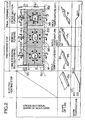
- FIG. 2 is a diagram showing production steps of producing a tubular member by hot forming according to the present invention
- FIG. 3 is a view in cross section along the line 3-3 of FIG. 2
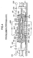
- FIG. 4 is a view in cross section along the line 4-4 of FIG. 2
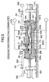
- FIG. 5 is a view in cross section along the line 5-5 of FIG. 2
- FIG. 6 is an enlarged view in cross section along the line 6-6 of FIG. 5
- FIG. 7 is a view showing the state in which a tubular material undergoes axial heat shrinkage at a final forming step.
- a tubular material Pa formed in accordance with the forming process of this embodiment is a hollow cylindrical material of aluminium alloy with both its ends open, and it is heated to about 500°C by heating means before being carried in a first mold M1 for preforming.
- heating means electric heating is employed in this embodiment, but heating may also be carried out in a furnace.
- the first, second and third molds M1, M2 and M3 are arranged in parallel on a base 1 and the first and second molds M1 and M2 are used in the preforming step of preforming the tubular material and the third mold M3 in the final forming step of forming the preformed tube.
- the first, second and third molds M1, M2 and M3 are formed of stationary molds 2, 202, 302 mounted fixedly in line on a base 1 and moving molds 3, 203, 303, which correspond to the respective stationary molds; the moving molds 3, 203, 303 are integrally connected to an up-and-down member UD which extends over the moving molds; to the up-and-down member UD an up-and-down cylinder 4 as a mold clamping cylinder is connected; and the first, second and third moving molds 3, 203, 303 are synchronized and allowed to perform up-and-down action by the expansion action of the up-and-down cylinder 4. Between the base 1 and the up-and-down member UD a guide GU is provided and the guide GU guides the up-and-down movement of the up-and-down member UD.
- the first mold M1 is a tube-expanding forming mold for carrying out hot tube-expanding forming (hot bulge-forming) at temperatures equal to or higher than the recrystallization temperature of a hollow cylindrical tubular material of aluminium alloy (hereinafter referred to as a tubular material Pa), which is heated to and kept at about 500°C in advance, and in the tube-expanding forming mold, conventionally known heating means such as high-frequency-current heating means, heater heating means or the like is used as heating means HE1 for heating the mold to about 500°C.
- heating means HE1 for heating the mold to about 500°C.
- the second mold M2 is a bending forming mold for carrying out hot bending forming at temperatures equal to or higher than the recrystallization temperature of the expanded tubular material formed in the first mold M1 (hereinafter referred to as a tubular material Pb), and also in the bending forming mold M2, heating means HE2 for heating the mold M2 to about 500°C, for example, high-frequency-current heating means is provided, just like in the case of the first mold M1. High-frequency-current heating means, heater heating means and the other conventionally known heating means are used as heating means HE1.
- the preforming step according to the present invention is formed of the hot tube-expanding forming (hot bulge-forming) step and the hot bending forming step in combination.
- the third mold M3 is a final forming mold for carrying out cross-section forming by crushing the tubular material(hereinafter referred to as tubular material Pc) having undergone hot tube-expanding forming (bulging) and hot bending forming in the first and second molds M1, M2, respectively, into a desired shape at temperatures equal to or lower than the recrystallization temperature of the tubular material Pc, and in the final forming mold M3, heating means HE3 for heating the mold M3 to about 200°C, for example, fluid heating means is provided.
- tubular material Pc tubular material having undergone hot tube-expanding forming (bulging) and hot bending forming in the first and second molds M1, M2, respectively, into a desired shape at temperatures equal to or lower than the recrystallization temperature of the tubular material Pc
- heating means HE3 for heating the mold M3 to about 200°C, for example, fluid heating means is provided.
- tubular material Pc Since the tubular material Pc is still in the heated state (preformed at about 500°C), when it is set in the third mold M3, heat is transferred from the tubular material Pc to the third mold M3, which is kept at temperatures equal to or lower than the recrystallization temperature of the tubular material Pc, and thus the tubular material Pc undergoes hot final forming in the third mold M3 while being controlled so that its temperature is rather decreased.
- tubular material Pa The tubular material of aluminium alloy (hereinafter referred to as tubular material Pa) heated to about 500°C in advance is carried to the first mold M1 and introduced into the first mold M1 which has also been heated to about 500°C, that is, the temperature equal to or higher than the recrystallization temperature of the tubular material Pa, and part of the tubular material Pa in a state of being kept at the temperature equal to or higher than the recrystallization temperature, in this embodiment the sites B1, B2 near its opposite ends (see FIG. 1A), undergo hot tube-expanding forming (hot bulgeforming).
- tubular material Pa The tubular material of aluminium alloy heated to about 500°C in advance is carried to the first mold M1 and introduced into the first mold M1 which has also been heated to about 500°C, that is, the temperature equal to or higher than the recrystallization temperature of the tubular material Pa, and part of the tubular material Pa in a state of being kept at the temperature equal to or higher than the recrystallization temperature, in this embodiment
- the first mold M1 includes a stationary mold on the base 1, that is, a lower mold 2 and a moving mold, that is, an upper mold 3 whose up-and-down action above the lower mold 2 is controlled by the action of the up-and-down cylinder 4; on the top surface of the lower mold 2 is formed a lower mold forming surface 2m for forming the lower half of the tubular material Pa; on the bottom surface of the upper mold 3 is formed an upper mold forming surface 3m for forming the upper half of the tubular material Pa; and when mold clamping the first mold M1, the forming surfaces 2m and 3m form a cavity 5.
- hold means H1 for fixing opposite ends of the tubular material Pa.
- the hold means H1 are each provided with left and right holders 6, 7 on each side of the first mold M1, and the holders 6, 7 are movable back and forth relative to the first mold M1 and their movement on guides 8, 9, which are provided on the base 1, is controlled by the operation of actuators 10, 11.
- the opposite end portions of the tubular material Pa are fitted and fixed into the supporting holes 6a, 7a of the left and right holders 6, 7 by the forward movement thereof.
- the pressing means P1 include left and right pressing cylinders 12, 13, respectively; pressing members 16, 17 fixed on the tip of the rod portions 12r, 13r of the pressing cylinder 12, 13 are fitted into the support hole 6a, 7a of the left and right holders 6, 7 in the back and forth movable manner; the tips of the pressing members 16, 17 are respectively engaged with the opposite ends of the tubular material Pa by the extension action of the left and right pressing cylinders 12, 13; and the tubular material Pa can be axially pressed from its opposite sides by the subsequent forward movement of the pressing members 16, 17.
- O rings 19, 20 are provided between the left and right pressing members 16, 17 and the supporting holes 6a, 7a and between the supporting holes 6a, 7a and outer peripheral surfaces of opposite end portions of the tubular material Pa.
- these O rings 19, 20 can provide a fluid tight seal between the tubular material Pa and the holders 6, 7 and between the tubular material Pa and the pressing members 16, 17, when the pressing members 16, 17 are engaged with the tubular material Pa.
- compressed air supplying means A1 for pressurizing the inside of the tubular material Pa.
- the compressed air supplying means A1 are so constructed that they feed compressed air under pressure from compressed air supplying sources 22 to the closed hollow portion of the tubular material Pa via compressed air circuits 23 and air introducing paths 24 pierced in the pressing members 16, 17.
- the first mold M1 After introducing and setting the tubular material Pa, which has been heated to about 500°C in the heating step as a pre-step, in the first mold M1, which has also been heated to about 500°C by the heating means HE1, the first mold M1 is mold clamped by the operation of the mold clamping cylinder 4.
- the rod portions 12r, 13r press the tubular material Pa axially and allow pressurizing air to be fed from the compressed air source 22 into the tubular material Pa via the compressed air supplying path 23 and the air introducing path 24 while carrying out the axial pushing, and an internal pressure is applied to the tubular material Pa.
- the sites B1, B2 of opposite end portions of the tubular material Pa undergo tube-expanding forming (bulge-forming) so that the tubular material Pa follows the upper and lower forming surfaces 3m, 2m of the cavity 5.
- the tube-expanding (bulge) forming is hot forming (about 500°C)
- the pressure required for the forming is low compared with the case of cold forming, as a result, the forming time is reduced.
- tubular material Pb The tubular material after tube-expanding forming (hereinafter referred to as tubular material Pb) is drawn out from the first mold M1 by opening the same after allowing the left and right holder 6,7 to move backward.
- tubular material Pb the sites B1, B2 near its opposite ends undergo tube-expanding forming (bulge forming), as shown in FIG.1A and 2.
- the second step is a bending forming step of bending forming the tubular material Pb, which has undergone tube-expanding forming in the previous step.
- the tubular material Pb having undergone tube-expanding forming (bulge-forming) in the above-mentioned first step is carried to the second mold M2 by known carrying means with still in the heated state, not shown in the figure, and set in the same to undergo hot (500°C) bending forming, which is carried out while applying an internal pressure to the tubular material.
- the second mold M2 has almost the same construction as the first mold M1, except that a pressing means P1 is omitted, as shown in FIG. 4.
- the second mold M2 includes a stationary mold on the base 1, that is, a lower mold 202 and a moving mold, that is, an upper mold 203 whose up-and-down action above the lower mold 202 is controlled; on the top surface of the lower mold 202 is formed a lower mold forming surface 202m for bending forming the lower half of the tubular material Pb; on the bottom surface of the upper mold 203 is formed an upper mold forming surface 203m for bending forming the upper half of the tubular material Pb; and when mold clamping the second mold M2, the forming surfaces 202m and 203m form a cavity 205.
- hold means H2 for fixing opposite ends of the tubular material Pb, just like in the case of the first mold M1.
- the hold means H2 are each provided with left and right holders 206, 207, and the back and forth movement of the holders 206, 207 relative to the second mold 2 is controlled by actuators 210, 211 which are formed of expansion cylinders.
- actuators 210, 211 which are formed of expansion cylinders.
- sealing means S2 which are formed of O rings 219 to air-tightly seal opposite open ends of the tubular material Pb.
- compressed air supplying means A2 for pressurizing the inside of the tubular material Pb.
- the compressed air supplying means A2 are so constructed that they feed compressed air under pressure from compressed air supplying sources 222 to the closed hollow portion of the tubular material Pb, which has undergone bulging, via compressed air circuits 223 and air introducing paths 224 pierced in the holders 206, 207.
- the tubular material Pb having undergone tube-expanding forming (bulge-forming) in the previous step, which is still in the heated state, is introduced into the second mold M2 in the opened state, which has been heated to about 500°C by the heating means HE2, and set in the same.
- opposite end portions of the tubular material Pb are held in the second mold M2 by allowing the left and right holders 206, 207 to take a forward action by the operation of the actuators 210, 211, and at the same time, the open ends are air-tightly sealed by the sealing means S2.
- an internal pressure is applied to the tubular material Pb by feeding pressurizing air under pressure from the compressed air sources 222 into the tubular material Pb via the compressed air supplying paths 223 and the air introducing paths 224 and the second mold M2 is mold clamped by allowing the upper mold 203 to descend by the operation of the mold clamping cylinder 4 to allow the tubular material Pb, which has undergone tube-expanding (bulge) forming, to fit to the bending forming surfaces 203m, 202m of the upper and lower molds 203, 202, and hot (about 500°C) bending is carried out in such a state.
- tubular material Pc a preformed tube
- tubular material Pc has its middle portion bended, as shown in FIG. 1B, and its cross section takes the form of an oval crushed upwards and downwards.
- the preforming step following the present invention is thus made up of the tube-expanding forming (bulge forming) step and the bending forming step.
- This preforming step enables the speeding up of the forming, reduction of the forming pressure, downsizing of the forming equipment and simplification of the forming equipment structure compared with the cold forming, since it is hot forming carried out at temperatures equal to or higher than the recrystallization temperature (about 500°C) of the tubular material.
- This step is a cross-section forming step (final forming step) in which the cross section of the tubular material Pc, which has undergone bending forming, is formed into a final completed shape.
- the tubular material Pc which has undergone tube-expanding forming (bulge forming) and bending forming in the first and second steps and is still in the heated state, is introduced into the third mold M3 by known carrying means, not shown in the figure, and set in the same to undergo cross-section forming.
- the third mold M3 has substantially the same construction as the second mold M2. As shown in FIGS. 5, 6, it includes a stationary lower mold 302 and an upper mold 303 whose up-and-down action above the lower mold 302 is controlled, and on the top surface of the lower mold 302 and on the bottom surface of the upper mold 303 are formed forming surfaces 302m, 303m for forming the cross section of the tubular material Pc, respectively. When the third mold M3 is mold clamped, the forming surfaces 302m and 303m form a cavity 305 for cross-section forming.
- constraining beads 302b, 303b are formed on opposite sides of the forming surfaces 303m, 302m, as shown in FIG. 6, and these constraining beads 302b, 303b are engaged with opposite ends of the tubular material Pc in the final forming step to constrain the axial shrinkage of the tubular material Pc during the final forming.
- hold means H3 for fixing opposite ends of the tubular material Pc, which has undergone bending forming.
- the hold means H3 are each provided with left and right holder 306, 307, and the back and forth movement of the holders 306, 307 relative to the third mold M3 is controlled by actuators 310, 311 which are made up of expansion cylinders.
- actuators 310, 311 which are made up of expansion cylinders.
- sealing means S3 which are made up of O rings 319 to air-tightly seal opposite open ends of the tubular material Pc.
- compressed air supplying means A3 for pressurizing the inside of the tubular material Pc.
- the compressed air supplying means A3 are so constructed that they feed compressed air under pressure from compressed air supplying sources 322 to the closed hollow portion of the tubular material Pc, which has undergone bending forming, via compressed air circuits 323 and air introducing paths 324 pierced in the holders 306, 307.
- the third mold M3 is kept at about 200°C by heating means HE3. Since the tubular material (preformed tube) Pc, which has undergone bending forming at the second step, is still in the heated state (formed at about 500°C), when it is set in the third mold M3, heat is transferred from the tubular material Pc to the third mold M3. As a result, the temperature of the mold is increased, but on the other hand, the tubular material Pc is controlled so that its temperature is decreased. Thus, the tubular material Pc, which is formed into an end product shape using the third mold, is not affected by the heat of the third mold M3 and prevented from deforming by heat in the third mold M3.
- the tubular material Pc which has undergone bending forming (preforming) in the second mold M2, is rotated around the axis L-L at about 90° (the angle varies depending on the tubular material Pd) by rotating means not shown in the figure, as shown in FIG. 2, and then carried in the third mold M3 in the open state and set in the same.
- opposite end portions of the tubular material Pc are fixed in the third mold M3 by the forward movement of the holders 306, 307, and at the same time, they are provided with a fluid tight seal by sealing means S3, and the holder 306, 307 are moved forward.
- the upper mold 303 is allowed to descend by the operation of the mold clamping cylinder 4 to mold clamp the third mold M3, an internal pressure is applied to the inside of the tubular material Pc by compressed air supplying means A3, and load is applied to the tubular material Pc in such a state from the direction orthogonal to the length of the tubular material Pc to crush the cross section of the tubular material so that the material to fit to the forming surfaces of the upper and lower molds 303, 302.
- the tubular material Pc undergoes cross-section forming and is formed into a final completed shape having, for example, rectangular cross section with small R corner portions.
- the third mold M3 is kept at about 200°C, that is, at the temperature equal to or lower than the recrystallization temperature of the tubular material (preformed tube) Pc, while the tubular material Pc is kept at the temperature (about 500°C) higher than that of the third mold M3 (about 200°C), and therefore, hot forming of the tubular material Pc is substantially possible even in the third mold M3, which is kept at temperatures equal to or lower than the recrystallization temperature of the tubular material Pc. Accordingly, the tubular material Pc is not affected and deformed by heat from the third mold M3.
- the final cross-section forming is carried out while keeping the temperature of the third mold M3 equal to or lower than the recrystallization temperature of the tubular material Pc, and then the tubular material Pc is cooled while keeping the mold M3 in the mold clamped state for a specified period of time.
- This operation inhibits variation in shrinkage of the tubular material Pc which is created by cooling when the material is drawn out of the third mold M3 after the final forming.
- the operation also prevents the tubular material Pc from deforming which is caused when the material is handled, in other words, when the tubular member P shown in FIG. 1B is drawn out of the third mold M3 while opening the same. Furthermore, the tubular member P is not deformed by the external conditions such as air cooling after it is drawn out from the mold.
- the combination of the first to third steps specifically, the combination of the hot preforming using the first and second molds M2, M3 at temperatures equal to or higher than the recrystallization of the tubular material and the hot final forming using the third mold M3 at temperatures equal to or lower than the recrystallization of the tubular material enables formation of a tubular member P which is free from variation in precision, of high precision and of high quality, and besides, drastic increase in the productivity.
- tubular member P as an end product, formed in the first to third steps is used as a frame member, etc for vehicles.
- the forming process of this invention is applied to the case where a tubular material is aluminium alloy, but it is without saying that the process can also be applied to tubular materials of other metals.
- the temperatures of heating tubular materials and molds are controlled depending on the material used.
- air is used as compressed fluid for applying an internal pressure to the tubular material, other fluids can also be used as long as they produce the same effect.
Landscapes
- Chemical & Material Sciences (AREA)
- Physics & Mathematics (AREA)
- Engineering & Computer Science (AREA)
- Mechanical Engineering (AREA)
- Fluid Mechanics (AREA)
- Thermal Sciences (AREA)
- Crystallography & Structural Chemistry (AREA)
- Materials Engineering (AREA)
- Metallurgy (AREA)
- Organic Chemistry (AREA)
- Shaping Metal By Deep-Drawing, Or The Like (AREA)
- Bending Of Plates, Rods, And Pipes (AREA)
Abstract
Description
Claims (3)
- A process for forming a tubular member which forms a tubular material into a desired shape while applying an internal pressure to the material, comprising:a preforming step of preforming tubular materials (Pa, Pb) into a preformed tube (Pc) by setting the materials (Pa, Pb) into the cavities (5, 205) of preforming molds (M1, M2) and mold clamping the preforming molds (M1, M2) while applying an internal pressure to the materials (Pa, Pb); anda final forming step of final forming the preformed tube (Pc) into a tubular member (P) having a cross section of desired shape by setting the preformed tube (Pc) into the cavity (305) of a final forming mold (M3) and mold clamping the final forming mold (M3) while applying a predetermined internal pressure to the preformed tube (Pc), whereinthe temperature of the molds is controlled so that the preforming molds (M1, M2) for carrying out preforming are kept at temperatures equal to or higher than the recrystallization temperature of the tubular materials (Pa, Pb), while the final forming mold (M3) for carrying out final forming is kept at temperatures equal to or lower than the recrystallization temperature of the preformed tube (Pc).
- The process for forming a tubular member according to claim 1, wherein the preforming is tube-expanding forming.
- The process for forming a tubular member according to claim 1, wherein the preforming is tube-expanding forming and bending forming.
Applications Claiming Priority (3)
| Application Number | Priority Date | Filing Date | Title |
|---|---|---|---|
| JP2001325882A JP2003126923A (en) | 2001-10-24 | 2001-10-24 | Method of forming tubular member |
| JP2001325882 | 2001-10-24 | ||
| PCT/JP2002/011009 WO2003035299A1 (en) | 2001-10-24 | 2002-10-23 | Method of forming tubular member |
Publications (3)
| Publication Number | Publication Date |
|---|---|
| EP1454683A1 true EP1454683A1 (en) | 2004-09-08 |
| EP1454683A4 EP1454683A4 (en) | 2007-03-28 |
| EP1454683B1 EP1454683B1 (en) | 2008-05-21 |
Family
ID=19142359
Family Applications (1)
| Application Number | Title | Priority Date | Filing Date |
|---|---|---|---|
| EP02775382A Expired - Lifetime EP1454683B1 (en) | 2001-10-24 | 2002-10-23 | Method of forming tubular member |
Country Status (6)
| Country | Link |
|---|---|
| US (1) | US7464572B2 (en) |
| EP (1) | EP1454683B1 (en) |
| JP (1) | JP2003126923A (en) |
| CN (1) | CN1275714C (en) |
| CA (1) | CA2463894C (en) |
| WO (1) | WO2003035299A1 (en) |
Cited By (5)
| Publication number | Priority date | Publication date | Assignee | Title |
|---|---|---|---|---|
| WO2006086935A1 (en) * | 2005-02-19 | 2006-08-24 | Tower Automotive Hydroforming Gmbh & Co. Kg | Method and device for producing components |
| FR2882281A1 (en) * | 2005-02-24 | 2006-08-25 | Ems Sa | Hydroforming machine for moulding articles by high-pressure water injection inside mould has hydroforming post linked to two loading and preforming stations |
| ITMI20101820A1 (en) * | 2010-10-05 | 2012-04-06 | Beretta Armi Spa | PROCEDURE FOR THE REALIZATION OF LOADERS OF FIREARMS, IN PARTICULAR GUNS AND / OR SIMILAR, AND LOADER OBTAINED THROUGH THIS PROCEDURE |
| EP2143508A4 (en) * | 2007-04-18 | 2013-07-17 | Nippon Steel & Sumitomo Metal Corp | HYDROFORMING PROCESS |
| WO2018010978A1 (en) * | 2016-07-11 | 2018-01-18 | Sapa As | Hot metal gas formed roof rail and method of manufacture thereof |
Families Citing this family (35)
| Publication number | Priority date | Publication date | Assignee | Title |
|---|---|---|---|---|
| DE102004013872B4 (en) * | 2004-03-20 | 2006-10-26 | Amborn, Peter, Dr.-Ing. | Method and tool for forming a metallic hollow body in a forming tool under elevated temperature and under internal pressure |
| JP4726524B2 (en) * | 2004-03-31 | 2011-07-20 | 古河スカイ株式会社 | Aluminum alloy tube and aluminum alloy automobile structural member using the same |
| CN1314496C (en) * | 2005-01-19 | 2007-05-09 | 哈尔滨工业大学 | A preforming device for internal high pressure forming of hollow structural parts |
| WO2007018499A1 (en) * | 2005-07-26 | 2007-02-15 | Aquaform, Inc. | Apparatus and method for forming shaped parts |
| JP4630759B2 (en) * | 2005-08-18 | 2011-02-09 | 本田技研工業株式会社 | Bulge forming method |
| DE102005049050B4 (en) * | 2005-10-13 | 2010-12-23 | Saf-Holland Gmbh | Method for producing an axle component |
| CN100464890C (en) * | 2005-12-19 | 2009-03-04 | 河南科技大学 | A method and device for forming a magnesium alloy pipe fitting |
| US8343408B2 (en) * | 2006-10-12 | 2013-01-01 | Smith Michael P | Method of molding an endotracheal tube for tracheal intubation |
| US7661283B2 (en) * | 2006-12-22 | 2010-02-16 | Honda Motor Co., Ltd. | Bulging method and apparatus |
| ITMI20072372A1 (en) * | 2007-12-19 | 2009-06-20 | Ibf S P A | PROCEDURE FOR BENDING TUBULAR ARTICLES WITH A REPORT> 3 BETWEEN THE BENDING RADIUS AND THE EXWERN DIAMETER OF THE FINISHED TUBE |
| CN101219451B (en) * | 2008-01-25 | 2010-06-02 | 哈尔滨工业大学 | Forming method of long tube part with local convex shape |
| US7661282B2 (en) * | 2008-03-21 | 2010-02-16 | Gm Global Technology Operations, Inc. | Hot forming process for metal alloy sheets |
| JP2010000526A (en) * | 2008-06-20 | 2010-01-07 | Kyoei Seisakusho:Kk | Method of manufacturing twin tank rail for two-wheeled vehicle |
| KR101069023B1 (en) * | 2008-06-30 | 2011-09-29 | 현대하이스코 주식회사 | Hydroforming Method for Strengthening Front Axle |
| SE533223C2 (en) * | 2008-10-08 | 2010-07-27 | Sapa Heat Transfer Ab | Method for forming header tank made of aluminum |
| JP5380189B2 (en) | 2009-07-21 | 2014-01-08 | 本田技研工業株式会社 | Hot bulge forming equipment |
| JP5692974B2 (en) * | 2009-07-30 | 2015-04-01 | 株式会社ワイテック | Method and apparatus for forming cylindrical body |
| JP5437730B2 (en) * | 2009-07-31 | 2014-03-12 | 本田技研工業株式会社 | Hot bulge forming apparatus, hot bulge forming method, and hot bulge formed product |
| CN102407255B (en) * | 2010-09-21 | 2015-02-11 | 吉林省车桥汽车零部件有限公司 | Production method of transition bridge bent tube of heavy-duty truck |
| ES2387857B1 (en) * | 2010-11-30 | 2013-11-07 | Gamesa Innovation & Technology S.L. | DEVICE FOR REGULATION OF THE DEFINITIONS OF THE MILK OF AN AERODYNAMIC GEOMETRY MOLD AND MOLDING METHOD WITH SUCH DEVICE |
| US8356506B2 (en) | 2011-02-25 | 2013-01-22 | Szuba Consulting, Inc. | Method of forming industrial housings |
| US8806733B2 (en) | 2011-08-16 | 2014-08-19 | Szuba Consulting, Inc. | Method of forming a universal joint |
| TWI504451B (en) * | 2012-09-14 | 2015-10-21 | Ind Tech Res Inst | Method and device for producing a tube by hydroforming |
| JP6137512B2 (en) | 2012-11-08 | 2017-05-31 | デーナ、オータモウティヴ、システィムズ、グループ、エルエルシー | Method for forming a drive shaft tube |
| CN103464562B (en) * | 2013-09-14 | 2016-03-30 | 中国第一汽车股份有限公司 | Cavity low-internal-pressure manufacturing process |
| US20150315666A1 (en) | 2014-04-30 | 2015-11-05 | Ford Global Technologies, Llc | Induction annealing as a method for expanded hydroformed tube formability |
| US9545657B2 (en) * | 2014-06-10 | 2017-01-17 | Ford Global Technologies, Llc | Method of hydroforming an extruded aluminum tube with a flat nose corner radius |
| JP6381967B2 (en) * | 2014-05-22 | 2018-08-29 | 住友重機械工業株式会社 | Molding apparatus and molding method |
| JP6400952B2 (en) * | 2014-06-18 | 2018-10-03 | 住友重機械工業株式会社 | Molding system and molding method |
| JP6745090B2 (en) * | 2015-03-31 | 2020-08-26 | 住友重機械工業株式会社 | Molding equipment |
| CN105583252A (en) * | 2016-03-07 | 2016-05-18 | 北京航空航天大学 | Hydroforming method of axis continuous bending special-shaped pipe fitting |
| JP7240411B2 (en) * | 2018-10-01 | 2023-03-15 | 住友重機械工業株式会社 | Expansion molding device |
| CN109604412A (en) * | 2018-11-08 | 2019-04-12 | 北京航星机器制造有限公司 | A kind of superplastic forming method of buried intake port for aluminum alloy projectile |
| JP6704982B2 (en) * | 2018-12-28 | 2020-06-03 | 住友重機械工業株式会社 | Molding equipment |
| CN115648515B (en) * | 2022-10-19 | 2025-09-26 | 如皋市万通防腐有限公司 | A polytetrafluoroethylene pipe isostatic forming device and forming process thereof |
Family Cites Families (17)
| Publication number | Priority date | Publication date | Assignee | Title |
|---|---|---|---|---|
| JPS62259623A (en) | 1986-05-02 | 1987-11-12 | Yamaha Motor Co Ltd | Hot bulging method |
| JPS62259624A (en) | 1986-05-02 | 1987-11-12 | Yamaha Motor Co Ltd | Hot bulging device |
| JPS62270229A (en) | 1986-05-16 | 1987-11-24 | Yamaha Motor Co Ltd | Hot bulging device |
| US5481892A (en) * | 1989-08-24 | 1996-01-09 | Roper; Ralph E. | Apparatus and method for forming a tubular member |
| US5890387A (en) * | 1989-08-24 | 1999-04-06 | Aquaform Inc. | Apparatus and method for forming and hydropiercing a tubular frame member |
| DE4103082A1 (en) * | 1991-02-01 | 1992-08-27 | Eichelberg & Co Gmbh H D | METHOD FOR THE HYDROSTATIC FORMING OF HOLLOW BODIES FROM COLD FORMABLE METAL AND DEVICE FOR IMPLEMENTING THE METHOD |
| JP2678963B2 (en) * | 1992-10-30 | 1997-11-19 | 川崎重工業株式会社 | Method of manufacturing flat tubes |
| DE4427201C2 (en) * | 1993-11-26 | 1996-09-12 | Ges Innenhochdruckverfahren | Process for the production of hollow camshafts |
| US5992197A (en) * | 1997-03-28 | 1999-11-30 | The Budd Company | Forming technique using discrete heating zones |
| GB9727063D0 (en) | 1997-12-23 | 1998-02-18 | Gkn Sankey Ltd | A hydroforming process |
| JPH11309521A (en) | 1998-04-24 | 1999-11-09 | Nippon Steel Corp | Bulge forming method for stainless steel tubular members |
| US6134931A (en) * | 1999-05-26 | 2000-10-24 | Husky Injection Molding Systems Ltd. | Process and apparatus for forming a shaped article |
| DE19928873B4 (en) * | 1999-06-24 | 2004-08-12 | Benteler Ag | Method and device for the internal pressure molding of a hollow metallic workpiece made of aluminum or an aluminum alloy |
| US6322645B1 (en) * | 1999-09-24 | 2001-11-27 | William C. Dykstra | Method of forming a tubular blank into a structural component and die therefor |
| JP2002018533A (en) * | 2000-07-04 | 2002-01-22 | Mazda Motor Corp | Method for manufacturing metal molded body using fluid and metal molded body |
| JP2002126826A (en) * | 2000-10-24 | 2002-05-08 | Kawasaki Heavy Ind Ltd | High temperature bulge forming method and high temperature bulge forming apparatus |
| JP3482522B2 (en) | 2000-10-24 | 2003-12-22 | 川崎重工業株式会社 | High temperature bulge forming equipment |
-
2001
- 2001-10-24 JP JP2001325882A patent/JP2003126923A/en active Pending
-
2002
- 2002-10-23 WO PCT/JP2002/011009 patent/WO2003035299A1/en not_active Ceased
- 2002-10-23 CA CA002463894A patent/CA2463894C/en not_active Expired - Fee Related
- 2002-10-23 EP EP02775382A patent/EP1454683B1/en not_active Expired - Lifetime
- 2002-10-23 CN CNB02821160XA patent/CN1275714C/en not_active Expired - Fee Related
- 2002-10-23 US US10/492,510 patent/US7464572B2/en not_active Expired - Fee Related
Non-Patent Citations (2)
| Title |
|---|
| No further relevant documents disclosed * |
| See also references of WO03035299A1 * |
Cited By (7)
| Publication number | Priority date | Publication date | Assignee | Title |
|---|---|---|---|---|
| WO2006086935A1 (en) * | 2005-02-19 | 2006-08-24 | Tower Automotive Hydroforming Gmbh & Co. Kg | Method and device for producing components |
| FR2882281A1 (en) * | 2005-02-24 | 2006-08-25 | Ems Sa | Hydroforming machine for moulding articles by high-pressure water injection inside mould has hydroforming post linked to two loading and preforming stations |
| EP2143508A4 (en) * | 2007-04-18 | 2013-07-17 | Nippon Steel & Sumitomo Metal Corp | HYDROFORMING PROCESS |
| ITMI20101820A1 (en) * | 2010-10-05 | 2012-04-06 | Beretta Armi Spa | PROCEDURE FOR THE REALIZATION OF LOADERS OF FIREARMS, IN PARTICULAR GUNS AND / OR SIMILAR, AND LOADER OBTAINED THROUGH THIS PROCEDURE |
| WO2012046160A1 (en) * | 2010-10-05 | 2012-04-12 | Fabbrica D'armi Pietro Beretta S.P.A. | Process for making loaders of firearms, in particular guns and the like, and a loader obtained through such a process |
| WO2018010978A1 (en) * | 2016-07-11 | 2018-01-18 | Sapa As | Hot metal gas formed roof rail and method of manufacture thereof |
| US11389851B2 (en) | 2016-07-11 | 2022-07-19 | Hydro Extruded Solutions As | Hot metal gas formed roof rail and method of manufacture thereof |
Also Published As
| Publication number | Publication date |
|---|---|
| WO2003035299A1 (en) | 2003-05-01 |
| US7464572B2 (en) | 2008-12-16 |
| CA2463894C (en) | 2008-02-19 |
| EP1454683B1 (en) | 2008-05-21 |
| JP2003126923A (en) | 2003-05-08 |
| EP1454683A4 (en) | 2007-03-28 |
| CN1275714C (en) | 2006-09-20 |
| CA2463894A1 (en) | 2003-05-01 |
| US20050029714A1 (en) | 2005-02-10 |
| CN1575213A (en) | 2005-02-02 |
Similar Documents
| Publication | Publication Date | Title |
|---|---|---|
| CA2463894C (en) | Process of forming tubular member | |
| JP5437730B2 (en) | Hot bulge forming apparatus, hot bulge forming method, and hot bulge formed product | |
| US7175799B2 (en) | Process for producing hollow member | |
| US8408034B2 (en) | Hot bulge forming die apparatus | |
| US20100107720A1 (en) | Titanium stretch forming apparatus and method | |
| CN109530488A (en) | The method and mold of the hollow profile component for the automobile manufacture that finishing extrusion process generates | |
| JPH11254052A (en) | Hydro-forming method | |
| US20050044917A1 (en) | Two temperature two stage forming | |
| JPS61195717A (en) | Method of hot-molding at least one metal sheet consisting ofmaterial difficult to be deformed | |
| CN114029686B (en) | Positioning tool clamp for automobile welding | |
| CN110125229B (en) | Synchronous high-pressure air-bulging forming method for large-size titanium alloy curved generatrix double-layered cone-cylinder components | |
| TW200524745A (en) | Forging method, forged product and forging apparatus | |
| US6349583B1 (en) | Method and device for forming a hollow metallic workpiece by inner pressure | |
| JP2010234439A (en) | Forging mold device and method of manufacturing forging stock | |
| JP2003088927A (en) | Hot forming method of tubular member | |
| CN115156380A (en) | A Thermal Expansion Process for Improving Forming Efficiency by Pressurizing Mixed Media | |
| EP1844875B1 (en) | Method and device for upsetting cylindrical material | |
| JP2001087819A (en) | Split forming method in press working and die device therefor | |
| EP4400228A1 (en) | Molding device | |
| EP4609964A1 (en) | Shaping device | |
| KR102905746B1 (en) | Molding device and molding method | |
| US7810367B2 (en) | Method of shaping a metallic hollow member in a shaping tool at increased temperature and under internal pressure | |
| JP7215343B2 (en) | METHOD FOR MANUFACTURING TUBE MEMBER WITH CLOSED END | |
| JP2003181556A (en) | Manufacturing method of hollow member | |
| JPH02137636A (en) | Connecting rod closed forging device |
Legal Events
| Date | Code | Title | Description |
|---|---|---|---|
| PUAI | Public reference made under article 153(3) epc to a published international application that has entered the european phase |
Free format text: ORIGINAL CODE: 0009012 |
|
| 17P | Request for examination filed |
Effective date: 20040503 |
|
| AK | Designated contracting states |
Kind code of ref document: A1 Designated state(s): AT BE BG CH CY CZ DE DK EE ES FI FR GB GR IE IT LI LU MC NL PT SE SK TR |
|
| AX | Request for extension of the european patent |
Extension state: AL LT LV MK RO SI |
|
| A4 | Supplementary search report drawn up and despatched |
Effective date: 20070226 |
|
| RIC1 | Information provided on ipc code assigned before grant |
Ipc: B21D 26/02 20060101AFI20030509BHEP |
|
| REG | Reference to a national code |
Ref country code: DE Ref legal event code: 8566 |
|
| GRAP | Despatch of communication of intention to grant a patent |
Free format text: ORIGINAL CODE: EPIDOSNIGR1 |
|
| GRAS | Grant fee paid |
Free format text: ORIGINAL CODE: EPIDOSNIGR3 |
|
| GRAA | (expected) grant |
Free format text: ORIGINAL CODE: 0009210 |
|
| AK | Designated contracting states |
Kind code of ref document: B1 Designated state(s): GB |
|
| REG | Reference to a national code |
Ref country code: GB Ref legal event code: FG4D |
|
| PLBE | No opposition filed within time limit |
Free format text: ORIGINAL CODE: 0009261 |
|
| STAA | Information on the status of an ep patent application or granted ep patent |
Free format text: STATUS: NO OPPOSITION FILED WITHIN TIME LIMIT |
|
| 26N | No opposition filed |
Effective date: 20090224 |
|
| PGFP | Annual fee paid to national office [announced via postgrant information from national office to epo] |
Ref country code: GB Payment date: 20101020 Year of fee payment: 9 |
|
| GBPC | Gb: european patent ceased through non-payment of renewal fee |
Effective date: 20121023 |
|
| PG25 | Lapsed in a contracting state [announced via postgrant information from national office to epo] |
Ref country code: GB Free format text: LAPSE BECAUSE OF NON-PAYMENT OF DUE FEES Effective date: 20121023 |