EP1453937B1 - Countercurrent hydroprocessing - Google Patents
Countercurrent hydroprocessing Download PDFInfo
- Publication number
- EP1453937B1 EP1453937B1 EP02787711A EP02787711A EP1453937B1 EP 1453937 B1 EP1453937 B1 EP 1453937B1 EP 02787711 A EP02787711 A EP 02787711A EP 02787711 A EP02787711 A EP 02787711A EP 1453937 B1 EP1453937 B1 EP 1453937B1
- Authority
- EP
- European Patent Office
- Prior art keywords
- catalyst bed
- liquid
- hydrogen
- bed
- catalyst
- Prior art date
- Legal status (The legal status is an assumption and is not a legal conclusion. Google has not performed a legal analysis and makes no representation as to the accuracy of the status listed.)
- Expired - Lifetime
Links
- 239000003054 catalyst Substances 0.000 claims abstract description 88
- 238000000034 method Methods 0.000 claims abstract description 62
- 239000007788 liquid Substances 0.000 claims abstract description 48
- 238000006243 chemical reaction Methods 0.000 claims abstract description 41
- 239000001257 hydrogen Substances 0.000 claims abstract description 37
- 229910052739 hydrogen Inorganic materials 0.000 claims abstract description 37
- UFHFLCQGNIYNRP-UHFFFAOYSA-N Hydrogen Chemical compound [H][H] UFHFLCQGNIYNRP-UHFFFAOYSA-N 0.000 claims abstract description 36
- 239000007789 gas Substances 0.000 claims abstract description 33
- 239000002245 particle Substances 0.000 claims abstract description 28
- 239000011800 void material Substances 0.000 claims abstract description 18
- 239000012530 fluid Substances 0.000 claims abstract description 17
- 239000007791 liquid phase Substances 0.000 claims abstract description 5
- 230000003197 catalytic effect Effects 0.000 claims description 6
- 238000004517 catalytic hydrocracking Methods 0.000 claims description 6
- 239000012071 phase Substances 0.000 claims description 3
- 238000002474 experimental method Methods 0.000 description 10
- 238000009835 boiling Methods 0.000 description 6
- 229910052751 metal Inorganic materials 0.000 description 5
- 239000002184 metal Substances 0.000 description 5
- 150000002736 metal compounds Chemical class 0.000 description 5
- 239000010457 zeolite Substances 0.000 description 5
- IJGRMHOSHXDMSA-UHFFFAOYSA-N Atomic nitrogen Chemical compound N#N IJGRMHOSHXDMSA-UHFFFAOYSA-N 0.000 description 4
- PNEYBMLMFCGWSK-UHFFFAOYSA-N aluminium oxide Inorganic materials [O-2].[O-2].[O-2].[Al+3].[Al+3] PNEYBMLMFCGWSK-UHFFFAOYSA-N 0.000 description 4
- 229930195733 hydrocarbon Natural products 0.000 description 4
- 150000002430 hydrocarbons Chemical class 0.000 description 4
- 239000000203 mixture Substances 0.000 description 4
- 239000003921 oil Substances 0.000 description 4
- PXHVJJICTQNCMI-UHFFFAOYSA-N Nickel Chemical compound [Ni] PXHVJJICTQNCMI-UHFFFAOYSA-N 0.000 description 3
- NINIDFKCEFEMDL-UHFFFAOYSA-N Sulfur Chemical compound [S] NINIDFKCEFEMDL-UHFFFAOYSA-N 0.000 description 3
- 239000005864 Sulphur Substances 0.000 description 3
- 229910021536 Zeolite Inorganic materials 0.000 description 3
- 238000005336 cracking Methods 0.000 description 3
- HNPSIPDUKPIQMN-UHFFFAOYSA-N dioxosilane;oxo(oxoalumanyloxy)alumane Chemical compound O=[Si]=O.O=[Al]O[Al]=O HNPSIPDUKPIQMN-UHFFFAOYSA-N 0.000 description 3
- 239000000463 material Substances 0.000 description 3
- 230000003068 static effect Effects 0.000 description 3
- 239000004215 Carbon black (E152) Substances 0.000 description 2
- CPLXHLVBOLITMK-UHFFFAOYSA-N Magnesium oxide Chemical compound [Mg]=O CPLXHLVBOLITMK-UHFFFAOYSA-N 0.000 description 2
- VYPSYNLAJGMNEJ-UHFFFAOYSA-N Silicium dioxide Chemical compound O=[Si]=O VYPSYNLAJGMNEJ-UHFFFAOYSA-N 0.000 description 2
- GWEVSGVZZGPLCZ-UHFFFAOYSA-N Titan oxide Chemical compound O=[Ti]=O GWEVSGVZZGPLCZ-UHFFFAOYSA-N 0.000 description 2
- MCMNRKCIXSYSNV-UHFFFAOYSA-N Zirconium dioxide Chemical compound O=[Zr]=O MCMNRKCIXSYSNV-UHFFFAOYSA-N 0.000 description 2
- 150000002431 hydrogen Chemical class 0.000 description 2
- 239000012535 impurity Substances 0.000 description 2
- 150000002739 metals Chemical class 0.000 description 2
- 229910052757 nitrogen Inorganic materials 0.000 description 2
- 238000012545 processing Methods 0.000 description 2
- 239000007787 solid Substances 0.000 description 2
- 239000011949 solid catalyst Substances 0.000 description 2
- 239000000126 substance Substances 0.000 description 2
- ZOKXTWBITQBERF-UHFFFAOYSA-N Molybdenum Chemical compound [Mo] ZOKXTWBITQBERF-UHFFFAOYSA-N 0.000 description 1
- 229910019142 PO4 Inorganic materials 0.000 description 1
- 239000011959 amorphous silica alumina Substances 0.000 description 1
- 238000013459 approach Methods 0.000 description 1
- 238000003491 array Methods 0.000 description 1
- 229910052799 carbon Inorganic materials 0.000 description 1
- 239000011203 carbon fibre reinforced carbon Substances 0.000 description 1
- 239000012876 carrier material Substances 0.000 description 1
- 229910017052 cobalt Inorganic materials 0.000 description 1
- 239000010941 cobalt Substances 0.000 description 1
- GUTLYIVDDKVIGB-UHFFFAOYSA-N cobalt atom Chemical compound [Co] GUTLYIVDDKVIGB-UHFFFAOYSA-N 0.000 description 1
- 150000001875 compounds Chemical class 0.000 description 1
- 238000013461 design Methods 0.000 description 1
- 230000003292 diminished effect Effects 0.000 description 1
- 239000006185 dispersion Substances 0.000 description 1
- 239000012634 fragment Substances 0.000 description 1
- 239000000446 fuel Substances 0.000 description 1
- 230000005484 gravity Effects 0.000 description 1
- 229910021476 group 6 element Inorganic materials 0.000 description 1
- 238000005984 hydrogenation reaction Methods 0.000 description 1
- 230000000977 initiatory effect Effects 0.000 description 1
- 239000000395 magnesium oxide Substances 0.000 description 1
- 229910052750 molybdenum Inorganic materials 0.000 description 1
- 239000011733 molybdenum Substances 0.000 description 1
- 229910052759 nickel Inorganic materials 0.000 description 1
- 229910000510 noble metal Inorganic materials 0.000 description 1
- 230000000737 periodic effect Effects 0.000 description 1
- 235000021317 phosphate Nutrition 0.000 description 1
- 150000003013 phosphoric acid derivatives Chemical class 0.000 description 1
- 239000011148 porous material Substances 0.000 description 1
- 239000000377 silicon dioxide Substances 0.000 description 1
- 239000007790 solid phase Substances 0.000 description 1
- 239000012798 spherical particle Substances 0.000 description 1
- 238000012360 testing method Methods 0.000 description 1
- 150000003568 thioethers Chemical class 0.000 description 1
- WFKWXMTUELFFGS-UHFFFAOYSA-N tungsten Chemical compound [W] WFKWXMTUELFFGS-UHFFFAOYSA-N 0.000 description 1
- 229910052721 tungsten Inorganic materials 0.000 description 1
- 239000010937 tungsten Substances 0.000 description 1
Images
Classifications
-
- C—CHEMISTRY; METALLURGY
- C10—PETROLEUM, GAS OR COKE INDUSTRIES; TECHNICAL GASES CONTAINING CARBON MONOXIDE; FUELS; LUBRICANTS; PEAT
- C10G—CRACKING HYDROCARBON OILS; PRODUCTION OF LIQUID HYDROCARBON MIXTURES, e.g. BY DESTRUCTIVE HYDROGENATION, OLIGOMERISATION, POLYMERISATION; RECOVERY OF HYDROCARBON OILS FROM OIL-SHALE, OIL-SAND, OR GASES; REFINING MIXTURES MAINLY CONSISTING OF HYDROCARBONS; REFORMING OF NAPHTHA; MINERAL WAXES
- C10G49/00—Treatment of hydrocarbon oils, in the presence of hydrogen or hydrogen-generating compounds, not provided for in a single one of groups C10G45/02, C10G45/32, C10G45/44, C10G45/58 or C10G47/00
- C10G49/002—Apparatus for fixed bed hydrotreatment processes
-
- C—CHEMISTRY; METALLURGY
- C10—PETROLEUM, GAS OR COKE INDUSTRIES; TECHNICAL GASES CONTAINING CARBON MONOXIDE; FUELS; LUBRICANTS; PEAT
- C10G—CRACKING HYDROCARBON OILS; PRODUCTION OF LIQUID HYDROCARBON MIXTURES, e.g. BY DESTRUCTIVE HYDROGENATION, OLIGOMERISATION, POLYMERISATION; RECOVERY OF HYDROCARBON OILS FROM OIL-SHALE, OIL-SAND, OR GASES; REFINING MIXTURES MAINLY CONSISTING OF HYDROCARBONS; REFORMING OF NAPHTHA; MINERAL WAXES
- C10G49/00—Treatment of hydrocarbon oils, in the presence of hydrogen or hydrogen-generating compounds, not provided for in a single one of groups C10G45/02, C10G45/32, C10G45/44, C10G45/58 or C10G47/00
Definitions
- the present invention is concerned with a method for hydroprocessing a hydrocarbonaceous feedstock at elevated temperature and pressure to obtain products, in particular fuels and/or middle distillates, which can be obtained in rather high yields at relatively low hydrogen consumption.
- Hydroprocessing is well known in the art and has been practiced for many years and is still one of the important refinery processes. Over the years, a variety of feedstocks, catalysts and process conditions have been described for hydroprocessing of which many have been put into practice. For instance, in hydrocracking it is customary to pass the feedstock to be hydrocracked together with a hydrogen-containing gas over a catalyst bed containing a fixed array of particles containing one or more metal compounds having an intrinsic capability for breaking carbon-carbon bonds as well as one or more metal compounds having an intrinsic capability of hydrogenating fragments present after the cracking operation has been performed.
- hydrocracking in which a feedstock and a hydrogen-containing gas are passed through the catalyst bed in the same direction, normally from top to bottom to make use of the gravity force, is known as co-current hydroprocessing. It is the oldest commercially applied hydrocracking method which is still in operation.
- EP 287 234 discloses a process for catalytic hydrodewaxing of a hydrocarbon feedstock. The process is operated in countercurrent mode in a multiphase catalytic reactor comprising at least one fixed porous bed of catalyst particles with a void volume of 0.3 to 0.5. In the process as disclosed in EP 287 234 , there is a concentration gradient of the liquid. Therefore, the flow regime in the process of EP 287 234 is such that there is plug flow.
- a major constraint in countercurrent hydroprocessing is the risk that conventional fixed bed reactors are susceptible to a phenomenon normally referred to as "catalyst bed flooding" which will occur when the velocity of the upflowing hydrogen-containing gas is such that it prevents the downward gravitational flow of the feedstock to be hydroprocessed during its passage through the catalyst bed.
- catalyst contacting might improve as the bed approaches a flooded condition, it also makes the process rather vulnerable towards fluctuations in pressure or temperature or in fluid flow rates. Should a disturbance occur which is capable of initiating flooding it would cause disruption of the process, even to the extent of an unscheduled shutdown in order to recover stable operation.
- countercurrent hydroprocessing can be carried out in reaction zones having a lower void fraction and which do not require specific means for preventing flooding of the catalyst bed.
- the countercurrent hydroprocessing method according to the present invention is preferably carried out under flooding conditions. It also allows a higher yield than is achievable in cocurrent hydroprocessing. It has also been found that the process in accordance with the present invention allows a lower consumption of expensive hydrogen, a higher heavy ends conversion and a higher selectivity in the sulphur removal of higher boiling sulphur containing components.
- the present invention therefore relates to a method for the hydroprocessing of a heavy hydrocarbonaceous feedstock in a reaction zone comprising a bed containing a fixed array of porous catalyst particles by contacting the feedstock with a hydrogen-containing gas under conditions which allow distributing the feedstock predominantly in liquid phase under superatmospheric process conditions at elevated temperature over the catalyst bed for downward flow in contact with the catalyst particles and introduction of the hydrogen-containing gas in the reaction zone below the catalyst bed in order to establish countercurrent contact of the upwardly flowing gas with the downcoming liquid and withdrawing treated liquid below the catalyst bed and withdrawing fluid depleted in hydrogen above the catalyst bed, in which process the catalyst bed has a void volume fraction below 0.5, whilst the countercurrent liquid/gas contacting is carried out under conditions which allow the Peclet number of the liquid to be in the range between 0 and 10.
- Parameters which can be instrumental in providing countercurrent liquid/gas contacting comprise, inter alia, the gas rate (an increased gas rate reducing the unwanted static hold up), the liquid flow and the size of the restrictions in the introduction means for the gas. Those skilled in the art will know how to apply one or more of such parameters to allow for the appropriate Peclet number to be reached in the countercurrent hydroprocessing method according to the present invention.
- the void volume fraction of a catalyst bed is defined for the purposes of this invention as 'one minus the fraction of the volume occupied by the catalyst particles of the total volume of the reaction zone'. It will be clear that the internal pore volume of the solid catalyst particles is not included in the definition of the void volume fraction which is built up of the interstitial voids between the catalyst particles and between the appropriate catalyst particles and the walls of the reaction zone in which they are contained.
- void volume fractions of catalyst beds above 0.25 can be used in the method according to the present invention.
- Preferred values are in the range between 0.30 and 0.48, especially preferred values are in the range between 0.35 and 0.47. Impressive results have been obtained using catalyst particles which have been packed in such a way that the void volume fraction is 0.45 (whilst operating under conditions allowing for the Peclet number of the liquid to be between 0 and 10).
- the Peclet number for systems in which liquids and gases come into contact with each other whilst the solid phase is fixed can be defined as the ratio between the transport rate by convection and the transport rate by dispersion; Chemical Reactor Design and Operation. K. Westerterp et. al. ISBN 0 471 90183 0 .
- the Peclet number for a totally back-mixed system (normally occurring when operating under CSTR conditions - CSTR meaning Continuously Stirred Tank Reactor) is defined as 0 whilst the Peclet number of a system operating in plug flow (e.g. in conventional trickle flow hydrocracking) in which by definition backflow is absent is defined as infinite ( ⁇ ).
- the preferred range for the Peclet number of the liquid in the method of the present invention is between 1 and 8. It will be clear to those skilled in the art how to calculate the actual Peclet number for a given situation. As stated hereinbefore, it is the combination of the use of a catalyst bed having a low void fraction under conditions which allow a low Peclet number of the liquid which allow for the improved performance of the hydroprocessing method according to the present invention.
- the catalysts to be used in the hydroprocessing method according to the present invention are well known in the art. They normally contain one or more metal(s) of Group VI and/or one or more non-noble metal(s) of Group VIII of the Periodic Table of the Elements which are conveniently present as oxides and/or as sulphides. Suitable Group VI elements are molybdenum and tungsten; suitable Group VIII metals are nickel and cobalt. The amounts of the metal compound(s) to be used can vary between wide ranges. Suitable ranges are between 2 and 40% by weight of Group VI metal compounds, expressed as metal, and between 1 and 10% by weight of Group VIII metal compounds, expressed as metal.
- the catalyst particles will have the catalytically active metals present on a carrier.
- Suitable carrier materials are inorganic refractory oxides such as alumina, silica, silica-alumina. magnesia, titania, zirconia and mixtures of two or more of such materials.
- the catalyst particles may (additionally) contain dedicated cracking components such as zeolites and/or amorphous silica-alumina. Examples of suitable cracking components are well known in the art.
- Suitable zeolites comprise zeolite Y and zeolite ⁇ but also non-zeolitic components can be used such as (silico)-alumino phosphates and related compounds.
- a wide variety of catalyst shapes can be used in the method of hydroprocessing according to the present invention, such as spherical particles, cylindrical particles and polylobal particles such as trilobes and quadrulobes. Good results have been obtained using trilobal catalyst particles. Particles having a largest diameter between 0.5 and 3.5 mm are preferably applied. Good results have been obtained using trilobal catalyst particles having a diameter of 1.6 mm.
- the hydroprocessing method according to the present invention can be conveniently carried out using a temperature in the range between 200 °C and 475 °C, preferably in the range between 250 °C and 425 °C and at a pressure between 20 and 250 bar, preferably between 40 and 160 bar.
- the process can be carried out at a LHSV in the range between 1 and 20 Nl feed/l catalyst/hr and at a hydrogen/hydrocarbon feed ratio in the range between 100 and 2000 N1/1, preferably between 250 and 1500 N1/1. It will be clear that the set of process conditions has to be chosen in such a way that it allows the Peclet number of the liquid to be in the range between 0 and 10 (the void volume fraction of the catalyst bed in the reaction zone being less than 0.5 as discussed hereinbefore).
- Heavy hydrocarbonaceous feedstocks to be used in the method according to the present invention comprise the usual feedstocks which are commercially used in hydrocracking such as heavy gas oils and the like. Suitable feedstocks have an initial boiling point of at least 200 °C whilst feedstocks containing substantial amounts of material boiling above 520 °C, e.g. containing up to 40% by weight of such material, can also be processed satisfactorily.
- Normal impurities comprise light hydrocarbons and nitrogen.
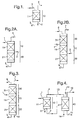
- Liquid feedstock is introduced via line 1 at the top of reaction zone 10 containing catalyst bed 11 and is distributed (means not shown) over the catalyst bed whilst a hydrogen-containing gas is introduced via line 2 below catalyst bed 11 in reaction zone 10 and rises up through the catalyst bed.
- Treated liquid is withdrawn from reaction zone 10 via line 3 and can be used as such or may be subjected to further processing/upgrading (not shown) and fluid depleted in hydrogen is withdrawn from reaction zone 10 via line 4 which can be cooled down in order to separate off liquid present therein (means not shown).
- the process as described in Figure 1 is carried out under conditions which allow a low Peclet number for the liquid in catalyst bed 11.
- the line-up as described in Figure 2B is that as described in Figure 2A with the addition of a further reaction zone 30 containing catalyst bed 31 above reaction zone 10 containing catalyst bed 11.
- Catalyst bed 31 is operated in trickle flow mode (high Peclet number of the liquid) and fluid depleted in hydrogen is withdrawn via line 7 which can be cooled down in order to separate off liquid present therein (means not shown).
- liquid feedstock can be introduced additionally via line 8 on top of catalyst bed 31 in reaction zone 30.
- Liquid feedstock is introduced via line 1 at the top of reaction zone 10 containing catalyst bed 11 and is distributed (means not shown) over the catalyst bed whilst a hydrogen-containing gas is introduced via line 2 below catalyst bed 11 in reaction zone 10 and rises up through catalyst bed 11.
- Treated liquid is withdrawn from reaction zone 10 and sent (at least partially) via line 3 to be combined with fluid depleted in hydrogen which has been (at least partially) withdrawn from reaction zone 10 via line 4. It is, of course, possible and preferred in practice, to allow part of the fluid exiting reaction zone 10 via line 4 to be condensed so that a gas/liquid mixture will be combined with treated fluid ex line 3 to form feedstock entering reaction zone 40 via line 13.
- the mixture is thus sent via line 13 to reaction zone 40 containing catalyst bed 41 which is operated (as hydroprocessing unit) in trickle flow mode (high Peclet number of the liquid).
- the hydrogen required for this part of the process can be supplied via line 14 at the top of reaction zone 40, thereby allowing for cocurrent hydroprocessing of the mixture entering reaction zone 40 via line 13, or via line 14 at the bottom of reaction zone 40 thereby causing the catalyst bed 41 to be operated in countercurrent mode.
- Treated liquid is withdrawn via line 15 and fluid depleted in hydrogen is withdrawn via line 16.
- a heavy gas oil was led downwardly through the catalyst bed and hydrogen was led via the bottom part of the catalyst bed in countercurrent to the heavy gas oil.
- the catalyst bed was loaded in such a way that the void fraction was 0.45.
- the Initial Boiling Point (IBP) of the gas oil was 230 °C; 62% boiled above 340 °C and its Final Boiling Point (FBP) was 450 °C. It contained 2.1 %wt of sulphur and 317 ppm of nitrogen.
- the conditions as pertaining in experiment 2 can be described as flooded countercurrent yielding a Peclet number of the liquid of 6 (calculated using the Westerterp reference referred to hereinabove).
Landscapes
- Chemical & Material Sciences (AREA)
- Oil, Petroleum & Natural Gas (AREA)
- Engineering & Computer Science (AREA)
- Chemical Kinetics & Catalysis (AREA)
- General Chemical & Material Sciences (AREA)
- Organic Chemistry (AREA)
- Production Of Liquid Hydrocarbon Mixture For Refining Petroleum (AREA)
- Devices And Processes Conducted In The Presence Of Fluids And Solid Particles (AREA)
- Cyclones (AREA)
- Separation Using Semi-Permeable Membranes (AREA)
- Extraction Or Liquid Replacement (AREA)
Abstract
Description
- The present invention is concerned with a method for hydroprocessing a hydrocarbonaceous feedstock at elevated temperature and pressure to obtain products, in particular fuels and/or middle distillates, which can be obtained in rather high yields at relatively low hydrogen consumption.
- Hydroprocessing is well known in the art and has been practiced for many years and is still one of the important refinery processes. Over the years, a variety of feedstocks, catalysts and process conditions have been described for hydroprocessing of which many have been put into practice. For instance, in hydrocracking it is customary to pass the feedstock to be hydrocracked together with a hydrogen-containing gas over a catalyst bed containing a fixed array of particles containing one or more metal compounds having an intrinsic capability for breaking carbon-carbon bonds as well as one or more metal compounds having an intrinsic capability of hydrogenating fragments present after the cracking operation has been performed.
- The method of hydrocracking in which a feedstock and a hydrogen-containing gas are passed through the catalyst bed in the same direction, normally from top to bottom to make use of the gravity force, is known as co-current hydroprocessing. It is the oldest commercially applied hydrocracking method which is still in operation.
- In the early 70's it has been suggested to operate hydrotreating processes in so-called "split flow" mode. In such processes, described inter alia in
US 3,607,723 ,US 3,671,420 andUS 3,897,329 , the feedstock is invariably introduced between two catalyst beds in a reaction zone whilst hydrogen is introduced from the bottom of the catalyst bed over which the feedstock is being distributed to be passed downwardly through the catalyst bed. In essence, the process carried out in the downstream bed (seen from the point of entry of the feedstock) is operated in countercurrent mode (feedstock moving downward meeting uprising hydrogen) whilst the process carried out in the catalyst bed above the catalyst bed over which the feedstock is being distributed is carried out in cocurrent mode (uprising hydrogen and fluid stripped by the uprising hydrogen moving in the same direction). In such "split flow" processes, use has to be made of two reaction zones which are preferably operated under the same process conditions. -
EP 287 234 EP 287 234 EP 287 234 - Although it was recognised that operating in countercurrent mode may provide some alleviation of flow maldistribution of the mixed phase present in cocurrent flow, there is nevertheless a major constraint which severely affects countercurrent hydroprocessing.
- A major constraint in countercurrent hydroprocessing is the risk that conventional fixed bed reactors are susceptible to a phenomenon normally referred to as "catalyst bed flooding" which will occur when the velocity of the upflowing hydrogen-containing gas is such that it prevents the downward gravitational flow of the feedstock to be hydroprocessed during its passage through the catalyst bed. Although catalyst contacting might improve as the bed approaches a flooded condition, it also makes the process rather vulnerable towards fluctuations in pressure or temperature or in fluid flow rates. Should a disturbance occur which is capable of initiating flooding it would cause disruption of the process, even to the extent of an unscheduled shutdown in order to recover stable operation.
- In order to minimise the occurrence of flooding in reactors operating in countercurrent mode it has been proposed, inter alia in patent publication
WO 99/00181 - It has been described in
US 4,775,281 , which is directed at the treatment of heavy hydrocarbons in countercurrent mode with specific froth control, that achievement of uniform vertical flow through a porous bed of solids can be obtained if the catalyst is properly distributed and shaped. The teaching ofUS 4,775,281 is specifically that the use of a densely packed bed of (spherical) solids (causing the reaction zone to have a low void fraction) would be advantageous in terms of catalyst concentration, but there might well be interference with fluid flow, especially when countercurrentflow of two phases is required. Therefore, it is strongly recommended in said patent specification that the catalyst bed to be used has a high void volume, typically greater than one-half of the bed. By using loosely packed polylobal or cylindrical extrudates void fractions from 0.5 to 0.9 can be achieved. This means a large sacrifice with respect to available reactor volume (at least half of the reactor volume cannot be filled with catalyst particles) which tremendously affects the yield of the envisaged process. - It has now been found that countercurrent hydroprocessing can be carried out in reaction zones having a lower void fraction and which do not require specific means for preventing flooding of the catalyst bed. The countercurrent hydroprocessing method according to the present invention is preferably carried out under flooding conditions. It also allows a higher yield than is achievable in cocurrent hydroprocessing. It has also been found that the process in accordance with the present invention allows a lower consumption of expensive hydrogen, a higher heavy ends conversion and a higher selectivity in the sulphur removal of higher boiling sulphur containing components.
- The present invention therefore relates to a method for the hydroprocessing of a heavy hydrocarbonaceous feedstock in a reaction zone comprising a bed containing a fixed array of porous catalyst particles by contacting the feedstock with a hydrogen-containing gas under conditions which allow distributing the feedstock predominantly in liquid phase under superatmospheric process conditions at elevated temperature over the catalyst bed for downward flow in contact with the catalyst particles and introduction of the hydrogen-containing gas in the reaction zone below the catalyst bed in order to establish countercurrent contact of the upwardly flowing gas with the downcoming liquid and withdrawing treated liquid below the catalyst bed and withdrawing fluid depleted in hydrogen above the catalyst bed, in which process the catalyst bed has a void volume fraction below 0.5, whilst the countercurrent liquid/gas contacting is carried out under conditions which allow the Peclet number of the liquid to be in the range between 0 and 10.
- Without wishing to be bound to any particular theory, it would appear that operating in a gas/liquid regime characterised by a low Peclet number of the liquid(i.e. by allowing a certain amount of liquid backmixing) allows the use of relatively dense-packed catalyst particles which therefore substantially increases the yield of the desired products. In other words: by providing process conditions which reduce the amount of static liquid hold up and thereby increase the amount of dynamic liquid hold up, unwanted reactions are diminished and more middle distillates are produced than otherwise would be the case. The combination of using a lower void fraction of the catalyst and a reduced ratio of the static and dynamic hold up of the liquid phase allows for improved performance in countercurrent hydroprocessing.
- Parameters which can be instrumental in providing countercurrent liquid/gas contacting comprise, inter alia, the gas rate (an increased gas rate reducing the unwanted static hold up), the liquid flow and the size of the restrictions in the introduction means for the gas. Those skilled in the art will know how to apply one or more of such parameters to allow for the appropriate Peclet number to be reached in the countercurrent hydroprocessing method according to the present invention.
- The void volume fraction of a catalyst bed is defined for the purposes of this invention as 'one minus the fraction of the volume occupied by the catalyst particles of the total volume of the reaction zone'. It will be clear that the internal pore volume of the solid catalyst particles is not included in the definition of the void volume fraction which is built up of the interstitial voids between the catalyst particles and between the appropriate catalyst particles and the walls of the reaction zone in which they are contained.
- Suitably, void volume fractions of catalyst beds above 0.25 (and below 0.50) can be used in the method according to the present invention. Preferred values are in the range between 0.30 and 0.48, especially preferred values are in the range between 0.35 and 0.47. Impressive results have been obtained using catalyst particles which have been packed in such a way that the void volume fraction is 0.45 (whilst operating under conditions allowing for the Peclet number of the liquid to be between 0 and 10).
- The Peclet number for systems in which liquids and gases come into contact with each other whilst the solid phase is fixed, as is the case in hydroprocessing using fixed arrays of porous solid catalyst particles, can be defined as the ratio between the transport rate by convection and the transport rate by dispersion; Chemical Reactor Design and Operation. K. Westerterp et. al. ISBN 0 471 90183 0. The Peclet number for a totally back-mixed system (normally occurring when operating under CSTR conditions - CSTR meaning Continuously Stirred Tank Reactor) is defined as 0 whilst the Peclet number of a system operating in plug flow (e.g. in conventional trickle flow hydrocracking) in which by definition backflow is absent is defined as infinite (∞). The preferred range for the Peclet number of the liquid in the method of the present invention is between 1 and 8. It will be clear to those skilled in the art how to calculate the actual Peclet number for a given situation. As stated hereinbefore, it is the combination of the use of a catalyst bed having a low void fraction under conditions which allow a low Peclet number of the liquid which allow for the improved performance of the hydroprocessing method according to the present invention.
- The catalysts to be used in the hydroprocessing method according to the present invention are well known in the art. They normally contain one or more metal(s) of Group VI and/or one or more non-noble metal(s) of Group VIII of the Periodic Table of the Elements which are conveniently present as oxides and/or as sulphides. Suitable Group VI elements are molybdenum and tungsten; suitable Group VIII metals are nickel and cobalt. The amounts of the metal compound(s) to be used can vary between wide ranges. Suitable ranges are between 2 and 40% by weight of Group VI metal compounds, expressed as metal, and between 1 and 10% by weight of Group VIII metal compounds, expressed as metal.
- Normally the catalyst particles will have the catalytically active metals present on a carrier. Suitable carrier materials are inorganic refractory oxides such as alumina, silica, silica-alumina. magnesia, titania, zirconia and mixtures of two or more of such materials. Advantageously, the catalyst particles may (additionally) contain dedicated cracking components such as zeolites and/or amorphous silica-alumina. Examples of suitable cracking components are well known in the art. Suitable zeolites comprise zeolite Y and zeolite β but also non-zeolitic components can be used such as (silico)-alumino phosphates and related compounds.
- A wide variety of catalyst shapes can be used in the method of hydroprocessing according to the present invention, such as spherical particles, cylindrical particles and polylobal particles such as trilobes and quadrulobes. Good results have been obtained using trilobal catalyst particles. Particles having a largest diameter between 0.5 and 3.5 mm are preferably applied. Good results have been obtained using trilobal catalyst particles having a diameter of 1.6 mm.
- The hydroprocessing method according to the present invention can be conveniently carried out using a temperature in the range between 200 °C and 475 °C, preferably in the range between 250 °C and 425 °C and at a pressure between 20 and 250 bar, preferably between 40 and 160 bar. The process can be carried out at a LHSV in the range between 1 and 20 Nl feed/l catalyst/hr and at a hydrogen/hydrocarbon feed ratio in the range between 100 and 2000 N1/1, preferably between 250 and 1500 N1/1. It will be clear that the set of process conditions has to be chosen in such a way that it allows the Peclet number of the liquid to be in the range between 0 and 10 (the void volume fraction of the catalyst bed in the reaction zone being less than 0.5 as discussed hereinbefore).
- Heavy hydrocarbonaceous feedstocks to be used in the method according to the present invention comprise the usual feedstocks which are commercially used in hydrocracking such as heavy gas oils and the like. Suitable feedstocks have an initial boiling point of at least 200 °C whilst feedstocks containing substantial amounts of material boiling above 520 °C, e.g. containing up to 40% by weight of such material, can also be processed satisfactorily.
- Commercially available hydrogen can be suitably used in the method according to the present invention. It may contain indigenous impurities to an extent that they do not substantially affect the catalytic activity. Hydrogen streams containing at least 50% by volume of hydrogen, especially at least 80% by volume, are preferred for duty in the present method. Normal impurities comprise light hydrocarbons and nitrogen.
- There are a number of process configurations which can be used advantageously in the method according to the present invention. Five line-ups of particular interest are described hereinbelow but those skilled in the art will recognise that equivalent line-ups can also be used. In Figure 1 the basic line-up is described for countercurrent hydroprocessing. A first and second preferred line-up are described in Figures 2A and 2B, a third preferred line-up is described in Figure 3 and a fourth preferred line-up is described in Figure 4. The same numerals have been used for the same parts in each of the Figures.
- Liquid feedstock is introduced via line 1 at the top of
reaction zone 10 containingcatalyst bed 11 and is distributed (means not shown) over the catalyst bed whilst a hydrogen-containing gas is introduced vialine 2 belowcatalyst bed 11 inreaction zone 10 and rises up through the catalyst bed. Treated liquid is withdrawn fromreaction zone 10 vialine 3 and can be used as such or may be subjected to further processing/upgrading (not shown) and fluid depleted in hydrogen is withdrawn fromreaction zone 10 vialine 4 which can be cooled down in order to separate off liquid present therein (means not shown). The process as described in Figure 1 is carried out under conditions which allow a low Peclet number for the liquid incatalyst bed 11. - The line-up as described in Figure 1 is extended by the presence of a
further reaction zone 20 containingcatalyst bed 21 downstream ofcatalyst bed 11 whichcatalyst bed 21 allows operation under trickle flow conditions (i.e. under conditions generating a high Peclet number for the liquid phase). Treated liquid emanating from the bottom ofreaction zone 10 is passed throughcatalyst bed 21 inreaction zone 20 and withdrawn there from vialine 5. It can be used as such or be subjected to further treatment (not shown). In this line-up there is no separate inlet for a hydrogen-containing gas (but it may be present if desired). - The line-up as described in Figure 2B is that as described in Figure 2A with the addition of a
further reaction zone 30 containingcatalyst bed 31 abovereaction zone 10 containingcatalyst bed 11.Catalyst bed 31 is operated in trickle flow mode (high Peclet number of the liquid) and fluid depleted in hydrogen is withdrawn vialine 7 which can be cooled down in order to separate off liquid present therein (means not shown). Optionally, liquid feedstock can be introduced additionally vialine 8 on top ofcatalyst bed 31 inreaction zone 30. - The line-up as described in Figure 2B is changed to the extent that the hydrogen-containing fluid is not introduced via
line 2 but vialine 12 at the bottom ofreaction zone 20 containingcatalyst bed 21. This line-up enables the process to be carried out in countercurrent mode with respect tocatalyst beds catalyst bed 31 is operated in trickle flow mode. It is possible to operatebed 21 and/orbed 11 under flooded conditions. - Liquid feedstock is introduced via line 1 at the top of
reaction zone 10 containingcatalyst bed 11 and is distributed (means not shown) over the catalyst bed whilst a hydrogen-containing gas is introduced vialine 2 belowcatalyst bed 11 inreaction zone 10 and rises up throughcatalyst bed 11. Treated liquid is withdrawn fromreaction zone 10 and sent (at least partially) vialine 3 to be combined with fluid depleted in hydrogen which has been (at least partially) withdrawn fromreaction zone 10 vialine 4. It is, of course, possible and preferred in practice, to allow part of the fluid exitingreaction zone 10 vialine 4 to be condensed so that a gas/liquid mixture will be combined with treatedfluid ex line 3 to form feedstock enteringreaction zone 40 vialine 13. The mixture is thus sent vialine 13 toreaction zone 40 containing catalyst bed 41 which is operated (as hydroprocessing unit) in trickle flow mode (high Peclet number of the liquid). The hydrogen required for this part of the process can be supplied vialine 14 at the top ofreaction zone 40, thereby allowing for cocurrent hydroprocessing of the mixture enteringreaction zone 40 vialine 13, or vialine 14 at the bottom ofreaction zone 40 thereby causing the catalyst bed 41 to be operated in countercurrent mode. Treated liquid is withdrawn vialine 15 and fluid depleted in hydrogen is withdrawn via line 16. - The method according to the present invention will now be elucidated by the following, non-limiting
- In a cylindrical reactor (lay out as depicted in Figure 1) having a length of 65 cm and an internal diameter of 2 cm and containing 1.6 mm trilobal catalyst particles (composed of 20 %wt of ultra stable zeolite Y and 80 %wt of alumina-based silica-alumina containing 4 %wt of Ni and 17 %wt of W as hydrogenation components) a heavy gas oil was led downwardly through the catalyst bed and hydrogen was led via the bottom part of the catalyst bed in countercurrent to the heavy gas oil. The catalyst bed was loaded in such a way that the void fraction was 0.45. The Initial Boiling Point (IBP) of the gas oil was 230 °C; 62% boiled above 340 °C and its Final Boiling Point (FBP) was 450 °C. It contained 2.1 %wt of sulphur and 317 ppm of nitrogen.
- Two experiments were carried out which differed only in the hydrogen gas rate applied. The details of
experiments 1 and 2 are given in Table I below.Table I Experiment 1 Experiment 2Space velocity Kg/l/h 0.75 0.75 H2 gas rate Nl/h 250 1000 Reactor pressure barg 40 40 Bed temperature °C 390 390 Peclet number of the liquid plug flow (*) 6 Conversion of 340 °C+ % 28.6 45.0 Selectivity to 150-340 °C % 86.0 92.1 *) Under the conditions as pertaining in experiment 1 the process was carried out in a conventional trickle flow mode which is normally referred to as "plug flow" (see: Advantages, Possibilities and Limitations of Small Scale Testing of Catalysts for Fixed-Bed Processes: S.T. Sie, 210th National Meeting, American Chemical Society, Chicago, Ill., August 20-25, 1995, p 463-472). A Peclet number of the liquid of 16 emanates from this setup. - The conditions as pertaining in
experiment 2 can be described as flooded countercurrent yielding a Peclet number of the liquid of 6 (calculated using the Westerterp reference referred to hereinabove). - It can be seen that under conditions which allow a low Peclet number (in accordance with the present invention) not only the conversion of the 340 °C+ part of the feedstock (i.e. the fraction of the feedstock boiling between 340 °C and 450 °C) has been increased substantially (by almost 50%) but that at the same time also the selectivity to desired product has increased from 86.0% to 92.1%.
- The experiments as described in Example 1 were repeated at a different space velocity under otherwise directly comparable conditions. The details of
experiments Table II Experiment 3Experiment 4Space velocity Kg/l/h 1.25 1.25 H2 gas rate Nl/h 250 1000 Reactor pressure barg 40 40 Bed temperature °C 390 390 Peclet number of the liquid plug flow (*) 2 Conversion of 340 °C+ % 19.3 37.0 Selectivity to 150-340 °C % 94.9 95.9 *) see the comments under Table I. - It can be seen that the same trend is found when operating at a higher space velocity; in particular it should be noted that the conversion can be doubled whilst still gaining in selectivity to the desired product.
Claims (10)
- Method for the hydroprocessing of a heavy hydrocarbonaceous feedstock in a reaction zone comprising a bed containing a fixed array of porous catalyst particles by contacting the feedstock with a hydrogen-containing gas under conditions which allow distributing the feedstock predominantly in liquid phase under superatmospheric process conditions at elevated temperature over the catalyst bed for downward flow in contact with the catalyst particles and introduction of the hydrogen-containing gas in the reaction zone below the catalyst bed in order to establish countercurrent contact of the upwardly flowing gas with the downcoming liquid and withdrawing treated liquid below the catalyst bed and withdrawing fluid depleted in hydrogen above the catalyst bed, in which process the catalyst bed has a void volume fraction below 0.5, whilst the countercurrent liquid/gas contacting is carried out under conditions which allow the Peclet number of the liquid to be in the range between 0 and 10.
- Method according to claim 1, in which the catalyst bed has a void volume fraction above 0.25.
- Method according to claim 2, in which the catalyst bed has a void volume fraction between 0.30 and 0.48, preferably between 0.35 and 0.47.
- Method according to any one of the preceding claims, in which the countercurrent contacting is carried out under conditions which allow the Peclet number of the liquid to be in the range between 1 and 8.
- Method according to any one of the preceding claims, in which treated liquid which has passed downwardly through the catalyst bed is passed in trickle flow mode through a further bed containing catalytic particles prior to its withdrawal from the process
- Method according to any of the preceding claims, in which fluid depleted in hydrogen which has passed upwardly through the catalyst bed is passed upwardly in vapour phase through a further bed containing catalytic particles prior to its withdrawal from the process as fluid depleted in hydrogen.
- Method according to claim 6, in which at least part of the upwardly flowing hydrogen-containing gas is introduced in the bottom of the reaction zone containing a further bed containing catalytic particles through which treated liquid is passed prior to its withdrawal from the process.
- Method according to any one of claims 1 to 6, in which at least part of the treated liquid and at least part of the fluid depleted in hydrogen are combined and subjected to a second hydroprocessing step which is carried out either cocurrently or counter currently.
- Method according to any one of the preceding claims, in which the hydroprocessing is carried out under hydrocracking conditions, including a temperature in the range between 200 °C and 475 °C and a pressure between 20 and 250 bar.
- Method according to claim 9, in which catalyst particles are used having a spherical, cylindrical or polylobal form and a largest diameter between 0.5 and 3.5 mm.
Priority Applications (1)
| Application Number | Priority Date | Filing Date | Title |
|---|---|---|---|
| EP02787711A EP1453937B1 (en) | 2001-11-16 | 2002-11-15 | Countercurrent hydroprocessing |
Applications Claiming Priority (4)
| Application Number | Priority Date | Filing Date | Title |
|---|---|---|---|
| EP01309668 | 2001-11-16 | ||
| EP01309668 | 2001-11-16 | ||
| PCT/EP2002/012856 WO2003042333A1 (en) | 2001-11-16 | 2002-11-15 | Countercurrent hydroprocessing |
| EP02787711A EP1453937B1 (en) | 2001-11-16 | 2002-11-15 | Countercurrent hydroprocessing |
Publications (2)
| Publication Number | Publication Date |
|---|---|
| EP1453937A1 EP1453937A1 (en) | 2004-09-08 |
| EP1453937B1 true EP1453937B1 (en) | 2007-08-01 |
Family
ID=8182463
Family Applications (1)
| Application Number | Title | Priority Date | Filing Date |
|---|---|---|---|
| EP02787711A Expired - Lifetime EP1453937B1 (en) | 2001-11-16 | 2002-11-15 | Countercurrent hydroprocessing |
Country Status (15)
| Country | Link |
|---|---|
| US (1) | US20050000858A1 (en) |
| EP (1) | EP1453937B1 (en) |
| JP (1) | JP2005509083A (en) |
| KR (1) | KR20050044435A (en) |
| CN (1) | CN1309808C (en) |
| AT (1) | ATE368718T1 (en) |
| AU (1) | AU2002352037B2 (en) |
| BR (1) | BR0214086A (en) |
| CA (1) | CA2467094A1 (en) |
| DE (1) | DE60221564T2 (en) |
| MX (1) | MXPA04004652A (en) |
| NO (1) | NO20042496L (en) |
| RU (1) | RU2288253C2 (en) |
| WO (1) | WO2003042333A1 (en) |
| ZA (1) | ZA200403161B (en) |
Families Citing this family (18)
| Publication number | Priority date | Publication date | Assignee | Title |
|---|---|---|---|---|
| US7435336B2 (en) * | 2002-10-10 | 2008-10-14 | China Petroleum & Chenical Corporation | Process for carrying out gas-liquid countercurrent processing |
| US7879223B2 (en) | 2003-12-19 | 2011-02-01 | Shell Oil Company | Systems and methods of producing a crude product |
| EP2526898B1 (en) * | 2003-12-23 | 2013-04-17 | Sadra Medical, Inc. | Repositionable heart valve |
| US20050137694A1 (en) | 2003-12-23 | 2005-06-23 | Haug Ulrich R. | Methods and apparatus for endovascularly replacing a patient's heart valve |
| US7354507B2 (en) | 2004-03-17 | 2008-04-08 | Conocophillips Company | Hydroprocessing methods and apparatus for use in the preparation of liquid hydrocarbons |
| DE102005003632A1 (en) | 2005-01-20 | 2006-08-17 | Fraunhofer-Gesellschaft zur Förderung der angewandten Forschung e.V. | Catheter for the transvascular implantation of heart valve prostheses |
| US7422904B2 (en) | 2005-02-04 | 2008-09-09 | Exxonmobil Chemical Patents Inc. | Method of operating a fixed bed reactor under predetermined hydraulic conditions |
| US7896915B2 (en) | 2007-04-13 | 2011-03-01 | Jenavalve Technology, Inc. | Medical device for treating a heart valve insufficiency |
| ES2903231T3 (en) | 2008-02-26 | 2022-03-31 | Jenavalve Tech Inc | Stent for positioning and anchoring a valve prosthesis at an implantation site in a patient's heart |
| US9044318B2 (en) | 2008-02-26 | 2015-06-02 | Jenavalve Technology Gmbh | Stent for the positioning and anchoring of a valvular prosthesis |
| US8313705B2 (en) * | 2008-06-23 | 2012-11-20 | Uop Llc | System and process for reacting a petroleum fraction |
| JP2013526388A (en) | 2010-05-25 | 2013-06-24 | イエナバルブ テクノロジー インク | Artificial heart valve, and transcatheter delivery prosthesis comprising an artificial heart valve and a stent |
| US9365781B2 (en) | 2012-05-25 | 2016-06-14 | E I Du Pont De Nemours And Company | Process for direct hydrogen injection in liquid full hydroprocessing reactors |
| JP6563394B2 (en) | 2013-08-30 | 2019-08-21 | イェーナヴァルヴ テクノロジー インコーポレイテッド | Radially foldable frame for an artificial valve and method for manufacturing the frame |
| CN107530168B (en) | 2015-05-01 | 2020-06-09 | 耶拿阀门科技股份有限公司 | Device and method with reduced pacemaker ratio in heart valve replacement |
| EP3454795B1 (en) | 2016-05-13 | 2023-01-11 | JenaValve Technology, Inc. | Heart valve prosthesis delivery system for delivery of heart valve prosthesis with introducer sheath and loading system |
| JP7094965B2 (en) | 2017-01-27 | 2022-07-04 | イエナバルブ テクノロジー インク | Heart valve imitation |
| CN113198624B (en) * | 2021-05-08 | 2022-03-01 | 华东理工大学 | Method and device for strong mass transfer countercurrent contact of two-phase fluid |
Family Cites Families (5)
| Publication number | Priority date | Publication date | Assignee | Title |
|---|---|---|---|---|
| EP0287234A1 (en) * | 1987-04-14 | 1988-10-19 | Mobil Oil Corporation | Multi-phase countercurrent hydrodewaxing process |
| US5578197A (en) * | 1989-05-09 | 1996-11-26 | Alberta Oil Sands Technology & Research Authority | Hydrocracking process involving colloidal catalyst formed in situ |
| DE69404320T2 (en) * | 1993-10-08 | 1998-01-29 | Akzo Nobel Nv | HYDROCRACK AND HYDRODEWAX PROCESS |
| US5985135A (en) * | 1998-10-23 | 1999-11-16 | Exxon Research And Engineering Co. | Staged upflow and downflow hydroprocessing with noncatalytic removal of upflow stage vapor impurities |
| FR2806642B1 (en) * | 2000-03-27 | 2002-08-23 | Inst Francais Du Petrole | PROCESS FOR CONVERTING HYDROCARBONS IN A THREE-PHASE REACTOR |
-
2002
- 2002-11-15 KR KR1020047007237A patent/KR20050044435A/en not_active Application Discontinuation
- 2002-11-15 CA CA002467094A patent/CA2467094A1/en not_active Abandoned
- 2002-11-15 CN CNB028227263A patent/CN1309808C/en not_active Expired - Fee Related
- 2002-11-15 BR BR0214086-1A patent/BR0214086A/en not_active IP Right Cessation
- 2002-11-15 AU AU2002352037A patent/AU2002352037B2/en not_active Ceased
- 2002-11-15 MX MXPA04004652A patent/MXPA04004652A/en active IP Right Grant
- 2002-11-15 AT AT02787711T patent/ATE368718T1/en not_active IP Right Cessation
- 2002-11-15 US US10/495,596 patent/US20050000858A1/en not_active Abandoned
- 2002-11-15 JP JP2003544153A patent/JP2005509083A/en active Pending
- 2002-11-15 EP EP02787711A patent/EP1453937B1/en not_active Expired - Lifetime
- 2002-11-15 WO PCT/EP2002/012856 patent/WO2003042333A1/en active IP Right Grant
- 2002-11-15 DE DE60221564T patent/DE60221564T2/en not_active Expired - Fee Related
- 2002-11-15 RU RU2004118073/04A patent/RU2288253C2/en active IP Right Revival
-
2004
- 2004-04-26 ZA ZA200403161A patent/ZA200403161B/en unknown
- 2004-06-15 NO NO20042496A patent/NO20042496L/en not_active Application Discontinuation
Non-Patent Citations (1)
| Title |
|---|
| None * |
Also Published As
| Publication number | Publication date |
|---|---|
| RU2288253C2 (en) | 2006-11-27 |
| DE60221564D1 (en) | 2007-09-13 |
| DE60221564T2 (en) | 2008-04-17 |
| US20050000858A1 (en) | 2005-01-06 |
| ATE368718T1 (en) | 2007-08-15 |
| MXPA04004652A (en) | 2004-08-13 |
| CA2467094A1 (en) | 2003-05-22 |
| RU2004118073A (en) | 2006-01-10 |
| CN1589310A (en) | 2005-03-02 |
| KR20050044435A (en) | 2005-05-12 |
| JP2005509083A (en) | 2005-04-07 |
| AU2002352037B2 (en) | 2007-05-17 |
| EP1453937A1 (en) | 2004-09-08 |
| NO20042496L (en) | 2004-06-15 |
| BR0214086A (en) | 2004-09-28 |
| WO2003042333A1 (en) | 2003-05-22 |
| ZA200403161B (en) | 2005-01-14 |
| CN1309808C (en) | 2007-04-11 |
Similar Documents
| Publication | Publication Date | Title |
|---|---|---|
| EP1453937B1 (en) | Countercurrent hydroprocessing | |
| JP4074667B2 (en) | Multi-stage hydroprocessing method in a single reactor | |
| JP4150432B2 (en) | Counter-current reactor | |
| AU2002352037A1 (en) | Countercurrent hydroprocessing | |
| US7507325B2 (en) | Process for converting heavy petroleum fractions for producing a catalytic cracking feedstock and middle distillates with a low sulfur content | |
| US20110094938A1 (en) | Process for the conversion of residue integrating moving-bed technology and ebullating-bed technology | |
| EP2782977B1 (en) | Slurry bed hydroprocessing and system | |
| EP0944692B1 (en) | Hydroprocessing in a countercurrent reaction vessel | |
| EP0272038B1 (en) | Method for hydrocracking heavy fraction oils | |
| US20030089638A1 (en) | Process for converting heavy petroleum fractions including an ebulliated bed for producing middle distillates with a low sulfur content | |
| WO1998007490A1 (en) | Countercurrent reaction vessel | |
| US3556989A (en) | Hydrocarbon oil treatment process and apparatus therefor | |
| CN113383057B (en) | Two-stage hydrocracking process for producing naphtha comprising a hydrogenation step carried out downstream of a second hydrocracking step | |
| EP0354626B1 (en) | Process for the hydrocracking of a hydrocarbonaceous feedstock | |
| CN100381543C (en) | Hydrocracking method for composite catalyst bed layer | |
| EP0354623B1 (en) | Process for the hydrocracking of a hydrocarbonaceous feedstock | |
| JP2002322484A (en) | Hydrogenating process | |
| CN113557289A (en) | Two-step hydrocracking process for the production of middle distillates comprising a hydrogenation step downstream of the second hydrocracking step | |
| CN112342058A (en) | Method and system for treating catalytic cracking slurry oil | |
| US11084991B2 (en) | Two-phase moving bed reactor utilizing hydrogen-enriched feed | |
| US3457161A (en) | Process for treatment of mineral oils | |
| WO1992001768A1 (en) | Hydrocarbon processing of gas containing feed in a countercurrent moving catalyst bed | |
| CN115124401A (en) | Method and system for producing more low-carbon olefins | |
| WO1994022982A1 (en) | Integrated hydrocracking/hydrotreating process |
Legal Events
| Date | Code | Title | Description |
|---|---|---|---|
| PUAI | Public reference made under article 153(3) epc to a published international application that has entered the european phase |
Free format text: ORIGINAL CODE: 0009012 |
|
| 17P | Request for examination filed |
Effective date: 20040427 |
|
| AK | Designated contracting states |
Kind code of ref document: A1 Designated state(s): AT BE BG CH CY CZ DE DK EE ES FI FR GB GR IE IT LI LU MC NL PT SE SK TR |
|
| AX | Request for extension of the european patent |
Extension state: AL LT LV MK RO SI |
|
| GRAP | Despatch of communication of intention to grant a patent |
Free format text: ORIGINAL CODE: EPIDOSNIGR1 |
|
| GRAS | Grant fee paid |
Free format text: ORIGINAL CODE: EPIDOSNIGR3 |
|
| GRAA | (expected) grant |
Free format text: ORIGINAL CODE: 0009210 |
|
| AK | Designated contracting states |
Kind code of ref document: B1 Designated state(s): AT BE BG CH CY CZ DE DK EE ES FI FR GB GR IE IT LI LU MC NL PT SE SK TR |
|
| REG | Reference to a national code |
Ref country code: GB Ref legal event code: FG4D |
|
| REG | Reference to a national code |
Ref country code: CH Ref legal event code: EP |
|
| REG | Reference to a national code |
Ref country code: IE Ref legal event code: FG4D |
|
| REF | Corresponds to: |
Ref document number: 60221564 Country of ref document: DE Date of ref document: 20070913 Kind code of ref document: P |
|
| ET | Fr: translation filed | ||
| PG25 | Lapsed in a contracting state [announced via postgrant information from national office to epo] |
Ref country code: BG Free format text: LAPSE BECAUSE OF FAILURE TO SUBMIT A TRANSLATION OF THE DESCRIPTION OR TO PAY THE FEE WITHIN THE PRESCRIBED TIME-LIMIT Effective date: 20071101 Ref country code: FI Free format text: LAPSE BECAUSE OF FAILURE TO SUBMIT A TRANSLATION OF THE DESCRIPTION OR TO PAY THE FEE WITHIN THE PRESCRIBED TIME-LIMIT Effective date: 20070801 Ref country code: ES Free format text: LAPSE BECAUSE OF FAILURE TO SUBMIT A TRANSLATION OF THE DESCRIPTION OR TO PAY THE FEE WITHIN THE PRESCRIBED TIME-LIMIT Effective date: 20071112 |
|
| REG | Reference to a national code |
Ref country code: CH Ref legal event code: PL |
|
| PG25 | Lapsed in a contracting state [announced via postgrant information from national office to epo] |
Ref country code: LI Free format text: LAPSE BECAUSE OF FAILURE TO SUBMIT A TRANSLATION OF THE DESCRIPTION OR TO PAY THE FEE WITHIN THE PRESCRIBED TIME-LIMIT Effective date: 20070801 Ref country code: CH Free format text: LAPSE BECAUSE OF FAILURE TO SUBMIT A TRANSLATION OF THE DESCRIPTION OR TO PAY THE FEE WITHIN THE PRESCRIBED TIME-LIMIT Effective date: 20070801 Ref country code: AT Free format text: LAPSE BECAUSE OF FAILURE TO SUBMIT A TRANSLATION OF THE DESCRIPTION OR TO PAY THE FEE WITHIN THE PRESCRIBED TIME-LIMIT Effective date: 20070801 |
|
| PG25 | Lapsed in a contracting state [announced via postgrant information from national office to epo] |
Ref country code: BE Free format text: LAPSE BECAUSE OF FAILURE TO SUBMIT A TRANSLATION OF THE DESCRIPTION OR TO PAY THE FEE WITHIN THE PRESCRIBED TIME-LIMIT Effective date: 20070801 |
|
| PG25 | Lapsed in a contracting state [announced via postgrant information from national office to epo] |
Ref country code: GR Free format text: LAPSE BECAUSE OF FAILURE TO SUBMIT A TRANSLATION OF THE DESCRIPTION OR TO PAY THE FEE WITHIN THE PRESCRIBED TIME-LIMIT Effective date: 20071102 Ref country code: DK Free format text: LAPSE BECAUSE OF FAILURE TO SUBMIT A TRANSLATION OF THE DESCRIPTION OR TO PAY THE FEE WITHIN THE PRESCRIBED TIME-LIMIT Effective date: 20070801 |
|
| PG25 | Lapsed in a contracting state [announced via postgrant information from national office to epo] |
Ref country code: CZ Free format text: LAPSE BECAUSE OF FAILURE TO SUBMIT A TRANSLATION OF THE DESCRIPTION OR TO PAY THE FEE WITHIN THE PRESCRIBED TIME-LIMIT Effective date: 20070801 Ref country code: PT Free format text: LAPSE BECAUSE OF FAILURE TO SUBMIT A TRANSLATION OF THE DESCRIPTION OR TO PAY THE FEE WITHIN THE PRESCRIBED TIME-LIMIT Effective date: 20080102 Ref country code: SK Free format text: LAPSE BECAUSE OF FAILURE TO SUBMIT A TRANSLATION OF THE DESCRIPTION OR TO PAY THE FEE WITHIN THE PRESCRIBED TIME-LIMIT Effective date: 20070801 |
|
| PLBE | No opposition filed within time limit |
Free format text: ORIGINAL CODE: 0009261 |
|
| STAA | Information on the status of an ep patent application or granted ep patent |
Free format text: STATUS: NO OPPOSITION FILED WITHIN TIME LIMIT |
|
| PG25 | Lapsed in a contracting state [announced via postgrant information from national office to epo] |
Ref country code: MC Free format text: LAPSE BECAUSE OF NON-PAYMENT OF DUE FEES Effective date: 20071130 Ref country code: SE Free format text: LAPSE BECAUSE OF FAILURE TO SUBMIT A TRANSLATION OF THE DESCRIPTION OR TO PAY THE FEE WITHIN THE PRESCRIBED TIME-LIMIT Effective date: 20071101 |
|
| 26N | No opposition filed |
Effective date: 20080506 |
|
| PG25 | Lapsed in a contracting state [announced via postgrant information from national office to epo] |
Ref country code: IE Free format text: LAPSE BECAUSE OF NON-PAYMENT OF DUE FEES Effective date: 20071115 |
|
| PGFP | Annual fee paid to national office [announced via postgrant information from national office to epo] |
Ref country code: FR Payment date: 20080919 Year of fee payment: 7 |
|
| PG25 | Lapsed in a contracting state [announced via postgrant information from national office to epo] |
Ref country code: EE Free format text: LAPSE BECAUSE OF FAILURE TO SUBMIT A TRANSLATION OF THE DESCRIPTION OR TO PAY THE FEE WITHIN THE PRESCRIBED TIME-LIMIT Effective date: 20070801 |
|
| PGFP | Annual fee paid to national office [announced via postgrant information from national office to epo] |
Ref country code: DE Payment date: 20081127 Year of fee payment: 7 Ref country code: NL Payment date: 20081127 Year of fee payment: 7 |
|
| PGFP | Annual fee paid to national office [announced via postgrant information from national office to epo] |
Ref country code: GB Payment date: 20081022 Year of fee payment: 7 |
|
| PG25 | Lapsed in a contracting state [announced via postgrant information from national office to epo] |
Ref country code: CY Free format text: LAPSE BECAUSE OF FAILURE TO SUBMIT A TRANSLATION OF THE DESCRIPTION OR TO PAY THE FEE WITHIN THE PRESCRIBED TIME-LIMIT Effective date: 20070801 |
|
| PG25 | Lapsed in a contracting state [announced via postgrant information from national office to epo] |
Ref country code: LU Free format text: LAPSE BECAUSE OF NON-PAYMENT OF DUE FEES Effective date: 20071115 |
|
| PG25 | Lapsed in a contracting state [announced via postgrant information from national office to epo] |
Ref country code: TR Free format text: LAPSE BECAUSE OF FAILURE TO SUBMIT A TRANSLATION OF THE DESCRIPTION OR TO PAY THE FEE WITHIN THE PRESCRIBED TIME-LIMIT Effective date: 20070801 |
|
| REG | Reference to a national code |
Ref country code: NL Ref legal event code: V1 Effective date: 20100601 |
|
| GBPC | Gb: european patent ceased through non-payment of renewal fee |
Effective date: 20091115 |
|
| REG | Reference to a national code |
Ref country code: FR Ref legal event code: ST Effective date: 20100730 |
|
| PG25 | Lapsed in a contracting state [announced via postgrant information from national office to epo] |
Ref country code: NL Free format text: LAPSE BECAUSE OF NON-PAYMENT OF DUE FEES Effective date: 20100601 Ref country code: FR Free format text: LAPSE BECAUSE OF NON-PAYMENT OF DUE FEES Effective date: 20091130 |
|
| PG25 | Lapsed in a contracting state [announced via postgrant information from national office to epo] |
Ref country code: DE Free format text: LAPSE BECAUSE OF NON-PAYMENT OF DUE FEES Effective date: 20100601 |
|
| PG25 | Lapsed in a contracting state [announced via postgrant information from national office to epo] |
Ref country code: GB Free format text: LAPSE BECAUSE OF NON-PAYMENT OF DUE FEES Effective date: 20091115 |
|
| PG25 | Lapsed in a contracting state [announced via postgrant information from national office to epo] |
Ref country code: IT Free format text: LAPSE BECAUSE OF NON-PAYMENT OF DUE FEES Effective date: 20071130 |