EP1453715B1 - Motorized cart with hub gear motor system - Google Patents
Motorized cart with hub gear motor system Download PDFInfo
- Publication number
- EP1453715B1 EP1453715B1 EP02789784.2A EP02789784A EP1453715B1 EP 1453715 B1 EP1453715 B1 EP 1453715B1 EP 02789784 A EP02789784 A EP 02789784A EP 1453715 B1 EP1453715 B1 EP 1453715B1
- Authority
- EP
- European Patent Office
- Prior art keywords
- gear
- cart
- motor
- front wheel
- leads
- Prior art date
- Legal status (The legal status is an assumption and is not a legal conclusion. Google has not performed a legal analysis and makes no representation as to the accuracy of the status listed.)
- Expired - Lifetime
Links
Images




Classifications
-
- B—PERFORMING OPERATIONS; TRANSPORTING
- B60—VEHICLES IN GENERAL
- B60K—ARRANGEMENT OR MOUNTING OF PROPULSION UNITS OR OF TRANSMISSIONS IN VEHICLES; ARRANGEMENT OR MOUNTING OF PLURAL DIVERSE PRIME-MOVERS IN VEHICLES; AUXILIARY DRIVES FOR VEHICLES; INSTRUMENTATION OR DASHBOARDS FOR VEHICLES; ARRANGEMENTS IN CONNECTION WITH COOLING, AIR INTAKE, GAS EXHAUST OR FUEL SUPPLY OF PROPULSION UNITS IN VEHICLES
- B60K7/00—Disposition of motor in, or adjacent to, traction wheel
- B60K7/0007—Disposition of motor in, or adjacent to, traction wheel the motor being electric
-
- B—PERFORMING OPERATIONS; TRANSPORTING
- B62—LAND VEHICLES FOR TRAVELLING OTHERWISE THAN ON RAILS
- B62B—HAND-PROPELLED VEHICLES, e.g. HAND CARTS OR PERAMBULATORS; SLEDGES
- B62B5/00—Accessories or details specially adapted for hand carts
- B62B5/0026—Propulsion aids
-
- B—PERFORMING OPERATIONS; TRANSPORTING
- B62—LAND VEHICLES FOR TRAVELLING OTHERWISE THAN ON RAILS
- B62K—CYCLES; CYCLE FRAMES; CYCLE STEERING DEVICES; RIDER-OPERATED TERMINAL CONTROLS SPECIALLY ADAPTED FOR CYCLES; CYCLE AXLE SUSPENSIONS; CYCLE SIDECARS, FORECARS, OR THE LIKE
- B62K5/00—Cycles with handlebars, equipped with three or more main road wheels
- B62K5/02—Tricycles
- B62K5/023—Tricycles specially adapted for disabled riders, e.g. personal mobility type vehicles with three wheels
- B62K5/025—Tricycles specially adapted for disabled riders, e.g. personal mobility type vehicles with three wheels power-driven
-
- B—PERFORMING OPERATIONS; TRANSPORTING
- B60—VEHICLES IN GENERAL
- B60K—ARRANGEMENT OR MOUNTING OF PROPULSION UNITS OR OF TRANSMISSIONS IN VEHICLES; ARRANGEMENT OR MOUNTING OF PLURAL DIVERSE PRIME-MOVERS IN VEHICLES; AUXILIARY DRIVES FOR VEHICLES; INSTRUMENTATION OR DASHBOARDS FOR VEHICLES; ARRANGEMENTS IN CONNECTION WITH COOLING, AIR INTAKE, GAS EXHAUST OR FUEL SUPPLY OF PROPULSION UNITS IN VEHICLES
- B60K1/00—Arrangement or mounting of electrical propulsion units
- B60K1/04—Arrangement or mounting of electrical propulsion units of the electric storage means for propulsion
-
- B—PERFORMING OPERATIONS; TRANSPORTING
- B60—VEHICLES IN GENERAL
- B60K—ARRANGEMENT OR MOUNTING OF PROPULSION UNITS OR OF TRANSMISSIONS IN VEHICLES; ARRANGEMENT OR MOUNTING OF PLURAL DIVERSE PRIME-MOVERS IN VEHICLES; AUXILIARY DRIVES FOR VEHICLES; INSTRUMENTATION OR DASHBOARDS FOR VEHICLES; ARRANGEMENTS IN CONNECTION WITH COOLING, AIR INTAKE, GAS EXHAUST OR FUEL SUPPLY OF PROPULSION UNITS IN VEHICLES
- B60K17/00—Arrangement or mounting of transmissions in vehicles
- B60K17/04—Arrangement or mounting of transmissions in vehicles characterised by arrangement, location or kind of gearing
- B60K17/043—Transmission unit disposed in on near the vehicle wheel, or between the differential gear unit and the wheel
-
- B—PERFORMING OPERATIONS; TRANSPORTING
- B60—VEHICLES IN GENERAL
- B60K—ARRANGEMENT OR MOUNTING OF PROPULSION UNITS OR OF TRANSMISSIONS IN VEHICLES; ARRANGEMENT OR MOUNTING OF PLURAL DIVERSE PRIME-MOVERS IN VEHICLES; AUXILIARY DRIVES FOR VEHICLES; INSTRUMENTATION OR DASHBOARDS FOR VEHICLES; ARRANGEMENTS IN CONNECTION WITH COOLING, AIR INTAKE, GAS EXHAUST OR FUEL SUPPLY OF PROPULSION UNITS IN VEHICLES
- B60K17/00—Arrangement or mounting of transmissions in vehicles
- B60K17/04—Arrangement or mounting of transmissions in vehicles characterised by arrangement, location or kind of gearing
- B60K17/043—Transmission unit disposed in on near the vehicle wheel, or between the differential gear unit and the wheel
- B60K17/046—Transmission unit disposed in on near the vehicle wheel, or between the differential gear unit and the wheel with planetary gearing having orbital motion
-
- B—PERFORMING OPERATIONS; TRANSPORTING
- B60—VEHICLES IN GENERAL
- B60K—ARRANGEMENT OR MOUNTING OF PROPULSION UNITS OR OF TRANSMISSIONS IN VEHICLES; ARRANGEMENT OR MOUNTING OF PLURAL DIVERSE PRIME-MOVERS IN VEHICLES; AUXILIARY DRIVES FOR VEHICLES; INSTRUMENTATION OR DASHBOARDS FOR VEHICLES; ARRANGEMENTS IN CONNECTION WITH COOLING, AIR INTAKE, GAS EXHAUST OR FUEL SUPPLY OF PROPULSION UNITS IN VEHICLES
- B60K1/00—Arrangement or mounting of electrical propulsion units
- B60K1/04—Arrangement or mounting of electrical propulsion units of the electric storage means for propulsion
- B60K2001/0405—Arrangement or mounting of electrical propulsion units of the electric storage means for propulsion characterised by their position
- B60K2001/0416—Arrangement in the rear part of the vehicle
-
- B—PERFORMING OPERATIONS; TRANSPORTING
- B60—VEHICLES IN GENERAL
- B60K—ARRANGEMENT OR MOUNTING OF PROPULSION UNITS OR OF TRANSMISSIONS IN VEHICLES; ARRANGEMENT OR MOUNTING OF PLURAL DIVERSE PRIME-MOVERS IN VEHICLES; AUXILIARY DRIVES FOR VEHICLES; INSTRUMENTATION OR DASHBOARDS FOR VEHICLES; ARRANGEMENTS IN CONNECTION WITH COOLING, AIR INTAKE, GAS EXHAUST OR FUEL SUPPLY OF PROPULSION UNITS IN VEHICLES
- B60K7/00—Disposition of motor in, or adjacent to, traction wheel
- B60K2007/0038—Disposition of motor in, or adjacent to, traction wheel the motor moving together with the wheel axle
-
- B—PERFORMING OPERATIONS; TRANSPORTING
- B60—VEHICLES IN GENERAL
- B60K—ARRANGEMENT OR MOUNTING OF PROPULSION UNITS OR OF TRANSMISSIONS IN VEHICLES; ARRANGEMENT OR MOUNTING OF PLURAL DIVERSE PRIME-MOVERS IN VEHICLES; AUXILIARY DRIVES FOR VEHICLES; INSTRUMENTATION OR DASHBOARDS FOR VEHICLES; ARRANGEMENTS IN CONNECTION WITH COOLING, AIR INTAKE, GAS EXHAUST OR FUEL SUPPLY OF PROPULSION UNITS IN VEHICLES
- B60K7/00—Disposition of motor in, or adjacent to, traction wheel
- B60K2007/0092—Disposition of motor in, or adjacent to, traction wheel the motor axle being coaxial to the wheel axle
-
- B—PERFORMING OPERATIONS; TRANSPORTING
- B62—LAND VEHICLES FOR TRAVELLING OTHERWISE THAN ON RAILS
- B62B—HAND-PROPELLED VEHICLES, e.g. HAND CARTS OR PERAMBULATORS; SLEDGES
- B62B3/00—Hand carts having more than one axis carrying transport wheels; Steering devices therefor; Equipment therefor
- B62B3/14—Hand carts having more than one axis carrying transport wheels; Steering devices therefor; Equipment therefor characterised by provisions for nesting or stacking, e.g. shopping trolleys
-
- B—PERFORMING OPERATIONS; TRANSPORTING
- B62—LAND VEHICLES FOR TRAVELLING OTHERWISE THAN ON RAILS
- B62B—HAND-PROPELLED VEHICLES, e.g. HAND CARTS OR PERAMBULATORS; SLEDGES
- B62B5/00—Accessories or details specially adapted for hand carts
- B62B5/0026—Propulsion aids
- B62B5/0033—Electric motors
- B62B5/0036—Arrangements of motors
- B62B5/004—Arrangements of motors in wheels
-
- B—PERFORMING OPERATIONS; TRANSPORTING
- B62—LAND VEHICLES FOR TRAVELLING OTHERWISE THAN ON RAILS
- B62K—CYCLES; CYCLE FRAMES; CYCLE STEERING DEVICES; RIDER-OPERATED TERMINAL CONTROLS SPECIALLY ADAPTED FOR CYCLES; CYCLE AXLE SUSPENSIONS; CYCLE SIDECARS, FORECARS, OR THE LIKE
- B62K15/00—Collapsible or foldable cycles
- B62K2015/005—Collapsible or foldable cycles having additional wheels for use when folded or collapsed
Definitions
- the present invention is directed to a hub gear motor system and to a motorized cart with a hub gear motor system.
- the motorized cart has at least one front wheel and at least one rear wheel.
- the front wheel of the motorized cart is driven by the hub gear motor system which comprises means for driving the cart body that is substantially contained within a casing of the front wheel.
- JP8310254 discloses a hub gear motor system according to the preamble of claim 13, and a motorized cart according to the preamble of claim 1.
- Motorized carts are commonly used in stores and homes to provide mobility for individuals that are unable to walk or stand for any length of time. Because of their size and large turning radius, these carts can be difficult to maneuver in an area with limited space. Due to such space limitations, most stores and homes are generally unable to accommodate such motorized carts without renovating or rearranging the area in which the carts are to be used.
- a drive train translates the rotational movement of the motor to one or both rear wheels.
- the drive train adds to the weight of the cart requiring that the amount of power to operate the cart be increased according to the weight added by the drive train thereby increasing the requisite size of the cart.
- a 24-volt battery system comprises a pair of 12-volt batteries. Not only is such a system more complex since the batteries are connected in a series, but batteries connected in a series are also difficult to consistently recharge. Typically, one of the batteries in a Series will overcharge and the other battery will fail to fully charge. Such a recharging routine is inefficient and can be frustrating for a user. It is not uncommon to improve these systems by providing a separate charger for each battery in the series. This can significantly increase the weight of the cart and increase the cost of manufacturing.
- One aspect of the cart's maneuverability can be determined by its turning radius. The smaller the turning radius the more maneuverable is the cart, making it easier to manage in small areas.
- a cart with rear wheel drive generally has a large turning radius. Because it is pushed by the movement of its rear wheels and continues to move forward throughout the duration of the turn. The cart's turning radius is greater than the length of the cart. As a result, carts having rear wheel drive are difficult and cumbersome to operate.
- Another drawback to a cart with rear wheel drive is that the front wheel (s) is subject to skipping or skidding across the floor's surface when cornering the cart. This typically occurs when making a sharp turn into the rear wheel that is powered combined with the front wheel not being aligned with the direction of the cart's movement (i.e., such as when the front wheel is turned to corner the cart). In these instances, the forward movement of the cart overcomes the turning motion of the front wheel and the front wheel is unable to rotate properly to guide the cart, resulting in the wheel skidding or skipping across the surface of the floor.
- the present invention is a motorized cart having a hub gear motor system according to claim 1.
- the motorized cart includes a cart body movably mounted on at least one rear wheel and at least one front wheel.
- the hub gear motor system includes a means for driving the cart which is substantially contained within a casing of the front wheel.
- the hub gear motor system further comprising means for controlling the driving means which rotates the at least one front wheel in forward and rearward directions to thereby move the motorized cart
- said hub gear motor system further comprising: an electric reversible motor with a rotor; an intermediate plate attached to the rotor; and first, second, third and fourth gears; wherein the first gear is attached to the rotor on the electric reversible motor and the fourth gear is adapted for fixed attachment to the front wheel, the first gear engages the second gear, the fourth gear engages the third gear, the first and fourth gears are rotatable about a first rotational axis, the second gear and third gears are rotatably mounted on the intermediate plate and rotate about a second rotational axis, the second rotational axis is offset from the first rotational axis, wherein said electric reversible motor, said intermediate plate and said first, second, third and fourth gears are adapted to be substantially contained within the casing of the front wheel wherein said first gear is rotated by the electric
- the present invention further defines a hub gear motor system according to claim 13.
- a motorized cart (1) with a hub gear motor system (2) The motorized cart (1) comprises a cart body (10).
- the hub gear motor system (2) includes means for driving the cart body, means for powering the driving means and means for controlling the driving means.
- the cart body (10) includes a platform (11) with a seat (12), a plurality of wheels, a steering unit (13) and a storage receptacle (14). As shown in Figure 2 , the cart body (10) also has a support frame (15) that provides an infrastructure for supporting the seat (12) and the platform (11).
- the support frame (15) itself is comprised of a plurality of longitudinal pieces and cross pieces.
- the support frame (15) also includes a column support bracket (17) which has an outer support surface (18) thereon.
- the steering unit (13) is shown to include a steering column (23) having two ends with a handle (24) at one of the ends. Disposed on the end of the steering column (23) opposite the handle (24) are a fork assembly (26), a pivot bearing (25) and a frame attaching plate (20).
- the seat (12) is characterized by a bench (30) with a back support (31) and a plurality of seat legs (32) that mount the bench (30) and back support (31) on the support frame (15) of the cart body (10).
- the storage receptacle is a basket (14) having a plurality of walls.
- Basket support legs (37) mount the basket (14) above the support frame (15) of the motorized cart (1).
- the basket's walls include a bottom wall (36), a leading wall (38), a trailing wall (39) and a pair of side walls (40).
- the trailing wall (39) has an elongated opening (41) extending from its top edge to its bottom edge.
- An inlet (42) extends inwardly from the opening (41) at a top edge of the trailing wall (39).
- a slot (43) is formed at a bottom (36) of the opening in the bottom wall (36). The slot (43) is generally vertically aligned with the inlet (42).
- the cart body (10) also includes a covering assembly which comprises rear (46) and front (47) shrouds.
- the rear shroud 46) substantially covers the battery (21) and battery charger (22) It also houses a portion of the rear wheels (27).
- the front shroud (47) protects upper and side portions of the front wheel (28).
- the rear shroud (46) could be removed or modified to provide additional storage space under the seat (12) were it desired.
- the plurality of wheels includes a pair of rear wheels (27) and a front wheel (28). Additionally, there are two anti-tip casters (29) on the cart body (10) located adjacent to the front wheel (28).
- the front wheel (28) as shown in Figure 4 includes a rim (48) with a hub casing (49) and a tire (50). The tire (50) is mounted around the rim (48). Threaded rods (52) extend outwardly from the hub casing (49) on each side of the front wheel (28) defining a horizontal axis of the front wheel (28) which comprises a first rotational axis (A).
- the means for powering the driving means of the motorized cart include a battery (21) accompanied by a battery charger (22).
- the means for controlling the driving means comprise a control box (67) a power width modulator (PWM) controller (65), and a plurality of leads. Each of said leads preferably comprises a cable.
- the means for driving the cart is shown to comprise an electric reversible motor (66), first (54), second (55), third (56) and fourth (57) gears and an intermediate plate (69).
- the means for driving the cart is contained within the hub casing (49) of the cart's front wheel (28).
- the fourth gear (57) has a keyway (58) thereon.
- the plurality of leads includes motor leads (71), control leads (70), and power leads (73).
- the PWM controller (65) is connected to the electric reversible motor (66) by the motor leads (71). It is further connected to the control box (67) by the control leads (70).
- Power leads (73) extend between the PWM controller (65) and the battery charger (22), the battery (21) and the PWM controller (65), and the battery charger (22) and the battery (21).
- the frame (15) has a generally rectangular shape with the platform (11) supported thereon.
- the platform (11) includes a generally planar surface that serves as a foot support area for passengers in the cart (1).
- the steering column (23) is an elongated bar having two ends with the fork assembly (26) disposed at one of the ends and the handle (24) disposed at the opposite end of the column (23).
- the fork assembly (26) is U-shaped and is formed by two arms (60) and a yoke (61).
- the two arms (60) are disposed parallel to each other with the yoke (61) adjoining the two arms (60). Therefore, one end of each arm (60) is attached to the yoke (61), while the opposite end is attached to a respective threaded rod (52) on the front wheel (28).
- Each arm (60) extends to an opposite side of the front wheel (28) so that the fork assembly (26) straddles the front wheel (28).
- One end of the pivot bearing (25) is adjacent to the yoke (61) and the opposite end receives the steering column (23).
- the frame attaching plate (20) is mounted to a side of the pivot bearing (25) such that the steering unit (13) can pivot independently of the cart's frame (15).
- the basket (14) has a rectangular configuration.
- the basket support legs (37) are U-shaped comprising a pair of spaced-apart, generally parallel members and a connecting cross piece.
- the parallel members of each basket support leg (37) are respectively attached to the basket (14) and to the frame (15).
- the seat legs (32) support the horizontal bench (30) and back support (31) above the platform (11).
- the seat (12) is adapted to accommodate a passenger comfortably on the motorized cart (1).
- the handle (24) of the front steering unit (13) comprises a tubular member. However, the handle can be reconfigured to various other suitable shapes.
- the rear shroud (46) protects the battery (21) and battery charger (22) and helps to secure them on the platform (11) of the cart (1). When covered, the battery (21) and battery charger (22) are less likely to come into direct contact with people or objects, thereby reducing the possibility of damage or injury. In addition, the rear shroud (46) deters vandalism to the battery (21) and battery charger (22).
- the front shroud (47) is on a front section of the support frame (15). It extends over a lower portion of the steering unit (13) and covers part of the front wheel (28) including the PWM controller (65).
- the front cover (47) acts as a protective mechanism to deter passengers and other objects from coming into contact and/or becoming entangled with the cart's front wheel (28).
- the rear (46) and front (47) shrouds enhance the aesthetic appeal of the cart (1).
- the shrouds (46,47) are made of plastic, but fiberglass or other suitable lightweight materials could be used instead.
- the support frame (15) of the cart body (10) provides a base for supporting particular elements of the cart (1), including the seat (12), the platform (11), the basket (14) and the hub gear motor system (2).
- the basket (14) is a receptacle for storing items. It is especially useful for cart users when shopping.
- the slot (43) in the basket's bottom (36) in cooperation with the elongated opening (41) in the trailing wall (39) and the inlet (42) in the trailing wall (39) form a column receiver that partially encircles a portion of the steering column (23) of the steering unit (13).
- a passenger By manipulating the handles (24) on the steering unit (13) a passenger is able to steer the motorized cart (1) in the desired direction.
- the steering motion translates from the handle (24) through the steering column (23) to the front wheel (28) of the cart (1).
- the fork assembly (26) moves the front wheel (28) in direct response to the movement of the steering column (23).
- the hub gear motor system (2) moves the cart by rotating the front wheel (28) of the cart in selected forward and rearward motions.
- the gears (54-57) of the means for driving the cart body link the electric reversible motor (66) to the front wheel (28) and translate the rotational motion of the electric reversible motor (66) to the front wheel (28). Rotation of the front wheel (28) provides movement to the motorized cart (1).
- the means for driving the cart body is actuated by the means for powering.
- the electrical reversible motor (66) is driven by the battery (21).
- the motor (66) is operated by the user via the control box (67).
- the speed and direction of the electric reversible motor (66) are modulated by the user via a throttle on the control box (67), while the voltage directed to the motor is regulated by the PWM controller.
- the throttle comprises a wig-wag switch (68).
- a wig-wag switch By manually manipulating the wig-wag switch (68), a user selects the desired speed and direction of the electric reversible motor (66).
- a wig-wag switch is preferred, other types of suitable switches could be used instead of a wig-wag switch to control the speed and direction of the cart.
- the electric reversible motor (66) rotates the front wheel (28).
- the front wheel (28) can move in both a forward direction and a reverse direction on the cart (1) in response to the rotation of the electric reversible motor (66).
- the first (54), second (55), third (56) and fourth (57) gears translate the rotational motion of the electric reversible motor (66) to the front wheel (28).
- the keyway (58) Disposed in the fourth gear (57) of the motor (53), the keyway (58) enables the front wheel (28) to move in both forward and reverse directions as the motor (66) moves in corresponding forward and reverse directions.
- the front (28) and rear (27) wheels and the anti-tip casters (29) are mounted on the support frame (15) of the motorized cart (1).
- Each of the anti-tip casters (29) are positioned on a respective side of the front wheel (28) at the front end of the support frame (15). Flanking the front wheel (28), the anti-tip casters (29) are generally aligned with each other and are approximately aligned with the front wheel (28).
- the anti-tip casters (29) are a safety feature and function to deter sideways tipping of the motorized cart (1). If the motorized cart (1) tilts too far to one side, the anti-tip caster (29) on that side engages the floor to limit further tipping of the cart (1). As such, the casters (29) are positioned for intermittent contact with the supporting surface on which the cart (1) rests. Consequently, either one or none of the anti-tip casters (29) are contacting the floor or supporting surface at a given time.
- the first gear (54) is rigidly attached to the rotor (74), a rotating arm of the electric reversible motor (66).
- the first gear (54) rotates with the rotor (74) when the electric reversible motor (66) is operating.
- the teeth of the second gear (55) are engaged with the teeth of the first gear (54) as shown in Figures 5 , 6A and 6B .
- the third gear (56) is fixed to the second gear (55) with the axes of the second (55) and third (56) gears being coincident along a second rotational axis (B). This second rotational axis (B) is offset from the first rotational axis (A).
- the teeth of the third gear (56) are in engagement with the fourth gear (57).
- the fourth gear (57) is rigidly attached to the hub casing (49) which is mounted to the front wheel (28) by screws or other suitable means.
- the second (55) and third (56) gears are rotatably mounted on opposite sides of the intermediate plate (69) which is rigidly attached at its perimeter to the rotor. While the second (55) and third (56) gears rotate together about the second rotational axis (B), the intermediate plate (69) rotates with the rotor (74) about the first rotational axis (A).
- the motorized cart (1) has a top speed of approximately two miles per hour.
- the first gear (54) has 19 teeth and the second gear (55) includes 62 teeth.
- the third gear (56) is the smallest comprising 11 teeth, while the fourth gear (57) has 70 teeth.
- the gear ratio for the hub gear motor system (54) is about 21 to 1 with the diameter of the front wheel (28) being approximately 8 inches.
- the battery (21) is a 12-volt battery. This combination results in the preferred top speed of the cart (1) of two miles per hour.
- the motion components of the motorized cart (1) include the diameter of the front wheel, the voltage capacity of the battery power source, and the gear ratios between the cooperating gears. As for example, by increasing the diameter of the front wheel, the maximum speed of the motor can be increased.
- the top speed of the cart can also be increased by increasing the voltage of the battery.
- the resultant top speed of the cart can be increased. Conversely, by increasing the overall gear ratio, the maximum speed of the cart can be decreased.
- a passenger sits in the seat placing his/her feet on the foot support area of the platform (11).
- the passenger selects either the forward or the reverse direction from the control box (67) and activates the cart to move at a selected speed.
- the user steers the front wheel (28) in the desired direction.
- the switch (68) is released and the cart comes to a stop.
- the electric reversible motor (66) directly rotates the first gear (54) in the direction selected on the control box (67).
- the rotation of the first gear (54) drives the second gear (55).
- the third gear (56) turns at the same rotational speed and imparts movement to the fourth gear (57).
- the fourth gear (57) affixed to the front wheel's casing (49), the movement of the fourth gear (57) directly effects movement of the front wheel (28) and therefore movement of the cart (1).
- the passenger can maneuver the cart (1) by turning the front wheel (28) via the steering unit (13) in the direction he or she desires to travel.
- the cart (1) can be activated to move in either the forward or reverse direction by selecting the rotational direction of the electric motor (66).
- the rotational direction of the electric reversible motor (66) is selected using the switch (68) on the control box (67).
- a dynamic braking action which is effected by the PWM controller (65) stops the motorized cart (1).
- the user releases the switch (68) which signals the PWM controller (65) via the control leads (70).
- the dynamic braking action implemented by the PWM controller (65) is disclosed herein, other suitable types of braking systems could be used to slow and/or stop the cart during use.
- the cart moves as the front wheel is activated by the electric motor (66).
- the rear wheels of the cart track with the movement of the front wheel and the motorized cart can be turned in an amount of space equal in length to the length of the cart.
- the motorized cart of the present invention can be easily maneuvered about in small areas.
- the cart With the hub gear motor system of the motorized cart, the cart is pulled in a forward direction by the movement of the front wheel. Since the motorized cart has front wheel drive, skidding of the front wheel is minimized when cornering the cart.
- the storage receptacle is preferably, though not necessarily, supported directly on the frame of the cart rather than the steering column. Being attached to the frame, the weight of the basket and its contents do not interfere with steering the cart.
- the cart can be moved in both forward and reverse directions via the gears by changing the motion of the electric reversible motor which engages and rotates the front wheel. By reversing the direction of the motor, the front wheel can be rotated in an opposite direction. Furthermore, the hub gear motor system enables the motorized cart to operate effectively using a 12-volt battery.
Landscapes
- Engineering & Computer Science (AREA)
- Mechanical Engineering (AREA)
- Chemical & Material Sciences (AREA)
- Combustion & Propulsion (AREA)
- Transportation (AREA)
- Arrangement Or Mounting Of Propulsion Units For Vehicles (AREA)
- Handcart (AREA)
- Arrangement Of Transmissions (AREA)
Description
- The present invention is directed to a hub gear motor system and to a motorized cart with a hub gear motor system.
- The motorized cart has at least one front wheel and at least one rear wheel. The front wheel of the motorized cart is driven by the hub gear motor system which comprises means for driving the cart body that is substantially contained within a casing of the front wheel.
JP8310254 claim 13, and a motorized cart according to the preamble ofclaim 1. - Motorized carts are commonly used in stores and homes to provide mobility for individuals that are unable to walk or stand for any length of time. Because of their size and large turning radius, these carts can be difficult to maneuver in an area with limited space. Due to such space limitations, most stores and homes are generally unable to accommodate such motorized carts without renovating or rearranging the area in which the carts are to be used.
- Most motorized carts for shopping and home use are powered by electric motors mounted on the frame of the cart. A drive train translates the rotational movement of the motor to one or both rear wheels. The drive train adds to the weight of the cart requiring that the amount of power to operate the cart be increased according to the weight added by the drive train thereby increasing the requisite size of the cart.
- In addition, having rear wheel drive can reduce the efficiency of the cart's motor since power is lost through the drive train as rotation is transmitted from the motor to the wheel (s) of the cart. Therefore, these motorized carts require at least a 24-volt rechargeable battery system in order to have adequate power to operate the cart properly. Inherent drawbacks exist with 24-volt battery systems. Generally, a 24-volt battery system comprises a pair of 12-volt batteries. Not only is such a system more complex since the batteries are connected in a series, but batteries connected in a series are also difficult to consistently recharge. Typically, one of the batteries in a Series will overcharge and the other battery will fail to fully charge. Such a recharging routine is inefficient and can be frustrating for a user. It is not uncommon to improve these systems by providing a separate charger for each battery in the series. This can significantly increase the weight of the cart and increase the cost of manufacturing.
- One aspect of the cart's maneuverability can be determined by its turning radius. The smaller the turning radius the more maneuverable is the cart, making it easier to manage in small areas. A cart with rear wheel drive generally has a large turning radius. Because it is pushed by the movement of its rear wheels and continues to move forward throughout the duration of the turn. The cart's turning radius is greater than the length of the cart. As a result, carts having rear wheel drive are difficult and cumbersome to operate.
- Another drawback to a cart with rear wheel drive is that the front wheel (s) is subject to skipping or skidding across the floor's surface when cornering the cart. This typically occurs when making a sharp turn into the rear wheel that is powered combined with the front wheel not being aligned with the direction of the cart's movement (i.e., such as when the front wheel is turned to corner the cart). In these instances, the forward movement of the cart overcomes the turning motion of the front wheel and the front wheel is unable to rotate properly to guide the cart, resulting in the wheel skidding or skipping across the surface of the floor.
- Therefore, there is a need for a lightweight, motorized cart that is easy to maneuver in small areas and that can operate on a 12-volt battery system with adequate power to transport a passenger and additional items. There is also the need for a motorized cart having front wheel drive with the motor contained within the front wheel.
- The present invention is a motorized cart having a hub gear motor system according to
claim 1. The motorized cart includes a cart body movably mounted on at least one rear wheel and at least one front wheel. The hub gear motor system includes a means for driving the cart which is substantially contained within a casing of the front wheel. The hub gear motor system further comprising means for controlling the driving means which rotates the at least one front wheel in forward and rearward directions to thereby move the motorized cart said hub gear motor system further comprising: an electric reversible motor with a rotor; an intermediate plate attached to the rotor; and first, second, third and fourth gears; wherein the first gear is attached to the rotor on the electric reversible motor and the fourth gear is adapted for fixed attachment to the front wheel, the first gear engages the second gear, the fourth gear engages the third gear, the first and fourth gears are rotatable about a first rotational axis, the second gear and third gears are rotatably mounted on the intermediate plate and rotate about a second rotational axis, the second rotational axis is offset from the first rotational axis, wherein said electric reversible motor, said intermediate plate and said first, second, third and fourth gears are adapted to be substantially contained within the casing of the front wheel wherein said first gear is rotated by the electric reversible motor, the second gear is driven by said first gear, the third gear rotates with said second gear, said fourth gear is driven by said third gear and the front wheel is driven by said fourth gear, the hub gear motor system, wherein the hub casing is attached to a rim of the front wheel, wherein said electric reversible motor, said first, second, third, and fourth gears and said intermediate plate are contained within said hub casing and said rim of the front wheel. The cart may be powered by a 12-volt rechargeable battery. - It is an object of the present invention to provide a motorized cart with a hub gear motor system that is easily maneuverable by an operator.
- It is a further object of the present invention to provide a motorized cart that corners smoothly.
- It is a further object of the present invention to provide a motor arrangement on a three-wheeled motorized cart that inhibits skipping of the front wheel when turning the cart.
- It is a further object of the present invention to provide a motorized cart that operates on a 12-volt battery.
- It is a further object of the present invention to provide a hub gear motor system that has forward and reverse movements.
- It is a further object of the present invention to provide a motorized cart that has a turning radius approximately equal to the length of the cart.
- It is a further object of the present invention to provide a motorized cart with an inexpensive and simplified drive means.
- It is an object of the present invention to provide a hub gear motor system that can be used to drive an electric cart.
- It is a further object of the present invention to provide an electric cart with a wheel that comprises a hub gear motor system to drive the wheel.
- It is a further object of the present invention to provide a motorized cart that has front wheel drive.
- It is a further object of the present invention to provide an electric cart with a means for driving the cart that is disposed within the front wheel of the cart.
- It is a further object of the present invention to provide a motorized cart that has a reduced turning radius.
- The present invention further defines a hub gear motor system according to
claim 13. - It is a further object of the present invention to provide a hub gear motor having dynamic braking capability.
- It is a further object of the present invention to provide means to deter free-wheeling of a wheel with a hub gear motor system.
- Reference is made to the accompanying drawings in which are shown illustrative embodiments of the invention and from which novel features and advantages will be apparent.
-
Figure 1 is a top perspective view of a preferred embodiment of the motorized cart of the present invention. -
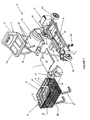
Figure 2 is an exploded perspective of the cart shown inFigure 1 . -
Figure 3 is a partial view of the cart inFigure 1 showing the steering unit. -
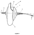
Figure 4 is a side view of the front wheel of the motorized cart inFigure 1 with the tire partially cutaway. -
Figure 5 is a schematic view of the hub gear motor system in the motorized cart ofFigure 1 . -
Figure 6A is a partial inside view of the front wheel and means for driving the cart ofFigure 1 with part of the casing and fourth gear removed. -
Figure 6B is a partial inside view of the part of the casing and fourth gear removed from the front wheel ofFigure 6A . -
Figure 7 is a schematic diagram of the hub gear motor system of the cart inFigure 1 . - Referring to the drawings in which like reference numerals designate like or corresponding parts throughout the several views, there is shown in
Figures 1 and7 , a motorized cart (1) with a hub gear motor system (2). The motorized cart (1) comprises a cart body (10). The hub gear motor system (2) includes means for driving the cart body, means for powering the driving means and means for controlling the driving means. - The cart body (10) includes a platform (11) with a seat (12), a plurality of wheels, a steering unit (13) and a storage receptacle (14). As shown in
Figure 2 , the cart body (10) also has a support frame (15) that provides an infrastructure for supporting the seat (12) and the platform (11). The support frame (15) itself is comprised of a plurality of longitudinal pieces and cross pieces. The support frame (15) also includes a column support bracket (17) which has an outer support surface (18) thereon. - Referring to
Figures 2 and3 , the steering unit (13) is shown to include a steering column (23) having two ends with a handle (24) at one of the ends. Disposed on the end of the steering column (23) opposite the handle (24) are a fork assembly (26), a pivot bearing (25) and a frame attaching plate (20). - The seat (12) is characterized by a bench (30) with a back support (31) and a plurality of seat legs (32) that mount the bench (30) and back support (31) on the support frame (15) of the cart body (10).
- In a preferred embodiment, the storage receptacle is a basket (14) having a plurality of walls. Basket support legs (37) mount the basket (14) above the support frame (15) of the motorized cart (1). The basket's walls include a bottom wall (36), a leading wall (38), a trailing wall (39) and a pair of side walls (40). The trailing wall (39) has an elongated opening (41) extending from its top edge to its bottom edge. An inlet (42) extends inwardly from the opening (41) at a top edge of the trailing wall (39). A slot (43) is formed at a bottom (36) of the opening in the bottom wall (36). The slot (43) is generally vertically aligned with the inlet (42).
- The cart body (10) also includes a covering assembly which comprises rear (46) and front (47) shrouds. The rear shroud 46) substantially covers the battery (21) and battery charger (22) It also houses a portion of the rear wheels (27). Toward the front of the cart (1), the front shroud (47) protects upper and side portions of the front wheel (28). Although in a preferred embodiment, it extends over the battery (21) and the battery charger (22), the rear shroud (46) could be removed or modified to provide additional storage space under the seat (12) were it desired.
- The plurality of wheels includes a pair of rear wheels (27) and a front wheel (28). Additionally, there are two anti-tip casters (29) on the cart body (10) located adjacent to the front wheel (28). The front wheel (28) as shown in
Figure 4 includes a rim (48) with a hub casing (49) and a tire (50). The tire (50) is mounted around the rim (48). Threaded rods (52) extend outwardly from the hub casing (49) on each side of the front wheel (28) defining a horizontal axis of the front wheel (28) which comprises a first rotational axis (A). - Referring to
Figures 2 and3 , the means for powering the driving means of the motorized cart include a battery (21) accompanied by a battery charger (22). The means for controlling the driving means comprise a control box (67) a power width modulator (PWM) controller (65), and a plurality of leads. Each of said leads preferably comprises a cable. - In
Figures 5 ,6A and 6B , the means for driving the cart is shown to comprise an electric reversible motor (66), first (54), second (55), third (56) and fourth (57) gears and an intermediate plate (69). The means for driving the cart is contained within the hub casing (49) of the cart's front wheel (28). The fourth gear (57) has a keyway (58) thereon. - Referring to
Figures 2 ,3 and7 , the plurality of leads includes motor leads (71), control leads (70), and power leads (73). The PWM controller (65) is connected to the electric reversible motor (66) by the motor leads (71). It is further connected to the control box (67) by the control leads (70). Power leads (73) extend between the PWM controller (65) and the battery charger (22), the battery (21) and the PWM controller (65), and the battery charger (22) and the battery (21). - In a preferred embodiment of
Figure 2 , the frame (15) has a generally rectangular shape with the platform (11) supported thereon. The platform (11) includes a generally planar surface that serves as a foot support area for passengers in the cart (1). - Regarding the steering unit (13) in
Figure 3 , the steering column (23) is an elongated bar having two ends with the fork assembly (26) disposed at one of the ends and the handle (24) disposed at the opposite end of the column (23). The fork assembly (26) is U-shaped and is formed by two arms (60) and a yoke (61). The two arms (60) are disposed parallel to each other with the yoke (61) adjoining the two arms (60). Therefore, one end of each arm (60) is attached to the yoke (61), while the opposite end is attached to a respective threaded rod (52) on the front wheel (28). Each arm (60) extends to an opposite side of the front wheel (28) so that the fork assembly (26) straddles the front wheel (28). One end of the pivot bearing (25) is adjacent to the yoke (61) and the opposite end receives the steering column (23). The frame attaching plate (20) is mounted to a side of the pivot bearing (25) such that the steering unit (13) can pivot independently of the cart's frame (15). - In a preferred embodiment of
Figure 1 , the basket (14) has a rectangular configuration. The basket support legs (37) are U-shaped comprising a pair of spaced-apart, generally parallel members and a connecting cross piece. The parallel members of each basket support leg (37) are respectively attached to the basket (14) and to the frame (15). The seat legs (32) support the horizontal bench (30) and back support (31) above the platform (11). The seat (12) is adapted to accommodate a passenger comfortably on the motorized cart (1). The handle (24) of the front steering unit (13) comprises a tubular member. However, the handle can be reconfigured to various other suitable shapes. - The rear shroud (46) protects the battery (21) and battery charger (22) and helps to secure them on the platform (11) of the cart (1). When covered, the battery (21) and battery charger (22) are less likely to come into direct contact with people or objects, thereby reducing the possibility of damage or injury. In addition, the rear shroud (46) deters vandalism to the battery (21) and battery charger (22).
- The front shroud (47) is on a front section of the support frame (15). It extends over a lower portion of the steering unit (13) and covers part of the front wheel (28) including the PWM controller (65). The front cover (47) acts as a protective mechanism to deter passengers and other objects from coming into contact and/or becoming entangled with the cart's front wheel (28). In addition, the rear (46) and front (47) shrouds enhance the aesthetic appeal of the cart (1). Preferably, the shrouds (46,47) are made of plastic, but fiberglass or other suitable lightweight materials could be used instead.
- The support frame (15) of the cart body (10) provides a base for supporting particular elements of the cart (1), including the seat (12), the platform (11), the basket (14) and the hub gear motor system (2).
- The basket (14) is a receptacle for storing items. It is especially useful for cart users when shopping. The slot (43) in the basket's bottom (36) in cooperation with the elongated opening (41) in the trailing wall (39) and the inlet (42) in the trailing wall (39) form a column receiver that partially encircles a portion of the steering column (23) of the steering unit (13). By manipulating the handles (24) on the steering unit (13) a passenger is able to steer the motorized cart (1) in the desired direction. As the handle (24) is moved by the user, the steering motion translates from the handle (24) through the steering column (23) to the front wheel (28) of the cart (1). The fork assembly (26) moves the front wheel (28) in direct response to the movement of the steering column (23).
- The hub gear motor system (2) moves the cart by rotating the front wheel (28) of the cart in selected forward and rearward motions. Within the hub casing (49) in
Figures 5 ,6A and 6B , the gears (54-57) of the means for driving the cart body link the electric reversible motor (66) to the front wheel (28) and translate the rotational motion of the electric reversible motor (66) to the front wheel (28). Rotation of the front wheel (28) provides movement to the motorized cart (1). - The means for driving the cart body is actuated by the means for powering. Specifically, the electrical reversible motor (66) is driven by the battery (21). The motor (66) is operated by the user via the control box (67). The speed and direction of the electric reversible motor (66) are modulated by the user via a throttle on the control box (67), while the voltage directed to the motor is regulated by the PWM controller.
- In a preferred embodiment, the throttle comprises a wig-wag switch (68). By manually manipulating the wig-wag switch (68), a user selects the desired speed and direction of the electric reversible motor (66). Although a wig-wag switch is preferred, other types of suitable switches could be used instead of a wig-wag switch to control the speed and direction of the cart.
- The electric reversible motor (66) rotates the front wheel (28). The front wheel (28) can move in both a forward direction and a reverse direction on the cart (1) in response to the rotation of the electric reversible motor (66). The first (54), second (55), third (56) and fourth (57) gears translate the rotational motion of the electric reversible motor (66) to the front wheel (28). Disposed in the fourth gear (57) of the motor (53), the keyway (58) enables the front wheel (28) to move in both forward and reverse directions as the motor (66) moves in corresponding forward and reverse directions.
- The column support bracket (17) on the front end of the frame (15) adjoins the attaching plate (20) on the pivot bearing (25) in order to mount the steering unit (13) onto the support frame (15) of the cart (1). Disposed on the column support bracket (17) is the outer support surface (18). This surface (18) is angled upwardly and supports the PWM controller (65) thereon.
- The front (28) and rear (27) wheels and the anti-tip casters (29) are mounted on the support frame (15) of the motorized cart (1). Each of the anti-tip casters (29) are positioned on a respective side of the front wheel (28) at the front end of the support frame (15). Flanking the front wheel (28), the anti-tip casters (29) are generally aligned with each other and are approximately aligned with the front wheel (28).
- The anti-tip casters (29) are a safety feature and function to deter sideways tipping of the motorized cart (1). If the motorized cart (1) tilts too far to one side, the anti-tip caster (29) on that side engages the floor to limit further tipping of the cart (1). As such, the casters (29) are positioned for intermittent contact with the supporting surface on which the cart (1) rests. Consequently, either one or none of the anti-tip casters (29) are contacting the floor or supporting surface at a given time.
- In the front wheel's hub casing (49), the first gear (54) is rigidly attached to the rotor (74), a rotating arm of the electric reversible motor (66). The first gear (54) rotates with the rotor (74) when the electric reversible motor (66) is operating. The teeth of the second gear (55) are engaged with the teeth of the first gear (54) as shown in
Figures 5 ,6A and 6B . The third gear (56) is fixed to the second gear (55) with the axes of the second (55) and third (56) gears being coincident along a second rotational axis (B). This second rotational axis (B) is offset from the first rotational axis (A). The teeth of the third gear (56) are in engagement with the fourth gear (57). The fourth gear (57) is rigidly attached to the hub casing (49) which is mounted to the front wheel (28) by screws or other suitable means. The second (55) and third (56) gears are rotatably mounted on opposite sides of the intermediate plate (69) which is rigidly attached at its perimeter to the rotor. While the second (55) and third (56) gears rotate together about the second rotational axis (B), the intermediate plate (69) rotates with the rotor (74) about the first rotational axis (A). - In a preferred embodiment, the motorized cart (1) has a top speed of approximately two miles per hour. The first gear (54) has 19 teeth and the second gear (55) includes 62 teeth. The third gear (56) is the smallest comprising 11 teeth, while the fourth gear (57) has 70 teeth. In this preferred embodiment, the gear ratio for the hub gear motor system (54) is about 21 to 1 with the diameter of the front wheel (28) being approximately 8 inches. The battery (21) is a 12-volt battery. This combination results in the preferred top speed of the cart (1) of two miles per hour.
- Particular motion components of the cart (1) can be varied to obtain different resultant top speeds, if desired. The motion components of the motorized cart (1) include the diameter of the front wheel, the voltage capacity of the battery power source, and the gear ratios between the cooperating gears. As for example, by increasing the diameter of the front wheel, the maximum speed of the motor can be increased. The top speed of the cart can also be increased by increasing the voltage of the battery. As is conventionally recognized, by decreasing the overall gear ratio of the hub gear motor system, the resultant top speed of the cart can be increased. Conversely, by increasing the overall gear ratio, the maximum speed of the cart can be decreased.
- To use the motorized cart, a passenger sits in the seat placing his/her feet on the foot support area of the platform (11). The passenger selects either the forward or the reverse direction from the control box (67) and activates the cart to move at a selected speed. As the cart moves, the user steers the front wheel (28) in the desired direction. To stop the cart (1) the switch (68) is released and the cart comes to a stop.
- During use, the electric reversible motor (66) directly rotates the first gear (54) in the direction selected on the control box (67). The rotation of the first gear (54) drives the second gear (55). As the second gear (55) rotates, the third gear (56) turns at the same rotational speed and imparts movement to the fourth gear (57). With the fourth gear (57) affixed to the front wheel's casing (49), the movement of the fourth gear (57) directly effects movement of the front wheel (28) and therefore movement of the cart (1).
- Once the cart (1) is in motion, the passenger can maneuver the cart (1) by turning the front wheel (28) via the steering unit (13) in the direction he or she desires to travel. The cart (1) can be activated to move in either the forward or reverse direction by selecting the rotational direction of the electric motor (66). The rotational direction of the electric reversible motor (66) is selected using the switch (68) on the control box (67).
- In one preferred embodiment a dynamic braking action which is effected by the PWM controller (65) stops the motorized cart (1). To stop the cart (1), the user releases the switch (68) which signals the PWM controller (65) via the control leads (70). Signaling through the power (73) and motor (71) leads, the PWM controller (65) drops the amount of voltage to the electric motor (66) and the cart (1) comes to a stop. Although the dynamic braking action implemented by the PWM controller (65) is disclosed herein, other suitable types of braking systems could be used to slow and/or stop the cart during use.
- The cart moves as the front wheel is activated by the electric motor (66). With front wheel drive, the rear wheels of the cart track with the movement of the front wheel and the motorized cart can be turned in an amount of space equal in length to the length of the cart. With a smaller turning radius, the motorized cart of the present invention can be easily maneuvered about in small areas.
- With the hub gear motor system of the motorized cart, the cart is pulled in a forward direction by the movement of the front wheel. Since the motorized cart has front wheel drive, skidding of the front wheel is minimized when cornering the cart.
- The storage receptacle is preferably, though not necessarily, supported directly on the frame of the cart rather than the steering column. Being attached to the frame, the weight of the basket and its contents do not interfere with steering the cart.
- The cart can be moved in both forward and reverse directions via the gears by changing the motion of the electric reversible motor which engages and rotates the front wheel. By reversing the direction of the motor, the front wheel can be rotated in an opposite direction. Furthermore, the hub gear motor system enables the motorized cart to operate effectively using a 12-volt battery.
- Although the present invention has been described in considerable detail with reference to certain preferred versions thereof, other versions are possible, as long as key lie within the scope of the appended claims.
Claims (19)
- A motorized cart (1) comprising: a cart body (10) and a hub gear motor system (2), said hub gear motor system (2) comprising means for driving the cart body (10), means for powering the driving means (21) and means for controlling the driving means (67), said cart body (10) including a plurality of wheels (27, 28) including at least one rear wheel (27) and at least one front wheel (28), said front wheel (28) comprising a rim (48) and a hub casing (49) attached to said rim (48), said means for driving the cart body (10) rotating the at least one front wheel (28) in forward and rearward directions to thereby move the motorized cart (1), said means for driving comprising: an electric reversible motor (66) with a rotor (74) and first, second, third and fourth gears (54-57), wherein the first gear (54) is attached to the rotor (74) on the electric reversible motor (66) and the fourth gear (57) is fixedly attached to the hub casing (49) of the front wheel (28), the first gear (54) engages the second gear (55), the fourth gear (57) engages the third gear (56), the first and fourth gears (54, 57) are rotatable about a first rotational axis, the second gear (55) is attached to the third gear (56) and said second and third gears (55, 56) rotate about a second rotational axis, the second rotational axis being offset from the first rotational axis, so that said first gear (54) is rotated by the electric reversible motor (66), the second gear (55) is driven by said first gear (54), the third gear (56) rotates with said second gear (55), said fourth gear (57) is driven by said third gear (56) and the front wheel (28) is driven by said fourth gear (57), wherein said electric reversible motor (66) and said first, second, third, and fourth gears (54-57) are substantially contained within said hub casing (49) and said rim (48) of the front wheel (28).
characterised in that
said means for driving further comprises an intermediate plate (69) attached to the rotor (74) and substantially contained within the hub casing (49), the second and third gears (55, 56) being rotatably mounted on the intermediate plate (69). - The motorized cart (1) of claim 1, wherein said means for powering the drive means comprises a 12-volt battery (21).
- The motorized cart (1) of claim 2, wherein said means for powering the drive means further comprises a battery charger (22) for recharging the 12-volt battery (21).
- The motorized cart (1) of claim 1, wherein said first and fourth gears are rotatable about a first rotational axis which is coincident with a rotational axis of the front wheel (28).
- The motorized cart (1) of claim 4, wherein the gear ratio of the means for driving the cart (1) is approximately 21 to 1.
- The motorized cart (1) of claim 5, wherein a diameter of the front wheel (28) is about 20,3 cm (8 inches).
- The motorized cart (1) of claim 4, wherein the first gear comprises 19 teeth, the second gear comprises 62 teeth, the third gear comprises 11 teeth and the fourth gear comprises 70 teeth.
- The motorized cart (1) of claim 1, wherein said hub gear motor system (2) further comprises a battery (21).
- The motorized cart (1) of claim 8, wherein said battery (21) is mounted on a rear section of the cart body (10).
- The motorized cart (1) of claim 8, wherein said hub gear motor system (2) further comprises: a control box; a power width modulator controller; and a plurality of leads adjoining the control box, the power width modulator controller, the battery (21) and the motor (66).
- The motorized cart (1) of claim 10, wherein said plurality of leads comprise: power leads connecting the battery (21) and battery charger (22) to the power width modulator controller ; control leads connecting the control box to the power width modulator controller; and motor (66) leads connecting the motor (66) to the power width modulator controller.
- The motorized cart (1) of claim 11, wherein each of said leads comprises a cable.
- A hub gear motor system (2) for use on a front wheel (28) of a motorised cart, said hub gear motor system (2) comprising a hub casing (49) adapted to attach to a rim (48) of the vehicle wheel (28), means for driving a cart body (10) of the motorised cart by rotating the front wheel (28) in forward and rearward directions to thereby move the motorized cart, said means for driving comprising: an electric reversible motor (66) with a rotor (74), and first, second, third and fourth gears (54-57), wherein the first gear (54) is attached to the rotor (74) on the electric reversible motor (66) and the fourth gear (57) is adapted for fixed attachment to the wheel (28), the first gear (54) engages the second gear (55), the fourth gear (57) engages the third gear (56), the first and fourth gears (54; 57) are rotatable about a first rotational axis, the second and third gears (55, 56) rotate about a second rotational axis, the second rotational axis being offset from the first rotational axis, so that said first gear (54) is rotated by the electric reversible motor (66), the second gear (55) is driven by said first gear (54), the third gear (56) rotates with said second gear (55), said fourth gear (57) is driven by said third gear (56) and said fourth gear (57) is adapted to drive the wheel (28), wherein said electric reversible motor (66) and said first, second, third and fourth gears (54-57) are substantially contained within the hub casing (49) and adapted to be substantially contained within the rim (48) of the wheel (28), said fourth gear (57) being fixedly attached to the hub casing (49),
characterised in that
said means for driving further comprises an intermediate plate (69) attached to the rotor (74) and substantially contained within the hub casing (49), the second and third gears (55, 56) being rotatably mounted on the intermediate plate (69). - The hub gear motor system (2) of claim 13, further comprising a 12-volt battery(21) to provide power to the electric reversible motor (66).
- The hub gear motor system (2) of claim 14, further comprising a battery charger (22) to recharge the 12-volt battery (21).
- The hub gear motor system (2) of claim 13, further comprising a control box, a power width modulator controller, and a plurality of leads; said plurality of leads includes power leads extending between the power width modulator controller and the battery (21), control leads extending between the control box and the power width modulator controller, and motor (66) leads extending between the motor (66) and the power width modulator controller.
- The hub gear motor system (2) of claim 16, wherein said control box includes a throttle for controlling the speed and direction of the electric reversible motor (66); and said power width modulator regulates the voltage applied to the motor (66) in response to the throttle.
- The hub gear motor system (2) of claim 17, wherein said battery charger (22) and said battery (21) are connected to a power width modulator controller by power leads, a control box is connected to said power width modulator controller by control leads, and said motor (66) is connected to said power width modulator controller by motor leads.
- A motorized cart (1) as claimed in Claim 1, wherein said cart body (10) includes a support frame, a steering unit, a seat and a platform; said plurality of wheels is attached to said support frame; a plurality of anti-tip casters generally aligned with said front wheel (28), wherein one of said anti-tip casters is positioned on one side of said front wheel (28) and another of said anti-tip casters is positioned on another side of said front wheel (28); said front wheel (28) comprises a tire and two threaded rods, said hub casing (49) is mounted to opposite sides of the rim (48) and said threaded rods define a horizontal rotational axis of the front wheel (28) comprising a first rotational axis; said steering unit comprises a steering column; said hub gear motor system (2) a 12-volt battery (21) and a battery charger (22), wherein said battery (21) provides power to the electric reversible motor (66); a control box, a power width modulator controller and a plurality of leads; wherein said control box is mounted on the steering unit and controls the speed and direction of the electric reversible motor (66);
said power width modulator controller regulates voltage directed to the motor (66) via the throttle; said plurality of leads comprises power leads, control leads and motor leads, wherein said power leads extend between the battery (21), the battery charger (22) and the power width modulator; said control leads extend between said control box and said power width modulator; and said motor leads extend between said electric reversible motor (66) and said power width modulator.
Applications Claiming Priority (3)
| Application Number | Priority Date | Filing Date | Title |
|---|---|---|---|
| US34805101P | 2001-11-06 | 2001-11-06 | |
| US348054P | 2001-11-06 | ||
| PCT/US2002/037278 WO2003039937A2 (en) | 2001-11-06 | 2002-11-05 | Motorized cart with hub gear motor system |
Publications (3)
| Publication Number | Publication Date |
|---|---|
| EP1453715A2 EP1453715A2 (en) | 2004-09-08 |
| EP1453715A4 EP1453715A4 (en) | 2011-04-13 |
| EP1453715B1 true EP1453715B1 (en) | 2013-07-24 |
Family
ID=32926126
Family Applications (1)
| Application Number | Title | Priority Date | Filing Date |
|---|---|---|---|
| EP02789784.2A Expired - Lifetime EP1453715B1 (en) | 2001-11-06 | 2002-11-05 | Motorized cart with hub gear motor system |
Country Status (6)
| Country | Link |
|---|---|
| US (1) | US7108090B2 (en) |
| EP (1) | EP1453715B1 (en) |
| AU (1) | AU2002352828A1 (en) |
| CA (1) | CA2465674C (en) |
| MX (1) | MXPA04004163A (en) |
| WO (1) | WO2003039937A2 (en) |
Families Citing this family (33)
| Publication number | Priority date | Publication date | Assignee | Title |
|---|---|---|---|---|
| WO2005110791A2 (en) | 2004-05-07 | 2005-11-24 | Wilson Charles E | Electric golf cart and utility cart |
| US8925659B2 (en) * | 2004-05-07 | 2015-01-06 | Charles E. Wilson | Electric utility vehicle |
| US7328761B1 (en) * | 2004-08-18 | 2008-02-12 | Tyler James H | Steerable trailer drive assembly |
| WO2006102183A2 (en) | 2005-03-18 | 2006-09-28 | Gatekeeper Systems, Inc. | Two-way communication system for tracking locations and statuses of wheeled vehicles |
| CA2620062C (en) | 2005-08-25 | 2015-10-27 | Gatekeeper Systems, Inc. | Systems and methods for locating and controlling powered vehicles |
| US20070045014A1 (en) * | 2005-08-29 | 2007-03-01 | Greig Mark E | Maneuverable motorized personally operated vehicle |
| GB2440322B (en) * | 2006-07-25 | 2011-07-06 | Advanced Vehicle Concepts Ltd | Wheeled vehicle |
| US8042869B2 (en) | 2007-07-13 | 2011-10-25 | Kids Ii, Inc. | Child seat liner |
| US7823675B2 (en) | 2008-07-18 | 2010-11-02 | Ali Kermani | Drifting kart |
| US8585062B2 (en) * | 2009-11-09 | 2013-11-19 | Nucleus Scientific, Inc. | Tunable pneumatic suspension |
| US8519575B2 (en) | 2009-11-09 | 2013-08-27 | Nucleus Scientific, Inc. | Linear electric machine with linear-to-rotary converter |
| US8624699B2 (en) | 2009-11-09 | 2014-01-07 | Nucleus Scientific, Inc. | Electric coil and method of manufacture |
| US8362660B2 (en) * | 2009-11-09 | 2013-01-29 | Nucleus Scientific, Inc. | Electric generator |
| US8167061B2 (en) * | 2010-01-11 | 2012-05-01 | GM Global Technology Operations LLC | Electric powered cart for moving loads |
| US20120012409A1 (en) * | 2010-07-16 | 2012-01-19 | Patrick Edward Turner | Power-Assist Hand Truck or Platform Cart |
| US8766493B2 (en) | 2011-07-01 | 2014-07-01 | Nucleus Scientific, Inc. | Magnetic stator assembly |
| US8991529B2 (en) * | 2013-01-21 | 2015-03-31 | GM Global Technology Operations LLC | Self-motivated cargo pod |
| USD793912S1 (en) | 2014-05-09 | 2017-08-08 | Razor Usa Llc | Drifting kart |
| US20150328994A1 (en) | 2014-05-13 | 2015-11-19 | Razor Usa Llc | Kart |
| USD771196S1 (en) | 2014-06-03 | 2016-11-08 | Razor Usa Llc | Drifting kart |
| USD774981S1 (en) | 2015-03-19 | 2016-12-27 | Razor Usa Llc | Drifting kart |
| US9669857B1 (en) | 2015-07-01 | 2017-06-06 | Randall D Rainey | Propulsion device for hand-pushed equipment |
| USD793481S1 (en) | 2016-05-17 | 2017-08-01 | Razor Usa Llc | Drifting kart |
| CN206012763U (en) | 2016-08-15 | 2017-03-15 | 美国锐哲有限公司 | A kind of kart |
| US10476360B2 (en) | 2016-09-13 | 2019-11-12 | Indigo Technologies, Inc. | Axial flux motor having rotatably coupled coil stator assemblies and methods of using same |
| US10351201B1 (en) * | 2016-11-01 | 2019-07-16 | Chester Wright | Personal mobility shopping cart |
| US11225167B2 (en) * | 2018-10-02 | 2022-01-18 | Assembled Products Corporation | Electric cart |
| US11767060B2 (en) * | 2019-04-12 | 2023-09-26 | Textron Innovations Inc. | Lightweight vehicle |
| CN110478140A (en) * | 2019-08-20 | 2019-11-22 | 郴州市第一人民医院 | A multifunctional variable speed electric first aid cart in the field |
| US11117603B1 (en) * | 2019-11-05 | 2021-09-14 | Shelia Hunter | Motorized medicine cart |
| JP7654361B2 (en) * | 2020-07-02 | 2025-04-01 | 株式会社エクセディ | Drive unit |
| USD1078549S1 (en) | 2023-08-14 | 2025-06-10 | Razor Usa Llc | Cart |
| ES1322932Y (en) * | 2024-09-26 | 2026-01-19 | Turon Mobility S L | COMPACT VEHICLE |
Family Cites Families (26)
| Publication number | Priority date | Publication date | Assignee | Title |
|---|---|---|---|---|
| US626713A (en) * | 1899-06-13 | Self-regulating dynamo | ||
| US672713A (en) | 1900-12-03 | 1901-04-23 | Enrique Sanchis | Horseless carriage. |
| US3090456A (en) * | 1961-04-04 | 1963-05-21 | Fairchild Stratos Corp | Electrically powered wheel |
| US3897843A (en) * | 1973-11-29 | 1975-08-05 | Gen Electric | Electric motorized wheel |
| US3872945A (en) * | 1974-02-11 | 1975-03-25 | Falcon Research And Dev Co | Motorized walker |
| US3948332A (en) * | 1975-01-22 | 1976-04-06 | Tyner Richard A | Electric caddy cart |
| CA1115642A (en) * | 1980-11-06 | 1982-01-05 | H. Michael Doman | Motorized vehicle |
| US4403673A (en) * | 1981-01-06 | 1983-09-13 | Douglas Ball | Powered vehicle |
| US4412595A (en) * | 1981-04-10 | 1983-11-01 | Kinzel Augustus B | Three wheeled vehicle |
| DE3917831C1 (en) * | 1989-06-01 | 1990-07-26 | Carl Hurth Maschinen- Und Zahnradfabrik Gmbh & Co, 8000 Muenchen, De | |
| IL98376A0 (en) * | 1991-06-04 | 1992-07-15 | Afikim S A E | Vehicle |
| IT1251294B (en) * | 1991-08-23 | 1995-05-08 | Giampietro Canderle | ELECTRICALLY MOTORIZED WHEEL, ESPECIALLY FOR BICYCLES, WITH BUILT-IN MECHANICAL GEARBOX |
| US5366037A (en) * | 1992-11-23 | 1994-11-22 | Invacare Corporation | Powered wheelchair having drive motors integrated into driven wheels |
| US5366036A (en) * | 1993-01-21 | 1994-11-22 | Perry Dale E | Power stand-up and reclining wheelchair |
| US5375673A (en) * | 1993-04-02 | 1994-12-27 | Mccall; Amiel J. | Golf bag card accessory drive unit |
| US5691584A (en) * | 1993-09-09 | 1997-11-25 | Honda Giken Kogyo Kabushiki Kaisha | Wheel motor for vehicles |
| JP3369673B2 (en) * | 1993-09-28 | 2003-01-20 | 本田技研工業株式会社 | Wheel motor |
| DE4411208A1 (en) * | 1994-03-31 | 1995-10-05 | Zeiss Carl Fa | Coarse and fine drive for a lens |
| US5521808A (en) * | 1994-05-06 | 1996-05-28 | Alcatel Network Systems, Inc. | Method and circuitry for controlling start-up characteristics of a magnetic amplifier control circuit |
| US5600191A (en) * | 1994-12-19 | 1997-02-04 | Yang; Chen-Chi | Driving assembly for motor wheels |
| AU4620096A (en) * | 1995-01-23 | 1996-08-14 | Egon Schmid | Propulsion unit for an electrically operated vehicle |
| JP3552128B2 (en) * | 1995-05-17 | 2004-08-11 | 本田技研工業株式会社 | Battery mounting structure for electric vehicles |
| US5526894A (en) * | 1995-04-13 | 1996-06-18 | Wang; Eric J. F. | Power- and/or manually-driven collapsible golf cart |
| US6080077A (en) * | 1999-02-15 | 2000-06-27 | Igor Kamlukin | Planetary gear drive train |
| US6321863B1 (en) * | 2000-06-26 | 2001-11-27 | Mac Brushless Motor Company | Hub motor for a wheeled vehicle |
| US6481518B1 (en) * | 2001-08-07 | 2002-11-19 | David Wu | Motor drive mounting arrangement for golf cart |
-
2002
- 2002-11-05 AU AU2002352828A patent/AU2002352828A1/en not_active Abandoned
- 2002-11-05 CA CA2465674A patent/CA2465674C/en not_active Expired - Lifetime
- 2002-11-05 MX MXPA04004163A patent/MXPA04004163A/en active IP Right Grant
- 2002-11-05 US US10/288,805 patent/US7108090B2/en not_active Expired - Lifetime
- 2002-11-05 WO PCT/US2002/037278 patent/WO2003039937A2/en not_active Ceased
- 2002-11-05 EP EP02789784.2A patent/EP1453715B1/en not_active Expired - Lifetime
Also Published As
| Publication number | Publication date |
|---|---|
| AU2002352828A1 (en) | 2003-05-19 |
| US7108090B2 (en) | 2006-09-19 |
| AU2002352828A8 (en) | 2005-10-27 |
| WO2003039937A2 (en) | 2003-05-15 |
| MXPA04004163A (en) | 2005-01-25 |
| CA2465674A1 (en) | 2003-05-15 |
| US20030085064A1 (en) | 2003-05-08 |
| EP1453715A2 (en) | 2004-09-08 |
| WO2003039937A8 (en) | 2004-09-10 |
| WO2003039937A3 (en) | 2004-02-26 |
| CA2465674C (en) | 2011-02-08 |
| EP1453715A4 (en) | 2011-04-13 |
Similar Documents
| Publication | Publication Date | Title |
|---|---|---|
| US7108090B2 (en) | Motorized cart with hub gear motor system | |
| US4094374A (en) | Two wheeled electrically powered vehicle | |
| US3524512A (en) | Self-propelled driving and steering truck for shopping carts | |
| US6907949B1 (en) | Battery powered motor vehicle and method of use | |
| US4562893A (en) | Toy vehicle | |
| JP2688008B2 (en) | Lawn mower | |
| US7086491B2 (en) | Personal compact cart | |
| US20080041644A1 (en) | Electric shopping cart/burden carrier | |
| US3934669A (en) | Powered vehicle | |
| US5375673A (en) | Golf bag card accessory drive unit | |
| US4846295A (en) | Steerable motorized three-wheeled vehicles for use by the handicapped and others desiring assistance | |
| US4020916A (en) | Self-propelled shopping cart | |
| CA2447019A1 (en) | Motorized towing apparatus | |
| US10130531B1 (en) | Apparatus for constructing variable configurations of an attachable/detachable motorized drive for standard wheelchairs | |
| JPH10230879A (en) | Motor-driven vehicle | |
| JP2009083774A (en) | Electric walking cart | |
| US8113305B1 (en) | Powered patient transport vehicle | |
| WO2022043482A1 (en) | Collapsible shopping trolley with auxiliary electric motor | |
| US20020088657A1 (en) | Method and apparatus for motorizing a wheelchair | |
| US20030094315A1 (en) | Solar powered transporter | |
| US20050230928A1 (en) | Power assisted hand truck | |
| KR20120096118A (en) | Passivity and electro motion wheelchairs | |
| KR20160073269A (en) | Electric vehicle capable of carrying the rear wheel of un-powered transportation apparatus | |
| NL1001294C2 (en) | Mobile lifting device. | |
| GB2244684A (en) | Electric four wheel drive wheelchair |
Legal Events
| Date | Code | Title | Description |
|---|---|---|---|
| PUAI | Public reference made under article 153(3) epc to a published international application that has entered the european phase |
Free format text: ORIGINAL CODE: 0009012 |
|
| 17P | Request for examination filed |
Effective date: 20040428 |
|
| AK | Designated contracting states |
Kind code of ref document: A2 Designated state(s): AT BE BG CH CY CZ DE DK EE ES FI FR GB GR IE IT LI LU MC NL PT SE SK TR |
|
| AX | Request for extension of the european patent |
Extension state: AL LT LV MK RO SI |
|
| A4 | Supplementary search report drawn up and despatched |
Effective date: 20110311 |
|
| 17Q | First examination report despatched |
Effective date: 20110801 |
|
| REG | Reference to a national code |
Ref country code: DE Ref legal event code: R079 Ref document number: 60245292 Country of ref document: DE Free format text: PREVIOUS MAIN CLASS: B62D0001000000 Ipc: B60K0007000000 |
|
| GRAP | Despatch of communication of intention to grant a patent |
Free format text: ORIGINAL CODE: EPIDOSNIGR1 |
|
| RIC1 | Information provided on ipc code assigned before grant |
Ipc: B60K 7/00 20060101AFI20130109BHEP Ipc: B62B 5/00 20060101ALI20130109BHEP Ipc: B62K 5/025 20130101ALI20130109BHEP |
|
| GRAS | Grant fee paid |
Free format text: ORIGINAL CODE: EPIDOSNIGR3 |
|
| GRAA | (expected) grant |
Free format text: ORIGINAL CODE: 0009210 |
|
| AK | Designated contracting states |
Kind code of ref document: B1 Designated state(s): AT BE BG CH CY CZ DE DK EE ES FI FR GB GR IE IT LI LU MC NL PT SE SK TR |
|
| REG | Reference to a national code |
Ref country code: GB Ref legal event code: FG4D |
|
| REG | Reference to a national code |
Ref country code: CH Ref legal event code: EP |
|
| REG | Reference to a national code |
Ref country code: AT Ref legal event code: REF Ref document number: 623196 Country of ref document: AT Kind code of ref document: T Effective date: 20130815 |
|
| REG | Reference to a national code |
Ref country code: IE Ref legal event code: FG4D |
|
| REG | Reference to a national code |
Ref country code: DE Ref legal event code: R096 Ref document number: 60245292 Country of ref document: DE Effective date: 20130919 |
|
| REG | Reference to a national code |
Ref country code: AT Ref legal event code: MK05 Ref document number: 623196 Country of ref document: AT Kind code of ref document: T Effective date: 20130724 |
|
| REG | Reference to a national code |
Ref country code: NL Ref legal event code: VDEP Effective date: 20130724 |
|
| PG25 | Lapsed in a contracting state [announced via postgrant information from national office to epo] |
Ref country code: CY Free format text: LAPSE BECAUSE OF FAILURE TO SUBMIT A TRANSLATION OF THE DESCRIPTION OR TO PAY THE FEE WITHIN THE PRESCRIBED TIME-LIMIT Effective date: 20130703 Ref country code: PT Free format text: LAPSE BECAUSE OF FAILURE TO SUBMIT A TRANSLATION OF THE DESCRIPTION OR TO PAY THE FEE WITHIN THE PRESCRIBED TIME-LIMIT Effective date: 20131125 Ref country code: AT Free format text: LAPSE BECAUSE OF FAILURE TO SUBMIT A TRANSLATION OF THE DESCRIPTION OR TO PAY THE FEE WITHIN THE PRESCRIBED TIME-LIMIT Effective date: 20130724 Ref country code: BE Free format text: LAPSE BECAUSE OF FAILURE TO SUBMIT A TRANSLATION OF THE DESCRIPTION OR TO PAY THE FEE WITHIN THE PRESCRIBED TIME-LIMIT Effective date: 20130724 Ref country code: SE Free format text: LAPSE BECAUSE OF FAILURE TO SUBMIT A TRANSLATION OF THE DESCRIPTION OR TO PAY THE FEE WITHIN THE PRESCRIBED TIME-LIMIT Effective date: 20130724 |
|
| PG25 | Lapsed in a contracting state [announced via postgrant information from national office to epo] |
Ref country code: NL Free format text: LAPSE BECAUSE OF FAILURE TO SUBMIT A TRANSLATION OF THE DESCRIPTION OR TO PAY THE FEE WITHIN THE PRESCRIBED TIME-LIMIT Effective date: 20130724 Ref country code: ES Free format text: LAPSE BECAUSE OF FAILURE TO SUBMIT A TRANSLATION OF THE DESCRIPTION OR TO PAY THE FEE WITHIN THE PRESCRIBED TIME-LIMIT Effective date: 20130724 Ref country code: GR Free format text: LAPSE BECAUSE OF FAILURE TO SUBMIT A TRANSLATION OF THE DESCRIPTION OR TO PAY THE FEE WITHIN THE PRESCRIBED TIME-LIMIT Effective date: 20131025 Ref country code: FI Free format text: LAPSE BECAUSE OF FAILURE TO SUBMIT A TRANSLATION OF THE DESCRIPTION OR TO PAY THE FEE WITHIN THE PRESCRIBED TIME-LIMIT Effective date: 20130724 |
|
| PG25 | Lapsed in a contracting state [announced via postgrant information from national office to epo] |
Ref country code: CY Free format text: LAPSE BECAUSE OF FAILURE TO SUBMIT A TRANSLATION OF THE DESCRIPTION OR TO PAY THE FEE WITHIN THE PRESCRIBED TIME-LIMIT Effective date: 20130724 |
|
| PG25 | Lapsed in a contracting state [announced via postgrant information from national office to epo] |
Ref country code: SK Free format text: LAPSE BECAUSE OF FAILURE TO SUBMIT A TRANSLATION OF THE DESCRIPTION OR TO PAY THE FEE WITHIN THE PRESCRIBED TIME-LIMIT Effective date: 20130724 Ref country code: DK Free format text: LAPSE BECAUSE OF FAILURE TO SUBMIT A TRANSLATION OF THE DESCRIPTION OR TO PAY THE FEE WITHIN THE PRESCRIBED TIME-LIMIT Effective date: 20130724 Ref country code: CZ Free format text: LAPSE BECAUSE OF FAILURE TO SUBMIT A TRANSLATION OF THE DESCRIPTION OR TO PAY THE FEE WITHIN THE PRESCRIBED TIME-LIMIT Effective date: 20130724 Ref country code: EE Free format text: LAPSE BECAUSE OF FAILURE TO SUBMIT A TRANSLATION OF THE DESCRIPTION OR TO PAY THE FEE WITHIN THE PRESCRIBED TIME-LIMIT Effective date: 20130724 |
|
| PG25 | Lapsed in a contracting state [announced via postgrant information from national office to epo] |
Ref country code: IT Free format text: LAPSE BECAUSE OF FAILURE TO SUBMIT A TRANSLATION OF THE DESCRIPTION OR TO PAY THE FEE WITHIN THE PRESCRIBED TIME-LIMIT Effective date: 20130724 |
|
| PLBE | No opposition filed within time limit |
Free format text: ORIGINAL CODE: 0009261 |
|
| STAA | Information on the status of an ep patent application or granted ep patent |
Free format text: STATUS: NO OPPOSITION FILED WITHIN TIME LIMIT |
|
| REG | Reference to a national code |
Ref country code: CH Ref legal event code: PL |
|
| 26N | No opposition filed |
Effective date: 20140425 |
|
| PG25 | Lapsed in a contracting state [announced via postgrant information from national office to epo] |
Ref country code: LI Free format text: LAPSE BECAUSE OF NON-PAYMENT OF DUE FEES Effective date: 20131130 Ref country code: MC Free format text: LAPSE BECAUSE OF FAILURE TO SUBMIT A TRANSLATION OF THE DESCRIPTION OR TO PAY THE FEE WITHIN THE PRESCRIBED TIME-LIMIT Effective date: 20130724 Ref country code: CH Free format text: LAPSE BECAUSE OF NON-PAYMENT OF DUE FEES Effective date: 20131130 |
|
| REG | Reference to a national code |
Ref country code: DE Ref legal event code: R097 Ref document number: 60245292 Country of ref document: DE Effective date: 20140425 |
|
| REG | Reference to a national code |
Ref country code: IE Ref legal event code: MM4A |
|
| REG | Reference to a national code |
Ref country code: DE Ref legal event code: R119 Ref document number: 60245292 Country of ref document: DE Effective date: 20140603 |
|
| PG25 | Lapsed in a contracting state [announced via postgrant information from national office to epo] |
Ref country code: DE Free format text: LAPSE BECAUSE OF NON-PAYMENT OF DUE FEES Effective date: 20140603 |
|
| PG25 | Lapsed in a contracting state [announced via postgrant information from national office to epo] |
Ref country code: IE Free format text: LAPSE BECAUSE OF NON-PAYMENT OF DUE FEES Effective date: 20131105 |
|
| PG25 | Lapsed in a contracting state [announced via postgrant information from national office to epo] |
Ref country code: TR Free format text: LAPSE BECAUSE OF FAILURE TO SUBMIT A TRANSLATION OF THE DESCRIPTION OR TO PAY THE FEE WITHIN THE PRESCRIBED TIME-LIMIT Effective date: 20130724 |
|
| PG25 | Lapsed in a contracting state [announced via postgrant information from national office to epo] |
Ref country code: LU Free format text: LAPSE BECAUSE OF NON-PAYMENT OF DUE FEES Effective date: 20131105 Ref country code: BG Free format text: LAPSE BECAUSE OF FAILURE TO SUBMIT A TRANSLATION OF THE DESCRIPTION OR TO PAY THE FEE WITHIN THE PRESCRIBED TIME-LIMIT Effective date: 20130724 |
|
| REG | Reference to a national code |
Ref country code: FR Ref legal event code: PLFP Year of fee payment: 14 |
|
| REG | Reference to a national code |
Ref country code: FR Ref legal event code: PLFP Year of fee payment: 15 |
|
| REG | Reference to a national code |
Ref country code: FR Ref legal event code: PLFP Year of fee payment: 16 |
|
| PGFP | Annual fee paid to national office [announced via postgrant information from national office to epo] |
Ref country code: FR Payment date: 20211118 Year of fee payment: 20 Ref country code: GB Payment date: 20211118 Year of fee payment: 20 |
|
| REG | Reference to a national code |
Ref country code: GB Ref legal event code: PE20 Expiry date: 20221104 |
|
| PG25 | Lapsed in a contracting state [announced via postgrant information from national office to epo] |
Ref country code: GB Free format text: LAPSE BECAUSE OF EXPIRATION OF PROTECTION Effective date: 20221104 |