EP1453217A1 - Procédé d'atténuation de l'influence d'interférences produites par des systèmes de transmission radio en rafales sur des communications UWB - Google Patents
Procédé d'atténuation de l'influence d'interférences produites par des systèmes de transmission radio en rafales sur des communications UWB Download PDFInfo
- Publication number
- EP1453217A1 EP1453217A1 EP04290521A EP04290521A EP1453217A1 EP 1453217 A1 EP1453217 A1 EP 1453217A1 EP 04290521 A EP04290521 A EP 04290521A EP 04290521 A EP04290521 A EP 04290521A EP 1453217 A1 EP1453217 A1 EP 1453217A1
- Authority
- EP
- European Patent Office
- Prior art keywords
- signal
- receiver
- transmitter
- received
- threshold value
- Prior art date
- Legal status (The legal status is an assumption and is not a legal conclusion. Google has not performed a legal analysis and makes no representation as to the accuracy of the status listed.)
- Granted
Links
Images

Classifications
-
- H—ELECTRICITY
- H04—ELECTRIC COMMUNICATION TECHNIQUE
- H04B—TRANSMISSION
- H04B1/00—Details of transmission systems, not covered by a single one of groups H04B3/00 - H04B13/00; Details of transmission systems not characterised by the medium used for transmission
- H04B1/69—Spread spectrum techniques
- H04B1/7163—Spread spectrum techniques using impulse radio
- H04B1/719—Interference-related aspects
-
- H—ELECTRICITY
- H04—ELECTRIC COMMUNICATION TECHNIQUE
- H04B—TRANSMISSION
- H04B1/00—Details of transmission systems, not covered by a single one of groups H04B3/00 - H04B13/00; Details of transmission systems not characterised by the medium used for transmission
- H04B1/69—Spread spectrum techniques
- H04B1/7163—Spread spectrum techniques using impulse radio
- H04B1/71637—Receiver aspects
Definitions
- the present invention relates to a method for reducing the influence parasitic interference, due to existing wireless communication systems, in an ultra-wideband communication system (UWB communications which is an acronym for Ultra Wide Band).
- UWB communications which is an acronym for Ultra Wide Band.
- the invention aims to reduce, or even avoid any collision, with a neighboring bursty wireless transmission system, which can hinder good reception of an ultra-wide band signal intended for communication, in particular, over short distances, binary information whose bit rate is relatively low, around 10 kbits / s for example (PAN type communications for Personal Area Network).
- pulses of short duration and wide band of frequencies also called “wavelets”, these containing information for example in the form of position modulation relative wavelets over time (PPM type modulation).
- PPM type modulation position modulation relative wavelets over time
- the width of signal band generated can go up to 30% of the center frequency.
- this center frequency can be in a range from 1 to 5 GHz, for example.
- ultra-wide frequency band communication techniques have the advantage, for a given communication link, of allowing distribution of the power transmitted over a very wide frequency band, making them therefore bothersome vis-à-vis other narrowband communication links, they nevertheless suffer interference from existing radio links which are felt at the level of the receiver as so many parasites affecting good transmission of useful messages.
- the invention aims to provide a method for reducing as much as possible the influence of interference, due to existing radio communications, on UWB transmissions.
- the subject of the invention is therefore a method for attenuating the influence interference produced by burst radio transmission systems on UWB communications during which useful information is transmitted by a signal from a transmitter including a UWB signal modulator and an antenna transmission, to a receiver, the latter comprising a reception antenna and detection and demodulation means for discriminating said useful information in the signal received on said reception antenna, remarkable in that it consists, in said receiver, comparing the signal received on said receiving antenna with a first power threshold value and to prohibit the transmission of the received signal to said detection / demodulation means, if the power level of said signal received exceeds said first threshold value.
- the communication between the transmitter and the receiver is inoperative when interference has a level such as information useful cannot be faithfully received.
- FIG 1 there is shown a transmitter 1 and a receiver 2 between which communication can be established over a certain distance using signals UWB.
- an interesting application of the invention lies in the field of what is known as that of PAN networks. This may include, for example, monitoring the health status of people suffering from ailments where it is very important to know at all times certain physiological data. This can be the case for example for people suffering from a heart condition, an essential fact being in this case the heart rate.
- the physiological data being detected can be transmitted to a nearby relay station (at a distance of for example a few meters) with a reduced bit rate, for example by around 5 to 10 kbits / sec only.
- the transmitter 1 can be associated with or be part of equipment 3 for detecting a characteristic physical appearance of a person, a characteristic which is important for surveillance medical of it.
- it is a piece of equipment intended to detect the heart rate, located for this purpose on the body of a patient at monitor, in a place where blood circulation can easily be examined.
- all transmitter 1 and equipment 3 can be installed on the ear of the patient to detect blood circulation in situ.
- Receiver 2 can be located in a wristwatch serving as a relay and worn by the person. Through this relay, the information collected can be transferred further, for example to a central medical surveillance possibly via a telephone or a network long distance, such as the Internet.
- the receiver 2 can be incorporated directly in a telephone set then serving as a relay.
- the relay is symbolized by the rectangle R in figure 1.
- the equipment 3 generates a train of pulses Tx in which the useful information (in this case the heart rate) can be contained in the form of a PPM modulation, well known to specialists.
- This train of pulses is applied to transmitter 1 which has a UWB modulator 4 connected for this purpose to the equipment 3, the modulated signal being applied to a filtering circuit and 5 sending a useful signal s (t) UWB modulated in PPM depending on the Tx signal, on an antenna 6.
- the signal s (t) transmitted by the antenna 6 is received on an antenna 7 of the receiver 2 affected by certain disturbances such as noise, fading or interference due to other communications implemented nearby.
- the antenna 7 is connected to a filter 8 which transmits the received and filtered signal to a processing block 9 intended to reduce or even eliminate the influence of interference affecting the signal r (t).
- the signal After processing, the signal is applied to a UWB 10 detector and from there to a UWB 11 demodulator which, at its output, produces Rx data whose content is representative of that of the signal Tx previously sent to the modulator UWB 4 of the transmitter 1. These Rx data appear on an output terminal 12.
- the processing block 9 includes means symbolized by a block 13 called “protection” against interference and means symbolized by block 14 said “detection” intended to ensure detection of interference, then to analyze its content.
- the detection block 14 is arranged to fix two threshold values of power called respectively P and T with P >> T.
- the threshold value P is applied to the protection block 13. This is arranged to compare the power of the filtered signal appearing on the filter output 8 at threshold P. If the signal level is greater than or equal to this threshold, the block of protection 13 controls a blocking function symbolized by switch 15 on FIG. 1, by inhibiting any transmission of the signal to the detector 10. In this case, interference is so powerful that no proper signal reception useful is not possible and the operation of receiver 2 should therefore be prevented.
- a warning signal can be generated by protection block 13 and transmitted to demodulator 11, so that reception of the high level of interference can be signaled on output 12 and from there to relay R. Otherwise, the function of blocking is lifted (switch 15 closed) and the filtered signal is applied to the detector 10 and also to the detection block 14.
- the switch 15 is closed.
- the signal strength level r (t) filtered is then compared to the second threshold value T. If the signal strength filtered is greater than or equal to this threshold value T, we consider that the information useful cannot be correctly detected in the filtered signal. In this case, the detection block 14 sends, via a line 16, a rejection signal to the demodulator 11, which is therefore blocked. In these conditions again, no signal useful is only provided on output 12.
- the transmitter 1 also includes a reception circuit 18 which is connected to a clock circuit 19 determining the time relationship of useful pulses of the signal Tx supplied by the equipment 3.
- the receiver 2 for its part, further comprises a transmission circuit 20 capable of sending a clock adjustment signal SAH to the antenna 7 in the form of a signal containing clock adjustment information.
- This signal can be transmitted to the transmitter 1, where it is received by the reception circuit 18.
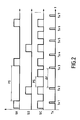
- the block of detection 14 is arranged in such a way that it is able to analyze the interference components contained in the signal received on the antenna 7 and discriminate in each of them the periods of silence PS (see also Figure 2) among periods of activity.
- the detection block 14 can draw from this information of discrimination the periods of silence PS during which the components due to interference sources are not present in the signal r (t) received on the antenna 7.
- the detection block 14 also includes a signal generator 21 adjustment SAH which is modulated on a carrier by the transmission circuit 20 and sent to the reception circuit 18 via the antennas 7 and 6.
- the signal adjustment SAH is representative of a time interval ⁇ t by which the signal useful Tx from equipment 3 will be delayed so that in the received signal r (t) the information to be detected and sent to output 12 no longer coincides with all the impulses due to interference.
- the detection block 14 As soon as the detection block 14 has determined the periods of silence PS in all interference emissions, it sends the SAH adjustment signal to the transmitter 1 and at the same time unlocks the demodulator 11 by activating line 17. The following useful pulses Tx3, Tx4, Tx5 . « can then be accepted and are transmitted on output 12. If the length of the period of silence PS changes, the block of detection 14 varies the interval ⁇ t accordingly so that the useful pulses Tx is always emitted during a period of silence PS, as long as the power of the interference received is between the threshold values P and T.
- the detection block 14 sends, via line 17, a signal to enable the demodulator 11, so that the signal detected by the detector 10 is directly processed by the demodulator 11 and a useful signal Rx can be presented on exit 12 provided of course, that at the instant considered, a transmission of a signal s (t) at transmitter 1 takes place.
- the value of the power threshold T must be set according to the characteristics of the sources of interference likely to emit in the space where transmitter 1 and receiver 2 will be used and also the noise level at which we risk to expect in this space. This value is therefore preferably either adjustable from outside the receiver, or fixed by the receiver itself. The receiver can set this value by allowing detector 14 to "listen" for its radio environment for a while. This automatic detection of values Reference thresholds can be repeated as desired at suitable intervals. In all In any case, the threshold value must be low enough to avoid errors of detection due to interference sources and, at the same time, sufficiently high to avoid false alarms.
- all the operating states such as the crossing of the threshold values P and T and the time offset using the signal SAH, can be signaled to relay R via a function of signaling implemented in the detection block 14, the corresponding signals being applied to relay R via a line 22.
Landscapes
- Engineering & Computer Science (AREA)
- Computer Networks & Wireless Communication (AREA)
- Signal Processing (AREA)
- Mobile Radio Communication Systems (AREA)
- Time-Division Multiplex Systems (AREA)
- Noise Elimination (AREA)
- Radio Relay Systems (AREA)
Abstract
Description
- il consiste à comparer ledit signal reçu à une deuxième valeur de seuil de puissance et à autoriser un traitement dudit signal reçu par lesdits moyens de détection/démodulation, lorsque le niveau de puissance dudit signal reçu est inférieur à ladite seconde valeur de seuil,
- il consiste, lorsque le niveau dudit signal reçu est situé entre lesdites première et seconde valeurs de seuil, à détecter dans le signal reçu les périodes de silence présentes dans les composantes de ce signal dues aux interférences, à engendrer un signal d'ajustement temporel et, dans ledit émetteur à ajuster les caractéristiques temporelles de ladite information utile de manière à n'assurer la communication entre ledit émetteur et ledit récepteur que pendant lesdites périodes de silence,
- ladite seconde valeur de seuil est réglable de l'extérieur dudit récepteur,
- ladite seconde valeur de seuil est fixée par le récepteur lui-même à partir des signaux reçus,
- le procédé consiste à transférer ledit signal d'ajustement temporel dudit récepteur vers ledit émetteur par un signal UWB,
- le procédé consiste à régler ledit signal d'ajustement temporel en fonction de l'évolution dans le temps desdites périodes de silence,
- le procédé consiste à engendrer dans le récepteur un signal d'avertissement, lorsque la transmission dudit signal est interdite vers lesdits moyens de détection/démodulation,
- le procédé consiste à engendrer un signal d'avertissement dans ledit récepteur, lorsque le niveau dudit signal reçu est situé entre lesdites première et deuxième valeurs de seuil.
- un équipement de détection d'un paramètre physiologique destiné à engendrer ladite information utile et connecté audit émetteur, ledit équipement étant adapté pour être porté par une personne et pour détecter de celle-ci une caractéristique physique, telle que la fréquence cardiaque; et
- un relais connecté audit récepteur et destiné à transférer un signal représentatif dudit signal reçu à des fins de surveillance médicale.
- ledit relais est adapté pour être porté par la personne surveillée médicalement,
- ledit relais est un poste fixe connecté à un réseau à longue distance.
Claims (12)
- Procédé d'atténuation de l'influence d'interférences produites par des systèmes de transmission radio en rafales sur des communications UWB pendant lesquelles de l'information utile (Tx) est transmise par un signal d'un émetteur (1) comprenant un modulateur de signaux UWB (4, 5) et une antenne d'émission (6), vers un récepteur (2), ce dernier comprenant une antenne de réception (7) et des moyens de détection et de démodulation (10, 11) pour discriminer ladite information utile (Tx) dans le signal (r(t)) reçu sur ladite antenne de réception (7), caractérisé en ce qu'il consiste, dans ledit récepteur (2), à comparer le signal (r(t)) reçu sur ladite antenne de réception (7) à une première valeur de seuil de puissance (P) et à interdire la transmission du signal reçu vers lesdits moyens de détection/démodulation (10, 11), si le niveau de puissance dudit signal reçu (r(t)) dépasse ladite première valeur de seuil (P).
- Procédé selon la revendication 1, caractérisé en ce qu'il consiste également à comparer ledit signal reçu (r(t)) à une deuxième valeur de seuil de puissance (T) et à autoriser un traitement dudit signal reçu (r(t)) par lesdits moyens de détection/démodulation (10, 11), lorsque le niveau de puissance dudit signal reçu est inférieur à ladite seconde valeur de seuil (T).
- Procédé selon la revendication 2, caractérisé en ce qu'il consiste, lorsque le niveau dudit signal reçu (r(t)) est situé entre lesdites première (P) et seconde (T) valeurs de seuil, à détecter dans le signal reçu les périodes de silence (PS) présentes dans les composantes de ce signal dues aux interférences (SI1, SI2), à engendrer un signal d'ajustement temporel (SAH) et, dans ledit émetteur (1) à ajuster les caractéristiques temporelles de ladite information utile (Tx) de manière à n'assurer la communication entre ledit émetteur (1) et ledit récepteur (2) que pendant lesdites périodes de silence (PS).
- Procédé selon la revendication 2 ou la revendication 3, caractérisé en ce que ladite seconde valeur de seuil (T) est réglable de l'extérieur dudit récepteur (1 ).
- Procédé selon la revendication 2 ou la revendication 3, caractérisé en ce que ladite seconde valeur de seuil (T) est fixée par le récepteur lui-même à partir des signaux reçus.
- Procédé selon l'une des revendications 3 à 5, caractérisé en ce qu'il consiste à transférer ledit signal d'ajustement temporel (SAH) dudit récepteur (2) vers ledit émetteur (1) par un signal UWB.
- Procédé selon l'une quelconque des revendications 3 à 6, caractérisé en ce qu'il consiste à régler ledit signal d'ajustement temporel (SAH) en fonction de l'évolution dans le temps desdites périodes de silence (PS).
- Procédé selon la revendication 1, caractérisé en ce qu'il consiste à engendrer dans le récepteur (2) un signal d'avertissement, lorsque la transmission dudit signal est interdite vers lesdits moyens de détection/démodulation (10, 11).
- Procédé selon l'une quelconque des revendications 3 à 8, caractérisé en ce qu'il consiste à engendrer un signal d'avertissement dans ledit récepteur (2), lorsque le niveau dudit signal reçu (r(t)) est situé entre lesdites première (P) et deuxième (T) valeurs de seuil.
- Ensemble pour la mise en oeuvre du procédé suivant l'une quelconque des revendications précédentes comprenant en combinaison un émetteur (1) destiné à émettre ledit signal UWB, et un récepteur (2) destiné à recevoir ledit signal UWB,
caractérisé en ce qu'il comprendun équipement (3) de détection d'un paramètre physiologique destiné à engendrer ladite information utile et connecté audit émetteur (1), ledit équipement étant adapté pour être porté par une personne et pour détecter de celle-ci une caractéristique physique, telle que la fréquence cardiaque; etun relais (R) connecté audit récepteur (2) et destiné à transférer un signal (Rx) représentatif dudit signal reçu (r(t)) à des fins de surveillance médicale. - Ensemble suivant la revendication 10, caractérisé en ce que ledit relais (R) est adapté pour être porté par la personne surveillée médicalement.
- Ensemble suivant la revendication 10, caractérisé en ce que ledit relais (R) est un poste fixe connecté à un réseau à longue distance.
Applications Claiming Priority (2)
| Application Number | Priority Date | Filing Date | Title |
|---|---|---|---|
| FR0302475 | 2003-02-28 | ||
| FR0302475A FR2851860B1 (fr) | 2003-02-28 | 2003-02-28 | Procede d'attenuation de l'influence d'interferences produites par des systemes de transmission radio en rafales sur des communications uwb |
Publications (2)
| Publication Number | Publication Date |
|---|---|
| EP1453217A1 true EP1453217A1 (fr) | 2004-09-01 |
| EP1453217B1 EP1453217B1 (fr) | 2006-05-24 |
Family
ID=32749751
Family Applications (1)
| Application Number | Title | Priority Date | Filing Date |
|---|---|---|---|
| EP04290521A Expired - Lifetime EP1453217B1 (fr) | 2003-02-28 | 2004-02-26 | Procédé d'atténuation de l'influence d'interférences produites par des systèmes de transmission radio en rafales sur des communications UWB |
Country Status (5)
| Country | Link |
|---|---|
| US (1) | US20040171957A1 (fr) |
| EP (1) | EP1453217B1 (fr) |
| AT (1) | ATE327594T1 (fr) |
| DE (1) | DE602004000928D1 (fr) |
| FR (1) | FR2851860B1 (fr) |
Families Citing this family (4)
| Publication number | Priority date | Publication date | Assignee | Title |
|---|---|---|---|---|
| EP1701454B1 (fr) * | 2005-03-07 | 2008-10-22 | Mitsubishi Electric Information Technology Centre Europe B.V. | Procédé de transmission économique de séquences d'impulsions à bande ultra-large |
| DE602005003444T2 (de) * | 2005-03-07 | 2008-04-30 | Mitsubishi Denki K.K. | Verfahren zum Übertragen von Daten in einem Telekommunikationssystem mit wenigstens einem Sender und einem Empfänger |
| GB2451683B (en) * | 2007-08-09 | 2009-12-02 | Toshiba Res Europ Ltd | Wireless communication apparatus |
| EP3051507A1 (fr) | 2015-01-30 | 2016-08-03 | Neopost Technologies | Système de casier optimisé |
Citations (5)
| Publication number | Priority date | Publication date | Assignee | Title |
|---|---|---|---|---|
| US5901172A (en) * | 1997-06-11 | 1999-05-04 | Multispectral Solutions, Inc. | Ultra wideband receiver with high speed noise and interference tracking threshold |
| US6275544B1 (en) * | 1999-11-03 | 2001-08-14 | Fantasma Network, Inc. | Baseband receiver apparatus and method |
| WO2001093445A2 (fr) * | 2000-05-26 | 2001-12-06 | Xtremespectrum, Inc. | Systeme et procede de supprimer une bande de base d'interference a bande etroite dans des signaux a largeur de bande ultralarge |
| US20020126769A1 (en) * | 1999-07-16 | 2002-09-12 | Preston Jett | Baseband signal converter for a wideband impulse radio receiver |
| US6466125B1 (en) * | 1998-03-23 | 2002-10-15 | Time Domain Corporation | System and method using impulse radio technology to track and monitor people needing health care |
Family Cites Families (39)
| Publication number | Priority date | Publication date | Assignee | Title |
|---|---|---|---|---|
| JP3627349B2 (ja) * | 1996-02-26 | 2005-03-09 | 松下電器産業株式会社 | ディジタル通信用高周波受信装置 |
| US7542878B2 (en) * | 1998-03-03 | 2009-06-02 | Card Guard Scientific Survival Ltd. | Personal health monitor and a method for health monitoring |
| US7299159B2 (en) * | 1998-03-03 | 2007-11-20 | Reuven Nanikashvili | Health monitor system and method for health monitoring |
| US6492906B1 (en) * | 1998-03-23 | 2002-12-10 | Time Domain Corporation | System and method using impulse radio technology to track and monitor people under house arrest |
| US6504483B1 (en) * | 1998-03-23 | 2003-01-07 | Time Domain Corporation | System and method for using impulse radio technology to track and monitor animals |
| US6489893B1 (en) * | 1998-03-23 | 2002-12-03 | Time Domain Corporation | System and method for tracking and monitoring prisoners using impulse radio technology |
| US7058414B1 (en) * | 2000-05-26 | 2006-06-06 | Freescale Semiconductor, Inc. | Method and system for enabling device functions based on distance information |
| US7346120B2 (en) * | 1998-12-11 | 2008-03-18 | Freescale Semiconductor Inc. | Method and system for performing distance measuring and direction finding using ultrawide bandwidth transmissions |
| US6539213B1 (en) * | 1999-06-14 | 2003-03-25 | Time Domain Corporation | System and method for impulse radio power control |
| US6456221B2 (en) * | 1999-10-28 | 2002-09-24 | The National University Of Singapore | Method and apparatus for signal detection in ultra wide-band communications |
| US6630897B2 (en) * | 1999-10-28 | 2003-10-07 | Cellonics Incorporated Pte Ltd | Method and apparatus for signal detection in ultra wide-band communications |
| US20050131465A1 (en) * | 2000-02-04 | 2005-06-16 | Freeman Gary A. | Integrated resuscitation |
| US6497656B1 (en) * | 2000-02-08 | 2002-12-24 | General Electric Company | Integrated wireless broadband communications network |
| US6556621B1 (en) * | 2000-03-29 | 2003-04-29 | Time Domain Corporation | System for fast lock and acquisition of ultra-wideband signals |
| US6614384B2 (en) * | 2000-09-14 | 2003-09-02 | Time Domain Corporation | System and method for detecting an intruder using impulse radio technology |
| US7006553B1 (en) * | 2000-10-10 | 2006-02-28 | Freescale Semiconductor, Inc. | Analog signal separator for UWB versus narrowband signals |
| US7010056B1 (en) * | 2000-10-10 | 2006-03-07 | Freescale Semiconductor, Inc. | System and method for generating ultra wideband pulses |
| US7397867B2 (en) * | 2000-12-14 | 2008-07-08 | Pulse-Link, Inc. | Mapping radio-frequency spectrum in a communication system |
| US7286793B1 (en) * | 2001-05-07 | 2007-10-23 | Miele Frank R | Method and apparatus for evaluating educational performance |
| US6456231B1 (en) * | 2001-06-01 | 2002-09-24 | Mcewan Technologies, Llc | Radar sensor having a CFAR detector |
| US6661342B2 (en) * | 2001-06-04 | 2003-12-09 | Time Domain Corporation | System and method for using impulse radio technology to track the movement of athletes and to enable secure communications between the athletes and their teammates, fans or coaches |
| TW531984B (en) * | 2001-10-02 | 2003-05-11 | Univ Singapore | Method and apparatus for ultra wide-band communication system using multiple detectors |
| US7269427B2 (en) * | 2001-10-09 | 2007-09-11 | General Electric Company | Transmitter location for ultra-wideband, transmitted-reference CDMA communication system |
| US7215993B2 (en) * | 2002-08-06 | 2007-05-08 | Cardiac Pacemakers, Inc. | Cardiac rhythm management systems and methods for detecting or validating cardiac beats in the presence of noise |
| JP3974769B2 (ja) * | 2001-11-06 | 2007-09-12 | オリンパス株式会社 | カプセル型医療装置 |
| US20050101841A9 (en) * | 2001-12-04 | 2005-05-12 | Kimberly-Clark Worldwide, Inc. | Healthcare networks with biosensors |
| FR2840794B1 (fr) * | 2002-06-18 | 2005-04-15 | Suisse Electronique Microtech | Equipement portable destine a la mesure et/ou la surveillance de la frequence cardiaque |
| US6724269B2 (en) * | 2002-06-21 | 2004-04-20 | Cellonics Incorporated Pte., Ltd. | PSK transmitter and correlator receiver for UWB communications system |
| US7190729B2 (en) * | 2002-07-26 | 2007-03-13 | Alereon, Inc. | Ultra-wideband high data-rate communications |
| US6974419B1 (en) * | 2002-08-01 | 2005-12-13 | Tensys Medical, Inc. | Method and apparatus for control of non-invasive parameter measurements |
| US20040059205A1 (en) * | 2002-09-20 | 2004-03-25 | Sven-Erik Carlson | Configuration for monitoring the state of health of a person |
| US7038589B2 (en) * | 2002-11-03 | 2006-05-02 | Schmidt Dominik J | Systems and methods for tracking an object |
| US20040100376A1 (en) * | 2002-11-26 | 2004-05-27 | Kimberly-Clark Worldwide, Inc. | Healthcare monitoring system |
| US7554965B2 (en) * | 2003-05-21 | 2009-06-30 | Broadcom Corporation | UWB (Ultra Wide Band) waveform design to minimize narrowband interference |
| US20040243192A1 (en) * | 2003-06-02 | 2004-12-02 | Hepp Dennis G. | Physiologic stimulator tuning apparatus and method |
| US7362817B2 (en) * | 2003-07-18 | 2008-04-22 | Broadcom Corproation | UWB (Ultra Wide Band) interference mitigation |
| US20060103533A1 (en) * | 2004-11-15 | 2006-05-18 | Kourosh Pahlavan | Radio frequency tag and reader with asymmetric communication bandwidth |
| US7154396B2 (en) * | 2004-12-30 | 2006-12-26 | Nokia Corporation | Ultra wideband radio frequency identification techniques |
| US7138936B2 (en) * | 2005-01-26 | 2006-11-21 | Sentel Corporation | Method and apparatus for protecting personnel from RF-triggered explosive devices (RTED) using ultra-wideband (UWB) transmission |
-
2003
- 2003-02-28 FR FR0302475A patent/FR2851860B1/fr not_active Expired - Fee Related
-
2004
- 2004-02-26 AT AT04290521T patent/ATE327594T1/de not_active IP Right Cessation
- 2004-02-26 DE DE602004000928T patent/DE602004000928D1/de not_active Expired - Lifetime
- 2004-02-26 EP EP04290521A patent/EP1453217B1/fr not_active Expired - Lifetime
- 2004-02-27 US US10/787,767 patent/US20040171957A1/en not_active Abandoned
Patent Citations (5)
| Publication number | Priority date | Publication date | Assignee | Title |
|---|---|---|---|---|
| US5901172A (en) * | 1997-06-11 | 1999-05-04 | Multispectral Solutions, Inc. | Ultra wideband receiver with high speed noise and interference tracking threshold |
| US6466125B1 (en) * | 1998-03-23 | 2002-10-15 | Time Domain Corporation | System and method using impulse radio technology to track and monitor people needing health care |
| US20020126769A1 (en) * | 1999-07-16 | 2002-09-12 | Preston Jett | Baseband signal converter for a wideband impulse radio receiver |
| US6275544B1 (en) * | 1999-11-03 | 2001-08-14 | Fantasma Network, Inc. | Baseband receiver apparatus and method |
| WO2001093445A2 (fr) * | 2000-05-26 | 2001-12-06 | Xtremespectrum, Inc. | Systeme et procede de supprimer une bande de base d'interference a bande etroite dans des signaux a largeur de bande ultralarge |
Also Published As
| Publication number | Publication date |
|---|---|
| ATE327594T1 (de) | 2006-06-15 |
| FR2851860B1 (fr) | 2005-04-15 |
| FR2851860A1 (fr) | 2004-09-03 |
| US20040171957A1 (en) | 2004-09-02 |
| DE602004000928D1 (de) | 2006-06-29 |
| EP1453217B1 (fr) | 2006-05-24 |
Similar Documents
| Publication | Publication Date | Title |
|---|---|---|
| KR20100030662A (ko) | 원격 통신 디바이스들 간의 가시선(los) 거리를 판정하기 위한 방법 | |
| US7548576B2 (en) | Self organization of wireless sensor networks using ultra-wideband radios | |
| EP2541782B1 (fr) | Circuit récepteur de télémétrie RF pour implant médical actif | |
| US8787440B2 (en) | Determination of receive data values | |
| EP3716242B1 (fr) | Système d'alarme à communication radiofréquence sécurisée | |
| EP1453217B1 (fr) | Procédé d'atténuation de l'influence d'interférences produites par des systèmes de transmission radio en rafales sur des communications UWB | |
| Yang et al. | Low probability of detection underwater acoustic communications for mobile platforms | |
| EP2388043B1 (fr) | Procédé de recherche et de sélection d'un canal de télémétrie RF pour l'établissement d'une liaison avec un dispositif médical actif | |
| EP1303071B1 (fr) | Procédé et dispositif de sélection automatique du débit dans des transmissions haute fréquence | |
| McKinstry et al. | Issues in the performance and covertness of UWB communications systems | |
| EP2605423B1 (fr) | Système de transmission satellitaire avec commutation entre des signaux de données à bas, moyen et haut débit en fonction de conditions d'interférence. | |
| WO2020120483A1 (fr) | Procédé de détermination de la distance entre un dispositif d'authentification et un véhicule | |
| EP1427157B1 (fr) | Procédé de detection d'une rafale à partir d'une estimation de canal et système recepteur pour la mise en oeuvre du procédé | |
| EP1037397B1 (fr) | Dispositif de transmission radio multifréquences et procédé associé | |
| EP4475454A1 (fr) | Procede de gestion d'une interface radio d'un dispositif de communication | |
| FR2842372A1 (fr) | Repeteur de communication radio | |
| EP1112630A1 (fr) | Procede d'estimation du rapport signal a bruit dans un recepteur de telecommunications et application de ce procede au controle d'un emetteur | |
| EP1584074A2 (fr) | Procede de communication entre un emetteur d ordres et un em etteur-recepteur d ordres | |
| FR3137785A1 (fr) | Dispositif de détection de brouillage et d’émission d’alarme sur un réseau NB-IoT brouillé | |
| Hosseini et al. | Joint detection and hop parameters estimation of slow FHSS/MFSK signals using DHWT-AC technique in Rayleigh block fading channels | |
| FR2793974A1 (fr) | Procede et dispositif de transmission radioelectrique de signaux d'origine, en particulier de signaux sonores | |
| Warrington et al. | A case study on digital communication systems | |
| FR2771234A1 (fr) | Systeme et procede de transmission radio | |
| EP0576382A1 (fr) | Procédé de transmission de signaux électriques par voie hertzienne, et systèmes de transmission pour la mise en oeuvre de ce procédé | |
| EP1125374A1 (fr) | Procede de mise en service d'une liaison de donnees numeriques empruntant un milieu de transmission sujet aux perturbations |
Legal Events
| Date | Code | Title | Description |
|---|---|---|---|
| PUAI | Public reference made under article 153(3) epc to a published international application that has entered the european phase |
Free format text: ORIGINAL CODE: 0009012 |
|
| AK | Designated contracting states |
Kind code of ref document: A1 Designated state(s): AT BE BG CH CY CZ DE DK EE ES FI FR GB GR HU IE IT LI LU MC NL PT RO SE SI SK TR |
|
| AX | Request for extension of the european patent |
Extension state: AL HR LT LV MK |
|
| 17P | Request for examination filed |
Effective date: 20041115 |
|
| AKX | Designation fees paid |
Designated state(s): AT BE BG CH CY CZ DE DK EE ES FI FR GB GR HU IE IT LI LU MC NL PT RO SE SI SK TR |
|
| GRAP | Despatch of communication of intention to grant a patent |
Free format text: ORIGINAL CODE: EPIDOSNIGR1 |
|
| GRAS | Grant fee paid |
Free format text: ORIGINAL CODE: EPIDOSNIGR3 |
|
| GRAA | (expected) grant |
Free format text: ORIGINAL CODE: 0009210 |
|
| AK | Designated contracting states |
Kind code of ref document: B1 Designated state(s): AT BE BG CH CY CZ DE DK EE ES FI FR GB GR HU IE IT LI LU MC NL PT RO SE SI SK TR |
|
| PG25 | Lapsed in a contracting state [announced via postgrant information from national office to epo] |
Ref country code: IT Free format text: LAPSE BECAUSE OF FAILURE TO SUBMIT A TRANSLATION OF THE DESCRIPTION OR TO PAY THE FEE WITHIN THE PRESCRIBED TIME-LIMIT;WARNING: LAPSES OF ITALIAN PATENTS WITH EFFECTIVE DATE BEFORE 2007 MAY HAVE OCCURRED AT ANY TIME BEFORE 2007. THE CORRECT EFFECTIVE DATE MAY BE DIFFERENT FROM THE ONE RECORDED. Effective date: 20060524 Ref country code: SK Free format text: LAPSE BECAUSE OF FAILURE TO SUBMIT A TRANSLATION OF THE DESCRIPTION OR TO PAY THE FEE WITHIN THE PRESCRIBED TIME-LIMIT Effective date: 20060524 Ref country code: CZ Free format text: LAPSE BECAUSE OF FAILURE TO SUBMIT A TRANSLATION OF THE DESCRIPTION OR TO PAY THE FEE WITHIN THE PRESCRIBED TIME-LIMIT Effective date: 20060524 Ref country code: SI Free format text: LAPSE BECAUSE OF FAILURE TO SUBMIT A TRANSLATION OF THE DESCRIPTION OR TO PAY THE FEE WITHIN THE PRESCRIBED TIME-LIMIT Effective date: 20060524 Ref country code: IE Free format text: LAPSE BECAUSE OF FAILURE TO SUBMIT A TRANSLATION OF THE DESCRIPTION OR TO PAY THE FEE WITHIN THE PRESCRIBED TIME-LIMIT Effective date: 20060524 Ref country code: NL Free format text: LAPSE BECAUSE OF FAILURE TO SUBMIT A TRANSLATION OF THE DESCRIPTION OR TO PAY THE FEE WITHIN THE PRESCRIBED TIME-LIMIT Effective date: 20060524 Ref country code: FI Free format text: LAPSE BECAUSE OF FAILURE TO SUBMIT A TRANSLATION OF THE DESCRIPTION OR TO PAY THE FEE WITHIN THE PRESCRIBED TIME-LIMIT Effective date: 20060524 Ref country code: RO Free format text: LAPSE BECAUSE OF FAILURE TO SUBMIT A TRANSLATION OF THE DESCRIPTION OR TO PAY THE FEE WITHIN THE PRESCRIBED TIME-LIMIT Effective date: 20060524 Ref country code: AT Free format text: LAPSE BECAUSE OF FAILURE TO SUBMIT A TRANSLATION OF THE DESCRIPTION OR TO PAY THE FEE WITHIN THE PRESCRIBED TIME-LIMIT Effective date: 20060524 |
|
| REG | Reference to a national code |
Ref country code: GB Ref legal event code: FG4D Free format text: NOT ENGLISH |
|
| REG | Reference to a national code |
Ref country code: CH Ref legal event code: EP |
|
| REG | Reference to a national code |
Ref country code: IE Ref legal event code: FG4D Free format text: LANGUAGE OF EP DOCUMENT: FRENCH |
|
| REF | Corresponds to: |
Ref document number: 602004000928 Country of ref document: DE Date of ref document: 20060629 Kind code of ref document: P |
|
| GBT | Gb: translation of ep patent filed (gb section 77(6)(a)/1977) |
Effective date: 20060626 |
|
| PG25 | Lapsed in a contracting state [announced via postgrant information from national office to epo] |
Ref country code: DK Free format text: LAPSE BECAUSE OF FAILURE TO SUBMIT A TRANSLATION OF THE DESCRIPTION OR TO PAY THE FEE WITHIN THE PRESCRIBED TIME-LIMIT Effective date: 20060824 Ref country code: SE Free format text: LAPSE BECAUSE OF FAILURE TO SUBMIT A TRANSLATION OF THE DESCRIPTION OR TO PAY THE FEE WITHIN THE PRESCRIBED TIME-LIMIT Effective date: 20060824 |
|
| PG25 | Lapsed in a contracting state [announced via postgrant information from national office to epo] |
Ref country code: DE Free format text: LAPSE BECAUSE OF FAILURE TO SUBMIT A TRANSLATION OF THE DESCRIPTION OR TO PAY THE FEE WITHIN THE PRESCRIBED TIME-LIMIT Effective date: 20060825 |
|
| PG25 | Lapsed in a contracting state [announced via postgrant information from national office to epo] |
Ref country code: ES Free format text: LAPSE BECAUSE OF FAILURE TO SUBMIT A TRANSLATION OF THE DESCRIPTION OR TO PAY THE FEE WITHIN THE PRESCRIBED TIME-LIMIT Effective date: 20060904 |
|
| PG25 | Lapsed in a contracting state [announced via postgrant information from national office to epo] |
Ref country code: PT Free format text: LAPSE BECAUSE OF FAILURE TO SUBMIT A TRANSLATION OF THE DESCRIPTION OR TO PAY THE FEE WITHIN THE PRESCRIBED TIME-LIMIT Effective date: 20061024 |
|
| NLV1 | Nl: lapsed or annulled due to failure to fulfill the requirements of art. 29p and 29m of the patents act | ||
| REG | Reference to a national code |
Ref country code: IE Ref legal event code: FD4D |
|
| PG25 | Lapsed in a contracting state [announced via postgrant information from national office to epo] |
Ref country code: MC Free format text: LAPSE BECAUSE OF NON-PAYMENT OF DUE FEES Effective date: 20070228 |
|
| PLBE | No opposition filed within time limit |
Free format text: ORIGINAL CODE: 0009261 |
|
| STAA | Information on the status of an ep patent application or granted ep patent |
Free format text: STATUS: NO OPPOSITION FILED WITHIN TIME LIMIT |
|
| 26N | No opposition filed |
Effective date: 20070227 |
|
| BERE | Be: lapsed |
Owner name: CSEM CENTRE SUISSE D'ELECTRONIQUE ET DE MICROTECH Effective date: 20070228 |
|
| PG25 | Lapsed in a contracting state [announced via postgrant information from national office to epo] |
Ref country code: BE Free format text: LAPSE BECAUSE OF NON-PAYMENT OF DUE FEES Effective date: 20070228 |
|
| PG25 | Lapsed in a contracting state [announced via postgrant information from national office to epo] |
Ref country code: GR Free format text: LAPSE BECAUSE OF FAILURE TO SUBMIT A TRANSLATION OF THE DESCRIPTION OR TO PAY THE FEE WITHIN THE PRESCRIBED TIME-LIMIT Effective date: 20060825 |
|
| PG25 | Lapsed in a contracting state [announced via postgrant information from national office to epo] |
Ref country code: BG Free format text: LAPSE BECAUSE OF FAILURE TO SUBMIT A TRANSLATION OF THE DESCRIPTION OR TO PAY THE FEE WITHIN THE PRESCRIBED TIME-LIMIT Effective date: 20060824 |
|
| PG25 | Lapsed in a contracting state [announced via postgrant information from national office to epo] |
Ref country code: EE Free format text: LAPSE BECAUSE OF FAILURE TO SUBMIT A TRANSLATION OF THE DESCRIPTION OR TO PAY THE FEE WITHIN THE PRESCRIBED TIME-LIMIT Effective date: 20060524 |
|
| PGFP | Annual fee paid to national office [announced via postgrant information from national office to epo] |
Ref country code: GB Payment date: 20090216 Year of fee payment: 6 |
|
| PG25 | Lapsed in a contracting state [announced via postgrant information from national office to epo] |
Ref country code: LU Free format text: LAPSE BECAUSE OF NON-PAYMENT OF DUE FEES Effective date: 20070226 Ref country code: CY Free format text: LAPSE BECAUSE OF FAILURE TO SUBMIT A TRANSLATION OF THE DESCRIPTION OR TO PAY THE FEE WITHIN THE PRESCRIBED TIME-LIMIT Effective date: 20060524 |
|
| PG25 | Lapsed in a contracting state [announced via postgrant information from national office to epo] |
Ref country code: TR Free format text: LAPSE BECAUSE OF FAILURE TO SUBMIT A TRANSLATION OF THE DESCRIPTION OR TO PAY THE FEE WITHIN THE PRESCRIBED TIME-LIMIT Effective date: 20060524 Ref country code: HU Free format text: LAPSE BECAUSE OF FAILURE TO SUBMIT A TRANSLATION OF THE DESCRIPTION OR TO PAY THE FEE WITHIN THE PRESCRIBED TIME-LIMIT Effective date: 20061125 |
|
| PGFP | Annual fee paid to national office [announced via postgrant information from national office to epo] |
Ref country code: CH Payment date: 20090421 Year of fee payment: 6 Ref country code: FR Payment date: 20081230 Year of fee payment: 6 |
|
| REG | Reference to a national code |
Ref country code: CH Ref legal event code: PL |
|
| GBPC | Gb: european patent ceased through non-payment of renewal fee |
Effective date: 20100226 |
|
| PG25 | Lapsed in a contracting state [announced via postgrant information from national office to epo] |
Ref country code: LI Free format text: LAPSE BECAUSE OF NON-PAYMENT OF DUE FEES Effective date: 20100228 Ref country code: CH Free format text: LAPSE BECAUSE OF NON-PAYMENT OF DUE FEES Effective date: 20100228 |
|
| REG | Reference to a national code |
Ref country code: FR Ref legal event code: ST Effective date: 20101029 |
|
| PG25 | Lapsed in a contracting state [announced via postgrant information from national office to epo] |
Ref country code: FR Free format text: LAPSE BECAUSE OF NON-PAYMENT OF DUE FEES Effective date: 20100301 |
|
| PG25 | Lapsed in a contracting state [announced via postgrant information from national office to epo] |
Ref country code: GB Free format text: LAPSE BECAUSE OF NON-PAYMENT OF DUE FEES Effective date: 20100226 |