EP1453184A1 - Linear actuator having mechanism for stopping linear movement of output shaft without touching rotor - Google Patents
Linear actuator having mechanism for stopping linear movement of output shaft without touching rotor Download PDFInfo
- Publication number
- EP1453184A1 EP1453184A1 EP04004201A EP04004201A EP1453184A1 EP 1453184 A1 EP1453184 A1 EP 1453184A1 EP 04004201 A EP04004201 A EP 04004201A EP 04004201 A EP04004201 A EP 04004201A EP 1453184 A1 EP1453184 A1 EP 1453184A1
- Authority
- EP
- European Patent Office
- Prior art keywords
- output shaft
- rotor assembly
- assembly
- stator
- linear actuator
- Prior art date
- Legal status (The legal status is an assumption and is not a legal conclusion. Google has not performed a legal analysis and makes no representation as to the accuracy of the status listed.)
- Granted
Links
- 238000004804 winding Methods 0.000 claims description 13
- 239000011347 resin Substances 0.000 description 15
- 229920005989 resin Polymers 0.000 description 15
- 238000001746 injection moulding Methods 0.000 description 6
- 230000001747 exhibiting effect Effects 0.000 description 3
- 235000012489 doughnuts Nutrition 0.000 description 2
- 230000005389 magnetism Effects 0.000 description 2
- 230000007257 malfunction Effects 0.000 description 1
- 239000002184 metal Substances 0.000 description 1
Images


Classifications
-
- F—MECHANICAL ENGINEERING; LIGHTING; HEATING; WEAPONS; BLASTING
- F16—ENGINEERING ELEMENTS AND UNITS; GENERAL MEASURES FOR PRODUCING AND MAINTAINING EFFECTIVE FUNCTIONING OF MACHINES OR INSTALLATIONS; THERMAL INSULATION IN GENERAL
- F16H—GEARING
- F16H25/00—Gearings comprising primarily only cams, cam-followers and screw-and-nut mechanisms
- F16H25/18—Gearings comprising primarily only cams, cam-followers and screw-and-nut mechanisms for conveying or interconverting oscillating or reciprocating motions
- F16H25/20—Screw mechanisms
- F16H25/2015—Means specially adapted for stopping actuators in the end position; Position sensing means
-
- H—ELECTRICITY
- H02—GENERATION; CONVERSION OR DISTRIBUTION OF ELECTRIC POWER
- H02K—DYNAMO-ELECTRIC MACHINES
- H02K5/00—Casings; Enclosures; Supports
- H02K5/04—Casings or enclosures characterised by the shape, form or construction thereof
- H02K5/16—Means for supporting bearings, e.g. insulating supports or means for fitting bearings in the bearing-shields
- H02K5/173—Means for supporting bearings, e.g. insulating supports or means for fitting bearings in the bearing-shields using bearings with rolling contact, e.g. ball bearings
- H02K5/1732—Means for supporting bearings, e.g. insulating supports or means for fitting bearings in the bearing-shields using bearings with rolling contact, e.g. ball bearings radially supporting the rotary shaft at both ends of the rotor
-
- H—ELECTRICITY
- H02—GENERATION; CONVERSION OR DISTRIBUTION OF ELECTRIC POWER
- H02K—DYNAMO-ELECTRIC MACHINES
- H02K7/00—Arrangements for handling mechanical energy structurally associated with dynamo-electric machines, e.g. structural association with mechanical driving motors or auxiliary dynamo-electric machines
- H02K7/06—Means for converting reciprocating motion into rotary motion or vice versa
-
- F—MECHANICAL ENGINEERING; LIGHTING; HEATING; WEAPONS; BLASTING
- F16—ENGINEERING ELEMENTS AND UNITS; GENERAL MEASURES FOR PRODUCING AND MAINTAINING EFFECTIVE FUNCTIONING OF MACHINES OR INSTALLATIONS; THERMAL INSULATION IN GENERAL
- F16H—GEARING
- F16H25/00—Gearings comprising primarily only cams, cam-followers and screw-and-nut mechanisms
- F16H25/18—Gearings comprising primarily only cams, cam-followers and screw-and-nut mechanisms for conveying or interconverting oscillating or reciprocating motions
- F16H25/20—Screw mechanisms
- F16H2025/2062—Arrangements for driving the actuator
- F16H2025/2075—Coaxial drive motors
Definitions
- the present invention relates to a linear actuator.
- Fig. 3 is a schematic cross sectional view of a conventional linear actuator.
- the linear actuator of Fig. 3 comprises a stator assembly 10, a rotor assembly 20, a rear end cap 30, an output shaft 40, and a front end cap 50.
- the stator assembly 10 is composed of two stator units, one of which is structured such that two stator yokes 13a, 13b shaped into a ring oppose each other so as to sandwich therebetween a bobbin 12 having a winding 11 provided therearound, and the other of which is structured such that two stator yokes 16a, 16b shaped into a ring oppose each other so as to sandwich therebetween a bobbin 15 having a winding 14 provided therearound.
- the two stator units structured as above are coaxially stacked on each other forming a hollow-cylinder looking like a doughnut.
- the stator yokes 13a, 13b each have an array of pole teeth and are coupled to each other with their respective pole teeth intermeshing with each other.
- stator yokes 16a, 16b each have an array of pole teeth and are coupled to each other with their respective pole teeth intermeshing with each other.
- the pole teeth constitute the inner circumference of the stator assembly 10.
- the windings 11, 14 are responsible for exciting the pole teeth.
- the stator yokes 13a, 13b, and 16a, 16b, and the bobbins 12, 15 are integrally fixed together by resin injection-molding.
- the rotor assembly 20 is housed in the stator assembly 10.
- the rotor assembly 20 is composed of a rotor magnet 21, and a resin segment 22, and is shaped into a hollow-cylinder.
- the rotor magnet 21 has a plurality of magnetic poles, and constitutes the outer circumference of the rotor assembly 20 thus opposing the pole teeth of the stator assembly 10 with a predetermined gap therebetween.
- the resin segment 22 is shaped tube-like, and disposed inside the rotor magnet 21, and a female screw 23 is fixedly attached inside the resin segment 22.
- the rear end cap 30 is disposed at the rear end face of the stator assembly 10 so as to cover the hollow of the stator assembly 10.
- the rear end cap 30 has a cavity 31 at its inner side facing the rotor assembly 20 and has a rear ball bearing 32 fitted into a circular recess formed coaxially with the cavity 31.
- the ball bearing 32 supports rotatably the rear end portion of the rotor assembly 20.
- the output shaft 40 is shaped round in its cross section, has a male screw 41 formed at its rear end portion, has a stopper pin 24 disposed at its frontward portion, and has its rearward portion inserted through the rotor assembly 20.
- the male screw 41 engages threadedly with the female screw 23 of the rotor assembly 20, whereby the output shaft 40 travels in the axial direction linearly without turning or with less than one turn when the rotor assembly 20 rotates.
- the stopper pin 24 prohibits or restricts rotation of the output shaft 40 within one turn.
- the front end cap 50 is attached to the front end of the stator assembly 10 so as to cover the hollow of the stator assembly 10 housing the rotor assembly 20.
- the front end cap 50 has a round center hole 51, and the output shaft 40 is inserted through the center hole 51 so as to have its front end portion sticking out from the front end cap 50.
- the front end cap 50 has a circular recess 52 coaxial with the center hole 51, and has a groove 53 extending parallel to the length of the output shaft 40.
- the recess 52 receives a front ball bearing 54 fitted thereinto, which rotatably supports the front end portion of the rotor assembly 20.
- the aforementioned stopper pin 24 is lodged in and guided by the groove 53 so as to prohibit or restrict rotation of the output shaft 40, and to restrict the frontward travel amount of the output shaft 40, and, in some cases, the rearward travel amount thereof as well.
- the linear actuator above described may encounter troubles incurred when the output shaft 40 stops its movement, that is, when the rotor assembly 20 is caused to stop its rotation.
- the male screw 41 of the output shaft 40 has a predetermined length defined by its proximal end portion 41a, and in some linear actuators in which the rearward travel amount of the output shaft 40 is restricted by the proximal end portion 41a, the rotor assembly 20 is caused to stop its rotation when the proximal end portions 41a of the male screw 41 touches the female screw 23.
- the thread of the female screw 23 may possibly bite into the proximal end portion 41a depending on the magnitude of inertial force of the rotation of the rotor assembly 20 at the time of touching, which, depending on the degree of the biting, can cause a critical problem that the rotor assembly 20 will not start off its rotation in the reversed direction therefore failing to move the output shaft 40.
- the length of the male screw 41 is increased to keep off the screw biting problem, the output shaft 40 is caused to stop its rearward movement when the stopper pin 24 touches the front end of the rotor assembly 20 or the inner ring of the front ball bearing 54.
- a linear actuator to address the above problems is disclosed in Unexamined Japanese Patent Application KOKAI Publication No. H06-335228 and will be explained below based on reference numbers in Fig. 3.
- the linear actuator disclosed therein has a pointed stopper disposed at the center of the cavity 31 of the rear end cap 30.
- the output shaft 40 is caused to stop its rearward movement when the rear end surface of the output shaft 40 touches the pointed stopper.
- This structure eliminates the two problems described above, specifically one is that the thread of the female screw 23 bites into the proximal end portion 41a of the male screw 41, and the other is that an increased torque is required for the rotor assembly 20 to duly start off its rotation in the reversed direction.
- the stopper since the stopper has a pointed head, the head of the stopper can possibly be readily worn away or damaged due to the rear end surface of the output shaft 40 repeatedly touching the head. If the head of the stopper is worn away or damaged, the output shaft 40 cannot be stopped precisely at a place originally determined thus failing to perform an accurate control.
- the present invention has been made in light of the above problems, and it is an object of the present invention to provide a linear actuator, in which the rearward movement of an output shaft can be surely and accurately stopped without undergoing malfunction.
- a linear actuator comprises a stator assembly (60), a rotor assembly (70), an output shaft (80), a stopper pin (82), and a stopper member (103), wherein: the stator assembly (60) is shaped into a cylinder defining a hollow, and includes a plurality of windings (61, 64), and a plurality of stator yokes each having an array of pole teeth which constitute an inner circumference of the stator assembly (60), and which are excited by the windings (61, 64); the rotor assembly (70) is shaped into a hollow-cylinder, is rotatably housed in the hollow of the stator assembly (60), and includes a ring-shaped magnet (71) which has a plurality of magnetic poles, constitutes an outer circumference of the rotor assembly (70), and which opposes the pole teeth of the stator assembly (60) with a predetermined distance therebetween, and a female screw (73) disposed at
- the female screw does not touch the proximal end portion of the male screw therefore eliminating the aforementioned screw biting problem
- the stopper pin does not touch any portion of the rotor assembly therefore not requiring any extra torque for restarting the rotation of the rotor assembly.
- the stopper member does not have any pointed portion therefore exhibiting little wear and keeping from damage, eventually resulting in a stable and accurate positioning control of the output shaft.
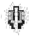
- a linear actuator according to a first embodiment of the present invention will hereinafter be described with reference to Fig. 1.
- a linear actuator of Fig. 1 generally comprises a stator assembly 60, a rotor assembly 70, an output shaft 80, a rear end cap 90; a front end protrusion 100; and a front end cap 110.
- the stator assembly 60 is composed of two stator units 63; 66, one 63 of which is structured such that two stator yokes 63a, 63b shaped into a ring oppose each other so as to sandwich therebetween a bobbin 62 having a winding 61 provided therearound, and the other 66 of which is structured such that two stator yokes 66a, 66b shaped into a ring oppose each other so as to sandwich therebetween a bobbin 65 having a winding 64 provided therearound, and the two stator units 63, 66 structured as above are coaxially stacked on each other forming a hollow-cylinder looking like a doughnut.
- the two stator yokes 63a, 63b of the stator unit 63 each have an array of pole teeth and are coupled to each other with their respective pole teeth intermeshing with each other.
- the two stator yokes 66a, 66b of the stator unit 66 each have an array of pole teeth and are coupled to each other with their respective pole teeth intermeshing with each other.
- respective pole teeth of the two stator units 63, 66 are appropriately shifted from each other for two-phase driving.
- the pole teeth constitute the inner circumference of the stator assembly 60.
- the windings 61, 64 are responsible for exciting the respective pole teeth of the stator units 63, 66.
- stator yokes 63a, 63b and 66a, 66b, and bobbins 62, 65 with the windings 61, 64 are integrally fixed together by means of a yoke support member 67 which is formed of resin by injection-molding.
- the rotor assembly 70 is housed in the stator assembly 60.
- the rotor assembly 70 is composed of a rotor magnet 71, a resin segment 72, and a female screw 73, and is shaped into a hollow-cylinder.
- the rotor magnet 71 is shaped in a ring, has a plurality of magnetic poles, and constitutes the outer circumference of the rotor assembly thus opposing the pole teeth of the stator assembly 60 with a predetermined gap therebetween.
- the resin segment 72 is shaped tube-like, and disposed inside the rotor magnet 71, and the female screw 73 is attached inside the resin segment 72 by means of resin injection-molding.
- the rear end cap 90 is positioned at a rear end face 60b of the stator assembly 60 and covers the hollow of the stator assembly 60.
- the rear end cap 90 is formed of resin simultaneously and integrally with the yoke support member 67 by resin injection-molding.
- the rear end cap 90 has a cavity 91 at its inner side facing the rotor assembly 70.
- the cavity 91 constitutes a sleeve bearing and supports rotatably a rear end portion 70b of the rotor assembly 70.
- the cavity 91 is not necessarily configured as shown in Fig. 1 but may alternatively be configured so as to receive a ball bearing fitted thereinto for rotatably supporting the rotor assembly 70.
- the output shaft 80 is shaped round in its cross section, has a male screw 81 formed at a portion toward a rear end 80b thereof, has a stopper pin 82 disposed at a portion toward a front end 80a, and has its rearward portion inserted through the rotor assembly 70.
- the male screw 81 engages threadedly with the female screw 73 of the rotor assembly 70, whereby the output shaft 80 travels in the axial direction linearly without turning or with less than one turn when the rotor assembly 70 rotates.
- the stopper pin 82 prohibits or restricts rotation of the output shaft 80 within one turn.
- the front end protrusion 100 is shaped into a ring and positioned at a front end face 60a of the stator assembly 60.
- the front end protrusion 100 is formed of resin simultaneously and integrally with the yoke support member 67 and also with the rear end cap 90 by resin injection-molding.
- the front end protrusion 100 has an inner diameter larger than the inner diameter of the stator assembly 60, and has a front ball bearing 101 fitted thereinto.
- a portion of the resin segment 72 of the rotor assembly 70 is fixedly fitted into the inner ring of the front ball bearing 101, whereby the front end portion of the rotor assembly 70 is rotatably supported.
- the front end protrusion 100 has a stopper member 103 attached to its frontward portion.
- the stopper member 103 is shaped into a disk, has a center hole for inserting the output shaft 80, and has a circular recess formed at its inner side facing the front ball bearing 101.
- the recess of the stopper member 103 defines a diameter larger than an outer diameter of the inner ring of the front ball bearing 101 thereby forming a clearance from the inner ring so as not to block the rotation of the rotor assembly 70.
- the output shaft 80 is caused to stop its rearward movement when the stopper pin 82 of the output shaft 80 touches the stopper member 103.
- the front end cap 110 is attached by means of a metal fitting 114 to the front end face 60a of the stator assembly 60 so as to cover the hollow of the stator assembly 60 housing the rotor assembly 70.
- the front end cap 110 has a round center hole 111, and the output shaft 80 is inserted through the center hole 111 so as to have its front end portion (toward the front end 80a) sticking out from the front end cap 110.
- the front end cap 110 has a groove 112 extending parallel to the length of the output shaft 80.
- the aforementioned stopper pin 82 is lodged in and guided by the groove 112 so as to prohibit or restrict rotation of the output shaft 80 and to restrict the travel distance of the output shaft 80.
- the linear actuator according to the first embodiment of the present invention includes the stopper member 103, and the output shaft 80 is caused to stop its rearward movement when the stopper pin 82 touches the stopper member 103.
- the female screw 73 does not touch the proximal end portion of the male screw 81 therefore eliminating the aforementioned screw biting problem
- the stopper pin 82 does not touch any portion of the rotor assembly 70 or the inner ring of the front ball bearing 101 therefore not requiring any extra torque for restarting the rotation of the rotor assembly 70.
- the stopper member 103 does not have any pointed portion therefore exhibiting little wear and keeping off damage, eventually resulting in a stable and accurate positioning control of the output shaft 80.
- FIG. 2 A linear actuator according to a second embodiment of the present invention will be described with reference to Fig. 2.
- like reference numerals refer to like elements in Fig. 1.
- the linear actuator according to the second embodiment differs from the first embodiment principally in bearing type, and in stopper member structure.
- the front and rear end portions of the rotor assembly 70 are rotatably supported respectively by the ball bearing 101 and the cavity 91 constituting a sleeve bearing, and the stopper member 103 is attached to the front end protrusion 100.
- the front and rear end portions of a rotor assembly are rotatably supported respectively by a sleeve bearing and a ball bearing (reversed compared with the first embodiment), and a stopper member is constituted by a portion of the sleeve bearing which rotatably supports the front end portion of the rotor assembly.
- the linear actuator according to the second embodiment shown in Fig. 2 basically comprises a stator assembly 60, a rotor assembly 70, and an output shaft 80, which are of the same structure as the first embodiment shown in Fig. 1.
- a rear end cap 120 is disposed at a rear end face 60b of the stator assembly 60 so as to cover the hollow of the stator assembly 60.
- the rear end cap 120 is formed of resin integrally with a yoke support member 67 by injection-molding, and has a cavity 121 at its inner side facing the rotor assembly 70.
- the cavity 121 has a circular recess formed coaxially therewith, and a rear ball bearing 122 to rotatably support a rear end 70b of the rotor assembly 70 is fitted into the recess.
- a front end cap 130 is attached at a front end face 60a of the stator assembly 60 so as to cover the hollow of the stator assembly 60 housing the rotor assembly 70.
- the front end cap 130 defines a cavity at its inner side facing the rotor assembly 70, and has a round center hole 131.
- a sleeve bearing 140 is fitted into the cavity of the front end cap 130 and supports rotatably a front end portion 70a of the rotor assembly 70, and the output shaft 80 is inserted through the center hole 131 so as to have its front end portion (toward a front end 80a) sticking out from the front end cap 130.
- the output shaft 80 is movably inserted through the sleeve bearing 140.
- the sleeve bearing 140 has a groove 141 formed at its inner circumference so as to extend parallel to the length of the output shaft 80.
- a frontward end of the groove 141 is open, and the other end is blind so as to constitute a stopper member 142.
- a stopper pin 82 is lodged in and guided by the groove 141 thereby controlling the movement of the output shaft 80.
- a front plate 150 may be attached as required.
- the linear actuator structured above actuates basically in the same way as the linear actuator of the first embodiment.
- the output shaft 80 moves linearly when the rotor assembly 70 rotates.
- the stopper pin 82 fixedly disposed at the output shaft 80 also moves linearly along the groove 141 while prohibiting or restricting the rotation of the output shaft 80.
- the stopper pin 82 moves also rearward, and the output shaft 80 stops its movement upon the stopper pin 82 touching the stopper member 142.
- the linear actuator according to the second embodiment of the present invention includes the stopper member 142, and the rotor assembly 70 is caused to stop its linear movement when the stopper pin 82 touches the stopper member 142.
- the female screw 73 does not touch the proximal end portion of the male screw 81 therefore eliminating the aforementioned screw biting problem
- the stopper pin 82 does not touch any portion of the rotor assembly 70 therefore not requiring any extra torque for duly restarting the rotation of the rotor assembly 70.
- the stopper member 142 does not have any pointed portion therefore exhibiting little wear and keeping from damage, eventually resulting in a stable and accurate positioning control of the output shaft 80.
Landscapes
- Engineering & Computer Science (AREA)
- Power Engineering (AREA)
- General Engineering & Computer Science (AREA)
- Mechanical Engineering (AREA)
- Transmission Devices (AREA)
- Connection Of Motors, Electrical Generators, Mechanical Devices, And The Like (AREA)
Abstract
Description
Claims (1)
- A linear actuator characterized by comprising:characterized in that the linear actuator further comprises a stopper member (103) which is disposed fixedly with respect to the stator assembly (60), and which stops axial movement of the output shaft (80) without making it happen that the stopper pin (82) which moves together with the output shaft (80) touches the rotor assembly (70).a stator assembly (60) shaped into a cylinder defining a hollow, the stator assembly (60) including
a plurality of windings (61, 64), and
a plurality of stator yokes each having an array of pole teeth which constitute an inner circumference of the stator assembly (60), and which are excited by the windings (61, 64);a rotor assembly (70) shaped into a hollow-cylinder, and rotatably housed in the hollow of the stator assembly (60), the rotor assembly (70) including
a ring-shaped magnet (71) having a plurality of magnetic poles, constituting an outer circumference of the rotor assembly (70), and opposing the pole teeth of the stator assembly (60) with a predetermined distance therebetween, and
a female screw (73) disposed at an inner circumference of the rotor assembly (70);an output shaft (80) having a male screw (81) formed at a rearward portion thereof and threadedly engaging with the female screw (73) of the rotator assembly (70), the output shaft being inserted through the rotor assembly (70); anda stopper pin (82) fixedly disposed at a frontward portion of the output shaft (80), and axially controlling mode and amount of movement of the output shaft (80) initiated by rotation of the rotor assembly (70),
Applications Claiming Priority (2)
| Application Number | Priority Date | Filing Date | Title |
|---|---|---|---|
| JP2003050097A JP4551623B2 (en) | 2003-02-26 | 2003-02-26 | Linear actuator |
| JP2003050097 | 2003-02-26 |
Publications (2)
| Publication Number | Publication Date |
|---|---|
| EP1453184A1 true EP1453184A1 (en) | 2004-09-01 |
| EP1453184B1 EP1453184B1 (en) | 2013-06-05 |
Family
ID=32767780
Family Applications (1)
| Application Number | Title | Priority Date | Filing Date |
|---|---|---|---|
| EP04004201.2A Expired - Lifetime EP1453184B1 (en) | 2003-02-26 | 2004-02-25 | Linear actuator having mechanism for stopping linear movement of output shaft without touching rotor |
Country Status (3)
| Country | Link |
|---|---|
| US (2) | US7268449B2 (en) |
| EP (1) | EP1453184B1 (en) |
| JP (1) | JP4551623B2 (en) |
Cited By (2)
| Publication number | Priority date | Publication date | Assignee | Title |
|---|---|---|---|---|
| FR2960515A1 (en) * | 2010-06-01 | 2011-12-02 | Sagem Defense Securite | Flight control actuator for controlling aileron of motor vehicle, has mechanical stops limiting translation of screw in given direction and including elements, where one of elements comprises damping unit to stop rotation of nut |
| EP2308156A4 (en) * | 2008-07-28 | 2014-02-19 | Lg Innotek Co Ltd | SCHRITTAKTOR |
Families Citing this family (16)
| Publication number | Priority date | Publication date | Assignee | Title |
|---|---|---|---|---|
| JP4681874B2 (en) * | 2004-12-24 | 2011-05-11 | キヤノン株式会社 | Drive device |
| DE202005003981U1 (en) * | 2005-03-12 | 2005-06-30 | Elero Gmbh | drive system |
| JP5233246B2 (en) * | 2007-10-31 | 2013-07-10 | 日本精工株式会社 | Electric telescopic adjustment type steering device |
| DE102008030016A1 (en) * | 2008-06-24 | 2009-12-31 | Schaeffler Kg | Linear actuator, in particular for adjusting the flaps in motor vehicle turbochargers |
| KR101543673B1 (en) * | 2009-04-08 | 2015-08-12 | 엘지이노텍 주식회사 | Linear Step Motor |
| JP5756304B2 (en) * | 2011-02-22 | 2015-07-29 | ミネベア株式会社 | Linear actuator |
| TW201419711A (en) * | 2012-11-06 | 2014-05-16 | Tricore Corp | Linear motor |
| JP6009919B2 (en) * | 2012-11-30 | 2016-10-19 | ミネベア株式会社 | Linear actuator |
| KR101987168B1 (en) * | 2012-12-17 | 2019-09-27 | 엘지이노텍 주식회사 | Screw motor and manufacturing method of the same of |
| US9711269B2 (en) * | 2014-01-08 | 2017-07-18 | Honeywell International Inc. | Torque motor actuator with an armature stop |
| KR101903616B1 (en) * | 2017-11-30 | 2018-10-04 | 엘지이노텍 주식회사 | Step actuator |
| CN109873402A (en) * | 2017-12-01 | 2019-06-11 | 睿能创意公司 | Hub unit, carrier and its guard method |
| TWI701176B (en) | 2017-12-01 | 2020-08-11 | 英屬開曼群島商睿能創意公司 | Hub apparatus and wheel |
| KR101971544B1 (en) * | 2018-09-21 | 2019-04-23 | 엘지이노텍 주식회사 | Step actuator |
| JP2021153375A (en) * | 2020-03-25 | 2021-09-30 | 日本電産コパル電子株式会社 | Linear drive device |
| CN111342608B (en) * | 2020-04-03 | 2022-01-14 | 嵊州市宏诺机电有限公司 | Motor, motor driving system, electric push rod and electric speed reducer |
Citations (3)
| Publication number | Priority date | Publication date | Assignee | Title |
|---|---|---|---|---|
| DE19730111A1 (en) * | 1997-01-28 | 1998-08-06 | Mitsubishi Electric Corp | Motor with conversion of a rotary motion into a reciprocating motion |
| JPH11155275A (en) | 1997-11-25 | 1999-06-08 | Asmo Co Ltd | Steeping motor, optical axis adjustment device and transfer range setting method |
| JP2001095192A (en) * | 1999-09-27 | 2001-04-06 | Asmo Co Ltd | Stepping motor and assembling method thereof |
Family Cites Families (26)
| Publication number | Priority date | Publication date | Assignee | Title |
|---|---|---|---|---|
| US3680761A (en) * | 1970-07-28 | 1972-08-01 | Kelsey Hayes Co | Fine wire butt welder |
| JPS5144067Y2 (en) * | 1972-01-24 | 1976-10-26 | ||
| JPS5146960B2 (en) | 1972-02-18 | 1976-12-11 | ||
| JPS5522851Y2 (en) * | 1975-03-05 | 1980-05-30 | ||
| JPS51111010A (en) | 1975-03-26 | 1976-10-01 | Toshiba Corp | Manuscipt display |
| JPS552285Y2 (en) * | 1975-08-27 | 1980-01-21 | ||
| US4412517A (en) * | 1980-10-06 | 1983-11-01 | Toyota Jidosha Kogyo Kabushiki Kaisha | Idling speed control device of an internal combustion engine |
| JPS60155051A (en) * | 1984-01-25 | 1985-08-14 | Matsushita Electric Ind Co Ltd | Electrically-driven rectilinear motion actuator |
| JPS6257582U (en) * | 1985-09-30 | 1987-04-09 | ||
| JPS6257561U (en) * | 1985-09-30 | 1987-04-09 | ||
| JP2515765Y2 (en) * | 1988-04-18 | 1996-10-30 | 愛三工業株式会社 | Electric motor |
| JP2797357B2 (en) * | 1988-12-29 | 1998-09-17 | 松下電器産業株式会社 | Linear motion motor |
| JP2581261B2 (en) * | 1990-04-27 | 1997-02-12 | ブラザー工業株式会社 | Step motor |
| JP2992729B2 (en) | 1993-05-17 | 1999-12-20 | ミネベア株式会社 | Linear actuator |
| JPH07274472A (en) * | 1994-03-24 | 1995-10-20 | Matsushita Electric Ind Co Ltd | Direct acting stepping motor |
| US6362547B1 (en) * | 1994-05-23 | 2002-03-26 | Tri-Tech, Inc. | Linear/rotary motor and method of use |
| DE19711851B4 (en) * | 1997-03-21 | 2005-09-22 | Continental Teves Ag & Co. Ohg | Brake actuator with parking brake for an electric brake system |
| US6081051A (en) * | 1998-05-13 | 2000-06-27 | Sanyo Denki Co., Ltd. | Linear/rotary actuator and winding machine including same |
| US6531798B1 (en) * | 1999-02-24 | 2003-03-11 | Tri-Tech, Inc | Linear/rotary motor and method of use |
| JP2000276927A (en) * | 1999-03-25 | 2000-10-06 | Asmo Co Ltd | Optical axis adjustment device |
| DE60030652T2 (en) * | 1999-04-20 | 2007-10-18 | Mitsubishi Denki K.K. | Motor shaft for rotary / direct control Motor converter and method for its manufacture |
| DE10014226A1 (en) * | 2000-03-22 | 2001-09-27 | Bosch Gmbh Robert | Electromechanical wheel brake has transversal flux motor with annular stimulation winding enclosing axis, yokes distributed peripherally on stimulation winding, matching movable poles |
| JP2002122203A (en) * | 2000-10-17 | 2002-04-26 | Minebea Co Ltd | Linear actuator |
| US6603229B1 (en) * | 2000-11-15 | 2003-08-05 | Tri-Tech, Inc. | Linear actuator with threaded captivation sleeve, captive lead screw, and spring pre-load adjustment |
| JP4136333B2 (en) * | 2001-06-13 | 2008-08-20 | 日本電産サンキョー株式会社 | Linear drive |
| JP3984180B2 (en) * | 2003-02-26 | 2007-10-03 | ミネベア株式会社 | Linear actuator, linear actuator manufacturing method, and linear actuator inspection method |
-
2003
- 2003-02-26 JP JP2003050097A patent/JP4551623B2/en not_active Expired - Fee Related
-
2004
- 2004-02-25 EP EP04004201.2A patent/EP1453184B1/en not_active Expired - Lifetime
- 2004-02-25 US US10/788,004 patent/US7268449B2/en not_active Expired - Lifetime
-
2007
- 2007-03-21 US US11/726,464 patent/US7564151B2/en not_active Expired - Lifetime
Patent Citations (3)
| Publication number | Priority date | Publication date | Assignee | Title |
|---|---|---|---|---|
| DE19730111A1 (en) * | 1997-01-28 | 1998-08-06 | Mitsubishi Electric Corp | Motor with conversion of a rotary motion into a reciprocating motion |
| JPH11155275A (en) | 1997-11-25 | 1999-06-08 | Asmo Co Ltd | Steeping motor, optical axis adjustment device and transfer range setting method |
| JP2001095192A (en) * | 1999-09-27 | 2001-04-06 | Asmo Co Ltd | Stepping motor and assembling method thereof |
Non-Patent Citations (2)
| Title |
|---|
| PATENT ABSTRACTS OF JAPAN vol. 1999, no. 11 30 September 1999 (1999-09-30) * |
| PATENT ABSTRACTS OF JAPAN vol. 2000, no. 21 30 August 2001 (2001-08-30) * |
Cited By (6)
| Publication number | Priority date | Publication date | Assignee | Title |
|---|---|---|---|---|
| EP2308156A4 (en) * | 2008-07-28 | 2014-02-19 | Lg Innotek Co Ltd | SCHRITTAKTOR |
| US8978496B2 (en) | 2008-07-28 | 2015-03-17 | Lg Innotek Co., Ltd. | Step actuator |
| US9625016B2 (en) | 2008-07-28 | 2017-04-18 | Lg Innotek Co., Ltd. | Step actuator |
| US10673299B2 (en) | 2008-07-28 | 2020-06-02 | Lg Innotek Co., Ltd. | Step actuator |
| US11799348B2 (en) | 2008-07-28 | 2023-10-24 | Lg Innotek Co., Ltd. | Step actuator |
| FR2960515A1 (en) * | 2010-06-01 | 2011-12-02 | Sagem Defense Securite | Flight control actuator for controlling aileron of motor vehicle, has mechanical stops limiting translation of screw in given direction and including elements, where one of elements comprises damping unit to stop rotation of nut |
Also Published As
| Publication number | Publication date |
|---|---|
| US7268449B2 (en) | 2007-09-11 |
| EP1453184B1 (en) | 2013-06-05 |
| US7564151B2 (en) | 2009-07-21 |
| JP2004257497A (en) | 2004-09-16 |
| JP4551623B2 (en) | 2010-09-29 |
| US20040164624A1 (en) | 2004-08-26 |
| US20070164622A1 (en) | 2007-07-19 |
Similar Documents
| Publication | Publication Date | Title |
|---|---|---|
| US7564151B2 (en) | Linear actuator having mechanism for stopping linear movement of output shaft without touching rotor | |
| US8503104B2 (en) | Motor having small size and high output, and light amount adjustment device equipped with the motor | |
| US7560836B2 (en) | Driving device and light amount adjusting device | |
| US20090096298A1 (en) | Linear-motion actuator | |
| JP2006291912A (en) | Motor driven throttle control device for internal combustion engine | |
| JP2009124868A (en) | Motor | |
| US6713936B2 (en) | Stepping motor | |
| KR20020050106A (en) | A motor | |
| US20100134906A1 (en) | Actuator for lens driving mechanism | |
| EP1445851A2 (en) | Motor | |
| KR100760229B1 (en) | Driving device and light amount controller | |
| JP5158534B2 (en) | Compound drive motor | |
| US8137011B2 (en) | Actuator and blade drive device for camera | |
| JP2002153012A (en) | Motor | |
| US20090206685A1 (en) | Motor device | |
| JP5958900B2 (en) | Cam drive actuator | |
| JP2007104849A (en) | Small stepping motor, drive mechanism having the same, and positioning mechanism | |
| JP4366788B2 (en) | Motor with linear drive mechanism | |
| JP2004320828A (en) | Drive | |
| JPH11122862A (en) | Motor | |
| JP5415751B2 (en) | Stepping motor | |
| JP2004254448A (en) | Actuator | |
| JP2009092102A (en) | Linear actuator | |
| JP4250312B2 (en) | Drive transmission device | |
| JPH0724933Y2 (en) | Thrust bearing mechanism for high speed motors |
Legal Events
| Date | Code | Title | Description |
|---|---|---|---|
| PUAI | Public reference made under article 153(3) epc to a published international application that has entered the european phase |
Free format text: ORIGINAL CODE: 0009012 |
|
| AK | Designated contracting states |
Kind code of ref document: A1 Designated state(s): AT BE BG CH CY CZ DE DK EE ES FI FR GB GR HU IE IT LI LU MC NL PT RO SE SI SK TR |
|
| AX | Request for extension of the european patent |
Extension state: AL LT LV MK |
|
| 17P | Request for examination filed |
Effective date: 20050113 |
|
| AKX | Designation fees paid |
Designated state(s): DE FR GB IT |
|
| RBV | Designated contracting states (corrected) |
Designated state(s): DE FR GB IT |
|
| 17Q | First examination report despatched |
Effective date: 20090121 |
|
| GRAP | Despatch of communication of intention to grant a patent |
Free format text: ORIGINAL CODE: EPIDOSNIGR1 |
|
| GRAS | Grant fee paid |
Free format text: ORIGINAL CODE: EPIDOSNIGR3 |
|
| GRAA | (expected) grant |
Free format text: ORIGINAL CODE: 0009210 |
|
| AK | Designated contracting states |
Kind code of ref document: B1 Designated state(s): DE FR GB IT |
|
| REG | Reference to a national code |
Ref country code: GB Ref legal event code: FG4D |
|
| REG | Reference to a national code |
Ref country code: DE Ref legal event code: R096 Ref document number: 602004042326 Country of ref document: DE Effective date: 20130801 |
|
| PLBE | No opposition filed within time limit |
Free format text: ORIGINAL CODE: 0009261 |
|
| STAA | Information on the status of an ep patent application or granted ep patent |
Free format text: STATUS: NO OPPOSITION FILED WITHIN TIME LIMIT |
|
| 26N | No opposition filed |
Effective date: 20140306 |
|
| PG25 | Lapsed in a contracting state [announced via postgrant information from national office to epo] |
Ref country code: IT Free format text: LAPSE BECAUSE OF FAILURE TO SUBMIT A TRANSLATION OF THE DESCRIPTION OR TO PAY THE FEE WITHIN THE PRESCRIBED TIME-LIMIT Effective date: 20130605 |
|
| REG | Reference to a national code |
Ref country code: DE Ref legal event code: R097 Ref document number: 602004042326 Country of ref document: DE Effective date: 20140306 |
|
| GBPC | Gb: european patent ceased through non-payment of renewal fee |
Effective date: 20140225 |
|
| REG | Reference to a national code |
Ref country code: FR Ref legal event code: ST Effective date: 20141031 |
|
| PG25 | Lapsed in a contracting state [announced via postgrant information from national office to epo] |
Ref country code: FR Free format text: LAPSE BECAUSE OF NON-PAYMENT OF DUE FEES Effective date: 20140228 Ref country code: GB Free format text: LAPSE BECAUSE OF NON-PAYMENT OF DUE FEES Effective date: 20140225 |
|
| REG | Reference to a national code |
Ref country code: DE Ref legal event code: R082 Ref document number: 602004042326 Country of ref document: DE Representative=s name: RUEGER | ABEL PATENT- UND RECHTSANWAELTE, DE Ref country code: DE Ref legal event code: R082 Ref document number: 602004042326 Country of ref document: DE Representative=s name: RUEGER, BARTHELT & ABEL PATENTANWAELTE, DE Ref country code: DE Ref legal event code: R081 Ref document number: 602004042326 Country of ref document: DE Owner name: MINEBEA MITSUMI INC., JP Free format text: FORMER OWNER: MINEBEA CO., LTD., MIYOTA-MACHI, NAGANO-GUN, JP Ref country code: DE Ref legal event code: R082 Ref document number: 602004042326 Country of ref document: DE Representative=s name: RUEGER ABEL PATENT- UND RECHTSANWAELTE, DE |
|
| PGFP | Annual fee paid to national office [announced via postgrant information from national office to epo] |
Ref country code: DE Payment date: 20220217 Year of fee payment: 19 |
|
| REG | Reference to a national code |
Ref country code: DE Ref legal event code: R119 Ref document number: 602004042326 Country of ref document: DE |
|
| PG25 | Lapsed in a contracting state [announced via postgrant information from national office to epo] |
Ref country code: DE Free format text: LAPSE BECAUSE OF NON-PAYMENT OF DUE FEES Effective date: 20230901 |