EP1453163A1 - Vehicular neutralizing apparatus - Google Patents
Vehicular neutralizing apparatus Download PDFInfo
- Publication number
- EP1453163A1 EP1453163A1 EP04250876A EP04250876A EP1453163A1 EP 1453163 A1 EP1453163 A1 EP 1453163A1 EP 04250876 A EP04250876 A EP 04250876A EP 04250876 A EP04250876 A EP 04250876A EP 1453163 A1 EP1453163 A1 EP 1453163A1
- Authority
- EP
- European Patent Office
- Prior art keywords
- vehicle
- occupant
- sensor
- ion generator
- vehicular
- Prior art date
- Legal status (The legal status is an assumption and is not a legal conclusion. Google has not performed a legal analysis and makes no representation as to the accuracy of the status listed.)
- Granted
Links
- 230000003472 neutralizing effect Effects 0.000 title claims description 14
- 150000002500 ions Chemical class 0.000 claims abstract description 88
- 238000006386 neutralization reaction Methods 0.000 claims abstract description 45
- 230000005611 electricity Effects 0.000 claims abstract description 18
- 230000003068 static effect Effects 0.000 claims abstract description 18
- 230000000694 effects Effects 0.000 description 7
- 238000001514 detection method Methods 0.000 description 2
- 238000010586 diagram Methods 0.000 description 2
- 230000015572 biosynthetic process Effects 0.000 description 1
- 230000002542 deteriorative effect Effects 0.000 description 1
- 238000003780 insertion Methods 0.000 description 1
- 230000037431 insertion Effects 0.000 description 1
- 238000012986 modification Methods 0.000 description 1
- 230000004048 modification Effects 0.000 description 1
- 239000002245 particle Substances 0.000 description 1
- 230000001012 protector Effects 0.000 description 1
- 230000000717 retained effect Effects 0.000 description 1
Images


Classifications
-
- H—ELECTRICITY
- H01—ELECTRIC ELEMENTS
- H01T—SPARK GAPS; OVERVOLTAGE ARRESTERS USING SPARK GAPS; SPARKING PLUGS; CORONA DEVICES; GENERATING IONS TO BE INTRODUCED INTO NON-ENCLOSED GASES
- H01T23/00—Apparatus for generating ions to be introduced into non-enclosed gases, e.g. into the atmosphere
Definitions
- the present invention relates to a vehicular neutralizing apparatus and, more particularly, to a vehicular neutralizing apparatus for neutralizing static electricity charged in a vehicle or an occupant.
- Japanese Patent Application Laid-Open Publication No. 2002-178859 discloses a neutralizing apparatus.
- a proposal has been made to provide a structure wherein a vehicle is installed with an ion generator for generating ions to permit the ion generator to release the ions toward an occupant when the occupant operates a door lock button or a door knob sensor for thereby neutralizing the static electricity charged in the occupant.
- the ion generator has no choice but to be disposed in a relatively low position such as a vicinity of the door knob or a vicinity of an insertion port of an ignition key, resulting in a tendency of an inability of efficiently performing neutralization.
- the ions generating from the ion generator is hard to adequately impinge upon a whole (especially the shoulder or the arms) of the human body of the occupant and it is conceivable that it takes an extended period of time for neutralizing charged particles or inadequate neutralizing result is caused, deteriorating neutralizing efficiency.
- the present invention has been completed upon such studies conducted by the present inventors and has an object to provide a vehicular neutralizing apparatus that is able to efficiently neutralize static electricity charged in an occupant.
- a vehicular neutralization apparatus comprises: an ion generator disposed on at least one of a roof of a vehicle and an area in a vicinity of the roof inside the vehicle to allow ions, generated with the ion generator, to be oriented toward an occupant, thereby neutralizing static electricity charged to the occupant.
- a vehicular neutralization apparatus comprises: ion generating means, disposed on at least one of a roof of a vehicle and an area in a vicinity of the roof inside the vehicle, for generating ions; and controlling means for controlling the ion generating means to supply the ions, generated by the ion generating means, toward an occupant, thereby neutralizing static electricity charged to the occupant.
- FR designates the frontward of a vehicle body
- R the rightward of the vehicle body
- URR the upward of the vehicle
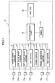
- Fig. 1 is a block diagram showing a schematic structure of the vehicular neutralization apparatus of the presently filed embodiment
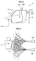
- Fig. 2 is a view showing one example of a location of a vehicle V to which an ion generator of such a vehicular neutralization apparatus is installed, with a vehicle compartment of a vehicle being observed in a forward direction
- Fig. 3 is a view showing another example of a location of the vehicle V to which the ion generator of such a vehicular neutralization apparatus is installed, with the vehicle compartment of the vehicle being observed in a rightward direction.
- the vehicular neutralization apparatus S is comprised of a door lock sensor 11 that detects whether a door lock button 11a inside the vehicle is operated, an external door knob sensor 12 that detects whether an external door knob 12a outside the vehicle is operated, an internal door knob sensor 13 that detects whether an internal door knob 13a inside the vehicle is operated, an ignition sensor 14 that detects whether an ignition 14a of the vehicle is actuated, a speed sensor 15 that detects a vehicle speed, a pressure sensitive sensor 16 that detects whether an occupant, such as a driver, rests on a seat 16a, and a PKB (parking brake) sensor 17 that detect whether a parking brake 17a remains actuated.
- a door lock sensor 11 that detects whether a door lock button 11a inside the vehicle is operated
- an external door knob sensor 12 that detects whether an external door knob 12a outside the vehicle is operated
- an internal door knob sensor 13 that detects whether an internal door knob 13a inside the vehicle is operated
- an ignition sensor 14 that detects whether an ignition 14a of the vehicle is
- a neutralization controller 18 is provided, and the door lock sensor 11, the outside knob sensor 12, the inside knob sensor 13, the ignition sensor 14, the speed sensor 15, the pressure sensitive sensor 16, and the PKB sensor 17 are electrically connected to the neutralization controller 18. Moreover, electrically connected to the neutralization controller 18 are a timer 19 and an ion generator 20.
- Fig. 1 in a case where the vehicle includes a passenger car, although typical pluralities of door lock sensors 11, external door knob sensors 12, internal door knob sensors 13,and pressure sensitive sensors 16 can be located at positions corresponding to a driver's seat, an assistant driver's seat,and left and right rear seats, respectively, only one of the sensors for each position is shown in Fig. 1 for the sake of convenience of description.
- the ion generators 20 are mounted to a location A in the vicinity of a room lamp 21 mounted to a central area of a ceiling (head lining) HL disposed inside of the vehicle compartment of a roof RO of the vehicle, a location B in the vicinity of a map lamp 23 mounted to the ceiling HL at an area rearward of a back mirror 22 in front of the ceiling HL and forward of the room lamp 21, and a location C inside of and upward of a front pillar 24, respectively.
- a location A in the vicinity of a room lamp 21 mounted to a central area of a ceiling (head lining) HL disposed inside of the vehicle compartment of a roof RO of the vehicle
- a location B in the vicinity of a map lamp 23 mounted to the ceiling HL at an area rearward of a back mirror 22 in front of the ceiling HL and forward of the room lamp 21, and a location C inside of and upward of a front pillar 24, respectively.
- the ion generators 20 are mounted to a location D inside of and upward of a center pillar 25 and a location E in the vicinity of an assist grip 26, to be gripped by an occupant, that is mounted to the ceiling HL at an area between the front pillar 24 and the center pillar 25, respectively. That is, such locations A to E are positioned in the vicinity of an operation objective to be operated by the occupant P (such as the driver) and an objective region by which the occupant passes during getting off the vehicle. Namely, such locations A to E are determined in consideration of motional posture of the occupant, especially, motional posture of the driver or passenger due to his action or behavior during getting on or getting off the vehicle.
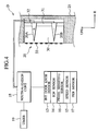
- Fig. 4 typically shows a structural view of the ion generator 20 located inside and upward of a right center pillar 25 of the vehicle
- Fig. 5 is a schematic view illustrating orientations of a positive electrode and a negative electrode of the ion generator 20.
- the ion generator 20 includes a pair of electrodes in general, more particularly, as shown in Fig. 4, the ion generator 20 located inside and upward of the center pillar 25 is comprised of a pair of a positive electrode 20A that contributes to emit positive ions and a negative electrode 20B that contributesto emit negative ions.
- Each of the positive electrode 20A and the negative electrode 20B has a sharpened distal end, with the positive electrode 20A and the negative electrode 20B disposed in opposition to one another.
- a small spatial area 30 Formed inward of and upward of the center pillar 25 is a small spatial area 30 in which the cone-shaped positive electrode 20A and negative electrode 20B are accommodated. Disposed in the small spatial area 30 in a vertical direction is a support plate 31 on which base portions of the positive electrode 20A and the negative electrode 20B are fixedly retained. Also, connected to the base portions of the positive electrode 20A and the negative electrode 20B, respectively, are ends of lead wires 32 whose other ends are connected to the neutralization controller 18.
- an open end of the spatial area 30, in which the positive electrode 20A and the negative electrode 20B are accommodated is oriented forward of the vehicle compartment and, so, covered with an electrode protector cover 33, avoiding the distal ends of the positive electrode 20A and the negative electrode 20B from hitting the occupant or an obstacle.
- the positive electrode 20A is placed upward and the negative electrode 20B is placed downward
- an alternative may be such that the positive electrode 20A is disposed downward and the negative electrode 20B is placed upward.
- the ion generators 20 to be placed in the vicinity A of the room lamp 21, the vicinity B of the map lamp 23, the inside and upper C of the front pillar 24, and the vicinity E of the assist grip 26 have structures typically similar in principle to that of Fig. 4.
- the positive electrode 20A and the negative electrode 20B have distal end portions oriented toward the occupant who gets on or gets off the vehicle. That is, as shown in Fig. 5, the positive electrode 20A and the negative electrode 20B mounted in the inside and upper D of the center pillar 25 have the distal end portions oriented forward of the vehicle. Also, with respect to the positive electrode 20A and the negative electrode 20B mounted in the vicinity E of the assist grip 26, the distal end portions of these components are oriented downward.
- the door lock sensor 11, the external door knob sensor 12, the internal door knob sensor 13, the ignition sensor 14, the speed sensor 15, the pressure sensitive sensor 16, and the PKB sensor 17 form detection means, and the neutralization controller 18 forms a neutralization control means.
- the occupant such as the driver, is charged with positive or negative static electricity due to friction of clothes.
- the occupant touches the door knob of the vehicle with an attempt to get off the vehicle under such a charged condition, the charged static electricity discharges, causing the occupant to encounter discomfort feeling.
- the occurrence of the occupant attempting to get off the vehicle or the situation of the occupant remaining in the course of getting off the vehicle are detected by the door lock sensor 11, the external door knob sensor 12, the internal door knob sensor 13, the ignition sensor 14, the speed sensor 15, the pressure sensitive sensor 16,and the PKB sensor 17.
- the door lock sensor 11 the external door knob sensor 12
- the internal door knob sensor 13 the ignition sensor 14
- the speed sensor 15 the pressure sensitive sensor 16,and the PKB sensor 17.
- the occurrence of the occupant attempting to get off the vehicle and the situation of the occupant remaining in the course of getting off the vehicle are detected using one of these sensors or using a suitable combination of these sensors.
- these operations may be detected by the door lock sensor 11 and the internal door knob sensor 13, respectively.
- the occurrence of such status may be detected by the speed sensor 15 and, further, since the engine is stopped, the occurrence of such status may be detected by the ignition sensor 14.
- the occurrence of such status may be detected by the PKB sensor 17 and, further, since the occupant leaves from the seat, the occurrence of such status may be detected by the pressure sensitive sensor 16.
- the occurrence of the person outside the vehicle operating the external door knob may be detected by the external door knob sensor 12.
- the timer 19 is activated and the neutralization controller 18 discriminates whether a certain time interval has elapsed after receiving a signal from the timer 19. Then, upon elapse of the certain time interval, the neutralization controller 18 interrupts the ion generators 20 from emitting and supplying the ions.
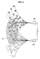
- Fig. 6 is a schematic view illustrating a neutralization effect as a results of the ions emitted from the positive electrode and the negative electrode of one ion generator 20.
- the ion generator 20 operates such that, as shown in Fig. 6, typically, the positive ions (+) are emitted from the positive electrode 20A and the negative ions (-) are emitted from the negative electrode 20B due to electrical action such as Coulomb force. And, if the occupant P is charged with the positive ions, the negative ions are oriented to the occupant, with the negative ions being coupled with the charges of positive ions. This results in neutralization of the occupant.
- the positive ions emitted from the positive electrode 20A and the negative ions emitted from the negative electrode 20B mutually attract each other, resulting in formation of an area (area effective for neutralization) 36 in which the positive ions and the negative ions are present. If an object (occupant) to be neutralized is present in such an area 36, the object to be neutralized can be neutralized even in the presence of any of the positively or negatively charged statuses.
- the presence of the positive electrode 20A and the negative electrode 20B having the distal end portions oriented toward the occupant who gets on or gets off the vehicle enables the static electricity, charged to the object to be neutralized, to be efficiently neutralized.
- a distance between the positive electrode 20A and the negative electrode 20B should fall in a certain range.
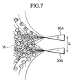
- Fig. 7 is a schematic view illustrating a neutralization effect in a case resulting from a shortened distance between the positive electrode and the negative electrode of one ion generator
- Fig. 8 is a schematic view illustrating a neutralization effect in a case resulting from a lengthened distance between the positive electrode and the negative electrode.
- the presently filed embodiment allows the distance L between the positive electrode 20A and the negative electrode 20B to be set to a value equal to or greater than 50 mm and equal to or less than 100 mm. That is to say, in the vehicle such as the passenger car, the presence of the distance L between the positive electrode 20A and the negative electrode 20B lying in the value less than 50 mm cause the area 36 effective for neutralization to have an excessively narrowed range and, in contrast, the presence of the distance L exceeding the value of 100 mm causes the ion density in such an area 36 to be in shortage, with both cases resulting to be of no practical use.
- the ion generators 20 are disposed in at least one of the vicinity A of the room lamp 21, the vicinity B of the map lamp 23, the inside and upper C of the front pillar 24, the inside and upper D of the center pillar 25, and the vicinity E of the assist grip 26 such that the ion generator is placed in the ceiling, that is, the roof or the vicinity of the roof, the ions emitted from the respective ion generators 20 can be adequately brought into impingement with a whole body, inclusive of a shoulder and arms, of the occupant for thereby enabling to efficiently neutralize the static electricity charged to the occupant.
- distal end portion of the positive electrode 20A and the distal end portion of the positive electrode 20B of such an ion generator 20 are oriented toward the occupant who gets on or gets off the vehicle, it is possible to efficiently neutralize the static electricity charged to the occupant.
- any one of or a combination of these sensors enables the occurrence of the occupant getting off the vehicle to be detected.
- the ion generators 20 may be merely located in any one of or in combination of the vicinity A of the room lamp 21, the vicinity B of the map lamp 23, the inside and upper C of the front pillar 24, the inside and upper D of the center pillar 25,and the vicinity E of the assist grip 26.
- the ion generators 20 may be located in the ceiling, that is, the roof or the vicinity of the roof, at areas other than the vicinity A of the room lamp 21, the vicinity B of the map lamp 23, the inside and upper C of the front pillar 24, the inside and upper D of the center pillar 25, and the vicinity E of the assist grip 26.
Landscapes
- Air-Conditioning For Vehicles (AREA)
- Elimination Of Static Electricity (AREA)
Abstract
Description
- The present invention relates to a vehicular neutralizing apparatus and, more particularly, to a vehicular neutralizing apparatus for neutralizing static electricity charged in a vehicle or an occupant.
- As a dry condition with a low humidity continues, static electricity is liable to be charged in a charging body, such as an occupant or a vehicle, causing various troubles to occur due to static electricity. If a back of the occupant is rubbed against a seat during drive of the vehicle, a human body, clothes, and shoes are charged with static electricity due to friction. Further, when attempting todrive the vehicle under fine weather, the vehicle is charged with static electricity due to friction between tires and the ground and friction between a vehicle body and air. Under such a state, if the occupant touches a door knob of the vehicle, the charged static electricity is discharged, resulting in occurrence of discomfort feeling.
- Japanese Patent Application Laid-Open Publication No. 2002-178859 discloses a neutralizing apparatus. According to such a disclosure, in Fig. 1 and related description, as a countermeasure to alleviate the discomfort feeling of the occupant, a proposal has been made to provide a structure wherein a vehicle is installed with an ion generator for generating ions to permit the ion generator to release the ions toward an occupant when the occupant operates a door lock button or a door knob sensor for thereby neutralizing the static electricity charged in the occupant.
- However, upon careful studies undertaken by the present inventors, with such a structure, since no consideration is substantially undertaken for the structure per se or additionally for motional posture of the occupant getting on and off the vehicle, the ion generator has no choice but to be disposed in a relatively low position such as a vicinity of the door knob or a vicinity of an insertion port of an ignition key, resulting in a tendency of an inability of efficiently performing neutralization. That is, if the ion generator is merely placed in the relatively low area, the ions generating from the ion generator is hard to adequately impinge upon a whole (especially the shoulder or the arms) of the human body of the occupant and it is conceivable that it takes an extended period of time for neutralizing charged particles or inadequate neutralizing result is caused, deteriorating neutralizing efficiency.
- Therefore, the present invention has been completed upon such studies conducted by the present inventors and has an object to provide a vehicular neutralizing apparatus that is able to efficiently neutralize static electricity charged in an occupant.
- In one aspect according to the present invention, a vehicular neutralization apparatus comprises: an ion generator disposed on at least one of a roof of a vehicle and an area in a vicinity of the roof inside the vehicle to allow ions, generated with the ion generator, to be oriented toward an occupant, thereby neutralizing static electricity charged to the occupant.
- In other words, in another aspect according to the present invention, a vehicular neutralization apparatus comprises: ion generating means, disposed on at least one of a roof of a vehicle and an area in a vicinity of the roof inside the vehicle, for generating ions; and controlling means for controlling the ion generating means to supply the ions, generated by the ion generating means, toward an occupant, thereby neutralizing static electricity charged to the occupant.
- Other and further features, advantages, and benefits of the present invention will become more apparent from the following description taken in conjunction with the following drawings.
-
- Fig. 1 is a block diagram showing a schematic structure of a vehicular neutralization apparatus of a first embodiment according to the present invention;
- Fig. 2 is a view showing one example of a location of a vehicle to which the ion generator of the vehicular neutralization apparatus is installed, in the first embodiment;
- Fig. 3 is a view showing another example of a location of a vehicle to which the ion generator of the vehicular neutralization apparatus is installed, in the first embodiment;
- Fig. 4 shows a structural view of the ion generator representatively located inside and upward of a right center pillar of the vehicle, in the first embodiment;
- Fig. 5 is a schematic view representatively illustrating orientations of a positive electrode and a negative electrode of the ion generator, in the first embodiment;
- Fig. 6 is a schematic view illustrating a neutralization effect as a results of the ions emitted from the positive electrode and the negative electrode of the ion generator, in the first embodiment;
- Fig. 7 is a schematic view illustrating a neutralization effect in a case resulting from a shortened distance between the positive electrode and the negative electrode of the ion generator, in the first embodiment; and
- Fig. 8 is a schematic view illustrating a neutralization effect in a case resulting from a lengthened distance between the positive electrode and the negative electrode of the ion generator.
-
- Hereunder, a vehicular neutralization apparatus of an embodiment according to the present invention is described below in detail with reference to the accompanying drawings. Also, throughout the drawings, reference symbol "FR" designates the frontward of a vehicle body, "R" the rightward of the vehicle body, and "UPR" the upward of the vehicle, respectively.
- Fig. 1 is a block diagram showing a schematic structure of the vehicular neutralization apparatus of the presently filed embodiment; Fig. 2 is a view showing one example of a location of a vehicle V to which an ion generator of such a vehicular neutralization apparatus is installed, with a vehicle compartment of a vehicle being observed in a forward direction; and Fig. 3 is a view showing another example of a location of the vehicle V to which the ion generator of such a vehicular neutralization apparatus is installed, with the vehicle compartment of the vehicle being observed in a rightward direction.
- As shown in Fig. 1, the vehicular neutralization apparatus S is comprised of a
door lock sensor 11 that detects whether adoor lock button 11a inside the vehicle is operated, an externaldoor knob sensor 12 that detects whether an external door knob 12a outside the vehicle is operated, an internaldoor knob sensor 13 that detects whether aninternal door knob 13a inside the vehicle is operated, anignition sensor 14 that detects whether anignition 14a of the vehicle is actuated, aspeed sensor 15 that detects a vehicle speed, a pressuresensitive sensor 16 that detects whether an occupant, such as a driver, rests on aseat 16a, and a PKB (parking brake)sensor 17 that detect whether aparking brake 17a remains actuated. - Further, a
neutralization controller 18 is provided, and thedoor lock sensor 11, theoutside knob sensor 12, theinside knob sensor 13, theignition sensor 14, thespeed sensor 15, the pressuresensitive sensor 16, and thePKB sensor 17 are electrically connected to theneutralization controller 18. Moreover, electrically connected to theneutralization controller 18 are atimer 19 and anion generator 20. - Incidentally, in a case where the vehicle includes a passenger car, although typical pluralities of
door lock sensors 11, externaldoor knob sensors 12, internaldoor knob sensors 13,and pressuresensitive sensors 16 can be located at positions corresponding to a driver's seat, an assistant driver's seat,and left and right rear seats, respectively, only one of the sensors for each position is shown in Fig. 1 for the sake of convenience of description. - On the driver's seat side, as shown in FIG. 2, the
ion generators 20 are mounted to a location A in the vicinity of aroom lamp 21 mounted to a central area of a ceiling (head lining) HL disposed inside of the vehicle compartment of a roof RO of the vehicle, a location B in the vicinity of amap lamp 23 mounted to the ceiling HL at an area rearward of aback mirror 22 in front of the ceiling HL and forward of theroom lamp 21, and a location C inside of and upward of afront pillar 24, respectively. Additionally, as shown in Fig. 3, theion generators 20 are mounted to a location D inside of and upward of acenter pillar 25 and a location E in the vicinity of anassist grip 26, to be gripped by an occupant, that is mounted to the ceiling HL at an area between thefront pillar 24 and thecenter pillar 25, respectively. That is, such locations A to E are positioned in the vicinity of an operation objective to be operated by the occupant P (such as the driver) and an objective region by which the occupant passes during getting off the vehicle. Namely, such locations A to E are determined in consideration of motional posture of the occupant, especially, motional posture of the driver or passenger due to his action or behavior during getting on or getting off the vehicle. - Fig. 4 typically shows a structural view of the
ion generator 20 located inside and upward of aright center pillar 25 of the vehicle, and Fig. 5 is a schematic view illustrating orientations of a positive electrode and a negative electrode of theion generator 20. - Although the
ion generator 20 includes a pair of electrodes in general, more particularly, as shown in Fig. 4, theion generator 20 located inside and upward of thecenter pillar 25 is comprised of a pair of apositive electrode 20A that contributes to emit positive ions and anegative electrode 20B that contributesto emit negative ions. Each of thepositive electrode 20A and thenegative electrode 20B has a sharpened distal end, with thepositive electrode 20A and thenegative electrode 20B disposed in opposition to one another. - Formed inward of and upward of the
center pillar 25 is a smallspatial area 30 in which the cone-shapedpositive electrode 20A andnegative electrode 20B are accommodated. Disposed in the smallspatial area 30 in a vertical direction is asupport plate 31 on which base portions of thepositive electrode 20A and thenegative electrode 20B are fixedly retained. Also, connected to the base portions of thepositive electrode 20A and thenegative electrode 20B, respectively, are ends oflead wires 32 whose other ends are connected to theneutralization controller 18. - Further, an open end of the
spatial area 30, in which thepositive electrode 20A and thenegative electrode 20B are accommodated, is oriented forward of the vehicle compartment and, so, covered with anelectrode protector cover 33, avoiding the distal ends of thepositive electrode 20A and thenegative electrode 20B from hitting the occupant or an obstacle. - Incidentally, in Fig. 4, although the
positive electrode 20A is placed upward and thenegative electrode 20B is placed downward, of course, an alternative may be such that thepositive electrode 20A is disposed downward and thenegative electrode 20B is placed upward. Moreover, theion generators 20 to be placed in the vicinity A of theroom lamp 21, the vicinity B of themap lamp 23, the inside and upper C of thefront pillar 24, and the vicinity E of theassist grip 26 have structures typically similar in principle to that of Fig. 4. - The
positive electrode 20A and thenegative electrode 20B have distal end portions oriented toward the occupant who gets on or gets off the vehicle. That is, as shown in Fig. 5, thepositive electrode 20A and thenegative electrode 20B mounted in the inside and upper D of thecenter pillar 25 have the distal end portions oriented forward of the vehicle. Also, with respect to thepositive electrode 20A and thenegative electrode 20B mounted in the vicinity E of theassist grip 26, the distal end portions of these components are oriented downward. Although not shown, such a situation can be similarly applied to the positive electrodes and the negative electrodes mounted in the vicinity A of theroom lamp 21, the vicinity B of themap lamp 23, and the inside and upper C of thefront pillar 24, with the distal end portions of these components being oriented toward the occupant who gets on or gets off the vehicle. - Incidentally, in the presently filed embodiment, the
door lock sensor 11, the externaldoor knob sensor 12, the internaldoor knob sensor 13, theignition sensor 14, thespeed sensor 15, the pressuresensitive sensor 16, and thePKB sensor 17 form detection means, and theneutralization controller 18 forms a neutralization control means. - Now, operation of the vehicular neutralization apparatus with the structure set forth above is described below.
- Suppose the occupant, such as the driver, is charged with positive or negative static electricity due to friction of clothes. In general, if the occupant touches the door knob of the vehicle with an attempt to get off the vehicle under such a charged condition, the charged static electricity discharges, causing the occupant to encounter discomfort feeling.
- However, with the vehicular neutralization apparatus of the presently filed embodiment, the occurrence of the occupant attempting to get off the vehicle or the situation of the occupant remaining in the course of getting off the vehicle are detected by the
door lock sensor 11, the externaldoor knob sensor 12, the internaldoor knob sensor 13, theignition sensor 14, thespeed sensor 15, the pressuresensitive sensor 16,and thePKB sensor 17. Of course, it may be arranged that the occurrence of the occupant attempting to get off the vehicle and the situation of the occupant remaining in the course of getting off the vehicle are detected using one of these sensors or using a suitable combination of these sensors. - For example, when attempting to get off the vehicle, since the occupant unlocks the door knob and consecutively operates the door knob, these operations may be detected by the
door lock sensor 11 and the internaldoor knob sensor 13, respectively. - Further, when attempting to get off the vehicle, since the vehicle comes to halt with the vehicle speed zeroing, the occurrence of such status may be detected by the
speed sensor 15 and, further, since the engine is stopped, the occurrence of such status may be detected by theignition sensor 14. - Furthermore, when attempting to get off the vehicle, since the parking brake is applied, the occurrence of such status may be detected by the
PKB sensor 17 and, further, since the occupant leaves from the seat, the occurrence of such status may be detected by the pressuresensitive sensor 16. - In addition, in a case where the occupant does not operate the external door knob while the other person outside the vehicle operates the external door knob to allow the occupant to get off the vehicle, the occurrence of the person outside the vehicle operating the external door knob may be detected by the external
door knob sensor 12. - And, suppose that all the sensors are reacted, respective detection signals resulting from the
door lock sensor 11, the externaldoor knob sensor 12, the internaldoor knob sensor 13, theignition sensor 14, thespeed sensor 15, the pressuresensitive sensor 16, and thePKB sensor 17 are applied to theneutralization controller 18, which is responsive to these input signals and controls theion generators 20 disposed in various parts, thereby causingion generators 20 to emit and supply ions. - As
such ion generators 20 begin to emit and supply the ions, thetimer 19 is activated and theneutralization controller 18 discriminates whether a certain time interval has elapsed after receiving a signal from thetimer 19. Then, upon elapse of the certain time interval, theneutralization controller 18 interrupts theion generators 20 from emitting and supplying the ions. - Fig. 6 is a schematic view illustrating a neutralization effect as a results of the ions emitted from the positive electrode and the negative electrode of one
ion generator 20. - In particular, the
ion generator 20 operates such that, as shown in Fig. 6, typically, the positive ions (+) are emitted from thepositive electrode 20A and the negative ions (-) are emitted from thenegative electrode 20B due to electrical action such as Coulomb force. And, if the occupant P is charged with the positive ions, the negative ions are oriented to the occupant, with the negative ions being coupled with the charges of positive ions. This results in neutralization of the occupant. - When this takes place, the positive ions emitted from the
positive electrode 20A and the negative ions emitted from thenegative electrode 20B mutually attract each other, resulting in formation of an area (area effective for neutralization) 36 in which the positive ions and the negative ions are present. If an object (occupant) to be neutralized is present in such anarea 36, the object to be neutralized can be neutralized even in the presence of any of the positively or negatively charged statuses. - Further, the presence of the
positive electrode 20A and thenegative electrode 20B having the distal end portions oriented toward the occupant who gets on or gets off the vehicle enables the static electricity, charged to the object to be neutralized, to be efficiently neutralized. - Here, a distance between the
positive electrode 20A and thenegative electrode 20B should fall in a certain range. - Fig. 7 is a schematic view illustrating a neutralization effect in a case resulting from a shortened distance between the positive electrode and the negative electrode of one ion generator, and Fig. 8 is a schematic view illustrating a neutralization effect in a case resulting from a lengthened distance between the positive electrode and the negative electrode.
- As shown in Fig. 7, in the case where the distance between the
positive electrode 20A and thenegative electrode 20B is shortened, although an ion density to be effective for neutralization in thearea 36 is intensified, the positive ions and the negative ions are liable to be coupled to one another and, hence, the range of thearea 36 is narrowed. - On the contrary, as shown in Fig. 8, in the case where the distance between the
positive electrode 20A and thenegative electrode 20B is lengthened, although thearea 36 has a widened range, the ion density in thearea 36 is minimized and, hence, it becomes difficult to efficiently perform neutralization. - Thus, in view of the presence in which the distance L between the
positive electrode 20A and thenegative electrode 20B has a remarkable effect on a performance of the neutralization apparatus, the presently filed embodiment allows the distance L between thepositive electrode 20A and thenegative electrode 20B to be set to a value equal to or greater than 50 mm and equal to or less than 100 mm. That is to say, in the vehicle such as the passenger car, the presence of the distance L between thepositive electrode 20A and thenegative electrode 20B lying in the value less than 50 mm cause thearea 36 effective for neutralization to have an excessively narrowed range and, in contrast, the presence of the distance L exceeding the value of 100 mm causes the ion density in such anarea 36 to be in shortage, with both cases resulting to be of no practical use. - As set forth above, with the structure of the presently filed embodiment, since the
ion generators 20 are disposed in at least one of the vicinity A of theroom lamp 21, the vicinity B of themap lamp 23, the inside and upper C of thefront pillar 24, the inside and upper D of thecenter pillar 25, and the vicinity E of theassist grip 26 such that the ion generator is placed in the ceiling, that is, the roof or the vicinity of the roof, the ions emitted from therespective ion generators 20 can be adequately brought into impingement with a whole body, inclusive of a shoulder and arms, of the occupant for thereby enabling to efficiently neutralize the static electricity charged to the occupant. - Further, since the distal end portion of the
positive electrode 20A and the distal end portion of thepositive electrode 20B of such anion generator 20 are oriented toward the occupant who gets on or gets off the vehicle, it is possible to efficiently neutralize the static electricity charged to the occupant. - Also, while the presently filed embodiment set forth above is arranged to detect the occurrence of the occupant getting off the vehicle using the
door lock sensor 11, the externaldoor knob sensor 12, the internaldoor knob sensor 13, theignition sensor 14, thespeed sensor 15, the pressuresensitive sensor 16, and thePKB sensor 17, any one of or a combination of these sensors enables the occurrence of the occupant getting off the vehicle to be detected. - Furthermore, it may be suffice for the
ion generators 20 to be merely located in any one of or in combination of the vicinity A of theroom lamp 21, the vicinity B of themap lamp 23, the inside and upper C of thefront pillar 24, the inside and upper D of thecenter pillar 25,and the vicinity E of theassist grip 26. - Moreover, the
ion generators 20 may be located in the ceiling, that is, the roof or the vicinity of the roof, at areas other than the vicinity A of theroom lamp 21, the vicinity B of themap lamp 23, the inside and upper C of thefront pillar 24, the inside and upper D of thecenter pillar 25, and the vicinity E of theassist grip 26. - Also, while the presently filed embodiment has been described in respect of the occupant getting off the vehicle, it is, of course, possible to apply the present invention to a case of the vehicle occupant getting on the vehicle if desired.
- Although the invention has been described above by reference to a certain embodiment of the invention, the invention is not limited to the embodiment described above. Modifications and variations of the embodiment described above will occur to those skilled in the art, in light of the teachings. The scope of the invention is defined with reference to the following claims.
Claims (10)
- A vehicular neutralization apparatus comprising:an ion generator (20) disposed on at least one of a roof (RO) of a vehicle and an area in a vicinity of the roof inside the vehicle to allow ions, generated with the ion generator, to be oriented toward an occupant (P), thereby neutralizing static electricity charged to the occupant.
- The vehicular neutralization apparatus according to claim 1, further comprising a controller (18) controlling the ion generator (20) so as to cause the ions generated with the ion generator to be supplied toward the occupant for thereby neutralizing static electricity charged to the occupant.
- The vehicular neutralization apparatus according to claim 2, further comprising a sensor (11 to 17) detecting the occupant getting on and off the vehicle,
wherein the controller (18) controls the ion generator in response to the sensor detecting the occupant getting on and off the vehicle. - The vehicular neutralization apparatus according to claim 3, wherein the sensor includes at least one of a door lock sensor (11) detecting a door lock button of the vehicle being actuated, an external door knob sensor (12) detecting an external door knob of the vehicle being actuated, an internal door knob sensor (13) detecting an internal door knob of the vehicle being actuated, an ignition sensor (14) detecting an ignition of the vehicle being actuated, a speed sensor (15) detecting a vehicle speed, a pressure sensitive sensor (16) detecting whether the occupant rests on a seat, and a parking brake sensor (17) detecting a parking brake of the vehicle being actuated.
- The vehicular neutralization apparatus according to any of claims 1 to 4, wherein the ion generator (20) is disposed in at least one of a vicinity of a room lamp (21) mounted to a central area of a ceiling (HL) of the vehicle, a vicinity of a map lamp (23) mounted to the ceiling of the vehicle at an area forward of the room lamp, an inside and upper portion of a front pillar (24) of the vehicle, an inside and upper portion of a center pillar (25) of the vehicle, and a vicinity of an assist grip (26) that the occupant grips.
- The vehicular neutralization apparatus according to any of claims 1 to 5, wherein the ion generator (20) is disposed in a position inside the vehicle in accordance with motion posture of the occupant, occurring during getting on and off the vehicle.
- The vehicular neutralization apparatus according to any of claims 1 to 6, wherein the ion generator (20) is provided with a positive electrode (20A) and a negative electrode (20B) supplying positive ions and negative ions.
- The vehicular neutralization apparatus according to claim 7, wherein a distal end portion of the positive electrode (20A) and a distal end portion of the negative electrode (20B) of the ion generator (20) are oriented toward the occupant getting on and off the vehicle.
- The vehicular neutralization apparatus according to any of claims 1 to 8, wherein a distance between the positive electrode (20A) and the negative electrode (20B) of the ion generator (20) lies in a value equal to or greater than 50 mm and equal to or less than 100 mm.
- The vehicular neutralization apparatus according to any of claims 1 to 9, wherein the ion generator (20) is operative for a given time interval to emit the ions toward the occupant getting on and off the vehicle.
Applications Claiming Priority (2)
| Application Number | Priority Date | Filing Date | Title |
|---|---|---|---|
| JP2003047463 | 2003-02-25 | ||
| JP2003047463A JP2004259527A (en) | 2003-02-25 | 2003-02-25 | Vehicle static eliminator |
Publications (2)
| Publication Number | Publication Date |
|---|---|
| EP1453163A1 true EP1453163A1 (en) | 2004-09-01 |
| EP1453163B1 EP1453163B1 (en) | 2007-05-02 |
Family
ID=32767722
Family Applications (1)
| Application Number | Title | Priority Date | Filing Date |
|---|---|---|---|
| EP04250876A Expired - Lifetime EP1453163B1 (en) | 2003-02-25 | 2004-02-18 | Vehicular neutralizing apparatus |
Country Status (5)
| Country | Link |
|---|---|
| US (1) | US7151988B2 (en) |
| EP (1) | EP1453163B1 (en) |
| JP (1) | JP2004259527A (en) |
| CN (1) | CN1330515C (en) |
| DE (1) | DE602004006180T2 (en) |
Cited By (1)
| Publication number | Priority date | Publication date | Assignee | Title |
|---|---|---|---|---|
| WO2009115650A1 (en) * | 2008-03-20 | 2009-09-24 | Genie Et Environnement Sarl | Improved device for generating ions in a gaseous medium |
Families Citing this family (13)
| Publication number | Priority date | Publication date | Assignee | Title |
|---|---|---|---|---|
| JP2008273224A (en) * | 2007-04-25 | 2008-11-13 | Sakae Riken Kogyo Co Ltd | Static reduction device for vehicles |
| JP2008273225A (en) * | 2007-04-25 | 2008-11-13 | Sakae Riken Kogyo Co Ltd | Ion generator for vehicle |
| JP5097456B2 (en) * | 2007-06-15 | 2012-12-12 | 日産自動車株式会社 | Static eliminator for vehicle occupants |
| JP2012001210A (en) * | 2011-10-05 | 2012-01-05 | Aisin Seiki Co Ltd | Circumference monitoring system |
| JP6124020B2 (en) * | 2014-08-29 | 2017-05-10 | トヨタ自動車株式会社 | Charged charge reduction device for vehicles |
| JP6160606B2 (en) | 2014-12-26 | 2017-07-12 | トヨタ自動車株式会社 | vehicle |
| JP6183383B2 (en) * | 2015-01-13 | 2017-08-23 | トヨタ自動車株式会社 | vehicle |
| JP6248962B2 (en) | 2015-02-10 | 2017-12-20 | トヨタ自動車株式会社 | Vehicle braking force generator |
| JP6217675B2 (en) | 2015-03-13 | 2017-10-25 | トヨタ自動車株式会社 | vehicle |
| JP6380211B2 (en) * | 2015-04-02 | 2018-08-29 | トヨタ自動車株式会社 | Vehicle suspension |
| CN107199972A (en) * | 2017-05-16 | 2017-09-26 | 安徽江淮汽车集团股份有限公司 | A kind of vehicle body static elimination method and system |
| EP3693320A1 (en) * | 2019-02-07 | 2020-08-12 | thyssenkrupp Elevator Innovation Center, S.A. | A passenger moving system comprising a static neutralizing device |
| US11785697B2 (en) * | 2022-01-07 | 2023-10-10 | Universal City Studios Llc | Systems and methods for monitoring electrostatic buildup for an attraction system |
Citations (4)
| Publication number | Priority date | Publication date | Assignee | Title |
|---|---|---|---|---|
| EP0274384A1 (en) * | 1987-01-08 | 1988-07-13 | Paul J.M. Haufe | Device for the electrostatic air conditioning of a motor vehicle compartment |
| JPH01305967A (en) * | 1988-06-02 | 1989-12-11 | Fumio Fukushima | Device for preventing driver from becoming fatigued |
| EP0380037A2 (en) * | 1989-01-23 | 1990-08-01 | American Environmental Systems, Inc. | Apparatus and method for establishing selected environmental characteristics |
| DE4217199A1 (en) * | 1992-05-23 | 1993-11-25 | Chemnitz Textiltech Forsch | Method and device for protecting people from electrostatic spark discharges when getting out of a motor vehicle |
Family Cites Families (13)
| Publication number | Priority date | Publication date | Assignee | Title |
|---|---|---|---|---|
| JPS5994488A (en) * | 1982-09-21 | 1984-05-31 | コンサン・パシフィック・インコ−ポレ−テッド | Device for reducing static electricity |
| US4911737A (en) * | 1987-12-28 | 1990-03-27 | American Environmental Systems, Inc. | Apparatus and method for environmental modification |
| US5095400A (en) * | 1988-12-06 | 1992-03-10 | Saito Kohki Co., Ltd. | Method and apparatus for eliminating static electricity |
| JPH0456625A (en) * | 1990-06-27 | 1992-02-24 | Tachi S Co Ltd | fragrance controller |
| JPH04339015A (en) * | 1991-05-14 | 1992-11-26 | Nippondenso Co Ltd | Air conditioner for vehicle |
| JPH074797Y2 (en) * | 1991-09-26 | 1995-02-01 | 春日電機株式会社 | DC static eliminator |
| JPH0613948U (en) * | 1992-07-27 | 1994-02-22 | 株式会社村上開明堂 | Car inner mirror |
| JP3242772B2 (en) * | 1993-12-03 | 2001-12-25 | アラコ株式会社 | Vehicle air conditioner outlet structure |
| CN2249704Y (en) * | 1996-06-17 | 1997-03-19 | 毛寿祺 | Electrostatic eliminator for automotives |
| JP3319328B2 (en) * | 1997-04-01 | 2002-08-26 | 三菱自動車工業株式会社 | Vehicle air conditioning controller |
| JP2001155893A (en) * | 1999-11-25 | 2001-06-08 | Toto Ltd | Electrostatic spark preventing device and apparatus having the same |
| JP2002178859A (en) * | 2000-12-11 | 2002-06-26 | Nissan Motor Co Ltd | Passenger static eliminator |
| JP2002316528A (en) * | 2001-04-24 | 2002-10-29 | Nissan Motor Co Ltd | Vehicle air conditioner |
-
2003
- 2003-02-25 JP JP2003047463A patent/JP2004259527A/en active Pending
-
2004
- 2004-01-20 US US10/759,132 patent/US7151988B2/en not_active Expired - Fee Related
- 2004-02-18 EP EP04250876A patent/EP1453163B1/en not_active Expired - Lifetime
- 2004-02-18 DE DE602004006180T patent/DE602004006180T2/en not_active Expired - Fee Related
- 2004-02-24 CN CNB2004100070956A patent/CN1330515C/en not_active Expired - Fee Related
Patent Citations (4)
| Publication number | Priority date | Publication date | Assignee | Title |
|---|---|---|---|---|
| EP0274384A1 (en) * | 1987-01-08 | 1988-07-13 | Paul J.M. Haufe | Device for the electrostatic air conditioning of a motor vehicle compartment |
| JPH01305967A (en) * | 1988-06-02 | 1989-12-11 | Fumio Fukushima | Device for preventing driver from becoming fatigued |
| EP0380037A2 (en) * | 1989-01-23 | 1990-08-01 | American Environmental Systems, Inc. | Apparatus and method for establishing selected environmental characteristics |
| DE4217199A1 (en) * | 1992-05-23 | 1993-11-25 | Chemnitz Textiltech Forsch | Method and device for protecting people from electrostatic spark discharges when getting out of a motor vehicle |
Non-Patent Citations (1)
| Title |
|---|
| PATENT ABSTRACTS OF JAPAN vol. 014, no. 096 (C - 0692) 22 February 1990 (1990-02-22) * |
Cited By (1)
| Publication number | Priority date | Publication date | Assignee | Title |
|---|---|---|---|---|
| WO2009115650A1 (en) * | 2008-03-20 | 2009-09-24 | Genie Et Environnement Sarl | Improved device for generating ions in a gaseous medium |
Also Published As
| Publication number | Publication date |
|---|---|
| US20040167679A1 (en) | 2004-08-26 |
| US7151988B2 (en) | 2006-12-19 |
| CN1524735A (en) | 2004-09-01 |
| DE602004006180D1 (en) | 2007-06-14 |
| JP2004259527A (en) | 2004-09-16 |
| CN1330515C (en) | 2007-08-08 |
| DE602004006180T2 (en) | 2008-01-10 |
| EP1453163B1 (en) | 2007-05-02 |
Similar Documents
| Publication | Publication Date | Title |
|---|---|---|
| EP1453163B1 (en) | Vehicular neutralizing apparatus | |
| US6394495B1 (en) | Seat belt tightener | |
| US7003385B2 (en) | Vehicle-sensitive actuation of a seatbelt retractor | |
| EP1028039A3 (en) | Activation control apparatus of occupant safety system with a collision identifier | |
| EP3055167A1 (en) | Vehicle assistant system and vehicle | |
| JP2006008108A (en) | Body strength control device | |
| US20170080927A1 (en) | Vehicle erroneous start control device | |
| JP2018135038A (en) | Occupant protection device | |
| JP2013523511A (en) | Method and device for occupant protection and retention, and evaluation and control unit for protection and retention device | |
| US6367837B1 (en) | Seated-state detection sensor and passenger seat air bag device control system employing the seated-state detection sensor | |
| JP6216290B2 (en) | Vehicle control device | |
| JP2008273224A (en) | Static reduction device for vehicles | |
| JP2017178145A (en) | Auxiliary steering gear of vehicle | |
| JP2018052442A (en) | Vehicle occupant protection device | |
| JP2007508187A (en) | Device for driving and controlling human protection means | |
| JP3546212B2 (en) | Airbag deployment control device | |
| JP2000131157A (en) | Pressure sensor | |
| CN115139984B (en) | Anti-fog system | |
| US20180290577A1 (en) | Method for operating a massage device of a seat | |
| JP2024109220A (en) | Exit assistance device | |
| EP1031475A3 (en) | Protection system for rear impact crashes | |
| JP4446653B2 (en) | Collision target discrimination device | |
| JP3562208B2 (en) | Passenger protection system | |
| JP7841976B2 (en) | Cleaning device for automotive sensors | |
| JPH11129860A (en) | Air bag control device |
Legal Events
| Date | Code | Title | Description |
|---|---|---|---|
| PUAI | Public reference made under article 153(3) epc to a published international application that has entered the european phase |
Free format text: ORIGINAL CODE: 0009012 |
|
| 17P | Request for examination filed |
Effective date: 20040303 |
|
| AK | Designated contracting states |
Kind code of ref document: A1 Designated state(s): AT BE BG CH CY CZ DE DK EE ES FI FR GB GR HU IE IT LI LU MC NL PT RO SE SI SK TR |
|
| AX | Request for extension of the european patent |
Extension state: AL LT LV MK |
|
| 17Q | First examination report despatched |
Effective date: 20050405 |
|
| AKX | Designation fees paid |
Designated state(s): DE FR GB |
|
| RBV | Designated contracting states (corrected) |
Designated state(s): DE FR GB |
|
| GRAP | Despatch of communication of intention to grant a patent |
Free format text: ORIGINAL CODE: EPIDOSNIGR1 |
|
| GRAS | Grant fee paid |
Free format text: ORIGINAL CODE: EPIDOSNIGR3 |
|
| GRAA | (expected) grant |
Free format text: ORIGINAL CODE: 0009210 |
|
| AK | Designated contracting states |
Kind code of ref document: B1 Designated state(s): DE FR GB |
|
| REG | Reference to a national code |
Ref country code: GB Ref legal event code: FG4D |
|
| REF | Corresponds to: |
Ref document number: 602004006180 Country of ref document: DE Date of ref document: 20070614 Kind code of ref document: P |
|
| ET | Fr: translation filed | ||
| PLBE | No opposition filed within time limit |
Free format text: ORIGINAL CODE: 0009261 |
|
| STAA | Information on the status of an ep patent application or granted ep patent |
Free format text: STATUS: NO OPPOSITION FILED WITHIN TIME LIMIT |
|
| 26N | No opposition filed |
Effective date: 20080205 |
|
| PGFP | Annual fee paid to national office [announced via postgrant information from national office to epo] |
Ref country code: GB Payment date: 20080213 Year of fee payment: 5 Ref country code: DE Payment date: 20080214 Year of fee payment: 5 |
|
| PGFP | Annual fee paid to national office [announced via postgrant information from national office to epo] |
Ref country code: FR Payment date: 20080208 Year of fee payment: 5 |
|
| GBPC | Gb: european patent ceased through non-payment of renewal fee |
Effective date: 20090218 |
|
| REG | Reference to a national code |
Ref country code: FR Ref legal event code: ST Effective date: 20091030 |
|
| PG25 | Lapsed in a contracting state [announced via postgrant information from national office to epo] |
Ref country code: DE Free format text: LAPSE BECAUSE OF NON-PAYMENT OF DUE FEES Effective date: 20090901 |
|
| PG25 | Lapsed in a contracting state [announced via postgrant information from national office to epo] |
Ref country code: GB Free format text: LAPSE BECAUSE OF NON-PAYMENT OF DUE FEES Effective date: 20090218 Ref country code: FR Free format text: LAPSE BECAUSE OF NON-PAYMENT OF DUE FEES Effective date: 20090302 |