EP1453123A1 - Secondary battery and manufacturing method thereof - Google Patents
Secondary battery and manufacturing method thereof Download PDFInfo
- Publication number
- EP1453123A1 EP1453123A1 EP03090453A EP03090453A EP1453123A1 EP 1453123 A1 EP1453123 A1 EP 1453123A1 EP 03090453 A EP03090453 A EP 03090453A EP 03090453 A EP03090453 A EP 03090453A EP 1453123 A1 EP1453123 A1 EP 1453123A1
- Authority
- EP
- European Patent Office
- Prior art keywords
- layer
- secondary battery
- battery
- lead
- coating
- Prior art date
- Legal status (The legal status is an assumption and is not a legal conclusion. Google has not performed a legal analysis and makes no representation as to the accuracy of the status listed.)
- Granted
Links
Images


Classifications
-
- H—ELECTRICITY
- H01—ELECTRIC ELEMENTS
- H01M—PROCESSES OR MEANS, e.g. BATTERIES, FOR THE DIRECT CONVERSION OF CHEMICAL ENERGY INTO ELECTRICAL ENERGY
- H01M50/00—Constructional details or processes of manufacture of the non-active parts of electrochemical cells other than fuel cells, e.g. hybrid cells
- H01M50/50—Current conducting connections for cells or batteries
- H01M50/543—Terminals
- H01M50/545—Terminals formed by the casing of the cells
-
- H—ELECTRICITY
- H01—ELECTRIC ELEMENTS
- H01M—PROCESSES OR MEANS, e.g. BATTERIES, FOR THE DIRECT CONVERSION OF CHEMICAL ENERGY INTO ELECTRICAL ENERGY
- H01M50/00—Constructional details or processes of manufacture of the non-active parts of electrochemical cells other than fuel cells, e.g. hybrid cells
- H01M50/10—Primary casings; Jackets or wrappings
- H01M50/102—Primary casings; Jackets or wrappings characterised by their shape or physical structure
- H01M50/103—Primary casings; Jackets or wrappings characterised by their shape or physical structure prismatic or rectangular
-
- H—ELECTRICITY
- H01—ELECTRIC ELEMENTS
- H01M—PROCESSES OR MEANS, e.g. BATTERIES, FOR THE DIRECT CONVERSION OF CHEMICAL ENERGY INTO ELECTRICAL ENERGY
- H01M50/00—Constructional details or processes of manufacture of the non-active parts of electrochemical cells other than fuel cells, e.g. hybrid cells
- H01M50/10—Primary casings; Jackets or wrappings
- H01M50/116—Primary casings; Jackets or wrappings characterised by the material
- H01M50/117—Inorganic material
- H01M50/119—Metals
-
- H—ELECTRICITY
- H01—ELECTRIC ELEMENTS
- H01M—PROCESSES OR MEANS, e.g. BATTERIES, FOR THE DIRECT CONVERSION OF CHEMICAL ENERGY INTO ELECTRICAL ENERGY
- H01M50/00—Constructional details or processes of manufacture of the non-active parts of electrochemical cells other than fuel cells, e.g. hybrid cells
- H01M50/10—Primary casings; Jackets or wrappings
- H01M50/116—Primary casings; Jackets or wrappings characterised by the material
- H01M50/124—Primary casings; Jackets or wrappings characterised by the material having a layered structure
-
- H—ELECTRICITY
- H01—ELECTRIC ELEMENTS
- H01M—PROCESSES OR MEANS, e.g. BATTERIES, FOR THE DIRECT CONVERSION OF CHEMICAL ENERGY INTO ELECTRICAL ENERGY
- H01M50/00—Constructional details or processes of manufacture of the non-active parts of electrochemical cells other than fuel cells, e.g. hybrid cells
- H01M50/10—Primary casings; Jackets or wrappings
- H01M50/116—Primary casings; Jackets or wrappings characterised by the material
- H01M50/124—Primary casings; Jackets or wrappings characterised by the material having a layered structure
- H01M50/126—Primary casings; Jackets or wrappings characterised by the material having a layered structure comprising three or more layers
- H01M50/128—Primary casings; Jackets or wrappings characterised by the material having a layered structure comprising three or more layers with two or more layers of only inorganic material
-
- H—ELECTRICITY
- H01—ELECTRIC ELEMENTS
- H01M—PROCESSES OR MEANS, e.g. BATTERIES, FOR THE DIRECT CONVERSION OF CHEMICAL ENERGY INTO ELECTRICAL ENERGY
- H01M50/00—Constructional details or processes of manufacture of the non-active parts of electrochemical cells other than fuel cells, e.g. hybrid cells
- H01M50/50—Current conducting connections for cells or batteries
- H01M50/528—Fixed electrical connections, i.e. not intended for disconnection
-
- H—ELECTRICITY
- H01—ELECTRIC ELEMENTS
- H01M—PROCESSES OR MEANS, e.g. BATTERIES, FOR THE DIRECT CONVERSION OF CHEMICAL ENERGY INTO ELECTRICAL ENERGY
- H01M50/00—Constructional details or processes of manufacture of the non-active parts of electrochemical cells other than fuel cells, e.g. hybrid cells
- H01M50/50—Current conducting connections for cells or batteries
- H01M50/572—Means for preventing undesired use or discharge
- H01M50/574—Devices or arrangements for the interruption of current
-
- H—ELECTRICITY
- H01—ELECTRIC ELEMENTS
- H01M—PROCESSES OR MEANS, e.g. BATTERIES, FOR THE DIRECT CONVERSION OF CHEMICAL ENERGY INTO ELECTRICAL ENERGY
- H01M50/00—Constructional details or processes of manufacture of the non-active parts of electrochemical cells other than fuel cells, e.g. hybrid cells
- H01M50/50—Current conducting connections for cells or batteries
- H01M50/572—Means for preventing undesired use or discharge
- H01M50/574—Devices or arrangements for the interruption of current
- H01M50/581—Devices or arrangements for the interruption of current in response to temperature
-
- H—ELECTRICITY
- H01—ELECTRIC ELEMENTS
- H01M—PROCESSES OR MEANS, e.g. BATTERIES, FOR THE DIRECT CONVERSION OF CHEMICAL ENERGY INTO ELECTRICAL ENERGY
- H01M50/00—Constructional details or processes of manufacture of the non-active parts of electrochemical cells other than fuel cells, e.g. hybrid cells
- H01M50/10—Primary casings; Jackets or wrappings
- H01M50/116—Primary casings; Jackets or wrappings characterised by the material
- H01M50/124—Primary casings; Jackets or wrappings characterised by the material having a layered structure
- H01M50/1245—Primary casings; Jackets or wrappings characterised by the material having a layered structure characterised by the external coating on the casing
-
- Y—GENERAL TAGGING OF NEW TECHNOLOGICAL DEVELOPMENTS; GENERAL TAGGING OF CROSS-SECTIONAL TECHNOLOGIES SPANNING OVER SEVERAL SECTIONS OF THE IPC; TECHNICAL SUBJECTS COVERED BY FORMER USPC CROSS-REFERENCE ART COLLECTIONS [XRACs] AND DIGESTS
- Y02—TECHNOLOGIES OR APPLICATIONS FOR MITIGATION OR ADAPTATION AGAINST CLIMATE CHANGE
- Y02E—REDUCTION OF GREENHOUSE GAS [GHG] EMISSIONS, RELATED TO ENERGY GENERATION, TRANSMISSION OR DISTRIBUTION
- Y02E60/00—Enabling technologies; Technologies with a potential or indirect contribution to GHG emissions mitigation
- Y02E60/10—Energy storage using batteries
-
- Y—GENERAL TAGGING OF NEW TECHNOLOGICAL DEVELOPMENTS; GENERAL TAGGING OF CROSS-SECTIONAL TECHNOLOGIES SPANNING OVER SEVERAL SECTIONS OF THE IPC; TECHNICAL SUBJECTS COVERED BY FORMER USPC CROSS-REFERENCE ART COLLECTIONS [XRACs] AND DIGESTS
- Y02—TECHNOLOGIES OR APPLICATIONS FOR MITIGATION OR ADAPTATION AGAINST CLIMATE CHANGE
- Y02P—CLIMATE CHANGE MITIGATION TECHNOLOGIES IN THE PRODUCTION OR PROCESSING OF GOODS
- Y02P70/00—Climate change mitigation technologies in the production process for final industrial or consumer products
- Y02P70/50—Manufacturing or production processes characterised by the final manufactured product
-
- Y—GENERAL TAGGING OF NEW TECHNOLOGICAL DEVELOPMENTS; GENERAL TAGGING OF CROSS-SECTIONAL TECHNOLOGIES SPANNING OVER SEVERAL SECTIONS OF THE IPC; TECHNICAL SUBJECTS COVERED BY FORMER USPC CROSS-REFERENCE ART COLLECTIONS [XRACs] AND DIGESTS
- Y10—TECHNICAL SUBJECTS COVERED BY FORMER USPC
- Y10T—TECHNICAL SUBJECTS COVERED BY FORMER US CLASSIFICATION
- Y10T29/00—Metal working
- Y10T29/49—Method of mechanical manufacture
- Y10T29/49002—Electrical device making
- Y10T29/49108—Electric battery cell making
-
- Y—GENERAL TAGGING OF NEW TECHNOLOGICAL DEVELOPMENTS; GENERAL TAGGING OF CROSS-SECTIONAL TECHNOLOGIES SPANNING OVER SEVERAL SECTIONS OF THE IPC; TECHNICAL SUBJECTS COVERED BY FORMER USPC CROSS-REFERENCE ART COLLECTIONS [XRACs] AND DIGESTS
- Y10—TECHNICAL SUBJECTS COVERED BY FORMER USPC
- Y10T—TECHNICAL SUBJECTS COVERED BY FORMER US CLASSIFICATION
- Y10T29/00—Metal working
- Y10T29/49—Method of mechanical manufacture
- Y10T29/49002—Electrical device making
- Y10T29/49108—Electric battery cell making
- Y10T29/49115—Electric battery cell making including coating or impregnating
Definitions
- the present invention relates to a secondary battery and a manufacturing method thereof, and more particularly, a secondary battery which can improve reliability of a safety device of the battery, and a manufacturing method thereof.
- secondary batteries are rechargeable and can be made into a smaller size with high capacity
- examples of useful secondary batteries include nickel-hydrogen (Ni-MH) batteries, lithium batteries and lithium-ion batteries.
- a secondary battery is formed by accommodating a generation element.
- the generation element generally includes an electrode unit which includes a positive electrode plate, a negative electrode plate and a separator.
- the electrode unit and an electrolytic solution are combined to form the generation element, and the generation element is disposed in a can made of aluminum or aluminum alloy.
- An upper opening of the can is sealed using a cap assembly.
- the secondary battery sealed in the can generally includes an electrode terminal formed at an upper portion of the battery and which is insulated from the can.
- the electrode terminal serves as one electrode of the battery.
- the can of the battery such as, the bottom surface of the battery, serves as the other electrode of the battery.
- the battery can is made with an aluminum can made of aluminum or an aluminum alloy.
- Aluminum is used since aluminum is lighter than iron or other conductive metals, which helps to make lightweight batteries. Also, even when the battery can made of aluminum is used for a prolonged period, corrosion is not caused to the battery.
- the sealed secondary battery is generally electrically connected to a safety device, such as a positive temperature coefficient (PTC) element, a thermal fuse or a protecting circuit.
- a safety device such as a positive temperature coefficient (PTC) element, a thermal fuse or a protecting circuit.
- PTC positive temperature coefficient
- the safety device and the sealed secondary battery are encased in a battery pack.
- Such a safety device which is connected to positive and negative electrodes of the battery, prevents rupture of a battery by interrupting current flow when the voltage of the battery sharply increases due to a rise in temperature or overcharge/overdischarge of the battery, thereby preventing dangers of the battery.
- a safety device of a battery is connected to positive and negative electrodes of the battery through a lead.
- the lead is generally made of nickel, a nickel alloy or nickel-plated stainless steel to provide a predetermined level of hardness and conductivity.
- a lead made of nickel or a nickel alloy may cause several problems when it is welded to a can made of aluminum or an aluminum alloy.
- the infusibility of nickel makes it difficult to perform ultrasonic welding.
- the high electrical, thermal conductivity of aluminum makes it difficult to perform resistance welding due to difficulty of gaining intensive heat at the contact interface.
- laser welding may be employed. During laser welding, however, laser beams may be transferred to a protector, resulting in poor reliability.
- U.S. Patent No. 5,976,729 discloses a cell having a safety device, such as a protector.
- a bottom plate made of nickel or a nickel alloy is laser-welded to a bottom surface of a can made of aluminum or an aluminum alloy.
- the lead is welded to the bottom plate by resistance welding.
- the can since the can is very thin, it is necessary to accurately adjust welding strength in order to prevent leakage of an electrolytic solution from a laser-welded portion. Also, since an additional welding step is necessary, the process becomes complex. Further, since laser welding requires an increased facility, the manufacturing cost increases. If a safety vent is provided at the bottom portion of the can, thermal impact may be applied to the safety vent during laser welding, lowering reliability.
- Japanese Patent Publication No. hei 8-329908 discloses a battery having a nickel plate compressively adhered to the bottom of a can made of aluminum.
- the nickel plate since the nickel plate is inserted into the bottom of the can by compressive adhesion using a physical force, the bottom portion of the can made of aluminum may become weak due to its reduced thickness, resulting leakage of an electrolytic solution.
- the bottom portion of the can may be thickened, which may adversely affect the overall size of the battery.
- An aspect of the present invention provides a secondary battery having a simplified structure by which a lead of a safety device can be adhered to the battery in an easy, cost-effective and safe manner, thereby improving reliability of the safety device of the battery, and a manufacturing method thereof.
- An aspect of the present invention also provides a secondary battery which can prevent contamination of a leading edge of a probe for initial charging and discharging by the aluminum used for a can of the battery, and a manufacturing method thereof.
- An aspect of the present invention provides a secondary battery which can adhere a lead of a safety device to the battery without welding, and a manufacturing method thereof.
- a secondary battery includes an electrode unit having a positive electrode plate, a negative electrode plate and a separator disposed therebetween, a can having a bottom portion and made of aluminum or an aluminum alloy in which the electrode unit and an electrolytic solution are accommodated and sealed, and a first surface coating provided on at least an outer surface of the bottom portion of the can.
- a secondary battery in accordance with another aspect of the present invention, includes an electrode unit having a positive electrode plate, a negative electrode plate and a separator disposed therebetween, a can having a bottom portion and made of aluminum or an aluminum alloy and in which the electrode unit and an electrolytic solution are accommodated and sealed, a cap assembly sealing the can and having a cap plate insulated from the positive and negative electrode plates of the electrode unit and made of aluminum or an aluminum alloy, and a second surface coating provided on at least an outer surface of the cap plate.
- a method of manufacturing a secondary battery includes forming an electrode unit by providing a positive electrode plate and a negative electrode plate and interposing a separator therebetween, accommodating the electrode unit and an electrolytic solution inside a can having a bottom portion and sealing the can, forming a first metal layer on an outer surface of the bottom portion of the can by pre-treatment using a material different from a material forming the can, and forming the first surface coating on the outer surface of the bottom portion of the can having the first metal layer.
- a method of manufacturing a secondary battery includes forming an electrode unit by providing a positive electrode plate and a negative electrode plate and interposing a separator therebetween, accommodating the electrode unit and an electrolytic solution inside a can having a bottom portion and sealing the can, forming a first metal layer on an outer surface of the bottom portion of the can by pre-treatment using a material different from a material forming the can, and forming the first surface coating on the outer surface of the bottom portion of the can having the first metal layer.
- FIG. 1 is an exploded perspective view of a secondary battery according to an embodiment of the present invention.
- the secondary battery includes a can 10 having an opening 11 at one plane.
- An electrode unit 30 is accommodated inside the can 10 through the opening 11.
- the electrode unit 30 is configured such that a separator is disposed between a positive electrode plate and a negative electrode plate.
- the electrode unit 30 is of a jelly roll type in which a positive electrode plate, a negative electrode plate and a separator disposed therebetween are laminated and wound.
- other types of electrode units can be used which are not jelly roll type structures.
- the negative electrode plate includes a negative electrode collector made of a strip-like metal foil, and a copper foil can be used as the negative electrode collector.
- a negative electrode coating portion coated with a negative electrode compound material containing a negative electrode active material is formed on at least one plane of the negative electrode collector.
- a carbon material can be used as the negative electrode active material.
- the negative electrode compound material includes a binder, a plasticizer, a conductive material and the like. However, it is understood that negative electrode plates can be made with other materials and compounds.
- the positive electrode plate includes a positive electrode collector made of a strip-like metal foil, and an aluminum foil can be used as the positive electrode collector.
- a positive electrode coating portion coated with a positive electrode compound material containing a positive electrode active material is formed on at least one plane of the positive electrode collector.
- a lithium oxide can be used as the positive electrode active material.
- the positive electrode compound material includes a binder, a plasticizer, a conductive material and the like. However, it is understood that the positive electrode plates can be made with other materials and compounds.
- a positive electrode tab 31 and a negative electrode tab 32 are electrically connected to the corresponding positive electrode plate and the negative electrode plate and are drawn out to the upper portion of the electrode unit 30.
- a nickel foil and an aluminum foil can be used as the negative electrode tab 32 and the positive electrode tab 31, respectively, but the tabs 31, 32 are not limited thereto. Locations of the positive electrode tab 31 and the negative electrode tab 32 may be opposite to those shown in FIG. 1.
- the can 10 can be made of a rectangular metal material. Accordingly, the can 10 itself can serve as a terminal according to an aspect of the invention. According to an embodiment of the present invention, the can 10 can be made of a light, conductive metal such as Al or an Al alloy.
- the can 10 has the opening 11 at the one plane, and the electrode unit 30 is accommodated inside the can 10 through the opening 11. As shown in FIG. 1, the can 11 may be shaped of a rectangle having angled edges at its lateral sides. Also, although not shown, the edges may be round. Additional configurations can similarly be set or developed according to the intended use.
- the cap assembly 20 is sealed with the opening 11 of the can 11.
- the cap assembly 20 includes a cap plate 21 directly welded with the opening 11 for sealing.
- the can 10 and the cap plate 21 may be formed of the same metal for increasing weldability.
- a terminal pin 22 is formed in the cap assembly 20 so as to penetrate the cap plate 21 via a gasket 23, and an insulating plate (not shown) may be further formed under the terminal pin 22 so that the terminal pin 22 is insulated from the cap plate 21 according to an aspect of the invention.
- a negative electrode tab 32 is drawn out from a negative electrode plate of the electrode unit 30 and is welded to the lower portion of the terminal pin 22, functioning as a negative electrode terminal.
- a positive electrode tab 31 is drawn out from a positive electrode plate and is directly electrically connected to the inner surface of the can 10 so that the outer portion of the battery except the terminal pin 22 may function as a positive electrode terminal.
- structures of the positive and negative electrode terminals are not limited to those described above. That is, the positive electrode terminal may be formed using a separate terminal pin, like the negative electrode terminal, and other various structures may be employed.
- a protective case 26 made of an insulating material is further provided between the electrode unit 30 and the cap assembly 20, thereby fixing the electrode unit 30 in a more secured manner.
- an electrolytic solution is injected into the electrode unit 20 through an inlet 24 formed at the cap plate 21 and sealed using a plug 25 so as to form a generation element with the electrode unit 30.
- the case 26 need not be used in all aspects of the invention. Further, it is understood that the generation element need not use an electrolytic solution, and could instead use a solid electrolyte. Additionally, it is understood that other types of generation elements can be used to generate electrical power.
- a first surface coating 40 is provided at the outer surface of the bottom portion 12 of the can 10 as shown in FIG. 2.
- the thickness (T) of the bottom portion 12 of the can 10 is preferably in the range of 0.2 to 0.8 mm. If the thickness is greater than 0.8 mm, the volume and weight of the battery may increase. If the thickness is less than 0.2 mm, the strength of the battery may be impaired. However, it is understood that the thickness (T) can be otherwise, depending on factors such as the material of the case 10, and that the coating 40 can be any film or layer disposed on the can 10.
- the first surface coating 40 is provided for the purpose of increasing weldability between a lead of a safety device of the battery and the bottom portion 12.
- the first surface coating 40 can be made of nickel or a nickel alloy having nickel as a main component.
- other material can be used, and the coating 40 can have other purposes in addition to or instead of improving weldability.
- the composition of the nickel and a nickel alloy in the coating 40 may be the same as that of a conventional nickel plate such as that shown in U.S. Patent No. 5,976,729 welded to a can 10 made of aluminum, the disclosure of which is incorporated herein by reference. Additionally, according to an aspect of the invention, phosphorus (P), boron (B) or tungsten (W) may be further added thereto in order to obtain desired properties including corrosion resistance.
- a first metal layer 39 is further disposed between the outer surface of the bottom portion 12 and the first surface coating 40.
- Materials of the first metal layer 39 are different from those of the can 10 and the first surface coating 40.
- Examples of the first metal layer 39 include Zn, Sn, Fe, Cr and so on.
- the first metal layer 39 may be formed on the outer surface of the bottom portion 12 by pre-treatment before formation of the first surface coating 40 according to an aspect of the invention. In such a manner, oxidation can be prevented by adjusting an oxidation-reduction level, and an area for reaction between the bottom portion 12 and the first surface coating 40. Adhesion between the bottom portion 12 and the first surface coating 40 can also be increased. Further, surface tension can be increased and the first surface coating 40 can be made uniform. Also, a plating energy required for forming the first surface coating 40 by plating can be reduced and surface irregularities and damages of the bottom portion 12 can be avoided.
- the first surface coating 40 made of nickel can be formed by a general electrolytic plating method.
- electrolytic plating an oxidation film formed on the surface of the can 10 made of aluminum is first removed by pickling in which the oxidation film is immersed in an acid solution of pH 2 or less.
- Ni or a Ni alloy is then plated on the surface of the can 10 by immersing the can in a Ni plating bath or a Ni alloy plating bath and by applying current to the bath.
- the can 10 may be entirely plated, which may, however, increase the overall weight and volume of the can 10. Thus, it is generally preferred that only the bottom portion 12 of the can 10 is plated.
- portions other than the bottom portion 12 of the can 10 are preferably screened by an insulating material so as to expose only the bottom portion 12.
- the first surface coating 40 may be formed only partially at an outer portion of the bottom portion 12 or entirely at the outer portion of the bottom portion 12. The area in which the first surface coating 40 is formed can be adjusted by adjusting the exposed area of the bottom portion 12 when the screening is performed prior to plating.
- the first surface coating 40 made of nickel may be formed by general electroless plating. Any electroless plating method that can form a nickel-based plating layer on the surface of a can 10 made of aluminum may be applied in forming the first surface coating 40.
- the first surface coating 40 is subjected to zincate pre-treatment in a state in which the can 10 except the bottom portion 12 is screened, and electroless plating of nickel is then performed.
- the zincate pre-treatment is performed for the purpose of preventing a reduction of aluminum plating reactivity and adhesiveness. That is, a zinc nucleus is formed at the bottom portion 12 using a potential difference between the aluminum can 10 screened except the bottom portion 12 and zinc contained in a zincate solution.
- the surface of the can 10 is degreased using a degreasing solution containing sodium hydroxide (NaOH) and then etched using an etching solution containing sodium carbonate (Na 2 CO 3 ) and sodium phosphate (Na 3 PO 4 ), thereby removing the oxidation film from the surface of the can 10.
- a degreasing solution containing sodium hydroxide (NaOH) and then etched using an etching solution containing sodium carbonate (Na 2 CO 3 ) and sodium phosphate (Na 3 PO 4 ), thereby removing the oxidation film from the surface of the can 10.
- the can 10 from which the oxidation film is removed is activated in an activating solution containing nitric acid and is then subjected to zincate treatment in a zincate solution containing zinc oxide (ZnO), sodium hydroxide (NaOH), iron dichloride (FeCl 3 ), or Rochelle salt such as potassium sodium tartrate (KNaC 4 H 4 O 6 ⁇ 4H 2 O), thereby forming a zinc coating.
- ZnO zinc oxide
- NaOH sodium hydroxide
- FeCl 3 iron dichloride
- Rochelle salt such as potassium sodium tartrate (KNaC 4 H 4 O 6 ⁇ 4H 2 O)
- the first surface coating 40 can be formed only partially or entirely at the bottom portion 12, and the area thereof can be adjusted by adjusting the exposed area of the bottom portion 12.
- the nickel-based, first surface coating 40 can be formed directly on at least the bottom portion 12 of the can 10 by sputtering.
- the sputtering of nickel can be any general sputtering method.
- the first surface coating 40 can be made of copper or a copper alloy containing copper as a main component.
- the copper-based first surface coating 40 can also be formed by electrolytic plating or electroless plating. It is preferred, but not required, that an oxidation film is removed from the surface of the can 10 prior to plating and a zinc nucleus is created by zincate pre-treatment. Any electrolytic plating or electroless plating can be used for plating of the copper-based, first surface coating 40.
- the copper-based, first surface coating 40 can also be formed by directly sputtering copper, or in the form of a clad layer.
- an insert material made of pure aluminum is cold-rolled to a copper member (i.e., the first surface coating 40) for adhesion, and the insert material is applied to the bottom portion 12 of the can 10 and adhered by hot pressing.
- the insert material employing highly pure aluminum allows adhesion with the copper member and the can 10 to be improved.
- the thickness (T) of the first surface coating 40 can vary in consideration of the overall height of the battery and the strength of a coating.
- the first surface coating 40 may be 0.5 ⁇ m to 200 ⁇ m in thickness, and preferably between 30 ⁇ m to 100 ⁇ m. If the thickness of the first surface coating 40 is less than 0.5 ⁇ m, uniformity in plating thickness cannot be ensured and imperfect plating (for example, local failure in plating or exfoliation) may occur. If the thickness of the first surface coating 40 is greater than 200 ⁇ m, the plating layer becomes overly thick, making it difficult to obtain a spacious internal space of the can 10.
- the thickness (T) of the first surface coating 40 is in the range of 30 ⁇ m to 100 ⁇ m, an appropriate welding strength can be ensured even by welding of a lead 50 (shown in FIG. 5) and an increase in the weight and volume of the battery can also be suppressed.
- forming the first surface coating 40 can noticeably reduce the thickness of a bottom portion 12 of the can 10 compared to the conventional batteries, where a nickel plate is adhered to the can by welding.
- a design margin of a battery pack can be ensured using the present invention.
- leakage of an electrolytic solution can be prevented during welding using the present invention.
- a lead 50 is welded to the first surface coating 40 as shown in FIG. 4. As shown in FIG. 7, the lead 50 is connected to a safety device 70 mounted on a battery.
- safety devices 70 include, but are not limited to, a positive temperature coefficient (PTC) element or a protector, and can be made of nickel, a nickel alloy, aluminum or an aluminum alloy.
- PTC positive temperature coefficient
- a second lead 80 connects the terminal 22 and the safety device 70.
- the lead 50 can be made to adhere to the coating 40 by welding according to an aspect of the invention.
- the welding can be specifically resistance welding, which is the simplest welding method.
- ultrasonic welding or laser welding can be employed.
- adhesion by soldering can also be employed.
- the first surface coating 40 can be made of various materials in addition to the nickel-or copper-based materials according to an aspect of the invention. Specifically, the materials of the first surface coating 40 can be determined by a difference in the melting point between materials of the first surface coating 40 and the lead 50.
- resistance welding is the simplest method of adhering the lead 50 to the first surface coating 40 with a high strength, and, for attaining a higher welding strength, a difference in the melting point between materials of the lead 50 and the first surface coating 40 is at or less than 500 °C, and preferably at or less than 200 °C.
- any material having a melting point difference of 500 °C or less (and preferably 200 °C or less) from that of the lead 50 can be used in forming the first surface coating 40.
- a second surface coating 41 is formed on at least an outer surface of the cap plate 21.
- the second surface coating 41 prevents contamination of a probe of an initial charging/discharging device.
- the second surface coating 41 is made of the same material and by the same method with the first surface coating 40.
- the second surface coating 41 can be made of nickel, a nickel alloy, copper or a copper alloy.
- the thickness of the cap plate 21 may be in the range of 0.2 mm to 0.8 mm, similar to the thickness of the bottom portion 12 of the can 10. However, it is understood that the thickness need not be in the range of the bottom portion 12 of the can 10, and that the coatings 41, 51 can be any film or layer disposed on the can 10.
- the second surface coating 41 is made of nickel or a nickel alloy
- a plating layer may be formed thereon by electrolytic plating or electroless plating according to an aspect of the invention.
- the second surface coating 41 can be formed directly by deposition, such as by sputtering, according to an aspect of the invention.
- a clad layer can be formed thereon by a cladding method.
- a second metal layer 43 may be further provided between the second surface coating 41 and the cap plate 21.
- Materials of the second metal layer 43 are different from those of the cap plate 21 and the second surface coating 41 according to an aspect of the invention.
- Examples of the metal layer 43 include, but are not limited to, Zn, Sn, Fe, Cr and so on.
- the second metal layer 43 may be formed on the outer surface of the cap plate 21 by pre-treatment before formation of the second surface coating 41 according to an aspect of the invention. In such a manner, the same or similar effects as those when forming the first metal layer 39 on the bottom portion 12 can be achieved.
- the second surface coating 41 can also be 0.5 ⁇ m to 200 ⁇ m in thickness, and preferably 30 ⁇ m to 100 ⁇ m according to aspects of the invention. If the thickness of the second surface coating 41 is less than 0.5 ⁇ m, uniformity in plating thickness cannot be ensured and there may occur imperfect plating (for example, local failure in plating or exfoliation). If the thickness of the first surface coating 40 is greater than 200 ⁇ m, the plating layer becomes overly thick, making it difficult to obtain a spacious internal space of the can 10. When the thickness of the second surface coating 41 is in the range of 30 ⁇ m to 100 ⁇ m, an appropriate welding strength can be ensured even and an increase in the weight and volume of the battery can also be suppressed. However, it is understood that other thickness can be used.
- the second surface coating 41 can be advantageously used for the purpose of supporting the terminal pin 22 and the cap plate 21, which is not the case where the probe (Not shown) of the initial charging and discharging device supports the terminal pin 22 and the bottom portion 12. That is, the second surface coating 41 prevents a leading edge of the probe from being contaminated by a material of the cap plate 21 (i.e., aluminum), thereby preventing inaccuracy in voltage measurement. Also, since the lead 80 connected with the safety device 70 of the battery is directly drawn out from the cap plate 21 as shown in FIGs. 5-7, a voltage drop due to elongation of the 50 lead can be suppressed.
- the lead 80 connected to the safety device 70 can be adhered by welding, specifically resistance welding, in the case where the second surface coating 41 is made of nickel. Also, ultrasonic welding, laser welding or soldering can be employed. Thus, unlike in the conventional plate welding, various problems due to double welding can be overcome.
- the second surface coating 41 can be made of a material having a melting point difference of 500 °C or less (preferably 200 °C or less) from a material of the lead 80 welded thereto.
- the secondary battery according to aspects of the present invention has the following and/or other effects. Since it is not necessary to weld a bottom plate to a bottom surface of a can of the battery according to an aspect of the invention, adhesion of a lead can be achieved in a simplified manner. Also, since welding of a bottom plate is not performed according to an aspect of the invention, thermal deformation of a safety vent can be prevented when the safety vent is installed on the bottom portion of the can. Further, formation of a surface coating simplifies adhesion of a lead connected to a safety device of the battery, ensuring reliability of the safety device according to an aspect of the invention.
- the overall height of the battery can be reduced and a battery capacity can be increased accordingly. Moreover, contamination of a leading edge of a probe for initially charging and discharging the battery can be prevented according to an aspect of the invention.
Landscapes
- Chemical & Material Sciences (AREA)
- Chemical Kinetics & Catalysis (AREA)
- Electrochemistry (AREA)
- General Chemical & Material Sciences (AREA)
- Inorganic Chemistry (AREA)
- Secondary Cells (AREA)
- Connection Of Batteries Or Terminals (AREA)
- Sealing Battery Cases Or Jackets (AREA)
- Battery Mounting, Suspending (AREA)
Abstract
In order to prevent contamination of a probe of an initial charging/discharging device a surface coating is formed on at least an outer surface of a cap plate.
Description
- This application claims the benefit of Korean Patent Application No. 2002-85434, filed on December 27, 2002 in the Korean Intellectual Property Office, and Korean Patent Application No. 2003-58268, filed on August 22, 2003 in the Korean Intellectual Property Office, the disclosures of which are incorporated herein in their entirety by reference.
- The present invention relates to a secondary battery and a manufacturing method thereof, and more particularly, a secondary battery which can improve reliability of a safety device of the battery, and a manufacturing method thereof.
- In general, secondary batteries are rechargeable and can be made into a smaller size with high capacity, and examples of useful secondary batteries include nickel-hydrogen (Ni-MH) batteries, lithium batteries and lithium-ion batteries. Generally, a secondary battery is formed by accommodating a generation element. The generation element generally includes an electrode unit which includes a positive electrode plate, a negative electrode plate and a separator. The electrode unit and an electrolytic solution are combined to form the generation element, and the generation element is disposed in a can made of aluminum or aluminum alloy. An upper opening of the can is sealed using a cap assembly. The secondary battery sealed in the can generally includes an electrode terminal formed at an upper portion of the battery and which is insulated from the can. The electrode terminal serves as one electrode of the battery. In this case, the can of the battery, such as, the bottom surface of the battery, serves as the other electrode of the battery.
- As there is demand for small, lightweight secondary batteries, instead of making the battery can of iron, such as a cold-rolled steel sheet, the battery can is made with an aluminum can made of aluminum or an aluminum alloy. Aluminum is used since aluminum is lighter than iron or other conductive metals, which helps to make lightweight batteries. Also, even when the battery can made of aluminum is used for a prolonged period, corrosion is not caused to the battery.
- In a battery having a can made of aluminum, however, where an electrode terminal at an upper portion of the can is used as an electrode of the battery and a bottom surface of the battery is used as the other electrode, several problems may be caused during an initial charge/discharge stage of the battery. Charging probes that support the electrode terminal and bottom surface of the battery may be stained with aluminum used for the battery can, which may result in poor appearance of the battery and inaccurate measurement of voltage and current by the probe, causing overcharging.
- The sealed secondary battery is generally electrically connected to a safety device, such as a positive temperature coefficient (PTC) element, a thermal fuse or a protecting circuit. The safety device and the sealed secondary battery are encased in a battery pack. Such a safety device, which is connected to positive and negative electrodes of the battery, prevents rupture of a battery by interrupting current flow when the voltage of the battery sharply increases due to a rise in temperature or overcharge/overdischarge of the battery, thereby preventing dangers of the battery.
- A safety device of a battery is connected to positive and negative electrodes of the battery through a lead. The lead is generally made of nickel, a nickel alloy or nickel-plated stainless steel to provide a predetermined level of hardness and conductivity. However, a lead made of nickel or a nickel alloy may cause several problems when it is welded to a can made of aluminum or an aluminum alloy. In other words, the infusibility of nickel makes it difficult to perform ultrasonic welding. Additionally, the high electrical, thermal conductivity of aluminum makes it difficult to perform resistance welding due to difficulty of gaining intensive heat at the contact interface. Thus, laser welding may be employed. During laser welding, however, laser beams may be transferred to a protector, resulting in poor reliability.
- To overcome the above problems, U.S. Patent No. 5,976,729, discloses a cell having a safety device, such as a protector. A bottom plate made of nickel or a nickel alloy is laser-welded to a bottom surface of a can made of aluminum or an aluminum alloy. The lead is welded to the bottom plate by resistance welding. However, since the can is very thin, it is necessary to accurately adjust welding strength in order to prevent leakage of an electrolytic solution from a laser-welded portion. Also, since an additional welding step is necessary, the process becomes complex. Further, since laser welding requires an increased facility, the manufacturing cost increases. If a safety vent is provided at the bottom portion of the can, thermal impact may be applied to the safety vent during laser welding, lowering reliability.
- Japanese Patent Publication No. hei 8-329908 discloses a battery having a nickel plate compressively adhered to the bottom of a can made of aluminum. In this case, since the nickel plate is inserted into the bottom of the can by compressive adhesion using a physical force, the bottom portion of the can made of aluminum may become weak due to its reduced thickness, resulting leakage of an electrolytic solution. To overcome the drawback, the bottom portion of the can may be thickened, which may adversely affect the overall size of the battery.
- An aspect of the present invention provides a secondary battery having a simplified structure by which a lead of a safety device can be adhered to the battery in an easy, cost-effective and safe manner, thereby improving reliability of the safety device of the battery, and a manufacturing method thereof.
- An aspect of the present invention also provides a secondary battery which can prevent contamination of a leading edge of a probe for initial charging and discharging by the aluminum used for a can of the battery, and a manufacturing method thereof.
- An aspect of the present invention provides a secondary battery which can adhere a lead of a safety device to the battery without welding, and a manufacturing method thereof.
- Additional aspects and/or advantages of the invention will be set forth in part in the description which follows and, in part, will be obvious from the description, or may be learned by practice of the invention.
- In accordance with an aspect of the present invention, a secondary battery includes an electrode unit having a positive electrode plate, a negative electrode plate and a separator disposed therebetween, a can having a bottom portion and made of aluminum or an aluminum alloy in which the electrode unit and an electrolytic solution are accommodated and sealed, and a first surface coating provided on at least an outer surface of the bottom portion of the can.
- In accordance with another aspect of the present invention, a secondary battery includes an electrode unit having a positive electrode plate, a negative electrode plate and a separator disposed therebetween, a can having a bottom portion and made of aluminum or an aluminum alloy and in which the electrode unit and an electrolytic solution are accommodated and sealed, a cap assembly sealing the can and having a cap plate insulated from the positive and negative electrode plates of the electrode unit and made of aluminum or an aluminum alloy, and a second surface coating provided on at least an outer surface of the cap plate.
- In accordance with another aspect of the present invention, a method of manufacturing a secondary battery includes forming an electrode unit by providing a positive electrode plate and a negative electrode plate and interposing a separator therebetween, accommodating the electrode unit and an electrolytic solution inside a can having a bottom portion and sealing the can, forming a first metal layer on an outer surface of the bottom portion of the can by pre-treatment using a material different from a material forming the can, and forming the first surface coating on the outer surface of the bottom portion of the can having the first metal layer.
- In accordance with another aspect of the present invention, a method of manufacturing a secondary battery includes forming an electrode unit by providing a positive electrode plate and a negative electrode plate and interposing a separator therebetween, accommodating the electrode unit and an electrolytic solution inside a can having a bottom portion and sealing the can, forming a first metal layer on an outer surface of the bottom portion of the can by pre-treatment using a material different from a material forming the can, and forming the first surface coating on the outer surface of the bottom portion of the can having the first metal layer.
- These and/or other aspects and advantages of the invention will become apparent and more readily appreciated from the following description of the embodiments, taken in conjunction with the accompanying drawings of which:
- FIG. 1 is an exploded perspective view of a secondary battery according to an embodiment of the present invention;
- FIG. 2 is a side view partially illustrating a bottom portion of a battery can shown in FIG. 1 on which a surface coating is formed;
- FIG. 3 is a side view partially illustrating a modification of a bottom portion of a battery can shown in FIG. 1 on which a metal layer and a surface coating are formed;
- FIG. 4 is a side view partially illustrating an adhesion state in which a lead is adhered to a first surface coating of the bottom portion of the battery can shown in FIG. 1 according to an aspect of the present invention;
- FIG. 5 is a partial perspective view of a cap plate having a second surface coating according to another embodiment of the present invention;
- FIG. 6 is a partial perspective view of a cap plate shown in FIG. 1 on which having a metal layer and a surface coating according to another embodiment of the present invention; and
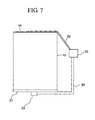
- FIG. 7 is a side view illustrating a protector attached to the battery according to an embodiment of the present invention.
-
- Reference will now be made in detail to the embodiments of the present invention, examples of which are illustrated in the accompanying drawings, wherein like reference numerals refer to the like elements throughout. The embodiments are described below to explain the present invention by referring to the figures.
- FIG. 1 is an exploded perspective view of a secondary battery according to an embodiment of the present invention. Referring to FIG. 1, the secondary battery includes a
can 10 having an opening 11 at one plane. Anelectrode unit 30 is accommodated inside thecan 10 through the opening 11. - Although not shown in detail, the
electrode unit 30 is configured such that a separator is disposed between a positive electrode plate and a negative electrode plate. According to an embodiment of the present invention, shown in FIG. 1, theelectrode unit 30 is of a jelly roll type in which a positive electrode plate, a negative electrode plate and a separator disposed therebetween are laminated and wound. However, it is understood that other types of electrode units can be used which are not jelly roll type structures. - The negative electrode plate includes a negative electrode collector made of a strip-like metal foil, and a copper foil can be used as the negative electrode collector. A negative electrode coating portion coated with a negative electrode compound material containing a negative electrode active material is formed on at least one plane of the negative electrode collector. A carbon material can be used as the negative electrode active material. The negative electrode compound material includes a binder, a plasticizer, a conductive material and the like. However, it is understood that negative electrode plates can be made with other materials and compounds.
- The positive electrode plate includes a positive electrode collector made of a strip-like metal foil, and an aluminum foil can be used as the positive electrode collector. A positive electrode coating portion coated with a positive electrode compound material containing a positive electrode active material is formed on at least one plane of the positive electrode collector. A lithium oxide can be used as the positive electrode active material. The positive electrode compound material includes a binder, a plasticizer, a conductive material and the like. However, it is understood that the positive electrode plates can be made with other materials and compounds.
- As shown in FIG. 1, a
positive electrode tab 31 and anegative electrode tab 32 are electrically connected to the corresponding positive electrode plate and the negative electrode plate and are drawn out to the upper portion of theelectrode unit 30. A nickel foil and an aluminum foil can be used as thenegative electrode tab 32 and thepositive electrode tab 31, respectively, but thetabs positive electrode tab 31 and thenegative electrode tab 32 may be opposite to those shown in FIG. 1. - As shown in FIG. 1, according to an embodiment of the present invention, the
can 10 can be made of a rectangular metal material. Accordingly, thecan 10 itself can serve as a terminal according to an aspect of the invention. According to an embodiment of the present invention, thecan 10 can be made of a light, conductive metal such as Al or an Al alloy. Thecan 10 has theopening 11 at the one plane, and theelectrode unit 30 is accommodated inside thecan 10 through theopening 11. As shown in FIG. 1, thecan 11 may be shaped of a rectangle having angled edges at its lateral sides. Also, although not shown, the edges may be round. Additional configurations can similarly be set or developed according to the intended use. - The
cap assembly 20 is sealed with theopening 11 of thecan 11. Thecap assembly 20 includes acap plate 21 directly welded with theopening 11 for sealing. Thecan 10 and thecap plate 21 may be formed of the same metal for increasing weldability. - A
terminal pin 22 is formed in thecap assembly 20 so as to penetrate thecap plate 21 via agasket 23, and an insulating plate (not shown) may be further formed under theterminal pin 22 so that theterminal pin 22 is insulated from thecap plate 21 according to an aspect of the invention. Anegative electrode tab 32 is drawn out from a negative electrode plate of theelectrode unit 30 and is welded to the lower portion of theterminal pin 22, functioning as a negative electrode terminal. Apositive electrode tab 31 is drawn out from a positive electrode plate and is directly electrically connected to the inner surface of thecan 10 so that the outer portion of the battery except theterminal pin 22 may function as a positive electrode terminal. However, structures of the positive and negative electrode terminals are not limited to those described above. That is, the positive electrode terminal may be formed using a separate terminal pin, like the negative electrode terminal, and other various structures may be employed. - After the
electrode unit 30 is inserted into thecan 10, aprotective case 26 made of an insulating material is further provided between theelectrode unit 30 and thecap assembly 20, thereby fixing theelectrode unit 30 in a more secured manner. After thecap assembly 20 is welded to theopening 11 of thecan 10, an electrolytic solution is injected into theelectrode unit 20 through aninlet 24 formed at thecap plate 21 and sealed using aplug 25 so as to form a generation element with theelectrode unit 30. However, thecase 26 need not be used in all aspects of the invention. Further, it is understood that the generation element need not use an electrolytic solution, and could instead use a solid electrolyte. Additionally, it is understood that other types of generation elements can be used to generate electrical power. - In the secondary battery according to an embodiment of the present invention, a
first surface coating 40 is provided at the outer surface of thebottom portion 12 of thecan 10 as shown in FIG. 2. The thickness (T) of thebottom portion 12 of thecan 10 is preferably in the range of 0.2 to 0.8 mm. If the thickness is greater than 0.8 mm, the volume and weight of the battery may increase. If the thickness is less than 0.2 mm, the strength of the battery may be impaired. However, it is understood that the thickness (T) can be otherwise, depending on factors such as the material of thecase 10, and that thecoating 40 can be any film or layer disposed on thecan 10. - In the shown embodiment of the present invention, the
first surface coating 40 is provided for the purpose of increasing weldability between a lead of a safety device of the battery and thebottom portion 12. Preferably, thefirst surface coating 40 can be made of nickel or a nickel alloy having nickel as a main component. However, other material can be used, and thecoating 40 can have other purposes in addition to or instead of improving weldability. - According to an aspect of the invention, the composition of the nickel and a nickel alloy in the
coating 40 may be the same as that of a conventional nickel plate such as that shown in U.S. Patent No. 5,976,729 welded to acan 10 made of aluminum, the disclosure of which is incorporated herein by reference. Additionally, according to an aspect of the invention, phosphorus (P), boron (B) or tungsten (W) may be further added thereto in order to obtain desired properties including corrosion resistance. - As shown in the embodiment of the invention shown in FIG. 3, a
first metal layer 39 is further disposed between the outer surface of thebottom portion 12 and thefirst surface coating 40. Materials of thefirst metal layer 39 are different from those of thecan 10 and thefirst surface coating 40. Examples of thefirst metal layer 39 include Zn, Sn, Fe, Cr and so on. Thefirst metal layer 39 may be formed on the outer surface of thebottom portion 12 by pre-treatment before formation of thefirst surface coating 40 according to an aspect of the invention. In such a manner, oxidation can be prevented by adjusting an oxidation-reduction level, and an area for reaction between thebottom portion 12 and thefirst surface coating 40. Adhesion between thebottom portion 12 and thefirst surface coating 40 can also be increased. Further, surface tension can be increased and thefirst surface coating 40 can be made uniform. Also, a plating energy required for forming thefirst surface coating 40 by plating can be reduced and surface irregularities and damages of thebottom portion 12 can be avoided. - According to an aspect of the invention, the
first surface coating 40 made of nickel can be formed by a general electrolytic plating method. In electrolytic plating, an oxidation film formed on the surface of thecan 10 made of aluminum is first removed by pickling in which the oxidation film is immersed in an acid solution of pH 2 or less. Ni or a Ni alloy is then plated on the surface of thecan 10 by immersing the can in a Ni plating bath or a Ni alloy plating bath and by applying current to the bath. Here, thecan 10 may be entirely plated, which may, however, increase the overall weight and volume of thecan 10. Thus, it is generally preferred that only thebottom portion 12 of thecan 10 is plated. To this end, portions other than thebottom portion 12 of thecan 10 are preferably screened by an insulating material so as to expose only thebottom portion 12. Thefirst surface coating 40 may be formed only partially at an outer portion of thebottom portion 12 or entirely at the outer portion of thebottom portion 12. The area in which thefirst surface coating 40 is formed can be adjusted by adjusting the exposed area of thebottom portion 12 when the screening is performed prior to plating. - According to an aspect of the invention, the
first surface coating 40 made of nickel may be formed by general electroless plating. Any electroless plating method that can form a nickel-based plating layer on the surface of acan 10 made of aluminum may be applied in forming thefirst surface coating 40. However, in an embodiment of the present invention, thefirst surface coating 40 is subjected to zincate pre-treatment in a state in which thecan 10 except thebottom portion 12 is screened, and electroless plating of nickel is then performed. The zincate pre-treatment is performed for the purpose of preventing a reduction of aluminum plating reactivity and adhesiveness. That is, a zinc nucleus is formed at thebottom portion 12 using a potential difference between the aluminum can 10 screened except thebottom portion 12 and zinc contained in a zincate solution. - For example, where the
can 10 is screened except thebottom portion 12, the surface of thecan 10 is degreased using a degreasing solution containing sodium hydroxide (NaOH) and then etched using an etching solution containing sodium carbonate (Na2CO3) and sodium phosphate (Na3PO4), thereby removing the oxidation film from the surface of thecan 10. The can 10 from which the oxidation film is removed is activated in an activating solution containing nitric acid and is then subjected to zincate treatment in a zincate solution containing zinc oxide (ZnO), sodium hydroxide (NaOH), iron dichloride (FeCl3), or Rochelle salt such as potassium sodium tartrate (KNaC4H4O6·4H2O), thereby forming a zinc coating. An electroless nickel plating reaction is initiated at the zinc nucleus formed by the zincate treatment. The zincate pre-treatment can also be applied to the electrolytic plating, and thefirst metal layer 39 shown in FIG. 3 is formed by the pre-treatment. - The
first surface coating 40 can be formed only partially or entirely at thebottom portion 12, and the area thereof can be adjusted by adjusting the exposed area of thebottom portion 12. Alternatively, the nickel-based,first surface coating 40 can be formed directly on at least thebottom portion 12 of thecan 10 by sputtering. The sputtering of nickel can be any general sputtering method. - According to another embodiment of the present invention, the
first surface coating 40 can be made of copper or a copper alloy containing copper as a main component. The copper-basedfirst surface coating 40 can also be formed by electrolytic plating or electroless plating. It is preferred, but not required, that an oxidation film is removed from the surface of thecan 10 prior to plating and a zinc nucleus is created by zincate pre-treatment. Any electrolytic plating or electroless plating can be used for plating of the copper-based,first surface coating 40. The copper-based,first surface coating 40 can also be formed by directly sputtering copper, or in the form of a clad layer. - Specifically and by way of example, an insert material made of pure aluminum is cold-rolled to a copper member (i.e., the first surface coating 40) for adhesion, and the insert material is applied to the
bottom portion 12 of thecan 10 and adhered by hot pressing. The insert material employing highly pure aluminum allows adhesion with the copper member and thecan 10 to be improved. - The thickness (T) of the
first surface coating 40 can vary in consideration of the overall height of the battery and the strength of a coating. According to an embodiment of the present invention, thefirst surface coating 40 may be 0.5 µm to 200 µm in thickness, and preferably between 30 µm to 100 µm. If the thickness of thefirst surface coating 40 is less than 0.5 µm, uniformity in plating thickness cannot be ensured and imperfect plating (for example, local failure in plating or exfoliation) may occur. If the thickness of thefirst surface coating 40 is greater than 200 µm, the plating layer becomes overly thick, making it difficult to obtain a spacious internal space of thecan 10. When the thickness (T) of thefirst surface coating 40 is in the range of 30 µm to 100 µm, an appropriate welding strength can be ensured even by welding of a lead 50 (shown in FIG. 5) and an increase in the weight and volume of the battery can also be suppressed. - Therefore, forming the
first surface coating 40 can noticeably reduce the thickness of abottom portion 12 of thecan 10 compared to the conventional batteries, where a nickel plate is adhered to the can by welding. Thus, a design margin of a battery pack can be ensured using the present invention. Also, leakage of an electrolytic solution can be prevented during welding using the present invention. - After forming the
first surface coating 40, alead 50 is welded to thefirst surface coating 40 as shown in FIG. 4. As shown in FIG. 7, thelead 50 is connected to asafety device 70 mounted on a battery. Examples ofsuch safety devices 70 include, but are not limited to, a positive temperature coefficient (PTC) element or a protector, and can be made of nickel, a nickel alloy, aluminum or an aluminum alloy. Asecond lead 80 connects the terminal 22 and thesafety device 70. - When the
first surface coating 40 is made of nickel or a nickel alloy, thelead 50 can be made to adhere to thecoating 40 by welding according to an aspect of the invention. For instance, the welding can be specifically resistance welding, which is the simplest welding method. In addition, ultrasonic welding or laser welding can be employed. Further, adhesion by soldering can also be employed. Thus, unlike in the conventional plate welding, problems of an increase in welding facility due to double welding, leakage of an electrolytic solution and poor reliability of a safety device, can be overcome. - The
first surface coating 40 can be made of various materials in addition to the nickel-or copper-based materials according to an aspect of the invention. Specifically, the materials of thefirst surface coating 40 can be determined by a difference in the melting point between materials of thefirst surface coating 40 and thelead 50. In other words, resistance welding is the simplest method of adhering thelead 50 to thefirst surface coating 40 with a high strength, and, for attaining a higher welding strength, a difference in the melting point between materials of thelead 50 and thefirst surface coating 40 is at or less than 500 °C, and preferably at or less than 200 °C. Thus, any material having a melting point difference of 500 °C or less (and preferably 200 °C or less) from that of thelead 50 can be used in forming thefirst surface coating 40. - In accordance with another embodiment of the present invention, as shown in FIG. 5, a
second surface coating 41 is formed on at least an outer surface of thecap plate 21. In the shown embodiment of the present invention, thesecond surface coating 41 prevents contamination of a probe of an initial charging/discharging device. While not required, it is preferred that, thesecond surface coating 41 is made of the same material and by the same method with thefirst surface coating 40. For example, the second surface coating 41 can be made of nickel, a nickel alloy, copper or a copper alloy. In the shown embodiment, the thickness of thecap plate 21 may be in the range of 0.2 mm to 0.8 mm, similar to the thickness of thebottom portion 12 of thecan 10. However, it is understood that the thickness need not be in the range of thebottom portion 12 of thecan 10, and that thecoatings 41, 51 can be any film or layer disposed on thecan 10. - Where the
second surface coating 41 is made of nickel or a nickel alloy, a plating layer may be formed thereon by electrolytic plating or electroless plating according to an aspect of the invention. Also, the second surface coating 41 can be formed directly by deposition, such as by sputtering, according to an aspect of the invention. - Where the
second surface coating 41 is made of copper or a copper alloy, a clad layer can be formed thereon by a cladding method. In this case, as shown in the embodiment of the invention in FIG. 6, asecond metal layer 43 may be further provided between thesecond surface coating 41 and thecap plate 21. Materials of thesecond metal layer 43 are different from those of thecap plate 21 and the second surface coating 41 according to an aspect of the invention. Examples of themetal layer 43 include, but are not limited to, Zn, Sn, Fe, Cr and so on. Thesecond metal layer 43 may be formed on the outer surface of thecap plate 21 by pre-treatment before formation of the second surface coating 41 according to an aspect of the invention. In such a manner, the same or similar effects as those when forming thefirst metal layer 39 on thebottom portion 12 can be achieved. - The second surface coating 41 can also be 0.5 µm to 200 µm in thickness, and preferably 30 µm to 100 µm according to aspects of the invention. If the thickness of the
second surface coating 41 is less than 0.5 µm, uniformity in plating thickness cannot be ensured and there may occur imperfect plating (for example, local failure in plating or exfoliation). If the thickness of thefirst surface coating 40 is greater than 200 µm, the plating layer becomes overly thick, making it difficult to obtain a spacious internal space of thecan 10. When the thickness of thesecond surface coating 41 is in the range of 30 µm to 100 µm, an appropriate welding strength can be ensured even and an increase in the weight and volume of the battery can also be suppressed. However, it is understood that other thickness can be used. - The second surface coating 41 can be advantageously used for the purpose of supporting the
terminal pin 22 and thecap plate 21, which is not the case where the probe (Not shown) of the initial charging and discharging device supports theterminal pin 22 and thebottom portion 12. That is, thesecond surface coating 41 prevents a leading edge of the probe from being contaminated by a material of the cap plate 21 (i.e., aluminum), thereby preventing inaccuracy in voltage measurement. Also, since thelead 80 connected with thesafety device 70 of the battery is directly drawn out from thecap plate 21 as shown in FIGs. 5-7, a voltage drop due to elongation of the 50 lead can be suppressed. Here, thelead 80 connected to thesafety device 70 can be adhered by welding, specifically resistance welding, in the case where thesecond surface coating 41 is made of nickel. Also, ultrasonic welding, laser welding or soldering can be employed. Thus, unlike in the conventional plate welding, various problems due to double welding can be overcome. - In connecting the
lead 80 of thesafety device 70 to thesecond surface coating 41, like in thefirst surface coating 40, the second surface coating 41 can be made of a material having a melting point difference of 500 °C or less (preferably 200 °C or less) from a material of thelead 80 welded thereto. - The secondary battery according to aspects of the present invention has the following and/or other effects. Since it is not necessary to weld a bottom plate to a bottom surface of a can of the battery according to an aspect of the invention, adhesion of a lead can be achieved in a simplified manner. Also, since welding of a bottom plate is not performed according to an aspect of the invention, thermal deformation of a safety vent can be prevented when the safety vent is installed on the bottom portion of the can. Further, formation of a surface coating simplifies adhesion of a lead connected to a safety device of the battery, ensuring reliability of the safety device according to an aspect of the invention. Additionally, since a thin surface coating serves as a plate according to an aspect of the invention, the overall height of the battery can be reduced and a battery capacity can be increased accordingly. Moreover, contamination of a leading edge of a probe for initially charging and discharging the battery can be prevented according to an aspect of the invention.
- While a few embodiments of the present invention have been particularly shown and described with reference to embodiments thereof, it will be understood by those skilled in the art that various changes in form and details may be made therein without departing from the spirit and scope of the invention as defined by the appended claims and their equivalents.
Claims (66)
- A secondary battery comprising:an electrode unit having a positive electrode plate, a negative electrode plate and a separator disposed therebetween;a can having a bottom portion and in which the electrode unit and an electrolytic solution are accommodated and sealed, the can comprising aluminum or an aluminum alloy; anda layer provided on at least an outer surface of the bottom portion of the can.
- The secondary battery of claim 1, wherein the layer has at least nickel as a main component.
- The secondary battery of claim 2, wherein the layer is formed by at least one method selected from the group consisting of electrolytic plating, electroless plating and sputtering.
- The secondary battery of claim 1, wherein the layer has at least copper as a main component.
- The secondary battery of claim 4, wherein the layer is formed by at least one method selected from the group consisting of electrolytic plating, electroless plating, sputtering and cladding.
- The secondary battery of claim 1, further comprising a safety device and a lead unit which connects the positive and negative electrode plates through the safety device, the lead unit comprising a lead electrically connected to the safety device and which is welded to the layer.
- The secondary battery of claim 6, wherein the lead is welded to the layer by resistance welding.
- The secondary battery of claim 7, wherein the layer comprises a first material, the lead comprises a second material other than the first material, and a melting point difference between the first and second materials is 500 °C or less.
- The secondary battery of claim 8, wherein a melting point difference between the first and second materials is 200 °C or less.
- The secondary battery of claim 4, further comprising a safety device and a lead unit which electrically connects the positive and negative electrode plates through the safety device, the lead unit comprising a lead electrically connected to the safety device and which is adhered to the layer by soldering.
- The secondary battery of claim 1, wherein the layer has a thickness of 0.5 µm to 200 µm.
- The secondary battery of claim 11, wherein the layer has a thickness of 30 µm to 100 µm.
- The secondary battery of claim 1, further comprising a metal layer between the layer and the outer surface of the bottom portion of the can, wherein the metal layer comprises a first material, the can comprises a second material including the aluminum or the aluminum alloy, the layer comprises the second material, and the second material is different from the first material.
- The secondary battery of claim 13, wherein the first material of the metal layer comprises at least one material selected from the group consisting of Zn, Sn, Fe and Cr.
- The secondary battery of claim 1, wherein a thickness of the bottom portion of the can is in the range of 0.2 mm to 0.8 mm.
- The secondary battery of claim 1, wherein the layer is formed partially or entirely at the outer surface of the can.
- A secondary battery comprising:an electrode unit having a positive electrode plate, a negative electrode plate and a separator disposed therebetween;a can having a bottom portion and in which the electrode unit and an electrolytic solution are accommodated and sealed, the can comprising aluminum or an aluminum alloy;a cap assembly sealing an opening of the can and having a cap plate insulated from the positive and negative electrode plates of the electrode unit, the cap plate comprising aluminum or an aluminum alloy; anda layer provided on at least an outer surface of the cap plate.
- The secondary battery of claim 17, wherein the layer comprises at least nickel as a main component.
- The secondary battery of claim 18, wherein the layer is formed by at least one method selected from the group consisting of electrolytic plating, electroless plating and sputtering.
- The secondary battery of claim 17, wherein the layer comprises at least copper as a main component.
- The secondary battery of claim 20, wherein the layer is formed by at least one method selected from the group consisting of electrolytic plating, electroless plating, sputtering and cladding.
- The secondary battery of claim 17, further comprising a safety device and a lead unit which electrically connects the positive and negative electrode plates through the safety device, the lead unit comprising a lead electrically connected to the safety device and is welded to the layer.
- The secondary battery of claim 22, wherein the lead is welded to the layer by resistance welding.
- The secondary battery of claim 23, wherein the layer comprises a first material, the lead comprises a second material other than the first material, and a melting point difference between the first and second materials is 500 °C or less.
- The secondary battery of claim 24, wherein a melting point difference between the first and second materials is 200 °C or less.
- The secondary battery of claim 20, further comprising a safety device and a lead unit which electrically connects the positive and negative electrode plates through the safety device, the lead unit comprising a lead electrically connected to the safety device and is adhered to the layer by soldering.
- The secondary battery of claim 17, wherein the layer has a thickness of 0.5 µm to 200 µm.
- The secondary battery of claim 27, wherein the layer has a thickness of 30 µm to 100 µm.
- The secondary battery of claim 17, further comprising a metal layer between the layer and the outer surface of the cap plate, wherein the metal layer comprises a first material, the cap plate comprises a second material including the aluminum or the aluminum alloy, the layer comprises the second material, and the second material is other than the first material.
- The secondary battery of claim 29, wherein the first material of the metal layer is made of at least one material selected from the group consisting of Zn, Sn, Fe and Cr.
- The secondary battery of claim 17, wherein a thickness of the cap plate is in the range of 0.2 mm to 0.8 mm.
- The secondary battery of claim 17, wherein the layer is formed partially or entirely at the outer surface of the cap plate.
- A method of manufacturing a secondary battery comprising:forming an electrode unit by providing a positive electrode plate and a negative electrode plate and interposing a separator therebetween;accommodating the electrode unit and an electrolytic solution inside a can having a bottom portion and sealing the can, the can comprising a first material;forming a metal layer of a second material other than the first material on an outer surface of the bottom portion of the can by pre-treatment; andforming a surface coating on the outer surface of the bottom portion of the can having the first metal layer.
- The method of claim 33, further comprising screening portions other than the outer surface of the bottom portion of the can where the metal layer is formed before performing the pre-treatment.
- The method of claim 33, wherein the forming of the surface coating is performed by at least one method selected from the group consisting of electrolytic plating, electroless plating, sputtering and cladding.
- A method of manufacturing a secondary battery comprising:forming an electrode unit by providing a positive electrode plate and a negative electrode plate and interposing a separator therebetween;accommodating the electrode unit and an electrolytic solution inside a can having a bottom portion;sealing the can with a cap plate insulated from either electrode of the electrode unit, the cap plate comprising a first material;forming a metal layer of a second material other than the first material on an outer surface of the cap plate by pre-treatment; andforming a surface coating on the outer surface of the cap plate having the second metal layer.
- The method of claim 36, further comprising screening portions other than the outer surface of the bottom portion of the can where the metal layer is formed before performing the pre-treatment.
- The method of claim 36, wherein the forming of the surface coating is performed by at least one method selected from the group consisting of electrolytic plating, electroless plating, sputtering and cladding.
- A battery comprising:a generation element which generates electrical power;a can having a surface made of a first material and which houses the generation element, a first terminal electrically connected to the generation element and a second terminal disposed at the surface and which is electrically connected to the generation element; anda layer provided on the surface and comprising a second material other than the first material, the second material comprising at least nickel as a main component.
- The battery of claim 39, further comprising a safety device and a lead unit which electrically connects the first terminal and the second terminal through the safety device and having a lead with one end disposed at the surface and another end disposed at the safety device.
- The battery of claim 40, wherein the lead is welded to the layer by resistance welding.
- The battery of claim 40, wherein:the lead comprises a third material; anda melting point difference between the second material and the third material is 500 °C or less.
- The battery of claim 42, wherein the melting point difference between the second and third materials is 200 °C or less.
- The battery of claim 41, wherein the lead is connected to the layer by soldering.
- The battery of claim 39, wherein the layer has a thickness of 0.5 µm to 200 µm.
- The battery of claim 45, wherein the layer has a thickness of 30 µm to 100 µm.
- The battery of claim 39, further comprising a metal layer between the layer and the surface, wherein the metal layer comprises a third material other than the first and second materials.
- The battery of claim 47, wherein the third material comprises at least one material selected from the group consisting of Zn, Sn, Fe and Cr.
- The battery of claim 39, wherein the can comprises side surfaces connected to the surface at corresponding boundaries, and the layer extends entirely between the boundaries on the surface.
- The battery of claim 39, wherein the can comprises side surfaces connected to the surface at corresponding boundaries, and the layer extends between the boundaries on the surface such that the layer does not cover a portion of the surface.
- The battery of claim 39, wherein a thickness of the surface is in a range of 0.2 mm to 0.8 mm.
- The battery of claim 39, wherein the can comprises a cap plate sealing an opening in the can through which the generation element is disposed in the can, and the surface is not on the cap plate.
- The battery of claim 39, wherein the can comprises a cap plate sealing an opening in the can through which the generation element is disposed in the can, and the cap plate includes the surface.
- The battery of claim 42, wherein the can comprises a cap plate sealing an opening in the can through which the generation element is disposed in the can, and the cap plate includes the surface.
- The battery of claim 47, wherein the can comprises a cap plate sealing an opening in the can through which the generation element is disposed in the can, and the cap plate includes the surface.
- The battery of claim 39, wherein the layer is formed by coating the second material on the surface.
- The battery of claim 56, wherein the layer is formed by at least one method selected from the group consisting of electrolytic plating, electroless plating and sputtering.
- The battery of claim 39, wherein the first material comprises at least aluminum as a main component.
- A method of manufacturing a secondary battery, comprising:wherein the safety device is electrically connected between positive and negative terminals of the generation element using a lead unit including the lead.coating a layer on a surface of a can of the secondary battery, the layer comprising a second material other than a first material of the can, and the can housing a generation element which generates electrical power; andattaching a lead to the coated layer, the lead being connected to a safety device of the battery,
- The method of 59, further comprising disposing another layer of a third material other than the first and second materials prior to coating the layer on the surface of the can, wherein the coating the layer on the surface of the can comprises coating the layer on the another layer.
- The method of claim 59, wherein the can comprises a cap plate comprising the surface and sealing an opening in the can through which the generation element is disposed in the can, and the coating the layer comprises coating the layer on the cap plate.
- The method of claim 59, wherein the can comprises a cap plate sealing an opening in the can through which the generation element is disposed in the can, and the coating the layer comprises coating the layer on the surface not on the cap plate.
- The method of claim 59, wherein the coating the layer comprising coating the layer using an electroless plating method.
- The method of claim 59, wherein the coating the layer comprising coating the layer using an electrolytic plating method.
- The method of claim 59, wherein the coating the layer comprising coating the layer using a sputtering method.
- The method of claim 59, wherein the coating the layer comprising coating the layer using a cladding method.
Applications Claiming Priority (4)
| Application Number | Priority Date | Filing Date | Title |
|---|---|---|---|
| KR2002085434 | 2002-12-27 | ||
| KR10-2002-0085434A KR100502338B1 (en) | 2002-12-27 | 2002-12-27 | Secondary battery |
| KR1020030058268A KR100542197B1 (en) | 2003-08-22 | 2003-08-22 | Secondary battery |
| KR2003058268 | 2003-08-22 |
Publications (2)
| Publication Number | Publication Date |
|---|---|
| EP1453123A1 true EP1453123A1 (en) | 2004-09-01 |
| EP1453123B1 EP1453123B1 (en) | 2017-02-15 |
Family
ID=32716453
Family Applications (1)
| Application Number | Title | Priority Date | Filing Date |
|---|---|---|---|
| EP03090453.6A Expired - Lifetime EP1453123B1 (en) | 2002-12-27 | 2003-12-22 | Secondary battery and manufacturing method thereof |
Country Status (4)
| Country | Link |
|---|---|
| US (1) | US8334066B2 (en) |
| EP (1) | EP1453123B1 (en) |
| JP (1) | JP4184927B2 (en) |
| CN (1) | CN100352098C (en) |
Families Citing this family (27)
| Publication number | Priority date | Publication date | Assignee | Title |
|---|---|---|---|---|
| JP2005203367A (en) * | 2004-01-13 | 2005-07-28 | Samsung Sdi Co Ltd | Secondary battery |
| JP4342494B2 (en) * | 2004-09-24 | 2009-10-14 | 三星エスディアイ株式会社 | Lithium secondary battery |
| KR100571272B1 (en) * | 2004-11-18 | 2006-04-13 | 삼성에스디아이 주식회사 | Can-type secondary battery and its formation method |
| JP5053510B2 (en) * | 2004-12-27 | 2012-10-17 | 冨士発條株式会社 | Power supply device outer can and power supply device using the outer can |
| KR100646520B1 (en) * | 2005-03-09 | 2006-11-14 | 삼성에스디아이 주식회사 | Secondary Battery and Its Assembly Method |
| KR100646529B1 (en) | 2005-03-24 | 2006-11-23 | 삼성에스디아이 주식회사 | Lithium secondary battery |
| KR100821857B1 (en) * | 2006-10-23 | 2008-04-15 | 주식회사 엘지화학 | Rechargeable battery pack |
| TWD127614S1 (en) * | 2007-10-17 | 2009-03-01 | 電盛蘭達股份有限公司 | The battery pack used for uninterruptible power supply |
| WO2009064661A1 (en) * | 2007-11-15 | 2009-05-22 | Nitto Denko Corporation | Light emitting devices and compositions |
| US8703327B2 (en) | 2008-06-20 | 2014-04-22 | Samsung Sdi Co., Ltd. | Rechargeable battery and manufacturing method thereof |
| KR101049832B1 (en) * | 2009-06-04 | 2011-07-15 | 에스비리모티브 주식회사 | Secondary battery |
| DE102009049890A1 (en) * | 2009-10-20 | 2011-04-21 | H & T Marsberg Gmbh & Co. Kg | Galvanic element as a device battery |
| KR20110048774A (en) * | 2009-11-03 | 2011-05-12 | 삼성에스디아이 주식회사 | Cap assembly and secondary battery having the same |
| JP2012013035A (en) * | 2010-07-02 | 2012-01-19 | Daikin Industries Ltd | Air blowing device |
| CN102560483A (en) * | 2010-12-30 | 2012-07-11 | 鸿富锦精密工业(深圳)有限公司 | Aluminium and aluminium alloy surface antiseptic treatment method and product prepared by same |
| EP3782966A1 (en) * | 2011-02-18 | 2021-02-24 | Schott AG | Feedthrough |
| KR20140091029A (en) | 2011-10-31 | 2014-07-18 | 티코나 엘엘씨 | Thermoplastic composition for use in forming a laser direct structured substrate |
| WO2013066683A2 (en) * | 2011-11-03 | 2013-05-10 | Johnson Controls Technology Llc | Prismatic lithium ion cell with positive polarity rigid container |
| CN110224087A (en) * | 2011-11-03 | 2019-09-10 | Cps科技控股有限公司 | Prismatic lithium ion battery cell with positive polarity rigid container |
| KR101433666B1 (en) * | 2012-02-07 | 2014-08-25 | 주식회사 엘지화학 | Method for Battery Cell Having Uncoated Part of Battery Case |
| KR101365968B1 (en) * | 2012-02-07 | 2014-02-24 | 주식회사 엘지화학 | Method for Battery Cell of Novel Structure |
| DE102012218991A1 (en) | 2012-10-18 | 2014-06-12 | Bayerische Motoren Werke Aktiengesellschaft | Energy storage cell and energy storage module |
| KR20140065950A (en) * | 2012-11-22 | 2014-05-30 | 삼성에스디아이 주식회사 | Rechargeable battery |
| EP3711103A1 (en) * | 2017-11-14 | 2020-09-23 | VARTA Microbattery GmbH | Thin, secondary miniature cell having a metal housing closed by means of a plastic cover, and method for producing said miniature cell |
| DE102018219433A1 (en) * | 2018-11-14 | 2020-05-14 | Robert Bosch Gmbh | Electrical energy storage cell, electrical energy storage and device |
| KR102522106B1 (en) | 2019-06-10 | 2023-04-14 | 주식회사 엘지에너지솔루션 | Cylindrical Secondary Battery with Multilayered Battery Case And Method of Manufacturing The Same |
| CN113721152B (en) * | 2021-08-13 | 2024-04-19 | 宁德新能先锋检测科技有限公司 | Detection system based on lithium battery test pretreatment |
Citations (12)
| Publication number | Priority date | Publication date | Assignee | Title |
|---|---|---|---|---|
| JPS60124351A (en) * | 1983-12-07 | 1985-07-03 | Matsushita Electric Ind Co Ltd | Nonaqueous electrolyte cell |
| JPH0256849A (en) * | 1988-08-23 | 1990-02-26 | Matsushita Electric Ind Co Ltd | organic electrolyte battery |
| JPH08329908A (en) * | 1995-06-02 | 1996-12-13 | Sanyo Electric Co Ltd | Aluminum outer can secondary battery |
| EP0798794A1 (en) * | 1996-03-27 | 1997-10-01 | SANYO ELECTRIC Co., Ltd. | A cell which secures the reliability of a protective circuit |
| EP0827230A2 (en) * | 1996-09-03 | 1998-03-04 | Fuji Photo Film Co., Ltd. | Non-aqueous lithium ion secondary battery |
| EP0899799A2 (en) * | 1997-08-29 | 1999-03-03 | Sumitomo Electric Industries, Ltd. | Jar can for secondary battery |
| EP0944119A1 (en) * | 1997-09-08 | 1999-09-22 | Matsushita Electric Industrial Co., Ltd. | Battery and method of manufacturing the same |
| EP0959508A1 (en) * | 1998-05-22 | 1999-11-24 | Texas Instruments Incorporated | Current interrupt apparatus particularly adapted for use with prismatic electrochemical cells |
| WO2002003483A1 (en) * | 2000-06-29 | 2002-01-10 | Quallion Llc | Battery case feedthrough |
| US20020142195A1 (en) * | 2001-03-30 | 2002-10-03 | Yukio Ehara | Battery pack |
| JP2003157904A (en) * | 2001-11-22 | 2003-05-30 | Gs-Melcotec Co Ltd | Lithium ion battery and battery device |
| JP2003257411A (en) * | 2002-03-04 | 2003-09-12 | Matsushita Electric Ind Co Ltd | Non-aqueous electrolyte battery |
Family Cites Families (9)
| Publication number | Priority date | Publication date | Assignee | Title |
|---|---|---|---|---|
| JPH04184861A (en) * | 1990-11-16 | 1992-07-01 | Fuji Elelctrochem Co Ltd | Lithium battery manufacturing method |
| JPH1021889A (en) * | 1996-06-27 | 1998-01-23 | Toyota Central Res & Dev Lab Inc | Lithium ion secondary battery container and electrode current collector |
| JP3857818B2 (en) * | 1997-09-08 | 2006-12-13 | 松下電器産業株式会社 | Lithium ion secondary battery |
| JP4056147B2 (en) * | 1997-09-30 | 2008-03-05 | 松下電器産業株式会社 | battery |
| JPH11265692A (en) | 1998-03-18 | 1999-09-28 | Toshiba Battery Co Ltd | Battery case |
| JP4437302B2 (en) | 1998-08-13 | 2010-03-24 | 東芝電池株式会社 | Battery container |
| CN1172400C (en) * | 1999-08-10 | 2004-10-20 | 三洋电机株式会社 | Nonaqueous electrolyte secondary battery and method for manufacturing same |
| US6830847B2 (en) * | 2001-04-10 | 2004-12-14 | The Gillette Company | Zinc/air cell |
| US6869727B2 (en) * | 2002-09-20 | 2005-03-22 | Eveready Battery Company, Inc. | Battery with high electrode interfacial surface area |
-
2003
- 2003-11-11 JP JP2003381814A patent/JP4184927B2/en not_active Expired - Lifetime
- 2003-12-22 EP EP03090453.6A patent/EP1453123B1/en not_active Expired - Lifetime
- 2003-12-24 US US10/743,866 patent/US8334066B2/en active Active
- 2003-12-26 CN CNB2003101235519A patent/CN100352098C/en not_active Expired - Lifetime
Patent Citations (12)
| Publication number | Priority date | Publication date | Assignee | Title |
|---|---|---|---|---|
| JPS60124351A (en) * | 1983-12-07 | 1985-07-03 | Matsushita Electric Ind Co Ltd | Nonaqueous electrolyte cell |
| JPH0256849A (en) * | 1988-08-23 | 1990-02-26 | Matsushita Electric Ind Co Ltd | organic electrolyte battery |
| JPH08329908A (en) * | 1995-06-02 | 1996-12-13 | Sanyo Electric Co Ltd | Aluminum outer can secondary battery |
| EP0798794A1 (en) * | 1996-03-27 | 1997-10-01 | SANYO ELECTRIC Co., Ltd. | A cell which secures the reliability of a protective circuit |
| EP0827230A2 (en) * | 1996-09-03 | 1998-03-04 | Fuji Photo Film Co., Ltd. | Non-aqueous lithium ion secondary battery |
| EP0899799A2 (en) * | 1997-08-29 | 1999-03-03 | Sumitomo Electric Industries, Ltd. | Jar can for secondary battery |
| EP0944119A1 (en) * | 1997-09-08 | 1999-09-22 | Matsushita Electric Industrial Co., Ltd. | Battery and method of manufacturing the same |
| EP0959508A1 (en) * | 1998-05-22 | 1999-11-24 | Texas Instruments Incorporated | Current interrupt apparatus particularly adapted for use with prismatic electrochemical cells |
| WO2002003483A1 (en) * | 2000-06-29 | 2002-01-10 | Quallion Llc | Battery case feedthrough |
| US20020142195A1 (en) * | 2001-03-30 | 2002-10-03 | Yukio Ehara | Battery pack |
| JP2003157904A (en) * | 2001-11-22 | 2003-05-30 | Gs-Melcotec Co Ltd | Lithium ion battery and battery device |
| JP2003257411A (en) * | 2002-03-04 | 2003-09-12 | Matsushita Electric Ind Co Ltd | Non-aqueous electrolyte battery |
Non-Patent Citations (5)
| Title |
|---|
| PATENT ABSTRACTS OF JAPAN vol. 009, no. 280 (E - 356) 8 November 1985 (1985-11-08) * |
| PATENT ABSTRACTS OF JAPAN vol. 0142, no. 22 (E - 0926) 10 May 1990 (1990-05-10) * |
| PATENT ABSTRACTS OF JAPAN vol. 1997, no. 04 30 April 1997 (1997-04-30) * |
| PATENT ABSTRACTS OF JAPAN vol. 2003, no. 09 3 September 2003 (2003-09-03) * |
| PATENT ABSTRACTS OF JAPAN vol. 2003, no. 12 5 December 2003 (2003-12-05) * |
Also Published As
| Publication number | Publication date |
|---|---|
| US20040137322A1 (en) | 2004-07-15 |
| US8334066B2 (en) | 2012-12-18 |
| EP1453123B1 (en) | 2017-02-15 |
| JP2004214175A (en) | 2004-07-29 |
| JP4184927B2 (en) | 2008-11-19 |
| CN1512617A (en) | 2004-07-14 |
| CN100352098C (en) | 2007-11-28 |
Similar Documents
| Publication | Publication Date | Title |
|---|---|---|
| US8334066B2 (en) | Secondary battery and manufacturing method thereof | |
| US7781092B2 (en) | Secondary battery and method of manufacturing same | |
| KR100544119B1 (en) | Pouch Type Lithium Secondary Battery | |
| US7611797B2 (en) | Lithium secondary battery with safety device | |
| CN100440602C (en) | Cylindrical lithium rechargeable battery and manufacturing method thereof | |
| US20040126650A1 (en) | Electrode assembly for lithium ion cell and lithium cell using the same | |
| US8822069B2 (en) | Battery pack | |
| US20040228061A1 (en) | Protector and lithium secondary battery having the same | |
| US20090068548A1 (en) | Lithium Ion Prismatic Cells | |
| KR100599793B1 (en) | Secondary Battery and Electrode Assembly Used in the Same | |
| JP4749130B2 (en) | Secondary battery and method for forming the same | |
| KR101433666B1 (en) | Method for Battery Cell Having Uncoated Part of Battery Case | |
| US20050238951A1 (en) | Secondary battery | |
| JP4499648B2 (en) | Lithium ion secondary battery | |
| KR20180041019A (en) | Cylindrical Secondary Battery Having Protrusion of Improved Weld-ability | |
| KR101365968B1 (en) | Method for Battery Cell of Novel Structure | |
| KR100502338B1 (en) | Secondary battery | |
| CN116982213A (en) | Button battery with terminals | |
| KR100542197B1 (en) | Secondary battery | |
| KR100670502B1 (en) | Secondary battery | |
| JP2003257411A (en) | Non-aqueous electrolyte battery | |
| EP4685939A1 (en) | Battery cell | |
| KR100457627B1 (en) | Secondary battery with non-weldindg type bottom plate | |
| KR102472458B1 (en) | Lead tab jig | |
| KR100953542B1 (en) | Secondary battery |
Legal Events
| Date | Code | Title | Description |
|---|---|---|---|
| PUAI | Public reference made under article 153(3) epc to a published international application that has entered the european phase |
Free format text: ORIGINAL CODE: 0009012 |
|
| AK | Designated contracting states |
Kind code of ref document: A1 Designated state(s): AT BE BG CH CY CZ DE DK EE ES FI FR GB GR HU IE IT LI LU MC NL PT RO SE SI SK TR |
|
| AX | Request for extension of the european patent |
Extension state: AL LT LV MK |
|
| 17P | Request for examination filed |
Effective date: 20050207 |
|
| AKX | Designation fees paid |
Designated state(s): AT BE BG CH CY CZ DE DK EE ES FI FR GB GR HU IE IT LI LU MC NL PT RO SE SI SK TR |
|
| 17Q | First examination report despatched |
Effective date: 20100217 |
|
| GRAP | Despatch of communication of intention to grant a patent |
Free format text: ORIGINAL CODE: EPIDOSNIGR1 |
|
| INTG | Intention to grant announced |
Effective date: 20160902 |
|
| STAA | Information on the status of an ep patent application or granted ep patent |
Free format text: STATUS: GRANT OF PATENT IS INTENDED |
|
| GRAS | Grant fee paid |
Free format text: ORIGINAL CODE: EPIDOSNIGR3 |
|
| GRAA | (expected) grant |
Free format text: ORIGINAL CODE: 0009210 |
|
| STAA | Information on the status of an ep patent application or granted ep patent |
Free format text: STATUS: THE PATENT HAS BEEN GRANTED |
|
| AK | Designated contracting states |
Kind code of ref document: B1 Designated state(s): AT BE BG CH CY CZ DE DK EE ES FI FR GB GR HU IE IT LI LU MC NL PT RO SE SI SK TR |
|
| REG | Reference to a national code |
Ref country code: CH Ref legal event code: EP Ref country code: GB Ref legal event code: FG4D |
|
| REG | Reference to a national code |
Ref country code: IE Ref legal event code: FG4D |
|
| REG | Reference to a national code |
Ref country code: AT Ref legal event code: REF Ref document number: 868343 Country of ref document: AT Kind code of ref document: T Effective date: 20170315 |
|
| REG | Reference to a national code |
Ref country code: DE Ref legal event code: R096 Ref document number: 60349890 Country of ref document: DE |
|
| REG | Reference to a national code |
Ref country code: NL Ref legal event code: MP Effective date: 20170215 |
|
| REG | Reference to a national code |
Ref country code: AT Ref legal event code: MK05 Ref document number: 868343 Country of ref document: AT Kind code of ref document: T Effective date: 20170215 |
|
| PG25 | Lapsed in a contracting state [announced via postgrant information from national office to epo] |
Ref country code: GR Free format text: LAPSE BECAUSE OF FAILURE TO SUBMIT A TRANSLATION OF THE DESCRIPTION OR TO PAY THE FEE WITHIN THE PRESCRIBED TIME-LIMIT Effective date: 20170516 Ref country code: FI Free format text: LAPSE BECAUSE OF FAILURE TO SUBMIT A TRANSLATION OF THE DESCRIPTION OR TO PAY THE FEE WITHIN THE PRESCRIBED TIME-LIMIT Effective date: 20170215 |
|
| PG25 | Lapsed in a contracting state [announced via postgrant information from national office to epo] |
Ref country code: BG Free format text: LAPSE BECAUSE OF FAILURE TO SUBMIT A TRANSLATION OF THE DESCRIPTION OR TO PAY THE FEE WITHIN THE PRESCRIBED TIME-LIMIT Effective date: 20170515 Ref country code: SE Free format text: LAPSE BECAUSE OF FAILURE TO SUBMIT A TRANSLATION OF THE DESCRIPTION OR TO PAY THE FEE WITHIN THE PRESCRIBED TIME-LIMIT Effective date: 20170215 Ref country code: NL Free format text: LAPSE BECAUSE OF FAILURE TO SUBMIT A TRANSLATION OF THE DESCRIPTION OR TO PAY THE FEE WITHIN THE PRESCRIBED TIME-LIMIT Effective date: 20170215 Ref country code: PT Free format text: LAPSE BECAUSE OF FAILURE TO SUBMIT A TRANSLATION OF THE DESCRIPTION OR TO PAY THE FEE WITHIN THE PRESCRIBED TIME-LIMIT Effective date: 20170615 Ref country code: AT Free format text: LAPSE BECAUSE OF FAILURE TO SUBMIT A TRANSLATION OF THE DESCRIPTION OR TO PAY THE FEE WITHIN THE PRESCRIBED TIME-LIMIT Effective date: 20170215 Ref country code: ES Free format text: LAPSE BECAUSE OF FAILURE TO SUBMIT A TRANSLATION OF THE DESCRIPTION OR TO PAY THE FEE WITHIN THE PRESCRIBED TIME-LIMIT Effective date: 20170215 |
|
| PG25 | Lapsed in a contracting state [announced via postgrant information from national office to epo] |
Ref country code: EE Free format text: LAPSE BECAUSE OF FAILURE TO SUBMIT A TRANSLATION OF THE DESCRIPTION OR TO PAY THE FEE WITHIN THE PRESCRIBED TIME-LIMIT Effective date: 20170215 Ref country code: SK Free format text: LAPSE BECAUSE OF FAILURE TO SUBMIT A TRANSLATION OF THE DESCRIPTION OR TO PAY THE FEE WITHIN THE PRESCRIBED TIME-LIMIT Effective date: 20170215 Ref country code: IT Free format text: LAPSE BECAUSE OF FAILURE TO SUBMIT A TRANSLATION OF THE DESCRIPTION OR TO PAY THE FEE WITHIN THE PRESCRIBED TIME-LIMIT Effective date: 20170215 Ref country code: RO Free format text: LAPSE BECAUSE OF FAILURE TO SUBMIT A TRANSLATION OF THE DESCRIPTION OR TO PAY THE FEE WITHIN THE PRESCRIBED TIME-LIMIT Effective date: 20170215 Ref country code: CZ Free format text: LAPSE BECAUSE OF FAILURE TO SUBMIT A TRANSLATION OF THE DESCRIPTION OR TO PAY THE FEE WITHIN THE PRESCRIBED TIME-LIMIT Effective date: 20170215 |
|
| REG | Reference to a national code |
Ref country code: DE Ref legal event code: R097 Ref document number: 60349890 Country of ref document: DE |
|
| REG | Reference to a national code |
Ref country code: FR Ref legal event code: PLFP Year of fee payment: 15 |
|
| PG25 | Lapsed in a contracting state [announced via postgrant information from national office to epo] |
Ref country code: DK Free format text: LAPSE BECAUSE OF FAILURE TO SUBMIT A TRANSLATION OF THE DESCRIPTION OR TO PAY THE FEE WITHIN THE PRESCRIBED TIME-LIMIT Effective date: 20170215 |
|
| PLBE | No opposition filed within time limit |
Free format text: ORIGINAL CODE: 0009261 |
|
| STAA | Information on the status of an ep patent application or granted ep patent |
Free format text: STATUS: NO OPPOSITION FILED WITHIN TIME LIMIT |
|
| 26N | No opposition filed |
Effective date: 20171116 |
|
| PG25 | Lapsed in a contracting state [announced via postgrant information from national office to epo] |
Ref country code: SI Free format text: LAPSE BECAUSE OF FAILURE TO SUBMIT A TRANSLATION OF THE DESCRIPTION OR TO PAY THE FEE WITHIN THE PRESCRIBED TIME-LIMIT Effective date: 20170215 |
|
| REG | Reference to a national code |
Ref country code: CH Ref legal event code: PL |
|
| REG | Reference to a national code |
Ref country code: IE Ref legal event code: MM4A |
|
| PG25 | Lapsed in a contracting state [announced via postgrant information from national office to epo] |
Ref country code: LU Free format text: LAPSE BECAUSE OF NON-PAYMENT OF DUE FEES Effective date: 20171222 |
|
| REG | Reference to a national code |
Ref country code: BE Ref legal event code: MM Effective date: 20171231 |
|
| PG25 | Lapsed in a contracting state [announced via postgrant information from national office to epo] |
Ref country code: IE Free format text: LAPSE BECAUSE OF NON-PAYMENT OF DUE FEES Effective date: 20171222 |
|
| PG25 | Lapsed in a contracting state [announced via postgrant information from national office to epo] |
Ref country code: CH Free format text: LAPSE BECAUSE OF NON-PAYMENT OF DUE FEES Effective date: 20171231 Ref country code: LI Free format text: LAPSE BECAUSE OF NON-PAYMENT OF DUE FEES Effective date: 20171231 Ref country code: BE Free format text: LAPSE BECAUSE OF NON-PAYMENT OF DUE FEES Effective date: 20171231 |
|
| PG25 | Lapsed in a contracting state [announced via postgrant information from national office to epo] |
Ref country code: MC Free format text: LAPSE BECAUSE OF FAILURE TO SUBMIT A TRANSLATION OF THE DESCRIPTION OR TO PAY THE FEE WITHIN THE PRESCRIBED TIME-LIMIT Effective date: 20170215 Ref country code: HU Free format text: LAPSE BECAUSE OF FAILURE TO SUBMIT A TRANSLATION OF THE DESCRIPTION OR TO PAY THE FEE WITHIN THE PRESCRIBED TIME-LIMIT; INVALID AB INITIO Effective date: 20031222 |
|
| PG25 | Lapsed in a contracting state [announced via postgrant information from national office to epo] |
Ref country code: CY Free format text: LAPSE BECAUSE OF NON-PAYMENT OF DUE FEES Effective date: 20170215 |
|
| PG25 | Lapsed in a contracting state [announced via postgrant information from national office to epo] |
Ref country code: TR Free format text: LAPSE BECAUSE OF FAILURE TO SUBMIT A TRANSLATION OF THE DESCRIPTION OR TO PAY THE FEE WITHIN THE PRESCRIBED TIME-LIMIT Effective date: 20170215 |
|
| REG | Reference to a national code |
Ref country code: DE Ref legal event code: R079 Ref document number: 60349890 Country of ref document: DE Free format text: PREVIOUS MAIN CLASS: H01M0002220000 Ipc: H01M0050528000 |
|
| PGFP | Annual fee paid to national office [announced via postgrant information from national office to epo] |
Ref country code: GB Payment date: 20221201 Year of fee payment: 20 Ref country code: FR Payment date: 20221208 Year of fee payment: 20 Ref country code: DE Payment date: 20220622 Year of fee payment: 20 |
|
| P01 | Opt-out of the competence of the unified patent court (upc) registered |
Effective date: 20230528 |
|
| REG | Reference to a national code |
Ref country code: DE Ref legal event code: R071 Ref document number: 60349890 Country of ref document: DE |
|
| REG | Reference to a national code |
Ref country code: GB Ref legal event code: PE20 Expiry date: 20231221 |
|
| PG25 | Lapsed in a contracting state [announced via postgrant information from national office to epo] |
Ref country code: GB Free format text: LAPSE BECAUSE OF EXPIRATION OF PROTECTION Effective date: 20231221 |
|
| PG25 | Lapsed in a contracting state [announced via postgrant information from national office to epo] |
Ref country code: GB Free format text: LAPSE BECAUSE OF EXPIRATION OF PROTECTION Effective date: 20231221 |