EP1453116A2 - Ultrasonic motor and apparatus using the same - Google Patents
Ultrasonic motor and apparatus using the same Download PDFInfo
- Publication number
- EP1453116A2 EP1453116A2 EP04004347A EP04004347A EP1453116A2 EP 1453116 A2 EP1453116 A2 EP 1453116A2 EP 04004347 A EP04004347 A EP 04004347A EP 04004347 A EP04004347 A EP 04004347A EP 1453116 A2 EP1453116 A2 EP 1453116A2
- Authority
- EP
- European Patent Office
- Prior art keywords
- vibrating element
- voltage
- ultrasonic motor
- vibration
- vibrating
- Prior art date
- Legal status (The legal status is an assumption and is not a legal conclusion. Google has not performed a legal analysis and makes no representation as to the accuracy of the status listed.)
- Withdrawn
Links
Images
















Classifications
-
- G—PHYSICS
- G02—OPTICS
- G02B—OPTICAL ELEMENTS, SYSTEMS OR APPARATUS
- G02B26/00—Optical devices or arrangements for the control of light using movable or deformable optical elements
- G02B26/02—Optical devices or arrangements for the control of light using movable or deformable optical elements for controlling the intensity of light
-
- G—PHYSICS
- G02—OPTICS
- G02B—OPTICAL ELEMENTS, SYSTEMS OR APPARATUS
- G02B26/00—Optical devices or arrangements for the control of light using movable or deformable optical elements
- G02B26/02—Optical devices or arrangements for the control of light using movable or deformable optical elements for controlling the intensity of light
- G02B26/04—Optical devices or arrangements for the control of light using movable or deformable optical elements for controlling the intensity of light by periodically varying the intensity of light, e.g. using choppers
-
- H—ELECTRICITY
- H02—GENERATION; CONVERSION OR DISTRIBUTION OF ELECTRIC POWER
- H02N—ELECTRIC MACHINES NOT OTHERWISE PROVIDED FOR
- H02N2/00—Electric machines in general using piezoelectric effect, electrostriction or magnetostriction
- H02N2/0005—Electric machines in general using piezoelectric effect, electrostriction or magnetostriction producing non-specific motion; Details common to machines covered by H02N2/02 - H02N2/16
- H02N2/001—Driving devices, e.g. vibrators
- H02N2/003—Driving devices, e.g. vibrators using longitudinal or radial modes combined with bending modes
- H02N2/004—Rectangular vibrators
-
- H—ELECTRICITY
- H02—GENERATION; CONVERSION OR DISTRIBUTION OF ELECTRIC POWER
- H02N—ELECTRIC MACHINES NOT OTHERWISE PROVIDED FOR
- H02N2/00—Electric machines in general using piezoelectric effect, electrostriction or magnetostriction
- H02N2/10—Electric machines in general using piezoelectric effect, electrostriction or magnetostriction producing rotary motion, e.g. rotary motors
- H02N2/103—Electric machines in general using piezoelectric effect, electrostriction or magnetostriction producing rotary motion, e.g. rotary motors by pressing one or more vibrators against the rotor
-
- H—ELECTRICITY
- H10—SEMICONDUCTOR DEVICES; ELECTRIC SOLID-STATE DEVICES NOT OTHERWISE PROVIDED FOR
- H10N—ELECTRIC SOLID-STATE DEVICES NOT OTHERWISE PROVIDED FOR
- H10N30/00—Piezoelectric or electrostrictive devices
- H10N30/20—Piezoelectric or electrostrictive devices with electrical input and mechanical output, e.g. functioning as actuators or vibrators
- H10N30/202—Piezoelectric or electrostrictive devices with electrical input and mechanical output, e.g. functioning as actuators or vibrators using longitudinal or thickness displacement combined with bending, shear or torsion displacement
- H10N30/2023—Piezoelectric or electrostrictive devices with electrical input and mechanical output, e.g. functioning as actuators or vibrators using longitudinal or thickness displacement combined with bending, shear or torsion displacement having polygonal or rectangular shape
Definitions
- a planar structure of the body portion is a substantially rectangular shape.
- the arm portion is arranged at a substantially central portion of the body portion in the extension-and-contraction direction.
- the body portion has a centerline in a direction parallel to the protruding direction of the contact portion, and the contact portion is arranged at a portion other than the centerline.
- the present invention is directed to an electric instrument.
- the electric instrument comprises:
- Fig. 1 is a perspective view illustrating an electric instrument of a first embodiment according to the present invention.
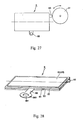
- Fig. 28 is perspective view illustrating a variant of the vibrating element shown in Fig. 27.
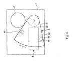
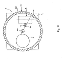
- Fig. 36 is a plan sectional view illustrating a second variant of the electric instrument in the sixth embodiment.
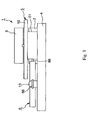
- the electric instrument 1 is an electro-optic instrument (optical apparatus) having an imaging portion 2, and an optical system 3.
- This electric instrument 1 is constituted from a base 4, a diaphragm portion 5, and a vibrating element 6.
- the imaging portion 2 is fixedly mounted on a surface 41 of the base 4 so that an imaging side of the imaging portion 2 faces upward.
- the optical system 3 is disposed above the imaging portion 2 so as to face toward the imaging portion 2 and to be spaced from the imaging portion 2 for a predetermined spacing, and is fixedly supported to a wall surface (not shown) extending from the base 4.
- the base 4 has a substantially plate-shaped structure, and is a base for mounting the imaging portion 2, the optical system 3, the diaphragm portion 5 and the vibrating element 6.
- the electrodes 61b, 61d lying at the other diagonal line in the front face on the piezoelectric element 62 are electrically connected to the electrode 65b, 65d lying at a corresponding diagonal line in the back face on the piezoelectric element 64, and these electrodes 61b, 61d, 65b, and 65d are connected to the outer conducting circuit.
- the electrodes 61a-61d and 65a-65d are conducted as these combinations by application of the voltage from the conducting circuit.
- to conduct the electrodes in either combination can be arbitrarily selected based on the constitution of the conducting circuit described later.
- an arm portion 68 is arranged at a position of a vibrational node of the vibrating element 6 on the side surface of the vibrating element 6.
- the point of the vibrational node may be appropriately determined within an obvious scope of one skilled in the art using known methods such as vibration analysis.
- the vibrational node may be located at substantial center of the longitudinal direction of the vibrating element 6. Therefore, the arm portion 68 is provided at the substantial center of the long side of the vibrating element 6 in the electric instrument 1.
- Figs. 8 and 9 are explanatory drawings each showing an action of the vibrating element shown in Figs. 1-7.
- Fig. 8 shows a case where the rotor 51 rotates in a counterclockwise direction in the drawing
- Fig. 9 shows a case where the rotor 51 rotates in a direction reverse to the direction shown in Fig. 8 (i.e., in a clockwise direction).
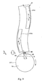
- the vibrating element 6 undergoes micro vibration bending as a substantial S shape.
- the contact portion 66 of the vibrating element 6 undergoes vibration (reciprocates) in a slanting direction represented by an arrow b, or the contact portion 66 is displaced along a substantially elliptic shape, i.e., vibrates (moves) in an elliptical manner as represented by an arrow c.
- the rotor 51 receives frictional force (or pushing force) from the contact portion 66 by this movement.
- great frictional force is provided between the contact portion 66 and the outer circumferential surface 511 by a component S1 corresponding to the radial direction of an vibrating displacement S of the contact portion 66 (displacement in a radial direction of the rotor 51), and further turning force generated in a counterclockwise direction in Fig. 8 is provided to the rotor 51 by a component S2 corresponding to circumferential direction of the vibrating displacement S (displacement in a circumferential direction of the rotor 51).
- the rotor 51 rotates in the counterclockwise direction by repeatedly receiving the pushing force from the contact portion 66 at a high speed.
- the electrodes 61b, 61d, 65b, and 65d are conducted. These electrodes are conducted symmetrical to the condition shown in Fig. 8. Then, the vibrating element 6 undergoes vibration symmetrical to the condition shown in Fig. 8, whereby the rotor 51 rotates in a clockwise direction in the drawing by receiving the pushing force from the contact portion 66. In this way, in the electric instrument 1, there is an advantage that the rotor 51 can rotate (be driven) in either the clockwise direction or the counterclockwise direction by selecting a conducting pattern.
- the electrodes 61a, 61c, 65a, and 65c to which a power is not applied (not activated) constitute vibration detecting means for detecting the vibration of the vibrating element 6.
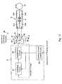
- Fig. 10 is a block diagram illustrating a conducting circuit of the vibrating element described in Figs. 1-9.
- the conducting circuit 20 is provided with a drive circuit 8 and a switch 9.
- the conducting circuit 20 applies an AC voltage to the vibrating element 6 to drive the vibrating element 6.
- the conducting circuit 20 has a function for switching vibrating modes of the vibrating element 6 by selecting the conducting pattern, and a function for feedback controlling the vibration of the vibrating element 6 by detecting the voltage value of the vibrating element 6.
- the drive circuit 8 includes an oscillating circuit 81, an amplification circuit 82, and a rotating amount control circuit 83.
- the oscillating circuit 81 generates an AC voltage to be outputted to the amplification circuit 82
- the amplification circuit 82 amplifies the AC voltage to apply the amplified AC voltage to the vibrating element 6.
- the rotating amount control circuit 83 controls both the oscillating circuit 81 and the amplification circuit 82, and adjusts the AC voltage applied to the vibrating element 6 so that the rotating amount of the rotor 51 becomes a target value instructed.
- the switch 9 switches between conducting electrodes to which the AC voltage is applied and electrodes to be used as vibration detecting means, thereby switching a rotative direction of the rotor 51.
- the switch 9 has two switching sections 91, 92 that operate simultaneously with each other.
- the electrode 61d of the vibrating element 6 is connected to a terminal 97 of the switching section 91.
- the electrode 61a is connected to a terminal 98 of the switching section 92.
- a terminal 93 of the switching section 91 and a terminal 96 of the switching section 92 each is connected to an output side of the amplification circuit 82 of the drive circuit 8, and an AC voltage from the amplification circuit 82 is applied to the vibrating element 6 via each of the terminals 93, 96.
- a terminal 94 of the switching section 91 and a terminal 95 of the switching section 92 each is connected to an input side of the oscillating circuit 81 of the drive circuit 8.
- the electrodes 61b, 61d, 65b, and 65d of the vibrating element 6 are conducted to the input side of the oscillating circuit 81 of the drive circuit 8. These electrodes constitute detecting electrodes during driven of the vibrating element 6, which are used for detecting a voltage to be induced between the reinforcing plate 63 and each of the electrodes 61b, 61d, 65b, and 65d (i.e., induced voltage). Based on the detected voltage, the oscillating circuit 81 outputs an AC voltage having a frequency (resonant frequency) at which amplitude of the vibrating element 6 becomes maximum, i.e., the detected voltage becomes maximum.
- the rotating amount control circuit 83 operates (controls) the oscillating circuit 81 and the amplification circuit 82 until a rotating amount of the rotor 51 becomes a target value instructed, thereby driving the vibrating element 6 to rotate the rotor 51.
- the electric instrument 1 since in-plan vibration of the vibrating element 6 can be converted to rotation of the rotor 51, it is possible to reduce energy loss caused by this conversion and to obtain high drive efficiency. Further, the contact portion 66 of the vibrating element 6 biases to the rotor 51 with a frictional contact condition while the rotor 51 is stopping, it is possible to prevent the rotation of the rotor 51 and to hold the rotor 51 at a stopping position stably. Moreover, since the rotor 51 can alternatively rotate in the forward and reverse directions using a signal vibrating element 6, a number of components of the electric instrument 1 can be reduced in comparison with a case where two dedicated vibrating elements are respectively provided for the moving (driving) directions.
- a length of the body portion of the vibrating element 6 in the longitudinal direction (the direction in which the vibrating element 6 undergoes expansion and contraction by the application of the AC voltage), i.e. , a length of the long side of the vibrating element 6 is determined to be a length L
- the lower limit of the length L may be about 1mm.
- the amplitude generated by the vibration of the contact portion 66 of the vibrating element 6 cannot overcome surface roughness of the rotor (driven element) 51.
- the vibrating element 6 can undergo extension and contraction at a drive time so that the vibrating element 6 can overcome the surface roughness of the rotor (driven element) 51 in a direction to give the driving force to the rotor 51.
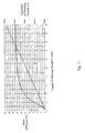
- Fig. 11 is a graph showing amplitude of the vibrating element and a drive efficiency of the vibrating element against the size of the vibrating element.
- the horizontal axis represents a length L (mm) of the vibrating element 6, and the perpendicular axis represents amplitude (m) of the vibrating element and drive efficiency (%) .
- a method of calculating the amplitude and the drive efficiency of the vibrating element 6 will be described later in detail.
- the length L of the vibrating element 6 is to be determined at a range in which the length L is more than 1mm. This makes it possible to drive the rotor (driven element) 51 suitably. Further, a change rate in the drive efficiency of the vibrating element 6 becomes smaller when the length L is more than 3mm. Therefore, it is preferable that the length L of the vibrating element 6 is more than 3mm in the electric instrument 1. Since a change in the drive efficiency due to uneven of the length L is prevented in this range, it is possible to drive the vibrating element 6 stably.
- amplitude u of the vibrating element 6 is calculated as follows.
- u Q ⁇ d ⁇ V ⁇ L (where Q is a mechanical quality coefficient.)
- Q is reciprocal of energy loss rate on the vibration per unit cycle of the vibrating element 6.
- the mechanical quality coefficient Q is constituted from a loss rate L 1 due to pressurization, contact, internal loss, or the like, and a loss rate L 2 due to the arm portion 68 of the vibrating element 6.
- the loss rate L 1 is thought of as a constant value.
- the formula for thee drive efficiency of the vibrating element 6 is set up. Then, the drive efficiency ⁇ , the mechanical quality coefficient Q, and the electromechanical coupling coefficient k v 2 are actually measured, the constant values C 1 -C 3 , and L 1 are calculated using the formulas (1)-(3) mentioned above. Thus, the drive efficiency ⁇ of the vibrating element 6 is calculated (computed).
- the upper limit of the length L of the body portion of the vibrating element 6 in the direction in which the contact portion 66 protrudes is to be determined to about 20mm. This reason is as follows.
- shock voltage a voltage due to this shock
- the piezoelectric elements 62, 64 The longer the length L of the piezoelectric element 62 or 64 is, the larger the shock voltage becomes.
- the shock voltage becomes more than a predetermined voltage value
- a drive IC of the electric instrument 1 is electrically destroyed.
- the endurance voltage for the drive IC is generally about the power supply voltage pulse 0.6V.
- the drive IC is electrically destroyed when the shock voltage becomes over 3. 6V.
- the electric instrument 1 of the present invention has a characteristic on the point where the maximum value of the shock voltage is restricted (controlled) by adjusting the length L of the vibrating element 6. This makes it possible to prevent the drive IC from being electrically destroyed due to the shock such as fall or the like.
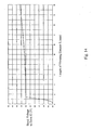
- Fig. 14 is a graph showing a relationship between a size of the vibrating element and the shock voltage to the drive IC.
- the horizontal axis represents the length L (mm) of the vibrating element 6, and the perpendicular axis represents shock voltage (V) applied to the drive IC.
- the shock voltage is measured against each of the lengths L of the vibrating element 6 by carrying out fall down test for the vibrating element 6.
- a method of calculating the shock voltage will be described later in detail.
- the power supply voltage of the drive IC in this electric instrument 1 is 3.0V, it is preferable that the endurance voltage for the drive IC is 3. 6V, and more preferable that it is 3.5V.
- the length L of the vibrating element 6 is set so that the shock voltage applied to the drive IC becomes less than the endurance voltage for the drive IC.
- the shock voltage applied to the drive IC in this shock voltage becomes less than the endurance voltage for the drive IC.
- the shock voltage applied to the drive IC exceeds 3.6V, i.e., the endurance voltage for the drive IC in the case where the length L is over 20mm. Therefore, in the electric instrument 1, the upper limit of the length L of the vibrating element 6 is to be determined to about 20mm.
- the endurance voltage is set to 3. 5V more strictly, it is preferable that the upper limit of the length L of the vibrating element 6 is about 18mm.
- the electric instrument 1 can have a margin (or clearance) between the shock voltage and the endurance voltage for the drive IC, it is possible to prevent the electrical breakage of the drive IC more surely.
- the length L of the vibrating element 6 is less than 13mm, and it is further more preferable that the length L is less than 7mm.
- the electric instrument 1 can have larger margin (or clearance) , it is possible to prevent the electrical breakage of the drive IC still more surely even though variation in the value of resistance of a protection diode is wide.
- Fig. 15 is an explanatory drawing showing a method of calculating the shock voltage applied to the drive IC.
- the circuit shown in Fig. 15 is an equivalent circuit of a protection circuit of the drive IC that a general electric instrument has.
- symbol Vcc represents a power supply voltage
- symbols D 1 , D 2 each represents a protection diode for protecting the drive IC
- symbol C represents a capacitor having an equivalent capacity of the drive IC.
- values of forward resistance of the protection diodes D 1 , D 2 is 0.1 ⁇
- capacitance of the capacitor C is less than 100pF.
- the calculation of the shock voltage is carried out by the fall down test.
- a quantity of electric charge q v flowing through either the protection diode D1 or D2 is represented as follows.
- the current flows through the protection diode D1 when a high voltage is generated in the drive IC, while the current flows through the protection diode D2 when a low voltage is generated in the drive IC. Since only the breakage of the drive IC is a problem, it is thought about only a case where a high voltage is applied to the drive IC.
- the proportionality constant C4 and the collision time ⁇ t are obtained from the waveform of the voltage generated while the vibrating element 6 falls.
- the length L of the body portion of the vibrating element 6 is to be determined in consideration of the maximum stress generated in the piezoelectric elements 62, 64.
- Fig. 16 is a graph showing a relationship between the size and a maximum stress generated in a piezoelectric element.
- the horizontal axis represents the length L (mm) of the vibrating element 6, and the perpendicular axis represents the maximum stress (N/m 2 ) generated in the piezoelectric elements 62, 64.
- the maximum stress is a maximum value of the stress generated in the piezoelectric elements 62, 64 when the vibrating element 6 receives the shock from the outside due to fall or the like.
- the maximum stress is measured against each of the length L of the vibrating element 6 by means of the fall down test for the vibrating element 6.
- Fig. 16 is the graph in which the width W of the arm portion 68 for supporting the vibrating element6 (see Fig. 12) is 0.5mm. a method of calculating the maximum stress will be described later in detail.
- the electric instrument 1 of the present invention has a characteristic on the point where physical breakage of the piezoelectric elements 62, 64 due to the shock is restricted (controlled) by adjusting the length L of the vibrating element 6.
- the maximum stress that the piezoelectric elements 62, 64 receive at the shock time is calculated, and then the length L of the vibrating element 6 is adjusted so that the maximum value is less than a permissible stress of the piezoelectric elements 62,64.
- the endurance stress of the piezoelectric elements 62, 64 made from plumbum zirconate titanate (PZT) is 1 ⁇ 10 8 (N / m 2 ) .
- PZT plumbum zirconate titanate
- the length L of the vibrating element 6 in the longitudinal direction is less than 18mm in the electric instrument 1. This makes it possible to restrict the maximum stress generated in the piezoelectric elements 62, 64 at the shock time to less than the permissible stress. Therefore, it is possible to effectively prevent the physical breakage of the piezoelectric elements 62, 64 due to the shock.
- the drive characteristics of the vibrating element 6 diminish (come down) due to outbreak of minor defect in the piezoelectric elements 62, 64.
- the drive characteristics of the vibrating element 6 diminish at the range between 6 ⁇ 10 7 to 1 ⁇ 10 8 (N / m 2 ).
- the length L of the vibrating element is less than 7mm based on the graph shown in Fig. 16. This makes it possible to prevent the breakage of the piezoelectric elements 62, 64 more surely while maintaining the drive characteristics of the vibrating element 6.
- the length L of the vibrating element 6 is less than 6mm.
- the electric instrument 1 can have a margin (or clearance) between the maximum stress generated at the shock time and the permissible stress of the piezoelectric elements 62, 64, it is possible to prevent the physical breakage of the piezoelectric elements 62, 64 more surely.
- the permissible stress of the piezoelectric elements 62, 64 varies according to quality of material thereof. Therefore, it is preferable that the length L of the vibrating element 6 is appropriately design-changed within an obvious scope of one skilled in the art in consideration with the quality of material of the piezoelectric elements 62, 64.
- Fig. 17 is a graph showing a relationship between the width of the arm portion and the mechanical quality coefficient.
- the width w of the arm portion 68 is less than 0.5mm so that the mechanical quality coefficient Q becomes more than 700.
- the width w of the arm portion 68 for supporting the vibrating element 6 is set to 0.5mm, namely, the upper limit of the width w.
- Fig. 18 is an explanatory drawing showing a method of measuring the maximum stress generated in the piezoelectric element.
- Fig. 18 shows a method of measuring the maximum stress generated in the piezoelectric element 62, 64 when shock is applied to the vibrating element 6 from the outside thereof.
- a portable electric instrument such as a watch or the like
- impact acceleration applied to the vibrating element 6 becomes 10,000 (G) at this time.
- the maximum stress generated in the piezoelectric elements 62, 64 when shock is applied to the vibrating element 6 by falling it is measured.
- the piezoelectric element made from plumbum zirconate titanate (PZT) is utilized.
- the reinforcing plate 63 of the vibrating element 6 has arm portions 68, 68 at central portions of both side surfaces in the longitudinal direction of the vibrating element 6, respectively, and the vibrating element 6 is fixedly provided between walls by means of the arm portions 68, 68.
- Impact acceleration is applied to the vibrating element 6 by falling it from the height of about 1m. This makes the shadow area in Fig. 18 be broken. This is because energy of movement generated by the fall of the vibrating element 6 is consumed as (converted into) distortion of the shadow area.
- the energy of movement T that the vibrating element 6 obtains by the impact acceleration is represented as follows.
- T ⁇ ⁇ L ⁇ A ⁇ t ⁇ ( ⁇ ⁇ t 0 ) 2 / 2
- a length of the body portion of the vibrating element 6 in a direction substantially perpendicular to the longitudinal direction i.e., a length of the body portion in the direction substantially perpendicular to the direction in which the contact portion 66 protrudes
- the width A is not especially limited. However, it is preferable that the width A is about 0.1 to 6.0mm. Further, it is more preferable that the width A is about 0.2 to 2.0mm.
- the width A is less than 0.1mm, adhesive force between the reinforcing plate 63 and each of the piezoelectric elements 62, 64 is deficient. Thus, there is a case where they are separated from each other (peel off) when the vibrating element 6 falls. Further, in the case where the width A is less than 0.2mm, deterioration of the drive characteristics may occur.
- a planar structure of the body portion of the vibrating element 6 is a substantially rectangular shape. This is preferable because the number of products becomes large and a yield rate is improved when the piezoelectric elements 62, 64 of the vibrating element 6 are manufactured by dice cutting (dicing) or the like.
- the vibrating element 6 (the body portion of the vibrating element 6) has a thinner plate-shaped structure. This is preferable on the point that it is possible to make the electric instrument 1 thinner.
- the present invention is not limited to these.
- the shape and thickness of the vibrating element 6 is not especially limited.
- an electro-optic instrument is mentioned as an example of the electric instrument 1.
- the present invention is not limited to this instrument.
- the ultrasonic motor and the operating apparatus mentioned above may be applied to other electric instruments.
- the rotor 51 (the diaphragm portion 5) is used as a driven element, and the switching mechanism for the diaphragm portion of the optical system is constituted by driving the vibrating element 6.
- a switching mechanism for the optical system such as a switching mechanism for the filter, mechanical shutter mechanism, or the like may be constructed using other driven element.
- the switching mechanism mentioned above can have at least one of the diaphragm portion, the filter portion, and the mechanical shutter, for example.
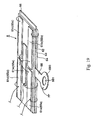
- Fig. 19 is a perspective view of a vibrating element in a second embodiment of an electric instrument according to the present invention.
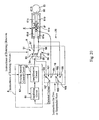
- Fig. 20 is a block diagram illustrating circuitry of a conducting circuit in the second embodiment according to the present invention.
- the electric instrument 1 in the second embodiment has a first mode in which a rotor 51, i.e. , a diaphragm portion 5 is maintained in a stopping state; a second mode in which the rotor 51 can be rotated (the rotor 51 lies in a free state), i.e., the diaphragm portion 5 can be displaced (the diaphragm portion 5 lies in a free state); a third mode in which the rotor 51 is rotated in a forward direction; and a fourth mode in which the rotor 51 is rotated in a reverse direction.
- the electric instrument 1 is adapted to select one of the first, second, third, and fourth modes by selecting any of conducting patterns to each of electrodes to change a vibrating pattern of a vibrating element 6.
- the piezoelectric element 62 is substantially equally divided (partitioned) into four rectangular areas.
- the rectangular electrodes 61a, 61b, 61c, and 61d are respectively disposed at the divided areas.
- the piezoelectric element 64 is divided (partitioned) into four rectangular areas.
- the rectangular electrodes 65a, 65b, 65c, and 65d are respectively disposed at the divided areas.
- each of the electrodes 61e, 65e substantially corresponds with that (the long side direction) of the vibrating element 6.
- the electrodes 61e and 65e are detecting electrodes that are used for detecting a voltage to be induced between a reinforcing plate 63 and each of electrodes 61e, 65e, i.e., a voltage to be induced (an induced voltage) in response to a component in a longitudinal direction of the vibration of the vibrating element 6 (i.e., a component of the longitudinal vibration). Further, the electrodes 61e, 65e are respectively used at the second mode.
- the electrodes 65a, 65b, 65c, 65d, and 65e are disposed at the back faces of the electrodes 61a, 61b, 61c, 61d, and 61e, respectively.
- the electrodes 61a, 61c lying at one diagonal line in a front face are electrically connected to the electrodes 65a, 65c lying at a corresponding diagonal line in the back face.
- the electrodes 61b, 61d lying at the other diagonal line in the front face are electrically connected to the electrode 65b, 65d lying at corresponding diagonal line in the back face.
- the conducting circuit 20 of the electric instrument 1 in the second embodiment has: a switch 9 ; a switch 16; and a drive circuit 8 provided with an oscillating circuit 81, an amplification circuit 82, and a rotating amount control circuit 83.
- the switch 9 is switching means for switching between conducting electrodes and electrodes to be used as vibration detecting means. When the switch 9 is switched, a rotative direction of the rotor 51 can be changed.
- the switch 9 has two switching sections 91, 92 that operate simultaneously with each other.
- the electrode 61d of the vibrating element 6 is connected to a terminal 97 of the switching section 91.
- the electrode 61a is connected to a terminal 98 of the switching section 92.
- each of a terminal 93 of the switching section 91 and a terminal 96 of the switching section 92 is connected to an output side of the amplification circuit 82 in the drive circuit 8.
- An AC voltage is applied from the amplification circuit 82 to each of the terminals 93, 96.
- the reinforcing plate 63 of the vibrating element 6 is connected to ground.
- each of a terminal 94 of the switching section 91 and a terminal 95 of the switching section 92 is connected to an input side of the oscillating circuit 81 in the drive circuit 8.
- the switch 16 has two switching sections 161, 162 that operate simultaneously with each other.
- a terminal 163 of the switching portion 161 is connected to the terminals 94, 95 of the switch 9.
- a terminal 164 is connected to the electrode 61e of the vibrating element 6.
- a terminal 167 of the switching portion 162 is connected to the input side of the oscillating circuit 81 in the drive circuit 8.
- a terminal 166 of the switching portion 162 is connected to the terminal 98 of the switch 9 and the electrode 61a of the vibrating element 6.
- a terminal 168 is connected to the terminal 97 of the switch 9 and the electrode 61d of the vibrating element 6.
- the contact portion 66 of the vibrating element 6 abuts on (is pressed to) the rotor 51, and the rotor 51 is maintained in a stopping state by frictional force between the contact portion 66 and the rotor 51.
- vibration is excited in a direction substantially perpendicular to a tangent line at a portion where the outer circumferential surface 511 of the rotor 51 abuts on the contact portion 66.
- an electric power is supplied to the electrodes 61a, 61b, 61c, 61d, 65a, 65b, 65c, and 65d at both diagonal lines of both surfaces of the vibrating element 6, whereby an AC voltage is applied between the reinforcing plate 63 and each of the electrodes 61a, 61b, 61c, 61d, 65a, 65b, 65c, and 65d.
- the vibrating element 6 repeatedly undergo extension and contraction in its longitudinal direction (in its long side direction), i.e., vibrate (longitudinally vibrate) with minute amplitude in its longitudinal direction.
- the contact portion 66 of the vibrating element 6 undergoes vibration (reciprocates) in its longitudinal direction (in its long side direction).
- the rotor 51 When the vibrating element 6 undergoes contraction, the rotor 51 is away from the contact portion 66 so that frictional force between the rotor 51 and the contact portion 66 disappears or decreased and therefore the rotor 51 is in a free state. Thus, the rotor 51 can be freely rotated in both counterclockwise and clockwise directions in Fig. 20. This makes it possible to freely move the diaphragm portion 5.
- the rotor 51 receives pushing force from the contact portion 66. However, since the direction of the pushing force is substantially perpendicular to the tangent line, the rotor 51 rotates in neither the counterclockwise direction nor the clockwise direction in Fig. 20, and therefore the diaphragm portion 5 does not move.
- the rotor 51 i.e. , the diaphragm portion 5 lies in a free state by vibration of the vibrating element 6, and can freely move in both directions.
- vibration is excited, which at least has a displacing component of vibration in the forward rotating direction of the rotor 51 (the circumferential direction component S2 shown in Fig. 8).
- an electric power is supplied to the electrodes 61a, 61c, 65a, and 65c that are located at one diagonal line of the vibrating element 6, whereby an AC voltage is applied between the reinforcing plate 63 and each of the electrodes 61a, 61c, 65a, and 65c.
- this makes the rotor 51 rotate in a counterclockwise direction in Fig. 20 (in the forward direction) .
- the electrodes 61b, 61d, 65b, and 65d located at the other diagonal line of the vibrating element 6 to which the electric power is not applied are used as vibration detecting means for detecting vibration of the vibrating element 6.
- vibration is excited, which at least has a displacing component of vibration in the reverse rotating direction of the rotor 51 (the circumferential direction component S2 shown in Fig. 9).
- an electric power is supplied to the electrodes 61b, 61d, 65b, and 65d that are located at one diagonal line of the vibrating element 6, whereby an AC voltage is applied between the reinforcing plate 63 and each of the electrodes 61b, 61d, 65b, and 65d.
- this makes the rotor 51 rotate in a clockwise direction in Fig. 20 (in the reverse direction) .
- the electrodes 61a, 61c, 65a, and 65c located at the diagonal line of the vibrating element 6 to which the electric power is not applied are used as vibration detecting means for detecting vibration of the vibrating element 6.
- the output side of the amplification circuit 82 in the drive circuit 8 is conducted to the electrodes 61a, 61c, 65a, and 65c of the vibrating element 6, and the input side of the oscillating circuit 81 in the drive circuit 8 is conducted to the electrodes 61b, 61d, 65b, and 65d of the vibrating element 6.
- Each of the oscillating circuit 81 and the amplification circuit 82 of the drive circuit 8 is controlled by the rotating amount control circuit 83.
- An AC voltage outputted from the oscillating circuit 81 is amplified by the amplification circuit 82 and then applied between the reinforcing plate 63 and each of the electrodes 61a, 61c, 65a, and 65c.
- each of the portions corresponding to the electrodes 61a, 61c, 65a, and 65c of the vibrating element 6 undergoes expansion and contraction repeatedly, and the contact portion 66 of the vibrating element 6 undergoes vibration (reciprocates) in a slanting direction as represented by the arrow b shown in Fig. 8, and vibrates (moves) in an elliptical manner as represented by the arrow c shown in Fig. 8.
- the rotor 51 receives the frictional force (pushing force) from the contact portion 66 when the portions corresponding to the electrodes 61a, 61c, 65a, and 65c of the vibrating element 6 are extended, and this repeating frictional force (pushing force) moves (rotates) the rotor 51 in the counterclockwise direction in Fig. 1 (in the forward direction).
- the electrodes 61b, 61d, 65b, and 65d to which an AC voltage is not applied (not activated) function as detecting electrodes that are used to detect a voltage to be induced between the reinforcing plate 63 and each of the electrodes 61b, 61d, 65b, and 65d (induced voltage).
- the detected induced voltage (detected voltage) is inputted to the oscillating circuit 81, and then based on such detected voltage, the oscillating circuit 81 outputs an AC voltage having a frequency (resonant frequency) at which amplitude of the vibrating element 6 becomes maximum, namely, the detected voltage becomes maximum. This makes it possible to move the diaphragm portion 5 efficiently.
- the rotating amount control circuit 83 controls operation for conducting to each of those electrodes based on the instructed rotating amount (target value) of the rotor 51.
- the rotating amount control circuit 83 allows the oscillating circuit 81 and the amplification circuit 82 to activate until the rotating amount of the rotor 51 reaches the instructed rotating amount (target value) of the rotor 51, thereby driving the vibrating element 6 and rotating the rotor 51.
- the output side of the amplification circuit 82 in the drive circuit 8 is conducted to the electrodes 61b, 61d, 65b, and 65d of the vibrating element 6, and the input side of the oscillating circuit 81 in the drive circuit 8 is conducted to the electrodes 61a, 61c, 65a, and 65c of the vibrating element 6. Since the following operations are the same as those of the case where the instructions indicate that the rotor 51 is to be rotated in the counterclockwise direction in Fig. 20, a description thereof will be omitted.
- the switch 16 is switched so that the terminal 163 and the terminal 167 of the switch 16 are connected, and the terminal 165 and the terminal 168 of the switch 16 are connected.
- the rotating amount control circuit 83 does not allow the oscillating circuit 81 and the amplification circuit 82 to activate. Namely, an AC voltage is not applied to any of the electrodes of the vibrating element 6.
- the contact portion 66 of the vibrating element 6 is in pushing contact with (abuts on) the rotor 51, and the frictional force between the contact portion 66 and the rotor 51 keeps the rotor 51 in the stopping state.
- the switches 9 and 16 may be switched in any manner as long as an AC voltage is not applied to any of the electrodes of the vibrating element 6.
- the switch 16 is switched so that the terminal 164 and the terminal 167 of the switch 16 are connected, and the terminal 166 and the terminal 168 of the switch 16 are connected.
- the output side of the amplification circuit 82 of the drive circuit 8 is conducted to the electrodes 61a, 61b, 61c, 61d, 65a, 65b, 65c, and 65d of the vibrating element 6, and the electrodes 61e and 65e of the vibrating element 6 are conducted to the input side of the oscillating circuit 81 of the drive circuit 8.
- An AC voltage outputted from the oscillating circuit 81 is amplified by the amplification circuit 82 and then applied between the reinforcing plate 63 and each of the electrodes 61a, 61b, 61c, 61d, 65a, 65b, 65c, and 65d.
- the contact portion 66 of the vibrating element 6 undergoes vibration (reciprocates) in its longitudinal direction, whereby the rotor 51, i.e., the diaphragm portion 5 becomes a free state, and it is possible to freely rotate the rotor 5 (diaphragm portion 5) in both of the directions in Fig. 20.
- the voltage (induced voltage) induced between the reinforcing plate 63 and each of the electrodes 61e and 65e is detected from each of the electrodes 61e and 65e.
- the detected induced voltage (detected voltage) is inputted to the oscillating circuit 81, and thereafter, based on the detected voltage, the oscillating circuit 81 outputs an AC voltage having a frequency at which amplitude of the longitudinal vibration of the vibrating element 6 becomes maximum, namely, the detected voltage becomes maximum. This makes it possible to rotate the rotor 51, i.e., the diaphragm portion 5 more smoothly.
- the switch 9 may be switched in any manner.
- any state from the four states which includes a state where the rotor 51 (diaphragm portion 5) is kept in a stopping state, i.e. , a state of high friction, a state where the rotor 51 (diaphragm portion 5) is allowed to be rotated (or be moved) (i.e., the rotor 51 and the diaphragm portion 5 are set in a free state), i.e. , a state of low friction, a state where the rotor 51 is rotated in the forward direction, and a state where the rotor 51 is rotated in the reverse direction, there is wide applicability.
- the case where the electrodes to drive the vibrating element 6 are divided into four sections has been described.
- this is just one example for selectively exciting the longitudinal vibration and the bending vibration of the vibrating element 6, and in the present invention, the structure and the method of driving the vibrating element 6 are not limited to the above-mentioned ones.
- the electric instrument 1 is adapted so that the third mode or the fourth mode may be omitted, and the rotor 51 may be rotated in only one direction. Even in this case, the diaphragm portion 5 can reciprocate (i.e., move) in both of the directions in Fig. 20 using the only one vibrating element 6.
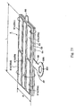
- Fig. 21 is a perspective view illustrating a vibrating element in a third embodiment of an electric instrument according to the present invention.
- an upper side is referred to as "upper”
- a lower side is referred to as “lower”
- a right side is referred to as “right”
- a left side is referred to as "left.”
- the electric instrument 1 in the third embodiment has characteristics on the point that the electric instrument 1 can further employ a fifth mode and a sixth mode in which longitudinal vibration and bending vibration are combined, in addition to the first to fourth modes described in the second embodiment.
- the fifth mode and the sixth mode can be arbitrarily selected by changing a conducting pattern to each of electrodes 61a-61d, 61f, 65a-65d, and 65f in the same way as the first to fourth modes.
- the vibrating element 6 of the electric instrument 1 has an electrode 61f at the upper side of a piezoelectric element 62 in Fig. 21 and an electrode 65f at the lower side thereof in place of the detecting electrodes 61e and 65e in the second embodiment.
- the electrodes 61f and 65f are rectangular and plate-shaped, and has a substantially same length as a length in a longitudinal direction of the vibrating element 6.
- the electrodes 61f and 65f are located at a center of the vibrating element 6 along its longitudinal direction. Further, the electrode 61f is electrically connected to the electrode 65f between the front face and the back face of the vibrating element 6.
- the electrodes 61f and 65f are also electrically connected to the conducting circuit 20 in the same way as the other electrodes 61a-61d and 65a-65d (the electrodes 65a-65d are not shown in Fig. 21.).
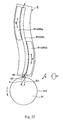
- Fig. 22 is a plan view showing a vibrating state of the vibrating element shown in Fig. 21.
- an electric power is applied to the electrodes 61a, 61c, 65a, and 65c that are located at one diagonal line of the vibrating element 6, whereby an AC voltage is applied between the reinforcing plate 63 and each of the electrodes 61a, 61c, 65a, and 65c.
- each of portions of the vibrating element 6 corresponding to these electrodes repeatedly undergoes extension and contraction so that the entire vibrating element 6 undergoes bending secondary vibration.
- the contact portion 66 of the vibrating element 6 undergoes vibration (reciprocates) in a slanting direction represented by an arrow b in Fig.
- the rotor 51 repeatedly receives frictional force (pushing force) from the contact portion 66 so as to rotate in the counterclockwise direction in Fig. 22 (in the forward direction).
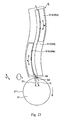
- an electric power is further applied to the electrodes 61f and 65f at the center of the vibrating element 6, whereby portions of the piezoelectric elements 62, 64 corresponding to the electrodes 61f and 65f repeatedly and partly undergoes extension and contraction at a high speed. Then, portions on the centerline in the longitudinal direction of the vibrating element 6 undergo longitudinal vibration at minute amplitude along its longitudinal direction. This is referred to as longitudinal primary vibration.
- longitudinal primary vibration By the longitudinal primary vibration, the contact portion 66 increases the pushing force in the longitudinal direction of the vibrating element 6 to bias the rotor 51 with the increased (stronger) pushing force. This makes it possible to obtain high driving force in comparison with the case where the vibrating element 6 is driven by only the bending secondary vibration.
- the oscillating circuit 81 outputs an AC voltage having frequency (resonant frequency) at which amplitude of the vibrating element 6 becomes maximum, i.e., the induced voltage becomes maximum based on the detected induced voltage.
- the electrodes 61b, 61d, 65b, and 65d to which the electric power is not applied operate in the same way as those in the first embodiment.
- Fig. 24 is a perspective view illustrating a variant of the vibrating element shown in Fig. 21.
- the vibrating element 6 has a single electrode 61g integrating the electrodes 61a, 61c, and 61f at the same position as those of the electrodes in place of these electrodes 61a, 61c, and 61f in comparison with the vibrating element 6 described in Fig. 21.
- the vibrating element 6 has a single electrode 65g integrating the electrodes 65a, 65c, and 65f at the same position as those of the electrodes in place of these electrodes 65a, 65c, and 65f.
- the electrode 65g is not shown in Fig. 24, but reference numerals of the electrode is merely designated using parentheses.
- the electrode 61d is provided independent of the electrode 65d.
- the electrodes 61b, 65b, and 65d are omitted in this vibrating element 6.
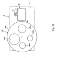
- the shielding plate 550 is rotated to switch any one of the openings 553a-553d.
- the rotating plate 55 serves as a variable diaphragm portion for switching light intensity from the optical system 3 toward the imaging portion 2 in a stepwise manner.
- the rotating plate 55 may have color filters 554a-554d each having a mutually different color in place of the openings 553a-553d (see Fig. 35) .
- the rotating plate 55 serves as a variable filter portion for switching light intensity from the optical system 3 toward the imaging portion 2 in a stepwise manner by the same operation as that mentioned above.
- the end portion 552 is provided on the rotating plate 55, and the contact portion 66 of the vibrating element 6 abuts on the inner wall surface of the end portion 552 to drive (rotate) the rotating plate 55 from the inner side thereof.
- the present invention is not limited to this structure.
- the electric instrument 1 may be adapted so that the vibrating element 6 is provided at the outer circumferential side of the rotating plate 55, and the rotating plate 55 is driven from the outer circumferential side. This makes it possible to utilize variations of arrangement of the vibrating element 6 against the rotating plate 55.
- the present invention may combine any two or more constitutions (characteristics) in all the embodiments and all the variants described above.
Landscapes
- Physics & Mathematics (AREA)
- General Physics & Mathematics (AREA)
- Optics & Photonics (AREA)
- General Electrical Machinery Utilizing Piezoelectricity, Electrostriction Or Magnetostriction (AREA)
Abstract
Description
wherein driving force is generated by the vibration of the vibrating element, and the driven element is driven by means of the driving force from the ultrasonic motor.
a switching mechanism for the optical system, the switching mechanism being operated in association with the driven element;
wherein driving force is generated by the vibration of the vibrating element, and the driven element is driven by means of the driving force from the ultrasonic motor.
wherein driving force is generated by the vibration of the vibrating element, and the driven element is driven by means of the driving force from the ultrasonic motor.
The piezoelectric constant d is an inherent value depending on the quality of the material of the piezoelectric element 62, or 64.
The mechanical quality coefficient Q is reciprocal of energy loss rate on the vibration per unit cycle of the vibrating element 6.
Uo ∝ a potential energy of the vibrating element 6 before fall
Ue = C4 × mgh (where m is mass of the vibrating element 6, h is a falling distance, and C4 is a proportionality constant.)

Claims (16)
- An ultrasonic motor comprising:wherein the vibrating element has a body portion and a length of the body portion in a direction in which the vibrating element extends and contracts by application of the AC voltage is 1 to 20mm.a vibrating element which includes a first piezoelectric element that undergoes extension and contraction by application of an AC voltage, a reinforcing plate having a contact portion and an arm portion, and a second piezoelectric element that undergoes extension and contraction by application of an AC voltage, the first piezoelectric element, the reinforcing plate and the second piezoelectric element being laminated in this order, and the vibrating element being fixedly mounted through the arm portion so that the contact portion abuts on a driven element;
- The ultrasonic motor as claimed in claim 1, wherein the length of the body portion in the extension-and-contraction direction is less than 18mm.
- The ultrasonic motor as claimed in claim 1, wherein the arm portion is arranged at a substantially central portion of the body portion in the extension-and-contraction direction.
- The ultrasonic motor as claimed in claim 1, wherein the body portion has a short side substantially perpendicular to the extension-and-contraction direction of the body portion, and the contact portion is arranged at a substantially central portion of the short side.
- The ultrasonic motor as claimed in claim 1, wherein the body portion has a short side substantially perpendicular to the extension-and-contraction direction of the body portion, and the contact portion is arranged at a portion of the short side other than a substantially central portion thereof.
- The ultrasonic motor as claimed in claim 1, wherein the body portion has a centerline in a direction parallel to the extension-and-contraction direction, and the contact portion is arranged at a portion other than the centerline.
- The ultrasonic motor as claimed in claim 1, wherein the contact portion is arranged so as to protrude in the extension-and-contraction direction partly.
- The ultrasonic motor as claimed in claim 1, wherein the vibrating element has a vibrational node, and the arm portion supports the vibrating element at the vibrational node.
- The ultrasonic motor as claimed in claim 1, wherein the length of body portion of the vibrating element in the extension-and-contraction direction is longer than that in a direction perpendicular to the extension-and-contraction direction.
- The ultrasonic motor as claimed in claim 1, wherein the vibrating element undergoes a complex vibration of combination of longitudinal vibration and bending vibration, and a resonant frequency of the longitudinal vibration is different from but close to that of the bending vibration.
- An operating apparatus comprising:wherein the vibrating element has a body portion and a length of the body portion in a direction in which the vibrating element extends and contracts by the application of the AC voltage is 1 to 20mm;a driven element; andan ultrasonic motor comprising:a vibrating element which includes a first piezoelectric element that undergoes extension and contraction by application of an AC voltage, a reinforcing plate having a contact portion and an arm portion, and a second piezoelectric element that undergoes extension and contraction by application of an AC voltage, the first piezoelectric element, the reinforcing plate and the second piezoelectric element being laminated in this order, and the vibrating element being supported through the arm portion so that the contact portion abuts on the driven element;
wherein driving force is generated by the vibration of the vibrating element, and the driven element is driven by means of the driving force from the ultrasonic motor. - The operating apparatus as claimed in claim 11, wherein the driven element has a rotor and the rotor is rotatively driven by means of the driving force from the ultrasonic motor.
- The operating apparatus as claimed in claim 11, wherein the driven element has a circumferential surface, and the contact portion of the ultrasonic motor abuts on the circumferential surface of the driven element so that the driven element is driven by means of the driving force from the ultrasonic motor.
- An optical apparatus comprising:wherein the vibrating element has a body portion and a length of the body portion in a direction in which the vibrating element extends and contracts by the application of the AC voltage is 1 to 20mm; andan optical system;a driven element;an ultrasonic motor comprising:a vibrating element which includes a first piezoelectric element that undergoes extension and contraction by application of an AC voltage, a reinforcing plate having a contact portion and an arm portion, and a second piezoelectric element that undergoes extension and contraction by application of an AC voltage, the first piezoelectric element, the reinforcing plate and the second piezoelectric element being laminated in this order, and the vibrating element being supported through the arm portion so that the contact portion abuts on the driven element;
a switching mechanism for the optical system, the switching mechanism being operated in association with the driven element;
wherein driving force is generated by the vibration of the vibrating element, and the driven element is driven by means of the driving force from the ultrasonic motor. - The optical apparatus as claimed in claim 14, wherein the switching mechanism has at least one of a diaphragm portion, a filter portion, and a mechanical shutter.
- An electric instrument comprising:wherein the vibrating element has a body portion and a length of the body portion in a direction in which the vibrating element extends and contracts by the application of the AC voltage is 1 to 20mm;a driven element; andan ultrasonic motor comprising:a vibrating element which includes a first piezoelectric element that undergoes extension and contraction by application of an AC voltage, a reinforcing plate having a contact portion and an arm portion, and a second piezoelectric element that undergoes extension and contraction by application of an AC voltage, the first piezoelectric element, the reinforcing plate and the second piezoelectric element being laminated in this order, and the vibrating element being supported through the arm portion so that the contact portion abuts on the driven element;
wherein driving force is generated by the vibration of the vibrating element, and the driven element is driven by means of the driving force from the ultrasonic motor.
Applications Claiming Priority (2)
| Application Number | Priority Date | Filing Date | Title |
|---|---|---|---|
| JP2003055019A JP2004266943A (en) | 2003-02-28 | 2003-02-28 | Ultrasonic motor, operating device, optical system switching mechanism and electric equipment |
| JP2003055019 | 2003-02-28 |
Publications (2)
| Publication Number | Publication Date |
|---|---|
| EP1453116A2 true EP1453116A2 (en) | 2004-09-01 |
| EP1453116A3 EP1453116A3 (en) | 2005-08-24 |
Family
ID=32767871
Family Applications (1)
| Application Number | Title | Priority Date | Filing Date |
|---|---|---|---|
| EP04004347A Withdrawn EP1453116A3 (en) | 2003-02-28 | 2004-02-26 | Ultrasonic motor and apparatus using the same |
Country Status (4)
| Country | Link |
|---|---|
| US (1) | US7116038B2 (en) |
| EP (1) | EP1453116A3 (en) |
| JP (1) | JP2004266943A (en) |
| CN (1) | CN100578907C (en) |
Cited By (4)
| Publication number | Priority date | Publication date | Assignee | Title |
|---|---|---|---|---|
| GB2446606A (en) * | 2006-12-02 | 2008-08-20 | Nanomotion Ltd | Camera aperture diaphragm with different sized apertures |
| CN106059384A (en) * | 2015-04-10 | 2016-10-26 | 佳能株式会社 | Vibration wave motor |
| EP3910401A1 (en) * | 2020-05-14 | 2021-11-17 | Vilniaus Gedimino technikos universitetas | Optical beam intensity control system with piezoelectric actuator |
| EP4325267A4 (en) * | 2021-04-14 | 2024-06-12 | Beijing Xiaomi Mobile Software Co., Ltd. | Optical filter switching device |
Families Citing this family (15)
| Publication number | Priority date | Publication date | Assignee | Title |
|---|---|---|---|---|
| EP2568595A3 (en) * | 1998-12-21 | 2013-05-15 | Seiko Epson Corporation | Piezoelectric actuator, timepiece, and portable device |
| KR100679914B1 (en) | 2005-05-27 | 2007-02-07 | 전자부품연구원 | Precision Rotary Drive Using Piezoelectric Transducer |
| JP4857886B2 (en) * | 2005-06-24 | 2012-01-18 | セイコーエプソン株式会社 | Shock-resistant device for piezoelectric actuator and electronic device equipped with the same |
| KR100817470B1 (en) * | 2006-10-24 | 2008-03-31 | 한국과학기술연구원 | Piezoelectric linear motor |
| JP2008306826A (en) | 2007-06-07 | 2008-12-18 | Seiko Epson Corp | Piezoelectric actuator and driving method thereof |
| DE102008053646A1 (en) * | 2008-10-29 | 2010-05-06 | Minebea Co., Ltd. | Linear drive with shock compensation |
| CN101996915B (en) * | 2009-08-13 | 2012-11-07 | 威控自动化机械股份有限公司 | Driving device and die bonder |
| JP4907738B1 (en) * | 2011-06-14 | 2012-04-04 | 株式会社根本杏林堂 | Injection device and method for controlling ultrasonic motor |
| DE102014209419B3 (en) * | 2014-05-19 | 2015-05-07 | Physik Instrumente (Pi) Gmbh & Co. Kg | ultrasonic actuator |
| CN104883090B (en) * | 2015-06-02 | 2017-03-22 | 北京大学 | Piezoelectric linear motor fused with shear piezoelectric actuator composite drive mode |
| JP6592993B2 (en) * | 2015-07-07 | 2019-10-23 | セイコーエプソン株式会社 | Piezoelectric drive device and robot |
| CN110870194B (en) * | 2017-07-07 | 2023-09-22 | 有限会社机械变压器 | Displacement amplification mechanism, grinding device, actuator, distributor and air valve |
| JP2019030091A (en) * | 2017-07-28 | 2019-02-21 | セイコーエプソン株式会社 | Piezoelectric drive device, drive method of piezoelectric drive device, robot, electronic component transport device, printer, and projector |
| EP4099677A4 (en) * | 2021-04-14 | 2023-05-03 | Beijing Xiaomi Mobile Software Co., Ltd. | CAMERA ACTUATOR |
| US12372851B2 (en) * | 2021-04-14 | 2025-07-29 | Beijing Xiaomi Mobile Software Co., Ltd. | Aperture device, camera module with aperture device, and electronic apparatus |
Family Cites Families (18)
| Publication number | Priority date | Publication date | Assignee | Title |
|---|---|---|---|---|
| JP2722211B2 (en) | 1988-07-30 | 1998-03-04 | 本多電子株式会社 | Ultrasonic drive |
| IL106296A0 (en) * | 1993-07-09 | 1993-12-28 | Nanomotion Ltd | Ceramic motor |
| US5616980A (en) * | 1993-07-09 | 1997-04-01 | Nanomotion Ltd. | Ceramic motor |
| JP2980541B2 (en) | 1994-06-28 | 1999-11-22 | ナノモーション・リミテッド | Micro motor |
| JP3265461B2 (en) | 1997-02-12 | 2002-03-11 | シャープ株式会社 | Ultrasonic drive motor |
| US5949177A (en) * | 1998-01-07 | 1999-09-07 | Eastman Kodak Company | Linear piezoelectric motor employing internal feedback |
| US6067421A (en) * | 1998-01-16 | 2000-05-23 | Ricoh Company, Ltd. | Camera focus adjusting device for moving an imaging unit |
| JP3719061B2 (en) | 1999-03-15 | 2005-11-24 | セイコーエプソン株式会社 | Piezoelectric actuators, watches and portable devices |
| EP2568595A3 (en) * | 1998-12-21 | 2013-05-15 | Seiko Epson Corporation | Piezoelectric actuator, timepiece, and portable device |
| JP3896745B2 (en) * | 1999-12-17 | 2007-03-22 | コニカミノルタフォトイメージング株式会社 | Drive device |
| JP2001320889A (en) * | 2000-03-03 | 2001-11-16 | Seiko Instruments Inc | Optical functional component transfer device |
| JP2002040338A (en) * | 2000-07-27 | 2002-02-06 | Seiko Instruments Inc | Optical communication equipment and control method therefor |
| KR100641521B1 (en) * | 2002-03-04 | 2006-10-31 | 세이코 엡슨 가부시키가이샤 | Straight Actuator |
| CN1639955B (en) * | 2002-03-11 | 2010-12-08 | 精工爱普生株式会社 | Turn/Move Transition Actuator |
| US6924929B2 (en) * | 2002-03-29 | 2005-08-02 | National Institute Of Radiological Sciences | Microscope apparatus |
| JP2004166479A (en) * | 2002-06-14 | 2004-06-10 | Seiko Epson Corp | Rotary drive device and device having the same |
| JP2004320980A (en) * | 2003-04-03 | 2004-11-11 | Seiko Epson Corp | Operating equipment and electrical equipment |
| JP2004320979A (en) * | 2003-04-03 | 2004-11-11 | Seiko Epson Corp | Operating equipment and electrical equipment |
-
2003
- 2003-02-28 JP JP2003055019A patent/JP2004266943A/en not_active Withdrawn
-
2004
- 2004-02-26 EP EP04004347A patent/EP1453116A3/en not_active Withdrawn
- 2004-02-27 US US10/789,941 patent/US7116038B2/en not_active Expired - Fee Related
- 2004-03-01 CN CN200410006941A patent/CN100578907C/en not_active Expired - Fee Related
Cited By (6)
| Publication number | Priority date | Publication date | Assignee | Title |
|---|---|---|---|---|
| GB2446606A (en) * | 2006-12-02 | 2008-08-20 | Nanomotion Ltd | Camera aperture diaphragm with different sized apertures |
| CN106059384A (en) * | 2015-04-10 | 2016-10-26 | 佳能株式会社 | Vibration wave motor |
| CN106059384B (en) * | 2015-04-10 | 2019-01-01 | 佳能株式会社 | Vibration wave motor |
| US10291155B2 (en) | 2015-04-10 | 2019-05-14 | Canon Kabushiki Kaisha | Vibration wave motor |
| EP3910401A1 (en) * | 2020-05-14 | 2021-11-17 | Vilniaus Gedimino technikos universitetas | Optical beam intensity control system with piezoelectric actuator |
| EP4325267A4 (en) * | 2021-04-14 | 2024-06-12 | Beijing Xiaomi Mobile Software Co., Ltd. | Optical filter switching device |
Also Published As
| Publication number | Publication date |
|---|---|
| JP2004266943A (en) | 2004-09-24 |
| CN100578907C (en) | 2010-01-06 |
| EP1453116A3 (en) | 2005-08-24 |
| US20040227433A1 (en) | 2004-11-18 |
| CN1531183A (en) | 2004-09-22 |
| US7116038B2 (en) | 2006-10-03 |
Similar Documents
| Publication | Publication Date | Title |
|---|---|---|
| EP1453116A2 (en) | Ultrasonic motor and apparatus using the same | |
| US7224102B2 (en) | Operating apparatus and an electric instrument | |
| US6909223B2 (en) | Rotation/displacement converting actuator | |
| EP1482630B1 (en) | Linear actuator | |
| JP4617359B2 (en) | Linear ultrasonic piezoelectric motor | |
| US6765335B2 (en) | Piezoelectric adjusting element | |
| JP4479725B2 (en) | Piezoelectric actuators and equipment | |
| JP4222208B2 (en) | Piezoelectric actuator, timepiece including piezoelectric actuator, and portable device | |
| JP2007221865A (en) | Piezoelectric vibrator, method for adjusting natural frequency of piezoelectric vibrator, piezoelectric actuator, and electronic device | |
| WO2000038309A1 (en) | Piezoelectric actuator, time piece, and portable device | |
| JP2005237102A (en) | Piezoelectric actuators, watches and electronic equipment | |
| US20080211348A1 (en) | Linear Ultrasound Motor | |
| US7193353B2 (en) | Operating apparatus and an electric instrument | |
| JP2007221924A (en) | Piezoelectric actuator, piezoelectric actuator drive control method, and electronic device | |
| JP4951955B2 (en) | Piezoelectric actuator, piezoelectric actuator driving method, and electronic apparatus | |
| JP4981427B2 (en) | Vibration drive device | |
| JP4676395B2 (en) | Piezoelectric vibrator and ultrasonic motor having the same | |
| JP2004312814A (en) | Operating equipment and electrical equipment | |
| JP3680602B2 (en) | Piezoelectric actuators, watches and portable devices | |
| CN101019246A (en) | Linear Ultrasonic Motor | |
| JP2005287106A (en) | Piezoelectric actuator | |
| JP2002171772A (en) | Ultrasonic motor and electronic equipment with ultrasonic motor |
Legal Events
| Date | Code | Title | Description |
|---|---|---|---|
| PUAI | Public reference made under article 153(3) epc to a published international application that has entered the european phase |
Free format text: ORIGINAL CODE: 0009012 |
|
| AK | Designated contracting states |
Kind code of ref document: A2 Designated state(s): AT BE BG CH CY CZ DE DK EE ES FI FR GB GR HU IE IT LI LU MC NL PT RO SE SI SK TR |
|
| AX | Request for extension of the european patent |
Extension state: AL LT LV MK |
|
| PUAL | Search report despatched |
Free format text: ORIGINAL CODE: 0009013 |
|
| AK | Designated contracting states |
Kind code of ref document: A3 Designated state(s): AT BE BG CH CY CZ DE DK EE ES FI FR GB GR HU IE IT LI LU MC NL PT RO SE SI SK TR |
|
| AX | Request for extension of the european patent |
Extension state: AL LT LV MK |
|
| 17P | Request for examination filed |
Effective date: 20060210 |
|
| AKX | Designation fees paid |
Designated state(s): DE FI FR GB |
|
| 17Q | First examination report despatched |
Effective date: 20070802 |
|
| GRAP | Despatch of communication of intention to grant a patent |
Free format text: ORIGINAL CODE: EPIDOSNIGR1 |
|
| GRAJ | Information related to disapproval of communication of intention to grant by the applicant or resumption of examination proceedings by the epo deleted |
Free format text: ORIGINAL CODE: EPIDOSDIGR1 |
|
| GRAP | Despatch of communication of intention to grant a patent |
Free format text: ORIGINAL CODE: EPIDOSNIGR1 |
|
| RIC1 | Information provided on ipc code assigned before grant |
Ipc: H02N 2/10 20060101ALN20090703BHEP Ipc: H01L 41/09 20060101ALN20090703BHEP Ipc: G02B 26/02 20060101AFI20090703BHEP |
|
| RTI1 | Title (correction) |
Free format text: OPTICAL APPARATUS WITH AN ULTRASONIC MOTOR |
|
| STAA | Information on the status of an ep patent application or granted ep patent |
Free format text: STATUS: THE APPLICATION IS DEEMED TO BE WITHDRAWN |
|
| 18D | Application deemed to be withdrawn |
Effective date: 20091211 |