EP1452911A1 - Contaminant removal system in a thermal processor - Google Patents
Contaminant removal system in a thermal processor Download PDFInfo
- Publication number
- EP1452911A1 EP1452911A1 EP04075477A EP04075477A EP1452911A1 EP 1452911 A1 EP1452911 A1 EP 1452911A1 EP 04075477 A EP04075477 A EP 04075477A EP 04075477 A EP04075477 A EP 04075477A EP 1452911 A1 EP1452911 A1 EP 1452911A1
- Authority
- EP
- European Patent Office
- Prior art keywords
- drum
- film
- air
- rollers
- condensation trap
- Prior art date
- Legal status (The legal status is an assumption and is not a legal conclusion. Google has not performed a legal analysis and makes no representation as to the accuracy of the status listed.)
- Withdrawn
Links
- 239000000356 contaminant Substances 0.000 title claims abstract description 31
- 239000003570 air Substances 0.000 claims abstract description 46
- 238000009833 condensation Methods 0.000 claims abstract description 35
- 230000005494 condensation Effects 0.000 claims abstract description 35
- 239000012080 ambient air Substances 0.000 claims abstract description 15
- 239000012530 fluid Substances 0.000 claims abstract description 3
- 238000001914 filtration Methods 0.000 claims description 4
- 230000007423 decrease Effects 0.000 claims description 3
- 238000001816 cooling Methods 0.000 description 5
- 238000003384 imaging method Methods 0.000 description 4
- 239000000463 material Substances 0.000 description 3
- 238000002059 diagnostic imaging Methods 0.000 description 2
- 238000000034 method Methods 0.000 description 2
- 238000002156 mixing Methods 0.000 description 2
- 241000191291 Abies alba Species 0.000 description 1
- 239000004020 conductor Substances 0.000 description 1
- 238000009413 insulation Methods 0.000 description 1
- 239000002184 metal Substances 0.000 description 1
- 230000000007 visual effect Effects 0.000 description 1
- 230000037303 wrinkles Effects 0.000 description 1
Images


Classifications
-
- G—PHYSICS
- G03—PHOTOGRAPHY; CINEMATOGRAPHY; ANALOGOUS TECHNIQUES USING WAVES OTHER THAN OPTICAL WAVES; ELECTROGRAPHY; HOLOGRAPHY
- G03D—APPARATUS FOR PROCESSING EXPOSED PHOTOGRAPHIC MATERIALS; ACCESSORIES THEREFOR
- G03D13/00—Processing apparatus or accessories therefor, not covered by groups G11B3/00 - G11B11/00
- G03D13/002—Heat development apparatus, e.g. Kalvar
Definitions
- This invention relates in general to laser imaging systems and more particularly to a contaminant removal system in a thermal processor of a photothermographic laser imaging system.
- Laser imaging systems are widely used in commercial, industrial, and medical imaging fields.
- photothermographic laser imaging systems are used to reproduce digital medical images in heat processable photothermographic film.
- the film is processed by a thermal processor to produce a visual representation of the medical image on the film.
- the thermal processor includes a rotatable heated drum having circumferentially arrayed pressure rollers to hold the film in contact with the heated drum during development. After development, the film is cooled and output to a user.
- a thermal processor having a contaminant removal system comprising: a heated drum for heat developing exposed heat developable media which emit air-borne contaminants during said development; a plurality of rollers located about a circumferential segment of said drum to hold an exposed media in contact with said drum; an enclosure for enclosing said heated drum and plurality of rollers, said enclosure including a first upper curved member spaced from and enclosing said rollers and the upper portion of said drum and a second lower curved member spaced from and enclosing said lower portion of said drum, said first and second curved members having first ends spaced from each other and defining a film entrance region, and further having second ends spaced from each other and defining a film exit region; wherein said first upper curved member includes a curved duct having a first opening above said rollers and a second opening configured to direct gaseous fluids away from the film exit from said drum; a top condensation trap communicating with said second opening of said duct; a
- the invention has the following advantages.
- Fig. 1 is a perspective view of a heated drum thermal processor incorporating the present invention.
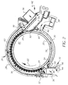
- Fig. 2 is a side elevational view of the heated drum assembly of the processor of Fig. 1.
- Fig. 3 is a perspective view of components of an embodiment of the present invention.
- Fig. 4 is a side elevational view of components of an embodiment of the present invention.
- thermal processor 10 generally includes a heated drum assembly 12 , a film cooling section 14 , densitometer 16 , and airborne contaminant removal system 18 .
- an exposed photothermographic media is heat developed by heated drum assembly 12 .
- the heated media is cooled while passing over cooling section 14 .
- Densitometer 16 reads the density control patches on developed media before the media is output to a user.
- System 18 removes airborne contaminants produced during the heat development process.
- heated drum assembly 12 includes a heated drum 20 which rotates in direction 22 , a plurality of rollers 24 circumferentially arrayed about a segment of drum 20 to hold an exposed media in contact with drum 20 and enclosure 26 enclosing drum 20 and rollers 22 .
- Enclosure 26 includes a first upper curved cover member 28 , spaced from rollers 22 and second lower curved member 30 spaced from and enclosing the lower portion of drum 20 .
- Upper and lower members 28 , 30 have respective first ends 32 , 34 spaced from each other defining a media (film) entrance region 36 and respective second ends 38 , 40 spaced from each other defining a media (film) exit region 42 .
- Film diverter 52 diverts film from contact with rollers 24 to exit over perforated felt pad 54 .
- Top condensation trap 56, bottom condensation trap 58 and top internal duct 60 of member 28 form part of the airborne contaminant removal system of the present invention.
- airflow through heated drum assembly 12 is controlled to remove airborne contaminants produced during image development.
- ambient air is drawn into enclosure 26 at film entrance region 36 .
- Arrows 70 , 72 , 74 denote ambient air input.
- the air is separated into top flow stream 76 and a bottom flow stream 78 separated by film entrance region 36 and film exit region 42 .
- a negative pressure (vacuum) field is applied at the air exit regions to drive flow.
- ambient air splits into two streams moving into the upper and lower regions.
- the top air stream 76 filters air from the pressure roller region and processor cover member. This stream passes above the rollers 24 and out the top internal duct 60 near the film exit region 42 .
- the duct plate 80 between the channel and film exit separates the top air stream 76 to maximize air flow over the rollers 24 and minimize air pulled over the film from the processor film exit which can be a source of image artifacts (location where film loses contact from the drum 20 and starts to rapidly cool).
- a second air stream 78 runs below the drum 20 from the film entrance 36 .
- condensation traps 56 , 58 are designed to trap air contaminants by passing cool ambient air mixed with the hot processor air which causes condensation to occur. After the air is passed through the condensation region, it is further processed by special filter(s) 90 to remove contaminants and odor. Mixing ambient air in the condensation stage cools the air which increases the effectiveness and life of filters 90 . Fan 112 established a negative air pressure to drive the air flows.
- the bottom air stream 78 also aids in uniform temperature development of the film.
- the metal drum 20 operates at a temperature, for example, of approximately 120 + °C and is heated by a circumambient (circumferentially uniform) resistive element heater attached to the drum 20 .
- the film is designed to wrap around the drum 20 a certain length depending on design constraint and 180 degrees can be used. This wrap angle in combination with the drum's rotational velocity and diameter represent the total dwell time needed to adequately develop the film.
- the film generally takes a few seconds to warm up to the drum's operating temperature. This warm-up time typically represents a small percent of total dwell time.
- the film used can draw relatively significant amounts of heat from the drum 20 surface as it first contacts the drum 20 and warms up.
- Circumambient heaters can cause locations of the drum 20 to under heat and over heat when film enters the processor. In locations of early film contact, where the most significant heat load takes place, the drum temperature can decrease while in other locations the drum temperature can increase because it is not loaded as much. The temperature controller does not correct this.
- the drum temperature In a closed loop temperature control setup, the drum temperature can be controlled to a tight temperature variation at a location on the drum, but the overall drum temperature will still vary because of the non-even heat load as the film is applied to the drum. The location where the film does not wrap the drum will have the highest temperature readings. By passing cool air through this location (bottom flow stream 78 ), extra heat can be removed to help make the drum temperature more uniform.
- the lower airflow stream 78 is designed to adjust flow rate depending if film is present. This is done by using the film to block some of the ambient air that mixes in the lower condensation trap. When film is present in the cooling section 14 , the vacuum pressure in the lower duct increases because the ambient air passage is partially blocked. This increases the flow rate of the air in the lower duct, extracting more heat from the lower section of the drum when film is present which balances the drum's heat load better. This also conserves energy when the film is not present since the air flow under the drum 20 is reduced which reduces the duty cycle of the heater.
- the majority of air contaminants are released from the film as it separates from the drum 20 . Strong convective forces are present which lift the gasses.
- airbomed contaminants are removed at duct 60 . Airborne contaminants are further removed a short distance from film diverter 52 with the traps 56 and 58 .
- the condensation traps 56 , 58 are shown in Figs. 3 and 4. Once the airborne contaminants enter the top condensation trap they are mixed with cooler ambient air in chamber 102 to enhance condensation. The insulation 104 of the top condensation trap 56 prevents image artifacts due to temperature gradients. Once the airborne contaminants enter the bottom condensation trap 58 it is mixed with cooler ambient air 106 to enhance condensation. The cooler air 106 flows through a perforated felt pad 54 and short cooling section 108 .
- the top condensation trap 56 and bottom condensation trap 58 are constructed from a thermally conductive material. These traps 56 , 58 are cooled by the ambient air and are attached to the main chassis, which acts as a heat sink.
- the felt perforated pad 54 performs two basic functions 1) structural support as the film is transported along film path 120 and 2) a thermally non-conductive surface. As the film is transported in this region it must be supported because to the film has low beam strength. Film that is not guided may be subjected to stresses that may cause film wrinkles and creases. Film that is cooled rapidly and/or non-uniformly may cause image artifacts.
- the felt pad also acts as a thermal isolator preventing rapid cooling.
- the contaminant removal system requires 7.5 cfm (cubic feet per minute), for example, airflow measured at the fan 112 exhaust.
- the airflow is divided in half through pressure orifices located in the member 114 and the member of respective 116 condensation traps 56 , 58 .
- the airflow is further divided in the condensation traps 50% from the drum outlets and 50% from ambient air. Uniform airflow over the top and under the bottom of the processor drum 20 reduces any temperature gradients.
- the airflow with respect to the perforated felt pad 54 is shown in Fig. 4. As the film travels over the perforated felt pad 54 it blocks the perforated holes and diverts the airflow to the bottom of the drum 20 . This balances the thermal loading of the top and bottom of the drum surface, which decreases drum 20 temperature variations. During idle conditions the air flows through the perforated felt pad 54 mixing cooler air into the condensation traps 56 , 58 .
Landscapes
- Physics & Mathematics (AREA)
- General Physics & Mathematics (AREA)
- Photographic Developing Apparatuses (AREA)
- Non-Silver Salt Photosensitive Materials And Non-Silver Salt Photography (AREA)
Abstract
Description
- This invention relates in general to laser imaging systems and more particularly to a contaminant removal system in a thermal processor of a photothermographic laser imaging system.
- Laser imaging systems are widely used in commercial, industrial, and medical imaging fields. In the medical imaging field, photothermographic laser imaging systems are used to reproduce digital medical images in heat processable photothermographic film. After the film is exposed to a digital medical image, the film is processed by a thermal processor to produce a visual representation of the medical image on the film. The thermal processor includes a rotatable heated drum having circumferentially arrayed pressure rollers to hold the film in contact with the heated drum during development. After development, the film is cooled and output to a user.
- During the heat development process of the exposed photothermographic media, air-borne contaminants are produced that can produce image artifacts in the developed film image. Airflow in the exit region from the drum has resulted in image artifacts that have a Christmas tree type of profile or wispy appearance.
- There is thus a need for improving air contaminant removal in heated drum thermal processors in order to minimize image artifacts in developed film.
- According to the present invention, there is provided a solution to these problems.
- According to an aspect of the present invention there is provided, a thermal processor having a contaminant removal system comprising: a heated drum for heat developing exposed heat developable media which emit air-borne contaminants during said development; a plurality of rollers located about a circumferential segment of said drum to hold an exposed media in contact with said drum; an enclosure for enclosing said heated drum and plurality of rollers, said enclosure including a first upper curved member spaced from and enclosing said rollers and the upper portion of said drum and a second lower curved member spaced from and enclosing said lower portion of said drum, said first and second curved members having first ends spaced from each other and defining a film entrance region, and further having second ends spaced from each other and defining a film exit region; wherein said first upper curved member includes a curved duct having a first opening above said rollers and a second opening configured to direct gaseous fluids away from the film exit from said drum; a top condensation trap communicating with said second opening of said duct; a bottom condensation trap; and an air flow control system for drawing ambient air from outside said enclosure through said film entrance region, splitting said air flow into (a) a top flow stream which passes between said first member over said rollers, through said duct and through said top condensation trap where air-borne contaminants are condensed and said air stream is cooled, and (b) a bottom flow stream which passes between said second member and said lower portion of said drum and through said bottom condensation trap where air-borne contaminants are condensed and said bottom flow stream is cooled.
- The invention has the following advantages.
- 1. Air contaminants produced during development of heat processable exposed media in a heated drum thermal processor are removed in an efficient and cost effective manner.
- 2. Image artifacts are minimized in heat developed exposed media.
- 3. Air temperature is minimized at the filter inlet thus increasing filter life and effectiveness.
-
- Fig. 1 is a perspective view of a heated drum thermal processor incorporating the present invention.
- Fig. 2 is a side elevational view of the heated drum assembly of the processor of Fig. 1.
- Fig. 3 is a perspective view of components of an embodiment of the present invention.
- Fig. 4 is a side elevational view of components of an embodiment of the present invention.
- Referring now to Fig. 1, there is shown a thermal processor incorporating an embodiment of the present invention. As shown,
thermal processor 10 generally includes a heateddrum assembly 12, afilm cooling section 14,densitometer 16, and airbornecontaminant removal system 18. In operation, an exposed photothermographic media is heat developed byheated drum assembly 12. The heated media is cooled while passing overcooling section 14.Densitometer 16 reads the density control patches on developed media before the media is output to a user.System 18 removes airborne contaminants produced during the heat development process. - As shown in greater detail in Fig. 2, heated
drum assembly 12 includes a heateddrum 20 which rotates indirection 22, a plurality ofrollers 24 circumferentially arrayed about a segment ofdrum 20 to hold an exposed media in contact withdrum 20 andenclosure 26 enclosingdrum 20 androllers 22.Enclosure 26 includes a first uppercurved cover member 28, spaced fromrollers 22 and second lowercurved member 30 spaced from and enclosing the lower portion ofdrum 20. Upper andlower members first ends entrance region 36 and respectivesecond ends exit region 42.Feed rollers entrance guides drum 20 underrollers 24. Film diverter 52 diverts film from contact withrollers 24 to exit overperforated felt pad 54.Top condensation trap 56,bottom condensation trap 58 and topinternal duct 60 ofmember 28 form part of the airborne contaminant removal system of the present invention. - According to the present invention, airflow through heated
drum assembly 12 is controlled to remove airborne contaminants produced during image development. In Fig. 2, ambient air is drawn intoenclosure 26 atfilm entrance region 36.Arrows 70, 72, 74 denote ambient air input. The air is separated intotop flow stream 76 and abottom flow stream 78 separated byfilm entrance region 36 andfilm exit region 42. - A negative pressure (vacuum) field is applied at the air exit regions to drive flow. At the film entrance, ambient air splits into two streams moving into the upper and lower regions. The
top air stream 76 filters air from the pressure roller region and processor cover member. This stream passes above therollers 24 and out the topinternal duct 60 near thefilm exit region 42. Theduct plate 80 between the channel and film exit separates thetop air stream 76 to maximize air flow over therollers 24 and minimize air pulled over the film from the processor film exit which can be a source of image artifacts (location where film loses contact from thedrum 20 and starts to rapidly cool). Asecond air stream 78 runs below thedrum 20 from thefilm entrance 36. As the film exits from thedrum 20, airborne contaminants remain on the drum surface and outgas into the lower region. Thelower air stream 78 sweeps out contaminants from that section where potentially high concentrations can exist. At the filtration exit region,condensation traps filters 90. Fan 112 established a negative air pressure to drive the air flows. - The
bottom air stream 78 also aids in uniform temperature development of the film. For heat processable medical film, themetal drum 20 operates at a temperature, for example, of approximately 120 + °C and is heated by a circumambient (circumferentially uniform) resistive element heater attached to thedrum 20. The film is designed to wrap around the drum 20 a certain length depending on design constraint and 180 degrees can be used. This wrap angle in combination with the drum's rotational velocity and diameter represent the total dwell time needed to adequately develop the film. Depending on the heat transfer properties of the different materials involved such as: film material, film thickness, drum material and drum thickness; the film generally takes a few seconds to warm up to the drum's operating temperature. This warm-up time typically represents a small percent of total dwell time. - The film used can draw relatively significant amounts of heat from the
drum 20 surface as it first contacts thedrum 20 and warms up. Circumambient heaters can cause locations of thedrum 20 to under heat and over heat when film enters the processor. In locations of early film contact, where the most significant heat load takes place, the drum temperature can decrease while in other locations the drum temperature can increase because it is not loaded as much. The temperature controller does not correct this. In a closed loop temperature control setup, the drum temperature can be controlled to a tight temperature variation at a location on the drum, but the overall drum temperature will still vary because of the non-even heat load as the film is applied to the drum. The location where the film does not wrap the drum will have the highest temperature readings. By passing cool air through this location (bottom flow stream 78), extra heat can be removed to help make the drum temperature more uniform. - The
lower airflow stream 78 is designed to adjust flow rate depending if film is present. This is done by using the film to block some of the ambient air that mixes in the lower condensation trap. When film is present in thecooling section 14, the vacuum pressure in the lower duct increases because the ambient air passage is partially blocked. This increases the flow rate of the air in the lower duct, extracting more heat from the lower section of the drum when film is present which balances the drum's heat load better. This also conserves energy when the film is not present since the air flow under thedrum 20 is reduced which reduces the duty cycle of the heater. - Air exits the drum regions at the top
internal duct 60 andbottom drum outlet 82. As the film exits the drum, the majority of air contaminants are released from the film as it separates from thedrum 20. Strong convective forces are present which lift the gasses. In this higher concentrated region abovedrum 20, airbomed contaminants are removed atduct 60. Airborne contaminants are further removed a short distance fromfilm diverter 52 with thetraps - The condensation traps 56, 58 are shown in Figs. 3 and 4. Once the airborne contaminants enter the top condensation trap they are mixed with cooler ambient air in
chamber 102 to enhance condensation. Theinsulation 104 of thetop condensation trap 56 prevents image artifacts due to temperature gradients. Once the airborne contaminants enter thebottom condensation trap 58 it is mixed with coolerambient air 106 to enhance condensation. Thecooler air 106 flows through aperforated felt pad 54 andshort cooling section 108. Thetop condensation trap 56 andbottom condensation trap 58 are constructed from a thermally conductive material. Thesetraps - The felt
perforated pad 54 performs two basic functions 1) structural support as the film is transported alongfilm path 120 and 2) a thermally non-conductive surface. As the film is transported in this region it must be supported because to the film has low beam strength. Film that is not guided may be subjected to stresses that may cause film wrinkles and creases. Film that is cooled rapidly and/or non-uniformly may cause image artifacts. The felt pad also acts as a thermal isolator preventing rapid cooling. - The air flows from the
bottom condensation trap 58 through a moldedrubber hose 110 to thetop condensation trap 58 and then to thefiltration system 90. The contaminant removal system requires 7.5 cfm (cubic feet per minute), for example, airflow measured at thefan 112 exhaust. The airflow is divided in half through pressure orifices located in themember 114 and the member of respective 116 condensation traps 56, 58. The airflow is further divided in the condensation traps 50% from the drum outlets and 50% from ambient air. Uniform airflow over the top and under the bottom of theprocessor drum 20 reduces any temperature gradients. - The airflow with respect to the perforated felt
pad 54 is shown in Fig. 4. As the film travels over the perforated feltpad 54 it blocks the perforated holes and diverts the airflow to the bottom of thedrum 20. This balances the thermal loading of the top and bottom of the drum surface, which decreasesdrum 20 temperature variations. During idle conditions the air flows through the perforated feltpad 54 mixing cooler air into the condensation traps 56, 58.
Claims (6)
- A thermal processor having a contaminant removal system comprising:wherein said first upper curved member includes a curved duct having a first opening above said rollers and a second opening configured to direct gaseous fluids away from the film exit from said drum;a heated drum for heat developing exposed heat developable media which emit air-borne contaminants during said development;a plurality of rollers located about a circumferential segment of said drum to hold an exposed media in contact with said drum;an enclosure for enclosing said heated drum and plurality of rollers, said enclosure including a first upper curved member spaced from and enclosing said rollers and the upper portion of said drum and a second lower curved member spaced from and enclosing said lower portion of said drum, said first and second curved members having first ends spaced from each other and defining a film entrance region, and further having second ends spaced from each other and defining a film exit region;
a top condensation trap communicating with said second opening of said duct;
a bottom condensation trap; and
an air flow control system for drawing ambient air from outside said enclosure through said film entrance region, splitting said air flow into (a) a top flow stream which passes between said first member over said rollers, through said duct and through said top condensation trap where airborne contaminants are condensed and said air stream is cooled, and (b) a bottom flow stream which passes between said second member and said lower portion of said drum and through said bottom condensation trap where airborne contaminants are condensed and said bottom flow stream is cooled. - The thermal processor of claim 1 wherein top condensation trap and said bottom condensation trap are connected together to form a continuous path for said top and bottom and air flow streams.
- The thermal processor of claim 1 including a filtration system connected to said traps for filtering said air flow passing through said traps.
- The thermal processor of claim 1 wherein said air flow control system includes an air mover system for creating a negative air pressure to draw air through said air flow system.
- The thermal processor of claim 1 wherein said airflow control system draws ambient air from outside said traps into said traps to cool the air passing through said traps.
- The thermal processor of claim 5 including a film diverter located at said film exit for removing developed film from contact with said heated drum, a perforated felt pad for supporting film after removal from said drum, said pad being in air communication with said bottom condensation trap, wherein when film travels over said felt pad, said perforations are blocked and said airflow is diverted to the bottom of the drum to decrease drum temperature variations.
Applications Claiming Priority (2)
| Application Number | Priority Date | Filing Date | Title |
|---|---|---|---|
| US376547 | 1982-05-10 | ||
| US10/376,547 US6812947B2 (en) | 2003-02-28 | 2003-02-28 | Contaminant removal system in a thermal processor |
Publications (1)
| Publication Number | Publication Date |
|---|---|
| EP1452911A1 true EP1452911A1 (en) | 2004-09-01 |
Family
ID=32771498
Family Applications (1)
| Application Number | Title | Priority Date | Filing Date |
|---|---|---|---|
| EP04075477A Withdrawn EP1452911A1 (en) | 2003-02-28 | 2004-02-16 | Contaminant removal system in a thermal processor |
Country Status (3)
| Country | Link |
|---|---|
| US (1) | US6812947B2 (en) |
| EP (1) | EP1452911A1 (en) |
| JP (1) | JP2004264851A (en) |
Families Citing this family (3)
| Publication number | Priority date | Publication date | Assignee | Title |
|---|---|---|---|---|
| US7064295B1 (en) | 2005-02-10 | 2006-06-20 | Eastman Kodak Company | Thermal processor having flexible duct |
| US20060174409A1 (en) * | 2005-02-10 | 2006-08-10 | Holly Hermanson | Blanket for use during bodyworking or massage |
| KR101404606B1 (en) * | 2007-08-21 | 2014-06-10 | 삼성전자주식회사 | A method of providing menus by using a touchscreen and a multimedia apparatus thereof |
Citations (4)
| Publication number | Priority date | Publication date | Assignee | Title |
|---|---|---|---|---|
| US3757662A (en) * | 1970-01-08 | 1973-09-11 | F Ingels | Apparatus for thermic development of heat-sensitive paper |
| WO1997021150A1 (en) * | 1995-12-04 | 1997-06-12 | Imation Corp. | Photothermographic thermal processor filtration system |
| US5790069A (en) * | 1995-10-06 | 1998-08-04 | Imation Corp. | Thermal Processor with air flow preventing structure |
| US5946025A (en) * | 1997-09-29 | 1999-08-31 | Imation Corp. | Thermal drum processor assembly with roller mounting assembly for a laser imaging device |
Family Cites Families (1)
| Publication number | Priority date | Publication date | Assignee | Title |
|---|---|---|---|---|
| JPH06332142A (en) | 1993-05-20 | 1994-12-02 | Fuji Photo Film Co Ltd | Heat treatment equipment |
-
2003
- 2003-02-28 US US10/376,547 patent/US6812947B2/en not_active Expired - Fee Related
-
2004
- 2004-02-16 EP EP04075477A patent/EP1452911A1/en not_active Withdrawn
- 2004-03-01 JP JP2004055891A patent/JP2004264851A/en not_active Withdrawn
Patent Citations (4)
| Publication number | Priority date | Publication date | Assignee | Title |
|---|---|---|---|---|
| US3757662A (en) * | 1970-01-08 | 1973-09-11 | F Ingels | Apparatus for thermic development of heat-sensitive paper |
| US5790069A (en) * | 1995-10-06 | 1998-08-04 | Imation Corp. | Thermal Processor with air flow preventing structure |
| WO1997021150A1 (en) * | 1995-12-04 | 1997-06-12 | Imation Corp. | Photothermographic thermal processor filtration system |
| US5946025A (en) * | 1997-09-29 | 1999-08-31 | Imation Corp. | Thermal drum processor assembly with roller mounting assembly for a laser imaging device |
Non-Patent Citations (1)
| Title |
|---|
| PATENT ABSTRACTS OF JAPAN vol. 1995, no. 03 28 April 1995 (1995-04-28) * |
Also Published As
| Publication number | Publication date |
|---|---|
| JP2004264851A (en) | 2004-09-24 |
| US20040169714A1 (en) | 2004-09-02 |
| US6812947B2 (en) | 2004-11-02 |
Similar Documents
| Publication | Publication Date | Title |
|---|---|---|
| US6812947B2 (en) | Contaminant removal system in a thermal processor | |
| US11866882B2 (en) | Drain system for a laundry appliance | |
| JP2008166604A (en) | Heating device, coating, developing device and heating method | |
| JP5105396B2 (en) | Heat treatment device | |
| US7510596B2 (en) | Thermal processor with contaminant removal cartridge | |
| JPH11300153A (en) | Sublimation component removal unit and heat treatment apparatus having the same | |
| JP4524896B2 (en) | Tunnel type drying sterilizer | |
| EP1328844A1 (en) | Cooling device in a projector | |
| JPH054659B2 (en) | ||
| US7330200B2 (en) | Thermal processor employing replaceable sleeve | |
| KR19980081473A (en) | Photo Processor | |
| US20100212176A1 (en) | Tumble Dryer With Peltier Heat Pump | |
| US7064295B1 (en) | Thermal processor having flexible duct | |
| CN113286867B (en) | System for removing water from oil | |
| US7087861B2 (en) | Media entrance guide in a thermal processor | |
| JP2003130544A (en) | Drying apparatus and method for drying strip material | |
| JPH10500496A (en) | Filter for photothermographic developing machine | |
| US6979802B2 (en) | Apparatus and method for thermally processing an imaging material employing a preheat chamber | |
| JP2000221658A (en) | Drying equipment for photographic materials | |
| US7317468B2 (en) | Thermal processor employing drum and flatbed technologies | |
| JP2008527411A5 (en) | ||
| JP2004169949A (en) | Drying apparatus | |
| JPH095974A (en) | Automatic processing equipment for photographic photosensitive materials | |
| JPS5669672A (en) | Fixing device | |
| JPH02157093A (en) | Method and apparatus for treatment of photosensitive material |
Legal Events
| Date | Code | Title | Description |
|---|---|---|---|
| PUAI | Public reference made under article 153(3) epc to a published international application that has entered the european phase |
Free format text: ORIGINAL CODE: 0009012 |
|
| AK | Designated contracting states |
Kind code of ref document: A1 Designated state(s): AT BE BG CH CY CZ DE DK EE ES FI FR GB GR HU IE IT LI LU MC NL PT RO SE SI SK TR |
|
| AX | Request for extension of the european patent |
Extension state: AL LT LV MK |
|
| 17P | Request for examination filed |
Effective date: 20050119 |
|
| AKX | Designation fees paid |
Designated state(s): DE FR |
|
| RBV | Designated contracting states (corrected) |
Designated state(s): DE FR |
|
| RAP1 | Party data changed (applicant data changed or rights of an application transferred) |
Owner name: CARESTREAM HEALTH, INC. |
|
| GRAP | Despatch of communication of intention to grant a patent |
Free format text: ORIGINAL CODE: EPIDOSNIGR1 |
|
| STAA | Information on the status of an ep patent application or granted ep patent |
Free format text: STATUS: THE APPLICATION IS DEEMED TO BE WITHDRAWN |
|
| 18D | Application deemed to be withdrawn |
Effective date: 20090321 |