EP1452811A2 - Apparatus and method for the application of evaporators on already formed refrigerator liners - Google Patents
Apparatus and method for the application of evaporators on already formed refrigerator liners Download PDFInfo
- Publication number
- EP1452811A2 EP1452811A2 EP04001911A EP04001911A EP1452811A2 EP 1452811 A2 EP1452811 A2 EP 1452811A2 EP 04001911 A EP04001911 A EP 04001911A EP 04001911 A EP04001911 A EP 04001911A EP 1452811 A2 EP1452811 A2 EP 1452811A2
- Authority
- EP
- European Patent Office
- Prior art keywords
- adhesive substance
- adhesive
- jet
- nozzle
- spray head
- Prior art date
- Legal status (The legal status is an assumption and is not a legal conclusion. Google has not performed a legal analysis and makes no representation as to the accuracy of the status listed.)
- Withdrawn
Links
Images



Classifications
-
- F—MECHANICAL ENGINEERING; LIGHTING; HEATING; WEAPONS; BLASTING
- F25—REFRIGERATION OR COOLING; COMBINED HEATING AND REFRIGERATION SYSTEMS; HEAT PUMP SYSTEMS; MANUFACTURE OR STORAGE OF ICE; LIQUEFACTION SOLIDIFICATION OF GASES
- F25D—REFRIGERATORS; COLD ROOMS; ICE-BOXES; COOLING OR FREEZING APPARATUS NOT OTHERWISE PROVIDED FOR
- F25D23/00—General constructional features
- F25D23/06—Walls
- F25D23/061—Walls with conduit means
-
- B—PERFORMING OPERATIONS; TRANSPORTING
- B05—SPRAYING OR ATOMISING IN GENERAL; APPLYING FLUENT MATERIALS TO SURFACES, IN GENERAL
- B05B—SPRAYING APPARATUS; ATOMISING APPARATUS; NOZZLES
- B05B7/00—Spraying apparatus for discharge of liquids or other fluent materials from two or more sources, e.g. of liquid and air, of powder and gas
- B05B7/02—Spray pistols; Apparatus for discharge
- B05B7/08—Spray pistols; Apparatus for discharge with separate outlet orifices, e.g. to form parallel jets, i.e. the axis of the jets being parallel, to form intersecting jets, i.e. the axis of the jets converging but not necessarily intersecting at a point
- B05B7/0807—Spray pistols; Apparatus for discharge with separate outlet orifices, e.g. to form parallel jets, i.e. the axis of the jets being parallel, to form intersecting jets, i.e. the axis of the jets converging but not necessarily intersecting at a point to form intersecting jets
- B05B7/0861—Spray pistols; Apparatus for discharge with separate outlet orifices, e.g. to form parallel jets, i.e. the axis of the jets being parallel, to form intersecting jets, i.e. the axis of the jets converging but not necessarily intersecting at a point to form intersecting jets with one single jet constituted by a liquid or a mixture containing a liquid and several gas jets
-
- B—PERFORMING OPERATIONS; TRANSPORTING
- B05—SPRAYING OR ATOMISING IN GENERAL; APPLYING FLUENT MATERIALS TO SURFACES, IN GENERAL
- B05C—APPARATUS FOR APPLYING FLUENT MATERIALS TO SURFACES, IN GENERAL
- B05C5/00—Apparatus in which liquid or other fluent material is projected, poured or allowed to flow on to the surface of the work
- B05C5/02—Apparatus in which liquid or other fluent material is projected, poured or allowed to flow on to the surface of the work the liquid or other fluent material being discharged through an outlet orifice by pressure, e.g. from an outlet device in contact or almost in contact, with the work
-
- F—MECHANICAL ENGINEERING; LIGHTING; HEATING; WEAPONS; BLASTING
- F28—HEAT EXCHANGE IN GENERAL
- F28F—DETAILS OF HEAT-EXCHANGE AND HEAT-TRANSFER APPARATUS, OF GENERAL APPLICATION
- F28F1/00—Tubular elements; Assemblies of tubular elements
- F28F1/10—Tubular elements and assemblies thereof with means for increasing heat-transfer area, e.g. with fins, with projections, with recesses
- F28F1/12—Tubular elements and assemblies thereof with means for increasing heat-transfer area, e.g. with fins, with projections, with recesses the means being only outside the tubular element
- F28F1/14—Tubular elements and assemblies thereof with means for increasing heat-transfer area, e.g. with fins, with projections, with recesses the means being only outside the tubular element and extending longitudinally
- F28F1/22—Tubular elements and assemblies thereof with means for increasing heat-transfer area, e.g. with fins, with projections, with recesses the means being only outside the tubular element and extending longitudinally the means having portions engaging further tubular elements
-
- F—MECHANICAL ENGINEERING; LIGHTING; HEATING; WEAPONS; BLASTING
- F25—REFRIGERATION OR COOLING; COMBINED HEATING AND REFRIGERATION SYSTEMS; HEAT PUMP SYSTEMS; MANUFACTURE OR STORAGE OF ICE; LIQUEFACTION SOLIDIFICATION OF GASES
- F25B—REFRIGERATION MACHINES, PLANTS OR SYSTEMS; COMBINED HEATING AND REFRIGERATION SYSTEMS; HEAT PUMP SYSTEMS
- F25B39/00—Evaporators; Condensers
- F25B39/02—Evaporators
- F25B39/022—Evaporators with plate-like or laminated elements
- F25B39/024—Evaporators with plate-like or laminated elements with elements constructed in the shape of a hollow panel
-
- F—MECHANICAL ENGINEERING; LIGHTING; HEATING; WEAPONS; BLASTING
- F28—HEAT EXCHANGE IN GENERAL
- F28F—DETAILS OF HEAT-EXCHANGE AND HEAT-TRANSFER APPARATUS, OF GENERAL APPLICATION
- F28F2275/00—Fastening; Joining
- F28F2275/02—Fastening; Joining by using bonding materials; by embedding elements in particular materials
- F28F2275/025—Fastening; Joining by using bonding materials; by embedding elements in particular materials by using adhesives
Definitions
- the present invention refers to an apparatus and a method concerning a production technology used in manufacturing household-type refrigerators provided with a so-called "concealed"-type evaporator, i.e. an evaporator that is not arranged inside the storage or refrigerating compartment of the refrigerator, but is rather provided on the outside of the same compartment and, therefore, generally embedded in the thermally insulating material surrounding the compartment itself.
- a so-called "concealed"-type evaporator i.e. an evaporator that is not arranged inside the storage or refrigerating compartment of the refrigerator, but is rather provided on the outside of the same compartment and, therefore, generally embedded in the thermally insulating material surrounding the compartment itself.
- Household-type refrigerators provided with a refrigerating or cold storage compartment and a concealed-type evaporator are largely known in the art.
- the liner that delimitates this cold storage compartment in these appliances is made of thermoformed plastic material, typically a sheet of polystyrene, and is thermally insulated from the outside by means of a layer of thermally insulating material, usually polyurethane, that is applied on the outside of the same liner by means of a largely known foaming process.
- the latter is made out of a roll-bond plate that is applied onto the outer surface of said liner prior to foaming, in such a manner that, after foaming, said roll-bond plate is practically embedded in said layer of foamed insulating material and is held captive, i.e. trapped between said same layer and the liner, so as to ensure the desired heat-exchange relation.
- bi-adhesive material and the thickness thereof, are of course selected so as to by all means avoid impairing the close heat-exchange relation being required in this particular application.
- this method shall be capable of being easily implemented and carried out with the use of existing techniques and must ensure the required constancy of the heat-exchange condition between the evaporator plate and the liner.
- top-priority targets i.e. the targets that had imperatively to be reached by starting a research work dedicated to such an object, were as follows:
- a method has therefore been eventually found and selected on this basis, which substantially enables the afore cited aims and targets to be reached, and whose basic feature, distinguishing it at least partly from prior-art techniques, lies substantially in the fact that the adhesive is not applied with the aid of a support means that is subsequently removed (by way of example, much in the same manner of an adhesive plate or label), but is rather deposited directly onto the surface to be treated by spraying it thereupon by means of one or more appropriate spray heads, in which there are arranged both a nozzle issuing a thin jet of previously prepared liquid adhesive, and a plurality of nozzles issuing respective jets of air, said nozzles being situated in close vicinity of said adhesive jet and oriented so as to hit, and therefore atomise, said adhesive jet, thereby substantially converting it into an emission which is very similar to a very fine and, for the matter, practically atomised open spray.
- the liners 1 Prior to foaming for thermal insulation, the liners 1 are arranged orderly, with their backside facing upwards, on a continuously moving conveyance means 2, usually consisting of a sliding slat or apron conveyer, which carries said liners 1 under a spray head 3 in an orderly sequence.
- a continuously moving conveyance means 2 usually consisting of a sliding slat or apron conveyer, which carries said liners 1 under a spray head 3 in an orderly sequence.
- This spray head is provided and arranged so as to be able to displace along three orthogonal axes Y, Y and Z, in which on the axis X there are represented the vertical displacements made in relation to said conveyance means 2 (as a result, in the case of liners of the same type, i.e. having similar dimensions, there will be no displacement of said head along the axis X).
- Said spray head 3 is then driven so as to move on a horizontal plane along two axes Y and Z by means of an arm 4 connecting said head 3 to a first member 5 that enables it to slide horizontally along a direction Z extending orthogonally to the direction of displacement of the apron conveyor, said first member being in turn connected to a second member 6 enabling again the head to slide horizontally, however in a direction Y that is parallel to the direction of displacement of the apron conveyor 1.
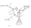
- Said terminal emission plate 14 is in turn provided with at least a preferably central nozzle 19, adapted to issue said adhesive substance, as well as a plurality of nozzles 23 for issuing air under pressure with such a flow orientation as to be able to cause the jet of adhesive substance to be atomised.
- this comprises also a machine 20 for preparing, heating up, liquefying, putting under pressure and pumping the adhesive substance; it further includes a control unit 21 for generating and transmitting appropriate sequences of synchronized control signals adapted to at least control the operation of the driving means of said first member 5 and said second member 6 which determine the position of the arm 4, which in turn supports said spray head 3.
- slat or apron conveyor 2 which displaces in the direction indicated by the arrow, there is arranged a sequence of regularly spaced liners 1 following each other in an orderly row, in which the surface 8 to be treated of said liners 1 is so oriented as to face upwards.
- spray head 3 Above said surfaces, at a certain distance therefrom, there is arranged the spray head 3, the latter being fitted out as described above.
- This spray head is driven to displace along the two axes X and Z by means of corresponding movements imparted, with the aid of generally known means (not shown), to said second member 6 and said first member 5.
- said arm 4 is slidably connected to said first sliding member 5 with the aid of appropriate means (not shown, but generally identified at H in the Figure), said first member being in turn slidably linked to said second sliding member 6, again with the aid of means that are not shown, but generally situated at K in the Figure.
- the machine 20 for the preparation of the adhesive substance lets a flow of said adhesive substance into the conduit 12, through which it then reaches the nozzle 19 of the plate 14, which however keeps in its closed state owing to the electromagnetic valve 15 on the spray head 3 being closed, so that said adhesive substance is put under pressure upstream of said electromagnetic valve.
- the electromagnetic valve 15 on the spray head 3 is opened, so that a thin continuous jet of adhesive substance is able to issue, directed downwards, from the nozzle 19 of the terminal plate 14.
- said terminal plate is also provided with the compressed-air conduits 23 arranged in the close vicinity of the adhesive-emitting nozzle 19, and owing to these conduits being oriented obliquely downwards, the effect thereof is to cause the filament of adhesive substance issuing from said nozzle 19 to practically atomise and, ultimately, to produce an atomised jet of adhesive substance onto the surface 8 of the liners.
- the spray head 3 is displaced in a controlled manner so as to move along the axes Y and Z repeatedly, i.e. to perform more passages along said axes, as long as each surface 8 dwells therebelow, so that the atomised jet of adhesive is capable of spreading over the surface with the desired evenness and according to the desired distribution pattern, so as this is for instance illustrated symbolically in Figure 1.
- said jet of atomised adhesive substance tends to affect a pre-determined portion A of the surface of the liner, as well as to settle according to a pre-established geometry, i.e. pattern, on said surface to be treated, so that it is actually the pre-established areas of said surface that are substantially covered by said adhesive substance to a pre-determined, fully controllable extent.
- both the flow of adhesive substance and the jets of air issuing from said emission plate 14 are heated up immediately prior to being emitted from said plate and, to this purpose, the afore cited respective heating elements 16, 17 are appropriately energized with means and in manners that are largely known in the art.
- the actual size of the jet of adhesive is a critical factor. It has been found that the ejection of the adhesive should ideally occur from a nozzle, the outlet port of which must have a diameter comprised between 0.35 and 0.50 mm.
- the optimum size of the jet when the latter hits and deposits onto the surface to be treated, corresponds to a width that should not lie below 3 mm.
- these may be constituted by an adhesive application machine of the type NORDSON 3830V, capable of ensuring the above-indicated process parameters or adapted to be controlled, set or programmed so as to ensure them.
- a basic aim was to measure the adhesiveness, under peel (90x) and shear stress, of the two bonding methods, both directly on the involved items and, in view of a better and more comprehensive assessment, on appropriately prepared specimens.
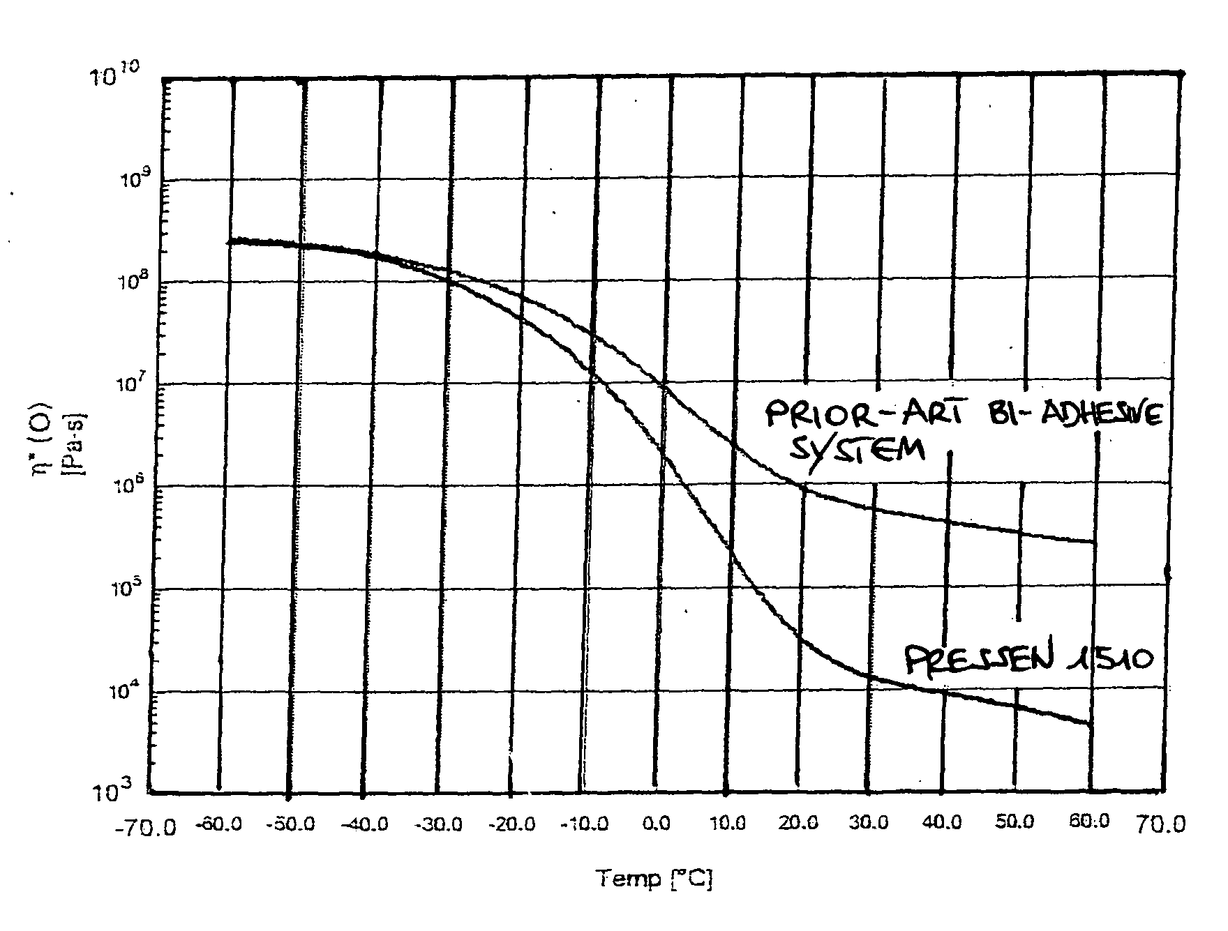
- the viscosity of the two systems has been measured as a function of temperature.
- the afore-cited hot-melt adhesive Pressen shows a lower viscosity than the prior-art bi-adhesive system starting already from as low a temperature as -40°C.
- Such a difference then tends to become larger and larger, until it reaches a really significant extent at temperatures above 0°C.
- This fact while proving favourable at low temperatures, makes the hot-melt adhesive far less resistant at high ambient temperatures.
- the hot-melt adhesive does not give rise to any evaporator-liner detachment problem at the low temperatures. What on the contrary must be most carefully considered is the compromise between the low viscosity at high temperature - which allows for working with lower pressures on the bonding machine - and the relative adhesiveness - with the afore cited poor adhesiveness at the higher temperatures - especially in view of the stresses which the assembly may be subject to prior to foaming.
Landscapes
- Engineering & Computer Science (AREA)
- Physics & Mathematics (AREA)
- Mechanical Engineering (AREA)
- Thermal Sciences (AREA)
- General Engineering & Computer Science (AREA)
- Chemical & Material Sciences (AREA)
- Combustion & Propulsion (AREA)
- Geometry (AREA)
- Application Of Or Painting With Fluid Materials (AREA)
- Adhesives Or Adhesive Processes (AREA)
- Spray Control Apparatus (AREA)
Abstract
Description
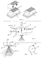
- Figure 1 is a symbolical view of the coverage pattern of strips of adhesive substance on an outer surface of the liner of a refrigerator appliance, according to the method of the present invention;
- Figure 2 is a perspective view of the layout schematics of an apparatus according to the present invention;
- Figure 3 is a symbolical top view of an apparatus according to the present invention;
- Figure 4 is a perspective view of a sub-assembly of the apparatus shown in the preceding Figures;
- Figure 5 is a symbolical view of the functional schematics of the sub-assembly of Figure 4;
- Figure 6 is a symbolical, see-through view of the functional schematics of a second sub-assembly of an apparatus according to the present invention;
- Figure 7 is a bottom view of a detail of the nozzle comprised in the sub-assembly of Figure 4;
- Figure 8 is a schematical view of the phase in which the jet of adhesive substance issuing from the nozzle of Figure 7 is cast and dispersed (atomised);
- Figure 9 is a view of a liner treated with an adhesive deposition method according to the present invention, immediately prior to and after the application of a related evaporator.
- possibility for a method to be found which was capable of being fully automated,
- possibility for such a method to be integrated in a continuous cycle of sequential production,
- reduction of production costs,
- absence of any permanent deformation or distortion of the liner during the evaporator assembly phase,
- high reliability and simplicity of the method,
- highest safety and low environmental impact,
- uniform coverage or, anyway, coverage capable of satisfactorily meeting the given requirements.
- a
central body 11, - a
conduit 12 to deliver the adhesive substance, - a
conduit 13 to deliver a flow of air to atomising purposes, - a
terminal emission plate 14, - an
electromagnetic valve 15 to control saidconduit 12, - two
independent heating elements supply cables - a
control cable 18 associated to saidelectromagnetic valve 15.
- the adhesive substance used in the method has general properties similar to those of the product normally available on the market under the type designation PRESSEN 1510, the main properties of which are indicated in Table A;
- this adhesive substance is pre-heated to a temperature situated anywhere between 140°C and 170°C, and is ejected from the spray head at such a temperature;
- this adhesive substance is then distributed over and deposited onto the surface to be treated through the ejection from a related nozzle of a continuous filament that is atomised soon upon leaving said nozzle;
- the jet of atomised adhesive substance must be deposited onto the surface to be treated in an amount ranging from 130 to 220 g/m2;
- the rate at which said filament is ejected from the nozzle shall be comprised between 100 and 200 mm/sec;
- the distance from said
terminal emission plate 14 to the underlying surface to be covered must be comprised between 5 and 8 cm.

Claims (10)
- Method, adapted to be carried out also manually, for the application of an evaporator, in particular with a side thereof lying on a plane, onto the outer surface (8) of a liner (1) delimitating internally the food storage compartment of a refrigerator appliance, comprising a phase in which adhesive means are interposed between said outer surface (8) and the evaporator, characterized in that said interposition of adhesive means includes:the ejection of a jet of semi-liquid adhesive substance from a proper nozzle comprised in a spray head, facing said surface (8), but lying at a distance therefrom, and the conversion of said semi-liquid jet into an atomised spray prior to hitting said surface, so that the latter is invested by said atomised ejection and is covered in a selective manner with a substantially uniform layer of said adhesive substance.
- Method according to claim 1, characterized in that said conversion of a jet of adhesive substance into an atomised spray is carried out by investing said jet with at least a proper forced flow of gas, preferably ambient air, immediately downstream of said ejection nozzle, so that said jet is broken up into an atomised spray directed against said outer surface (8).
- Method according to claim 1 or 2, characterized in that said adhesive substance is distributed on said surface to an amount by weight situated anywhere between 130 and 220 g/m2.
- Method according to any of the preceding claims, characterized in that said nozzle issuing said jet of adhesive substance is kept at a distance of 5 to 8 cm from said outer surface.
- Method according to any of the preceding claims, characterized in that the temperature at which said semi-liquid adhesive substance leaves the ejection nozzle is situated anywhere between 140°C and 170°C.
- Method according to any of the preceding claims, characterized in that the time needed by said atomised spray to cover said surface is less than 30 seconds when the surface being treated has an area of 30 dm2.
- Apparatus for the emission and deposition of a flow of adhesive substance onto a preferably planar surface, in particular onto a surface of a liner of a refrigerator appliance, characterized in that it comprises at least one of following elements or a combination thereof:a spray head (3),a machine (20) for preparing the adhesive substance and delivering it under pressure to said spray head (3).
- Apparatus according to claim 7, characterized in that said spray head (3) comprises:a conduit (12) delivering said adhesive substance,a second conduit (13) delivering a flow of gas under pressure,an electromagnetic valve (15) controlling said adhesive-substance delivering conduit (12) terminating in a first nozzle (19),one or more other nozzles (23) arranged in close proximity of said first nozzle (19) and adapted to convey said flow of gas towards the ejection zone of said first nozzle so as to intercept the jet of adhesive substance issuing therefrom, in which said first nozzle (19) and said further nozzles (23) are possibly provided in the form of through-holes in an emission plate (14) arranged on the lower side of said head (3).
- Apparatus according to claim 8, characterized in that it further comprises:means (2) to orderly conveying said liners below said spray head,further means (4, 5, 6) that are at least partly capable of being selectively positioned and displaced above said conveyance means (2), and are slidably connected also to said spray head (3),a control unit (21) adapted to control the position and the displacements of said further means (4, 5, 6).
- Apparatus according to any of the preceding claims 7 to 9, characterized in that said spray head (3) also comprises two independent heating elements (16, 17) adapted to selectively heat up said flow of adhesive substance and said flow of gas.
Applications Claiming Priority (2)
| Application Number | Priority Date | Filing Date | Title |
|---|---|---|---|
| ITPN20030016 | 2003-02-28 | ||
| ITPN20030016 ITPN20030016A1 (en) | 2003-02-28 | 2003-02-28 | SYSTEM AND PROCEDURE FOR APPLICATION OF FORMED CELL EVAPORATOR. |
Publications (2)
| Publication Number | Publication Date |
|---|---|
| EP1452811A2 true EP1452811A2 (en) | 2004-09-01 |
| EP1452811A3 EP1452811A3 (en) | 2004-12-01 |
Family
ID=32750518
Family Applications (1)
| Application Number | Title | Priority Date | Filing Date |
|---|---|---|---|
| EP04001911A Withdrawn EP1452811A3 (en) | 2003-02-28 | 2004-01-29 | Apparatus and method for the application of evaporators on already formed refrigerator liners |
Country Status (3)
| Country | Link |
|---|---|
| EP (1) | EP1452811A3 (en) |
| IT (1) | ITPN20030016A1 (en) |
| RU (1) | RU2264587C1 (en) |
Cited By (2)
| Publication number | Priority date | Publication date | Assignee | Title |
|---|---|---|---|---|
| CN105127048A (en) * | 2014-05-27 | 2015-12-09 | 珠海格力电器股份有限公司 | evaporator sealing device |
| WO2023031091A1 (en) * | 2021-09-01 | 2023-03-09 | Liebherr-Hausgeräte Lienz Gmbh | Method for arranging an electric or electronic component on a cooling and/or freezing device |
Families Citing this family (2)
| Publication number | Priority date | Publication date | Assignee | Title |
|---|---|---|---|---|
| DE102008009786A1 (en) * | 2008-02-19 | 2009-08-20 | BSH Bosch und Siemens Hausgeräte GmbH | Refrigerating appliance, method and apparatus for its production |
| ITMI20102368A1 (en) * | 2010-12-22 | 2012-06-23 | Indesit Co Spa | METHOD OF PREPARATION OF A THERMOPLASTIC ITEM AND ITEM PREPARED WITH THIS METHOD |
Family Cites Families (8)
| Publication number | Priority date | Publication date | Assignee | Title |
|---|---|---|---|---|
| US2795035A (en) * | 1955-08-03 | 1957-06-11 | Revco Inc | Method of making a refrigerated cabinet liner |
| US3744921A (en) * | 1971-05-07 | 1973-07-10 | Cooper Ind Inc | Glue gun construction |
| US3871188A (en) * | 1973-09-07 | 1975-03-18 | Thermo King Corp | Demountable transportation refrigeration unit |
| US4024620A (en) * | 1974-02-22 | 1977-05-24 | Environmental Container Corporation | Methods for manufacturing refrigerating systems |
| US4113152A (en) * | 1977-03-14 | 1978-09-12 | Schmidt Robert W | Adhesive dispensing device |
| SU1730516A1 (en) * | 1990-02-26 | 1992-04-30 | Специальное Конструкторское Бюро По Бытовым Холодильникам И Компрессорам Донецкого Производственного Объединения "Электробытмаш" | Refrigerator |
| US6210141B1 (en) * | 1998-02-10 | 2001-04-03 | Nordson Corporation | Modular die with quick change die tip or nozzle |
| JP4529060B2 (en) * | 2000-10-20 | 2010-08-25 | ノードソン株式会社 | Apparatus and method for applying liquid to a sheet-like object |
-
2003
- 2003-02-28 IT ITPN20030016 patent/ITPN20030016A1/en unknown
-
2004
- 2004-01-29 EP EP04001911A patent/EP1452811A3/en not_active Withdrawn
- 2004-02-27 RU RU2004106689/12A patent/RU2264587C1/en not_active IP Right Cessation
Cited By (2)
| Publication number | Priority date | Publication date | Assignee | Title |
|---|---|---|---|---|
| CN105127048A (en) * | 2014-05-27 | 2015-12-09 | 珠海格力电器股份有限公司 | evaporator sealing device |
| WO2023031091A1 (en) * | 2021-09-01 | 2023-03-09 | Liebherr-Hausgeräte Lienz Gmbh | Method for arranging an electric or electronic component on a cooling and/or freezing device |
Also Published As
| Publication number | Publication date |
|---|---|
| RU2264587C1 (en) | 2005-11-20 |
| EP1452811A3 (en) | 2004-12-01 |
| RU2004106689A (en) | 2005-08-10 |
| ITPN20030016A1 (en) | 2004-09-01 |
Similar Documents
| Publication | Publication Date | Title |
|---|---|---|
| US3995075A (en) | Inside stripe by intermittent exterior spray guns | |
| US8293035B2 (en) | Treatment method, system and product | |
| CN100393428C (en) | Coating method and system for forming protective layer | |
| US20090107398A1 (en) | Fluid dispensers and methods for dispensing viscous fluids with improved edge definition | |
| RU2010124425A (en) | SPRAYED CHOCOLATE GLAZES WITH REDUCED FAT | |
| US20040224086A1 (en) | Automated hot melt application apparatus and method | |
| US20100209615A1 (en) | Method and System for Applying Hot Melt Adhesive Powder onto a Non-Metallic Surface | |
| EP2506981A2 (en) | Coaxial laser assisted cold spray nozzle | |
| US20140131463A1 (en) | Self-cleaning spray valve assembly | |
| CN114260350B (en) | Hot forming method for galvanized sheet | |
| RU2264587C1 (en) | Method of mounting evaporator on refrigerator facing | |
| CA2546533C (en) | Coating method | |
| KR100824699B1 (en) | Nozzles for silicone melt spraying and glue guns using them | |
| CA2230418C (en) | Mechanism and process for coating threaded articles having varying external configurations | |
| CN207357482U (en) | A kind of ultrasonic atomization coating apparatus | |
| US20040164460A1 (en) | Method for producing an article of plastics by injection molding | |
| CN217855998U (en) | Color sand spraying and granulating device | |
| JP5428298B2 (en) | How to decorate repair structures | |
| US20190203345A1 (en) | Molten material supply unit and dry coating device comprising same | |
| EP2162560A2 (en) | Metallization device and method | |
| JP2025010934A (en) | Curtain-like spray coating device and coating method | |
| US8707716B1 (en) | Re-circulating defrosting heat exchanger | |
| JP5329790B2 (en) | Method and apparatus for applying liquid, absorbent article and method for manufacturing the same | |
| JP2011015629A (en) | Discharge device | |
| CN106929803B (en) | Film coated plastic production equipment and its production method |
Legal Events
| Date | Code | Title | Description |
|---|---|---|---|
| PUAI | Public reference made under article 153(3) epc to a published international application that has entered the european phase |
Free format text: ORIGINAL CODE: 0009012 |
|
| AK | Designated contracting states |
Kind code of ref document: A2 Designated state(s): AT BE BG CH CY CZ DE DK EE ES FI FR GB GR HU IE IT LI LU MC NL PT RO SE SI SK TR |
|
| AX | Request for extension of the european patent |
Extension state: AL LT LV MK |
|
| PUAL | Search report despatched |
Free format text: ORIGINAL CODE: 0009013 |
|
| AK | Designated contracting states |
Kind code of ref document: A3 Designated state(s): AT BE BG CH CY CZ DE DK EE ES FI FR GB GR HU IE IT LI LU MC NL PT RO SE SI SK TR |
|
| AX | Request for extension of the european patent |
Extension state: AL LT LV MK |
|
| 17P | Request for examination filed |
Effective date: 20050526 |
|
| AKX | Designation fees paid |
Designated state(s): AT BE BG CH CY CZ DE DK EE ES FI FR GB GR HU IE IT LI LU MC NL PT RO SE SI SK TR |
|
| 17Q | First examination report despatched |
Effective date: 20081219 |
|
| STAA | Information on the status of an ep patent application or granted ep patent |
Free format text: STATUS: THE APPLICATION IS DEEMED TO BE WITHDRAWN |
|
| 18D | Application deemed to be withdrawn |
Effective date: 20090430 |