EP1452735A2 - Compressor valve plate - Google Patents
Compressor valve plate Download PDFInfo
- Publication number
- EP1452735A2 EP1452735A2 EP03256361A EP03256361A EP1452735A2 EP 1452735 A2 EP1452735 A2 EP 1452735A2 EP 03256361 A EP03256361 A EP 03256361A EP 03256361 A EP03256361 A EP 03256361A EP 1452735 A2 EP1452735 A2 EP 1452735A2
- Authority
- EP
- European Patent Office
- Prior art keywords
- valve plate
- center
- plate assembly
- spacer
- compressor
- Prior art date
- Legal status (The legal status is an assumption and is not a legal conclusion. Google has not performed a legal analysis and makes no representation as to the accuracy of the status listed.)
- Granted
Links
- 125000006850 spacer group Chemical group 0.000 claims abstract description 50
- 230000006835 compression Effects 0.000 claims description 35
- 238000007906 compression Methods 0.000 claims description 35
- 238000005057 refrigeration Methods 0.000 claims description 9
- 235000014676 Phragmites communis Nutrition 0.000 description 12
- 238000007789 sealing Methods 0.000 description 7
- 239000012530 fluid Substances 0.000 description 3
- 238000005452 bending Methods 0.000 description 1
- 230000036316 preload Effects 0.000 description 1
- 239000007787 solid Substances 0.000 description 1
- 239000011800 void material Substances 0.000 description 1
Images


Classifications
-
- F—MECHANICAL ENGINEERING; LIGHTING; HEATING; WEAPONS; BLASTING
- F04—POSITIVE - DISPLACEMENT MACHINES FOR LIQUIDS; PUMPS FOR LIQUIDS OR ELASTIC FLUIDS
- F04B—POSITIVE-DISPLACEMENT MACHINES FOR LIQUIDS; PUMPS
- F04B39/00—Component parts, details, or accessories, of pumps or pumping systems specially adapted for elastic fluids, not otherwise provided for in, or of interest apart from, groups F04B25/00 - F04B37/00
- F04B39/10—Adaptations or arrangements of distribution members
-
- F—MECHANICAL ENGINEERING; LIGHTING; HEATING; WEAPONS; BLASTING
- F04—POSITIVE - DISPLACEMENT MACHINES FOR LIQUIDS; PUMPS FOR LIQUIDS OR ELASTIC FLUIDS
- F04B—POSITIVE-DISPLACEMENT MACHINES FOR LIQUIDS; PUMPS
- F04B39/00—Component parts, details, or accessories, of pumps or pumping systems specially adapted for elastic fluids, not otherwise provided for in, or of interest apart from, groups F04B25/00 - F04B37/00
- F04B39/10—Adaptations or arrangements of distribution members
- F04B39/1066—Valve plates
Definitions
- the present invention relates generally to refrigeration compressors. More particularly, the present invention relates to a reciprocating piston type refrigeration compressor which incorporates a unique design for the valve plate assembly which improves the clamping characteristics of the valve plate gasket and thus improves the sealing of the valve plate gasket.
- Reciprocating piston type compressors typically employ suction and discharge pressure actuated valving mounted onto a valve plate assembly which is located at the end of a cylinder formed by a compressor body.
- the valve plate assembly fifteen typically sandwiched between a compressor head and the compressor body.
- a valve plate gasket is located between the valve plate assembly and the compressor body to seal the interface.
- valve plate gasket is compressed due to a clamping load which is created by the attachment of the compressor head to the compressor body.
- the compressor head is attached to the compressor body by head bolts which extend through the compressor head, through the head gasket, through the valve plate assembly through the valve plate gasket and finally threadingly received by the compressor body. As these head bolts are tightened, compression of the valve plate gasket occurs.
- the head bolts are located around the outside perimeter of the compressor head, the valve plate assembly and the valve plate gasket.
- the valve plate gasket receives most of its clamping load from this outside perimeter. Because the clamping load is generated at the outside perimeter of the valve plate gasket, there is a lower clamping load and thus a lower amount of compression of the valve plate gasket in the center portion of the valve plate gasket spaced from the outside perimeter. Because of this lower amount of compression of the valve plate gasket in the center portion, most of the valve plate gasket failures occur in this center portion.
- valve plate gasket compression load is also created by the high pressure discharge gas located above the valve plate assembly.
- This high pressure discharge gas presses the valve plate assembly against the valve plate gasket and the compressor body.
- the valve plate assembly is comprised of an upper valve plate, a lower valve plate and one or more spacers located between the upper and lower valve plates.
- the load, exerted by the high pressure discharge gas is exerted on the upper valve plate and this exerted pressure is not transmitted directly to the lower valve plate in this center portion.
- the present invention provides the art with a unique valve plate assembly which improves the valve gasket clamping load in the center portion and thus it significantly reduces valve gasket failures.
- the unique valve plate assembly of the present invention includes a center spacer which is located between the upper and lower valve plates in the center portion of the valve plate assembly. By incorporating this additional center spacer, the valve plate assembly exerts an increased clamping force in this center portion to increase the compression of the valve plate gasket and thus improve its performance and durability.
- the center spacer defines a bolt hole which extends through the spacer.
- a center bolt is assembled through the valve plate assembly using this bolt hole and it is threadingly received by the compressor body. When this center bolt is tightened, it provides additional clamping load to the valve plate gasket in the center portion to produce a more even clamping load throughout the entire valve plate gasket to improve performance and durability while reducing failures.
- the center bolt can extend only through the valve plate assembly and through the valve plate gasket into the compressor body or the center bolt can extend through the compressor head, through the valve plate assembly and through the valve plate gasket into the compressor body if desired.
- the center spacer does not include the bolt hole.
- the center spacer is located within the center portion of the valve plate assembly to transmit both the clamping load and the pressure exerted by the high pressure discharge gas from the upper valve plate, to the lower valve plate, to the valve plate gasket and finally to the compressor body.
- This additional load exerted onto the valve plate gasket at its center portion increases the compression of the gasket at the center portion to produce a more even clamping load throughout the entire valve plate gasket to improve performance and durability while reducing failures.
- This additional embodiment is useful when it is not possible to assemble a center bolt due to a compressor unloader system or other features of the compressor being located at a position which limits access to the center portion of the valve plate assembly.
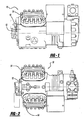
- Figure 1 is a side view of a compressor assembly incorporating the unique valve plate assembly in accordance with the present invention
- Figure 2 is a top view of the compressor assembly illustrated in Figure 1;
- Figure 3 is a partial cross-sectional view through the compressor assembly illustrated in Figure 1 and 2 where each cylinder is shown rotated 90° about a central axis;
- Figure 4 is a top plan view of the unique valve plate assembly illustrated in Figure 1-3;
- Figure 5 is a side cross-sectional view of the unique valve plate assembly illustrated in Figure 4.
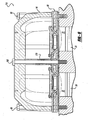
- Figure 6 is a partial cross-sectional view similar to Figure 3 through a compressor assembly in accordance with another embodiment of the present invention.
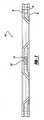
- Figure 7 is a side cross-sectional view of a unique valve plate assembly in accordance with another embodiment of the present invention.
- Compressor assembly 10 which incorporates the unique valve plate assembly in accordance with the present invention.
- Compressor assembly 10 comprises a compressor body 12, a compressor head 14, a head gasket 16, a valve plate assembly 18 and a valve plate gasket 20.
- Compressor body 12 defines a pair of compression cylinders 22 within which a piston 24 is slidably disposed.
- Each compression cylinder 22 is in communication with both a discharge chamber and a suction chamber through valve plate assembly 18.
- Valve plate assembly 18 comprises an upper valve plate 26, a lower valve plate 28, an annular spacer 30 a plurality of interior spacers 32 and a center spacer 34.
- Valve plate assembly 18 defines a pair of suction passages 36 which are in communication with the suction chamber of compression assembly 10 and a pair of discharge passages 38 which are in communication with the discharge chamber of compressor assembly 10.
- Each discharge passage 38 is defined by a radially inclined or beveled sidewall 40 extending between an upper surface 42 and a lower surface 44 of valve plate assembly 18.
- Beveled sidewall 40 is formed from upper valve plate 26.
- a surface 46 of beveled sidewall 40 provides a valve seat for a discharge valve member 48 which is urged into sealing engagement therewith by discharge gas pressure and a spring 50 extending between discharge valve member 48 and a bridge-like retainer 52.
- discharge valve member 48 is of a size and a shape relative to discharge passage 38 so as to place a lower surface 54 thereof in substantially coplanar relationship to lower surface 44 of valve plate assembly 18.
- Spring 50 is located in a recess 56 provided in retainer 52.
- Discharge valve member 48 is essentially pressure actuated and spring 50 is chosen primarily to provide stability and also to provide an initial closing bias or preload to establish an initial seal. Other types of springs, other than that illustrated may of course be used for this purpose.
- Retainer 52 which also serves as a stop to limit the opening movement of valve member 48 is secured to valve plate assembly 18 by a pair of suitable fasteners 58.
- Annular spacer 30 is disposed between upper valve plate 26 and lower valve plate 28 and annular spacer 30 forms suction passage 36 with upper valve plate 26 and lower valve plate 28.
- the plurality of interior spacers 32 are positioned around each compression cylinder 22 as illustrated in Figure 4.
- Valve plate assembly 18 is secured to compressor body 12 when compressor head 14 is secured to compressor body 12.
- Valve plate assembly 18 is sandwiched between compressor head 14 and compressor body 12 with valve plate gasket 20 being sandwiched between valve plate assembly 18 and compressor body 12 and head gasket 16 being sandwiched between valve plate assembly 18 and compressor head 14.
- a plurality of bolts 60 extend through compressor head 14, head gasket 16, upper valve plate 26 of valve plate assembly 18, annular spacer 30 of valve plate assembly 18, lower valve plate 28 of valve plate assembly 18, valve plate gasket 20 and are threadingly received by compressor body 12.
- the tightening of bolts 60 compresses valve plate gasket 20 to provide a sealing relationship between valve plate assembly 18 and compressor body 12 provide a sealing relationship between valve plate assembly 18 and compressor head 14.
- the plurality of bolts 60 and annular spacer 30 of valve plate assembly 18 are located around the outer circumferential portion of compressor head 14 and valve plate assembly 18.
- valve plate gasket 20 extending through compressor head 14, head gasket 16, valve plate assembly 18, valve plate gasket 20 and threadingly received by compressor body 12 were the only mechanical means for providing a compressive load to valve plate gasket 20. While this compressive load was sufficient for the outer circumferential portion of valve plate gasket 20 , the center portion of valve plate gasket 20 would see less of a compressive load than the outer circumferential portion due to the distance between the center portion and each of the plurality of bolts 60.
- the present invention improves the compressive characteristics of valve plate gasket 20 and thus its performance and durability by adding center spacer 34.
- Center spacer 34 is located at approximately the geometric center of valve plate assembly 18 at a position which is on a line which extends between the geometric center of one compression cylinder 22 and the geometric center of an adjacent compression cylinder 22. This places center spacer 34 generally midway between both the length and width of valve plate assembly 18.
- Center spacer 34 extends between upper valve plate 26 and lower valve plate 28 and is received within a bore 62 defined by lower valve plate 28. While illustrated as being received in bore 62 in lower valve plate 28, bore 62 could be located in upper valve plate 26 and center spacer 34 could be reversed from what is illustrated if desired.
- Center spacer 34 defines a through hole 64 which is aligned with a hole 66 extending through upper valve plate 26.
- a center bolt 68 extends through hole 66 of upper valve plate 26, through hole 64 of center spacer 34 and is threadingly received in compressor body 12. The tightening of center bolt 68 provides additional compressive load for valve plate gasket 20 at the center of valve plate gasket 20 to increase the compression of valve plate gasket 20, to produce a more even clamping load throughout the entire valve plate gasket 20 and to improve both the performance and durability of its sealing function.
- Valve plate assembly 18 further defines an annular valve seat 70 and sidewall 40 defines an annular valve seat 72 located at its terminal end. Disposed between valve seat 70 and valve seat 72 is suction passage 36.
- Valve seat 72 of sidewall 40 is positioned in coplanar relationship with valve seat 70 of valve plate assembly 18.
- a suction reed valve member 76 in the form of an annular ring sealingly engages, in its closed position, valve seat 72 of sidewall 40 and valve seat 70 of valve plate assembly 18 to prevent passage of fluid from compression cylinder 22 into suction passage 36.
- a central opening 78 is provided in suction reed valve member 76 and is arranged coaxially with discharge passage 38 so as to allow direct fluid flow communication between compression cylinder 22 and lower surface 54 of discharge valve member 48.
- Suction reed valve member 76 also includes a pair of diametrically opposed radially outwardly extending tabs 80. One tab 80 is used to secure reed valve member 76 to valve plate assembly 18 using a pair of drive studs 82.
- suction reed valve member 76 As piston 24 within compression cylinder 22 moves away from valve plate assembly 18 during a suction stroke, the pressure differential between compression cylinder 22 and suction passage 36 will cause suction reed valve member 76 to deflect inwardly with respect to compression cylinder 22, to its open position (shown in dashed lines in Figure 3), thereby enabling gas flow from suction passage 36 into compression cylinder 22 between valve seats 70 and 72. Because only tabs 80 of suction reed valve member 76 extend outwardly beyond the sidewalls of compression cylinder 22, suction fluid flow will readily flow into compression cylinder 22 around substantially the entire inner and outer peripheries of suction reed valve member 76.
- valve plate assembly 18 and reed valve member 76 allow substantially the entire available surface area overlying compression cylinder 22 to be utilized for suction and discharge valving and porting, thereby allowing maximum gas flow both into and out of compression cylinder 22.
- Compressor body 12 includes an angled or curved portion 84 at the outer edge of compression cylinder 22 adjacent the free end of suction reed valve member 76 to provide a friendly surface for suction reed valve member 76 to bend against, thereby significantly reducing the bending stresses generated within the free end tab 80.
- FIG. 6 a compressor assembly 110 in accordance with another embodiment of the present invention is illustrated.
- the embodiment illustrated in Figure 6 is the same as the embodiment illustrated in Figure 3 except that center bolt 68 has been replaced by center bolt 168.
- Center bolt 68 extended through valve plate assembly 18 and valve plate gasket 20 and was threadingly received by compressor body 12.
- Center bolt 168 illustrated in Figure 6 extends through cylinder head 14, valve plate assembly 18 and valve plate gasket 20 and is threadingly received by compressor body 12.
- an extension 170 is added to cylinder head 14 through which center bolt 168 extends.
- the operation, function and features of compressive assembly 110 are the same as those described above for compressor assembly 10.
- Valve plate assembly 118 is the same as valve plate assembly 18 except that center spacer 34 has been replaced with center spacer 134.
- Center spacer 134 is located at the same position as center spacer 34 which is at approximately the geometric center of valve plate assembly 118. This places center spacer 134 generally midway between both the length and width of valve plate assembly 118 or the same position as shown for center spacer 34 in Figure 4.
- Center spacer 134 extends between upper valve plate 26 and lower valve plate 28 and is received within a bore 162 defined by upper valve plate 26. While illustrated as being received in bore 162 in upper valve plate 26, bore 162 could be located in lower valve plate 28 and center spacer 134 could be reversed from what is illustrated if desired.
- center spacer 134 is a solid member, center bolt 68 or 168 are not included and thus valve plate gasket 20 does not receive additional compression at its center portion through the tightening of a center bolt. Instead, the additional compressive load applied to the center portion of valve plate gasket 20 is applied by the addition of a center rib similar to extension 170 illustrated in Figure 6 and by gas pressure from compressed gas which is located in the gas discharge chamber located above valve plate assembly 118. Compressed gas at discharge pressure exerts a load on upper valve plate 26 and this load is transferred directly to lower valve plate 28 through center spacer 134. In addition, the tightening of bolts 60 exert a load on upper valve plate 26 through the center rib (not shown) and this load is also transferred directly to lower valve plate 28 through center spacer 134.
- valve plate gasket 20 The exerted load on lower valve plate 28 is then exerted on valve plate gasket 20 to provide additional compressive load for valve plate gasket 20 at the center of valve plate gasket 20 to increase the compression of valve plate gasket 20, to produce a more even clamping load throughout the entire valve plate gasket 20 and to improve both the performance and durability of its sealing function.
- center spacer 134 the pressure load exerted on upper valve plate 26 is not directly transferred to lower valve plate 28.
Landscapes
- Engineering & Computer Science (AREA)
- Mechanical Engineering (AREA)
- General Engineering & Computer Science (AREA)
- Compressor (AREA)
- Check Valves (AREA)
Abstract
Description
- The present invention relates generally to refrigeration compressors. More particularly, the present invention relates to a reciprocating piston type refrigeration compressor which incorporates a unique design for the valve plate assembly which improves the clamping characteristics of the valve plate gasket and thus improves the sealing of the valve plate gasket.
- Reciprocating piston type compressors typically employ suction and discharge pressure actuated valving mounted onto a valve plate assembly which is located at the end of a cylinder formed by a compressor body. The valve plate assembly fifteen typically sandwiched between a compressor head and the compressor body. A valve plate gasket is located between the valve plate assembly and the compressor body to seal the interface.
- Traditionally, the valve plate gasket is compressed due to a clamping load which is created by the attachment of the compressor head to the compressor body. The compressor head is attached to the compressor body by head bolts which extend through the compressor head, through the head gasket, through the valve plate assembly through the valve plate gasket and finally threadingly received by the compressor body. As these head bolts are tightened, compression of the valve plate gasket occurs.
- Typically, the head bolts are located around the outside perimeter of the compressor head, the valve plate assembly and the valve plate gasket. Thus, the valve plate gasket receives most of its clamping load from this outside perimeter. Because the clamping load is generated at the outside perimeter of the valve plate gasket, there is a lower clamping load and thus a lower amount of compression of the valve plate gasket in the center portion of the valve plate gasket spaced from the outside perimeter. Because of this lower amount of compression of the valve plate gasket in the center portion, most of the valve plate gasket failures occur in this center portion.
- In addition to compression of the valve plate gasket by the head bolts, valve plate gasket compression load is also created by the high pressure discharge gas located above the valve plate assembly. This high pressure discharge gas presses the valve plate assembly against the valve plate gasket and the compressor body. Typically the valve plate assembly is comprised of an upper valve plate, a lower valve plate and one or more spacers located between the upper and lower valve plates. In the center area of the valve plate assembly, there is no head bolt as described above and thus there is no spacer which creates an open void due to the lack of a spacer between the upper and lower valve plates. This means that the load, exerted by the high pressure discharge gas, is exerted on the upper valve plate and this exerted pressure is not transmitted directly to the lower valve plate in this center portion.
- The present invention provides the art with a unique valve plate assembly which improves the valve gasket clamping load in the center portion and thus it significantly reduces valve gasket failures. The unique valve plate assembly of the present invention includes a center spacer which is located between the upper and lower valve plates in the center portion of the valve plate assembly. By incorporating this additional center spacer, the valve plate assembly exerts an increased clamping force in this center portion to increase the compression of the valve plate gasket and thus improve its performance and durability.
- In the first embodiment of the present invention, the center spacer defines a bolt hole which extends through the spacer. A center bolt is assembled through the valve plate assembly using this bolt hole and it is threadingly received by the compressor body. When this center bolt is tightened, it provides additional clamping load to the valve plate gasket in the center portion to produce a more even clamping load throughout the entire valve plate gasket to improve performance and durability while reducing failures. The center bolt can extend only through the valve plate assembly and through the valve plate gasket into the compressor body or the center bolt can extend through the compressor head, through the valve plate assembly and through the valve plate gasket into the compressor body if desired.
- In another embodiment of the present invention, the center spacer does not include the bolt hole. The center spacer is located within the center portion of the valve plate assembly to transmit both the clamping load and the pressure exerted by the high pressure discharge gas from the upper valve plate, to the lower valve plate, to the valve plate gasket and finally to the compressor body. This additional load exerted onto the valve plate gasket at its center portion increases the compression of the gasket at the center portion to produce a more even clamping load throughout the entire valve plate gasket to improve performance and durability while reducing failures. This additional embodiment is useful when it is not possible to assemble a center bolt due to a compressor unloader system or other features of the compressor being located at a position which limits access to the center portion of the valve plate assembly.
- Further areas of applicability of the present invention will become apparent from the detailed description provided hereinafter. It should be understood that the detailed description and specific examples, while indicating the preferred embodiment of the invention, are intended for purposes of illustration only and are not intended to limit the scope of the invention.
- The present invention will become more fully understood from the detailed description and the accompanying drawings, wherein:
- Figure 1 is a side view of a compressor assembly incorporating the unique valve plate assembly in accordance with the present invention;
- Figure 2 is a top view of the compressor assembly illustrated in Figure 1;
- Figure 3 is a partial cross-sectional view through the compressor assembly illustrated in Figure 1 and 2 where each cylinder is shown rotated 90° about a central axis;
- Figure 4 is a top plan view of the unique valve plate assembly illustrated in Figure 1-3;
- Figure 5 is a side cross-sectional view of the unique valve plate assembly illustrated in Figure 4.
- Figure 6 is a partial cross-sectional view similar to Figure 3 through a compressor assembly in accordance with another embodiment of the present invention; and
- Figure 7 is a side cross-sectional view of a unique valve plate assembly in accordance with another embodiment of the present invention.
- The following description of the preferred embodiment(s) is merely exemplary in nature and is in no way intended to limit the invention, its application, or uses. There is shown in Figures 1-5 and
compressor assembly 10 which incorporates the unique valve plate assembly in accordance with the present invention.Compressor assembly 10 comprises acompressor body 12, acompressor head 14, a head gasket 16, avalve plate assembly 18 and a valve plate gasket 20. -
Compressor body 12 defines a pair ofcompression cylinders 22 within which apiston 24 is slidably disposed. Eachcompression cylinder 22 is in communication with both a discharge chamber and a suction chamber throughvalve plate assembly 18. -
Valve plate assembly 18 comprises anupper valve plate 26, alower valve plate 28, an annular spacer 30 a plurality ofinterior spacers 32 and acenter spacer 34.Valve plate assembly 18 defines a pair ofsuction passages 36 which are in communication with the suction chamber ofcompression assembly 10 and a pair ofdischarge passages 38 which are in communication with the discharge chamber ofcompressor assembly 10. Eachdischarge passage 38 is defined by a radially inclined orbeveled sidewall 40 extending between anupper surface 42 and alower surface 44 ofvalve plate assembly 18.Beveled sidewall 40 is formed fromupper valve plate 26. Asurface 46 ofbeveled sidewall 40 provides a valve seat for a discharge valve member 48 which is urged into sealing engagement therewith by discharge gas pressure and aspring 50 extending between discharge valve member 48 and a bridge-like retainer 52. - As shown, discharge valve member 48 is of a size and a shape relative to
discharge passage 38 so as to place alower surface 54 thereof in substantially coplanar relationship tolower surface 44 ofvalve plate assembly 18.Spring 50 is located in a recess 56 provided inretainer 52. Discharge valve member 48 is essentially pressure actuated andspring 50 is chosen primarily to provide stability and also to provide an initial closing bias or preload to establish an initial seal. Other types of springs, other than that illustrated may of course be used for this purpose.Retainer 52, which also serves as a stop to limit the opening movement of valve member 48 is secured tovalve plate assembly 18 by a pair of suitable fasteners 58. -
Annular spacer 30 is disposed betweenupper valve plate 26 andlower valve plate 28 andannular spacer 30forms suction passage 36 withupper valve plate 26 andlower valve plate 28. The plurality ofinterior spacers 32 are positioned around eachcompression cylinder 22 as illustrated in Figure 4.Valve plate assembly 18 is secured tocompressor body 12 whencompressor head 14 is secured tocompressor body 12.Valve plate assembly 18 is sandwiched betweencompressor head 14 andcompressor body 12 with valve plate gasket 20 being sandwiched betweenvalve plate assembly 18 andcompressor body 12 and head gasket 16 being sandwiched betweenvalve plate assembly 18 andcompressor head 14. - A plurality of
bolts 60 extend throughcompressor head 14, head gasket 16,upper valve plate 26 ofvalve plate assembly 18,annular spacer 30 ofvalve plate assembly 18,lower valve plate 28 ofvalve plate assembly 18, valve plate gasket 20 and are threadingly received bycompressor body 12. The tightening ofbolts 60 compresses valve plate gasket 20 to provide a sealing relationship betweenvalve plate assembly 18 andcompressor body 12 provide a sealing relationship betweenvalve plate assembly 18 andcompressor head 14. As shown in the Figures, the plurality ofbolts 60 andannular spacer 30 ofvalve plate assembly 18 are located around the outer circumferential portion ofcompressor head 14 andvalve plate assembly 18. In the prior art, the plurality ofbolts 60 extending throughcompressor head 14, head gasket 16,valve plate assembly 18, valve plate gasket 20 and threadingly received bycompressor body 12 were the only mechanical means for providing a compressive load to valve plate gasket 20. While this compressive load was sufficient for the outer circumferential portion of valve plate gasket 20 , the center portion of valve plate gasket 20 would see less of a compressive load than the outer circumferential portion due to the distance between the center portion and each of the plurality ofbolts 60. - The present invention improves the compressive characteristics of valve plate gasket 20 and thus its performance and durability by adding
center spacer 34.Center spacer 34 is located at approximately the geometric center ofvalve plate assembly 18 at a position which is on a line which extends between the geometric center of onecompression cylinder 22 and the geometric center of anadjacent compression cylinder 22. Thisplaces center spacer 34 generally midway between both the length and width ofvalve plate assembly 18.Center spacer 34 extends betweenupper valve plate 26 andlower valve plate 28 and is received within abore 62 defined bylower valve plate 28. While illustrated as being received inbore 62 inlower valve plate 28, bore 62 could be located inupper valve plate 26 andcenter spacer 34 could be reversed from what is illustrated if desired.Center spacer 34 defines a throughhole 64 which is aligned with ahole 66 extending throughupper valve plate 26. A center bolt 68 extends throughhole 66 ofupper valve plate 26, throughhole 64 ofcenter spacer 34 and is threadingly received incompressor body 12. The tightening of center bolt 68 provides additional compressive load for valve plate gasket 20 at the center of valve plate gasket 20 to increase the compression of valve plate gasket 20, to produce a more even clamping load throughout the entire valve plate gasket 20 and to improve both the performance and durability of its sealing function. -
Valve plate assembly 18 further defines anannular valve seat 70 andsidewall 40 defines anannular valve seat 72 located at its terminal end. Disposed betweenvalve seat 70 andvalve seat 72 issuction passage 36. -
Valve seat 72 ofsidewall 40 is positioned in coplanar relationship withvalve seat 70 ofvalve plate assembly 18. A suction reed valve member 76 in the form of an annular ring sealingly engages, in its closed position,valve seat 72 ofsidewall 40 andvalve seat 70 ofvalve plate assembly 18 to prevent passage of fluid fromcompression cylinder 22 intosuction passage 36. Acentral opening 78 is provided in suction reed valve member 76 and is arranged coaxially withdischarge passage 38 so as to allow direct fluid flow communication betweencompression cylinder 22 andlower surface 54 of discharge valve member 48. Suction reed valve member 76 also includes a pair of diametrically opposed radially outwardly extendingtabs 80. Onetab 80 is used to secure reed valve member 76 tovalve plate assembly 18 using a pair ofdrive studs 82. - As
piston 24 withincompression cylinder 22 moves away fromvalve plate assembly 18 during a suction stroke, the pressure differential betweencompression cylinder 22 andsuction passage 36 will cause suction reed valve member 76 to deflect inwardly with respect tocompression cylinder 22, to its open position (shown in dashed lines in Figure 3), thereby enabling gas flow fromsuction passage 36 intocompression cylinder 22 betweenvalve seats only tabs 80 of suction reed valve member 76 extend outwardly beyond the sidewalls ofcompression cylinder 22, suction fluid flow will readily flow intocompression cylinder 22 around substantially the entire inner and outer peripheries of suction reed valve member 76. As a compression stroke ofpiston 24 begins, suction reed valve member 76 will be forced into sealing engagement withvalve seat 70 andvalve seat 72. Discharge valve member 48 will begin to open due to the pressure withincompression cylinder 22 exceeding the pressure withindischarge passage 38 and the force exerted byspring 50. The compressed gas will be forced throughcentral opening 78, past discharge valve member 48 and intodischarge passage 38. The concentric arrangement ofvalve plate assembly 18 and reed valve member 76 allow substantially the entire available surface area overlyingcompression cylinder 22 to be utilized for suction and discharge valving and porting, thereby allowing maximum gas flow both into and out ofcompression cylinder 22. - The continuous stroking of
piston 24 withincompression cylinder 22 continuously causes suction reed valve member 76 and discharge valve member 48 to move between their open and closed positions.Compressor body 12 includes an angled orcurved portion 84 at the outer edge ofcompression cylinder 22 adjacent the free end of suction reed valve member 76 to provide a friendly surface for suction reed valve member 76 to bend against, thereby significantly reducing the bending stresses generated within thefree end tab 80. - Referring now to Figure 6, a compressor assembly 110 in accordance with another embodiment of the present invention is illustrated. The embodiment illustrated in Figure 6 is the same as the embodiment illustrated in Figure 3 except that center bolt 68 has been replaced by
center bolt 168. Center bolt 68 extended throughvalve plate assembly 18 and valve plate gasket 20 and was threadingly received bycompressor body 12.Center bolt 168 illustrated in Figure 6 extends throughcylinder head 14,valve plate assembly 18 and valve plate gasket 20 and is threadingly received bycompressor body 12. In order to exert the addition compressive loads, anextension 170 is added tocylinder head 14 through whichcenter bolt 168 extends. The operation, function and features of compressive assembly 110 are the same as those described above forcompressor assembly 10. - Referring now to Figure 7, a
valve plate assembly 118 in accordance with another embodiment of the present invention is illustrated.Valve plate assembly 118 is the same asvalve plate assembly 18 except that center spacer 34 has been replaced withcenter spacer 134.Center spacer 134 is located at the same position ascenter spacer 34 which is at approximately the geometric center ofvalve plate assembly 118. This placescenter spacer 134 generally midway between both the length and width ofvalve plate assembly 118 or the same position as shown forcenter spacer 34 in Figure 4.Center spacer 134 extends betweenupper valve plate 26 andlower valve plate 28 and is received within abore 162 defined byupper valve plate 26. While illustrated as being received inbore 162 inupper valve plate 26, bore 162 could be located inlower valve plate 28 andcenter spacer 134 could be reversed from what is illustrated if desired. - Because
center spacer 134 is a solid member,center bolt 68 or 168 are not included and thus valve plate gasket 20 does not receive additional compression at its center portion through the tightening of a center bolt. Instead, the additional compressive load applied to the center portion of valve plate gasket 20 is applied by the addition of a center rib similar toextension 170 illustrated in Figure 6 and by gas pressure from compressed gas which is located in the gas discharge chamber located abovevalve plate assembly 118. Compressed gas at discharge pressure exerts a load onupper valve plate 26 and this load is transferred directly tolower valve plate 28 throughcenter spacer 134. In addition, the tightening ofbolts 60 exert a load onupper valve plate 26 through the center rib (not shown) and this load is also transferred directly tolower valve plate 28 throughcenter spacer 134. The exerted load onlower valve plate 28 is then exerted on valve plate gasket 20 to provide additional compressive load for valve plate gasket 20 at the center of valve plate gasket 20 to increase the compression of valve plate gasket 20, to produce a more even clamping load throughout the entire valve plate gasket 20 and to improve both the performance and durability of its sealing function. In the prior art wherecenter spacer 134 is not present, the pressure load exerted onupper valve plate 26 is not directly transferred tolower valve plate 28. - The description of the invention is merely exemplary in nature and, thus, variations that do not depart from the scope of the invention as defined by the claims are intended to be included.
Claims (8)
- A refrigeration compressor comprisinga compressor body defining a first and a second compression cylinder;a compressor head attached to said compressor body; anda valve plate assembly disposed between said compressor head and said compressor body, said valve plate assembly comprising:an upper valve plate;a lower valve plate;an annular spacer disposed between said upper and said lower valve plate, and annular spacer surrounding said first and second compression cylinders; anda center spacer disposed between said upper and said lower valve plate, said center spacer being located between said first and said second compression cylinders.
- The refrigeration compressor according to claim 1, wherein said center spacer defines a through bore.
- The refrigeration compressor according to claim 1, wherein said center spacer defines a through bore concentric with a hole extending through said top plate and a hole extending through said bottom plate.
- The refrigeration compressor according to claim 3, further comprising a bolt extending through said hole in said top plate, through said hole in said top plate, through said through bore and through said hole in said bottom plate, said bolt being threadingly received by said compressor body.
- The refrigeration compressor according to any one of the preceding claims, wherein said center spacer is disposed within a hole defined by said upper valve plate.
- The refrigeration compressor according to any one of the preceding claims, wherein said center spacer is disposed on a line which extends between a geometric center of said first compression cylinder and a geometric center of said second compression cylinder.
- The refrigeration compressor according to any one of the preceding claims, wherein said center spacer is located at approximately the geometric center of said valve plate assembly.
- A compressor comprising a valve plate assembly itself comprising a center spacer which causes said valve plate assembly to compress a valve plate gasket near the center thereof.
Applications Claiming Priority (2)
| Application Number | Priority Date | Filing Date | Title |
|---|---|---|---|
| US10/374,385 US7040877B2 (en) | 2003-02-25 | 2003-02-25 | Compressor valve plate |
| US374385 | 2003-02-25 |
Publications (3)
| Publication Number | Publication Date |
|---|---|
| EP1452735A2 true EP1452735A2 (en) | 2004-09-01 |
| EP1452735A3 EP1452735A3 (en) | 2006-05-17 |
| EP1452735B1 EP1452735B1 (en) | 2018-12-05 |
Family
ID=32771444
Family Applications (1)
| Application Number | Title | Priority Date | Filing Date |
|---|---|---|---|
| EP03256361.1A Expired - Lifetime EP1452735B1 (en) | 2003-02-25 | 2003-10-09 | Compressor valve plate |
Country Status (10)
| Country | Link |
|---|---|
| US (2) | US7040877B2 (en) |
| EP (1) | EP1452735B1 (en) |
| JP (1) | JP2004257374A (en) |
| KR (1) | KR100991710B1 (en) |
| CN (2) | CN100480509C (en) |
| AR (1) | AR041844A1 (en) |
| BR (1) | BR0304779B1 (en) |
| CA (1) | CA2444082C (en) |
| MX (1) | MXPA04001581A (en) |
| TW (1) | TWI223052B (en) |
Cited By (1)
| Publication number | Priority date | Publication date | Assignee | Title |
|---|---|---|---|---|
| WO2007070999A1 (en) * | 2005-12-22 | 2007-06-28 | Whirlpool S.A. | Compact compressor |
Families Citing this family (18)
| Publication number | Priority date | Publication date | Assignee | Title |
|---|---|---|---|---|
| US7040877B2 (en) * | 2003-02-25 | 2006-05-09 | Copeland Corporation | Compressor valve plate |
| JP4758728B2 (en) * | 2005-10-25 | 2011-08-31 | サンデン株式会社 | Reciprocating fluid machine |
| CN102155387A (en) * | 2007-10-02 | 2011-08-17 | 艾默生环境优化技术有限公司 | Compressor having improved valve plate |
| CN101915327A (en) * | 2010-08-25 | 2010-12-15 | 吕文孝 | Control valve for heat flow instrument |
| DE102015015177A1 (en) | 2014-12-22 | 2016-06-23 | Gea Bock Gmbh | compressor |
| US10436187B2 (en) * | 2015-10-29 | 2019-10-08 | Emerson Climate Technologies, Inc. | Cylinder head assembly for reciprocating compressor |
| US10920762B2 (en) | 2016-05-07 | 2021-02-16 | Emerson Climate Technologies, Inc. | Cylinder head assembly for a reciprocating compressor including a cylinder head with an integral valve plate |
| US10315495B2 (en) | 2016-06-30 | 2019-06-11 | Emerson Climate Technologies, Inc. | System and method of controlling compressor, evaporator fan, and condenser fan speeds during a battery mode of a refrigeration system for a container of a vehicle |
| US10328771B2 (en) | 2016-06-30 | 2019-06-25 | Emerson Climated Technologies, Inc. | System and method of controlling an oil return cycle for a refrigerated container of a vehicle |
| US10562377B2 (en) | 2016-06-30 | 2020-02-18 | Emerson Climate Technologies, Inc. | Battery life prediction and monitoring |
| US10569620B2 (en) | 2016-06-30 | 2020-02-25 | Emerson Climate Technologies, Inc. | Startup control systems and methods to reduce flooded startup conditions |
| US10300766B2 (en) | 2016-06-30 | 2019-05-28 | Emerson Climate Technologies, Inc. | System and method of controlling passage of refrigerant through eutectic plates and an evaporator of a refrigeration system for a container of a vehicle |
| US10532632B2 (en) | 2016-06-30 | 2020-01-14 | Emerson Climate Technologies, Inc. | Startup control systems and methods for high ambient conditions |
| US10414241B2 (en) | 2016-06-30 | 2019-09-17 | Emerson Climate Technologies, Inc. | Systems and methods for capacity modulation through eutectic plates |
| US10828963B2 (en) | 2016-06-30 | 2020-11-10 | Emerson Climate Technologies, Inc. | System and method of mode-based compressor speed control for refrigerated vehicle compartment |
| EP4438899A3 (en) * | 2016-11-23 | 2024-12-04 | PSG Germany GmbH | Membrane pump |
| CN110905769B (en) * | 2019-12-11 | 2021-10-26 | 珠海格力节能环保制冷技术研究中心有限公司 | Exhaust valve assembly, compressor and household appliance |
| KR102752770B1 (en) * | 2020-02-19 | 2025-01-14 | 한온시스템 주식회사 | Scroll compressor |
Citations (1)
| Publication number | Priority date | Publication date | Assignee | Title |
|---|---|---|---|---|
| US4470774A (en) | 1981-11-04 | 1984-09-11 | Copeland Corporation | Valve plate assembly for refrigeration compressors |
Family Cites Families (28)
| Publication number | Priority date | Publication date | Assignee | Title |
|---|---|---|---|---|
| US886045A (en) * | 1906-03-06 | 1908-04-28 | Herman J Ehrlich | Valve. |
| US1852033A (en) * | 1925-11-25 | 1932-04-05 | Frigidaire Corp | Check valve |
| US1834589A (en) * | 1927-12-29 | 1931-12-01 | Sullivan Machinery Co | Valve mechanism |
| NL249720A (en) * | 1959-03-23 | 1900-01-01 | ||
| AT350702B (en) * | 1976-10-06 | 1979-06-11 | Enfo Grundlagen Forschungs Ag | LAMELLA VALVE FOR PISTON COMPRESSORS |
| US4478243A (en) * | 1978-12-20 | 1984-10-23 | Copeland Corporation | Valve assembly |
| US4368755A (en) * | 1978-12-20 | 1983-01-18 | Copeland Corporation | Valve assembly |
| US4445534A (en) * | 1980-12-23 | 1984-05-01 | Copeland Corporation | Valve assembly |
| US4469126A (en) * | 1981-11-04 | 1984-09-04 | Copeland Corporation | Discharge valve assembly for refrigeration compressors |
| US4548234A (en) * | 1981-11-04 | 1985-10-22 | Copeland Corporation | Discharge valve assembly |
| US4543989A (en) * | 1981-11-04 | 1985-10-01 | Copeland Corporation | Discharge valve assembly for refrigeration compressors |
| US4643139A (en) * | 1983-07-20 | 1987-02-17 | Hargreaves Bernard J | Reed valves for internal combustion engines |
| US4642037A (en) * | 1984-03-08 | 1987-02-10 | White Consolidated Industries, Inc. | Reed valve for refrigeration compressor |
| US4696263A (en) * | 1985-07-12 | 1987-09-29 | Performance Industries, Inc. | Reed valves for internal combustion engines |
| US4729402A (en) * | 1986-08-01 | 1988-03-08 | Copeland Corporation | Compressor valve noise attenuation |
| DE3721464A1 (en) * | 1987-06-30 | 1989-01-12 | Wabco Westinghouse Fahrzeug | STOP FOR A COMPRESSOR LAMBER VALVE |
| US5022833A (en) * | 1989-12-06 | 1991-06-11 | Tecumseh Products Company | Single piece gasket valve plate assembly |
| US5016669A (en) * | 1990-06-04 | 1991-05-21 | Dresser-Rand Company | Valve assembly |
| BR9002787A (en) * | 1990-06-08 | 1991-12-10 | Brasil Compressores Sa | VALVE FOR HERMETIC COMPRESSOR |
| EP0491026B1 (en) * | 1990-07-10 | 1995-03-01 | Westonbridge International Limited | Valve, method for producing said valve and micropump incorporating said valve |
| US5213487A (en) * | 1991-06-26 | 1993-05-25 | Holset Engineering Company, Inc. | Ring valve type air compressor with deformable ring valves |
| US5213125A (en) * | 1992-05-28 | 1993-05-25 | Thomas Industries Inc. | Valve plate with a recessed valve assembly |
| US5934305A (en) * | 1996-09-12 | 1999-08-10 | Samsung Electronics Co., Ltd. | Method of manufacturing a reciprocating compressor |
| US6044832A (en) | 1998-08-10 | 2000-04-04 | Piersons, Jr.; Donald W. | Fall away arrow rest assembly |
| US6044862A (en) * | 1999-02-16 | 2000-04-04 | Copeland Corporation | Compressor reed valve |
| US6164334A (en) * | 1999-04-27 | 2000-12-26 | Copeland Corporation | Reed valve retention |
| JP2001032774A (en) | 1999-07-22 | 2001-02-06 | Mitsubishi Electric Corp | Valve device for reciprocating refrigerant compressor |
| US7040877B2 (en) * | 2003-02-25 | 2006-05-09 | Copeland Corporation | Compressor valve plate |
-
2003
- 2003-02-25 US US10/374,385 patent/US7040877B2/en not_active Expired - Lifetime
- 2003-10-07 CA CA2444082A patent/CA2444082C/en not_active Expired - Fee Related
- 2003-10-08 TW TW092127993A patent/TWI223052B/en not_active IP Right Cessation
- 2003-10-08 KR KR1020030069857A patent/KR100991710B1/en not_active Expired - Lifetime
- 2003-10-09 EP EP03256361.1A patent/EP1452735B1/en not_active Expired - Lifetime
- 2003-10-28 BR BRPI0304779-2A patent/BR0304779B1/en not_active IP Right Cessation
- 2003-10-28 AR ARP030103932A patent/AR041844A1/en active IP Right Grant
- 2003-11-05 JP JP2003375063A patent/JP2004257374A/en active Pending
- 2003-12-09 CN CNB200610092497XA patent/CN100480509C/en not_active Expired - Fee Related
- 2003-12-09 CN CNB2003101202214A patent/CN1270088C/en not_active Expired - Lifetime
-
2004
- 2004-02-20 MX MXPA04001581A patent/MXPA04001581A/en active IP Right Grant
-
2006
- 2006-04-07 US US11/400,809 patent/US7618244B2/en not_active Expired - Lifetime
Patent Citations (1)
| Publication number | Priority date | Publication date | Assignee | Title |
|---|---|---|---|---|
| US4470774A (en) | 1981-11-04 | 1984-09-11 | Copeland Corporation | Valve plate assembly for refrigeration compressors |
Cited By (1)
| Publication number | Priority date | Publication date | Assignee | Title |
|---|---|---|---|---|
| WO2007070999A1 (en) * | 2005-12-22 | 2007-06-28 | Whirlpool S.A. | Compact compressor |
Also Published As
| Publication number | Publication date |
|---|---|
| CN1525067A (en) | 2004-09-01 |
| TW200416372A (en) | 2004-09-01 |
| AR041844A1 (en) | 2005-06-01 |
| KR20040076567A (en) | 2004-09-01 |
| US7040877B2 (en) | 2006-05-09 |
| BR0304779B1 (en) | 2012-03-20 |
| TWI223052B (en) | 2004-11-01 |
| CA2444082C (en) | 2010-12-21 |
| EP1452735A3 (en) | 2006-05-17 |
| US20060177331A1 (en) | 2006-08-10 |
| BR0304779A (en) | 2005-05-17 |
| CA2444082A1 (en) | 2004-08-25 |
| AU2004200755A1 (en) | 2004-09-09 |
| US20040166006A1 (en) | 2004-08-26 |
| CN1270088C (en) | 2006-08-16 |
| KR100991710B1 (en) | 2010-11-03 |
| CN100480509C (en) | 2009-04-22 |
| CN1896514A (en) | 2007-01-17 |
| JP2004257374A (en) | 2004-09-16 |
| EP1452735B1 (en) | 2018-12-05 |
| MXPA04001581A (en) | 2004-08-30 |
| US7618244B2 (en) | 2009-11-17 |
Similar Documents
| Publication | Publication Date | Title |
|---|---|---|
| US7040877B2 (en) | Compressor valve plate | |
| EP1452737B1 (en) | Suction reed valve for a compressor | |
| US6499743B2 (en) | Gasket with dynamic joint motion control | |
| US7014433B2 (en) | Shaped valve seats in displacement compressors | |
| US12313053B2 (en) | Alternative compressor head arrangement | |
| CA1304333C (en) | Discharge valve retainer for a compressor | |
| CA2449765C (en) | Compressor discharge valve retainer | |
| US20250347275A1 (en) | Alternative compressor head arrangement | |
| CN211819859U (en) | Novel air cylinder air pressing valve device | |
| JP2001032774A (en) | Valve device for reciprocating refrigerant compressor | |
| KR101115805B1 (en) | A discharge-valve mounting structure for hermetic compressor |
Legal Events
| Date | Code | Title | Description |
|---|---|---|---|
| PUAI | Public reference made under article 153(3) epc to a published international application that has entered the european phase |
Free format text: ORIGINAL CODE: 0009012 |
|
| AK | Designated contracting states |
Kind code of ref document: A2 Designated state(s): AT BE BG CH CY CZ DE DK EE ES FI FR GB GR HU IE IT LI LU MC NL PT RO SE SI SK TR |
|
| AX | Request for extension of the european patent |
Extension state: AL LT LV MK |
|
| PUAL | Search report despatched |
Free format text: ORIGINAL CODE: 0009013 |
|
| AK | Designated contracting states |
Kind code of ref document: A3 Designated state(s): AT BE BG CH CY CZ DE DK EE ES FI FR GB GR HU IE IT LI LU MC NL PT RO SE SI SK TR |
|
| AX | Request for extension of the european patent |
Extension state: AL LT LV MK |
|
| 17P | Request for examination filed |
Effective date: 20061024 |
|
| RAP1 | Party data changed (applicant data changed or rights of an application transferred) |
Owner name: EMERSON CLIMATE TECHNOLOGIES, INC. |
|
| AKX | Designation fees paid |
Designated state(s): DE FR |
|
| 17Q | First examination report despatched |
Effective date: 20090730 |
|
| STAA | Information on the status of an ep patent application or granted ep patent |
Free format text: STATUS: EXAMINATION IS IN PROGRESS |
|
| GRAP | Despatch of communication of intention to grant a patent |
Free format text: ORIGINAL CODE: EPIDOSNIGR1 |
|
| STAA | Information on the status of an ep patent application or granted ep patent |
Free format text: STATUS: GRANT OF PATENT IS INTENDED |
|
| INTG | Intention to grant announced |
Effective date: 20180425 |
|
| GRAS | Grant fee paid |
Free format text: ORIGINAL CODE: EPIDOSNIGR3 |
|
| GRAA | (expected) grant |
Free format text: ORIGINAL CODE: 0009210 |
|
| GRAA | (expected) grant |
Free format text: ORIGINAL CODE: 0009210 |
|
| STAA | Information on the status of an ep patent application or granted ep patent |
Free format text: STATUS: THE PATENT HAS BEEN GRANTED |
|
| AK | Designated contracting states |
Kind code of ref document: B1 Designated state(s): DE FR |
|
| REG | Reference to a national code |
Ref country code: DE Ref legal event code: R096 Ref document number: 60351678 Country of ref document: DE |
|
| RIC2 | Information provided on ipc code assigned after grant |
Ipc: F04B 39/10 20060101AFI20040122BHEP |
|
| REG | Reference to a national code |
Ref country code: DE Ref legal event code: R097 Ref document number: 60351678 Country of ref document: DE |
|
| PLBE | No opposition filed within time limit |
Free format text: ORIGINAL CODE: 0009261 |
|
| STAA | Information on the status of an ep patent application or granted ep patent |
Free format text: STATUS: NO OPPOSITION FILED WITHIN TIME LIMIT |
|
| 26N | No opposition filed |
Effective date: 20190906 |
|
| PGFP | Annual fee paid to national office [announced via postgrant information from national office to epo] |
Ref country code: FR Payment date: 20210922 Year of fee payment: 19 |
|
| PGFP | Annual fee paid to national office [announced via postgrant information from national office to epo] |
Ref country code: DE Payment date: 20210921 Year of fee payment: 19 |
|
| REG | Reference to a national code |
Ref country code: DE Ref legal event code: R119 Ref document number: 60351678 Country of ref document: DE |
|
| PG25 | Lapsed in a contracting state [announced via postgrant information from national office to epo] |
Ref country code: FR Free format text: LAPSE BECAUSE OF NON-PAYMENT OF DUE FEES Effective date: 20221031 Ref country code: DE Free format text: LAPSE BECAUSE OF NON-PAYMENT OF DUE FEES Effective date: 20230503 |