EP1452692B1 - Turbine bucket damper pin - Google Patents
Turbine bucket damper pin Download PDFInfo
- Publication number
- EP1452692B1 EP1452692B1 EP04251074A EP04251074A EP1452692B1 EP 1452692 B1 EP1452692 B1 EP 1452692B1 EP 04251074 A EP04251074 A EP 04251074A EP 04251074 A EP04251074 A EP 04251074A EP 1452692 B1 EP1452692 B1 EP 1452692B1
- Authority
- EP
- European Patent Office
- Prior art keywords
- bucket
- scallop
- damper
- scallop section
- shaped
- Prior art date
- Legal status (The legal status is an assumption and is not a legal conclusion. Google has not performed a legal analysis and makes no representation as to the accuracy of the status listed.)
- Expired - Lifetime
Links
- 241000237509 Patinopecten sp. Species 0.000 claims description 30
- 235000020637 scallop Nutrition 0.000 claims description 30
- 238000003780 insertion Methods 0.000 claims description 13
- 230000037431 insertion Effects 0.000 claims description 13
- 238000000034 method Methods 0.000 claims description 5
- 238000003754 machining Methods 0.000 claims description 4
- 238000004519 manufacturing process Methods 0.000 claims description 3
- 238000013016 damping Methods 0.000 description 3
- 230000012010 growth Effects 0.000 description 1
- 238000007789 sealing Methods 0.000 description 1
Images

Classifications
-
- F—MECHANICAL ENGINEERING; LIGHTING; HEATING; WEAPONS; BLASTING
- F01—MACHINES OR ENGINES IN GENERAL; ENGINE PLANTS IN GENERAL; STEAM ENGINES
- F01D—NON-POSITIVE DISPLACEMENT MACHINES OR ENGINES, e.g. STEAM TURBINES
- F01D5/00—Blades; Blade-carrying members; Heating, heat-insulating, cooling or antivibration means on the blades or the members
- F01D5/12—Blades
- F01D5/22—Blade-to-blade connections, e.g. for damping vibrations
-
- F—MECHANICAL ENGINEERING; LIGHTING; HEATING; WEAPONS; BLASTING
- F01—MACHINES OR ENGINES IN GENERAL; ENGINE PLANTS IN GENERAL; STEAM ENGINES
- F01D—NON-POSITIVE DISPLACEMENT MACHINES OR ENGINES, e.g. STEAM TURBINES
- F01D11/00—Preventing or minimising internal leakage of working-fluid, e.g. between stages
- F01D11/005—Sealing means between non relatively rotating elements
- F01D11/006—Sealing the gap between rotor blades or blades and rotor
-
- F—MECHANICAL ENGINEERING; LIGHTING; HEATING; WEAPONS; BLASTING
- F01—MACHINES OR ENGINES IN GENERAL; ENGINE PLANTS IN GENERAL; STEAM ENGINES
- F01D—NON-POSITIVE DISPLACEMENT MACHINES OR ENGINES, e.g. STEAM TURBINES
- F01D5/00—Blades; Blade-carrying members; Heating, heat-insulating, cooling or antivibration means on the blades or the members
- F01D5/12—Blades
- F01D5/26—Antivibration means not restricted to blade form or construction or to blade-to-blade connections or to the use of particular materials
-
- F—MECHANICAL ENGINEERING; LIGHTING; HEATING; WEAPONS; BLASTING
- F05—INDEXING SCHEMES RELATING TO ENGINES OR PUMPS IN VARIOUS SUBCLASSES OF CLASSES F01-F04
- F05D—INDEXING SCHEME FOR ASPECTS RELATING TO NON-POSITIVE-DISPLACEMENT MACHINES OR ENGINES, GAS-TURBINES OR JET-PROPULSION PLANTS
- F05D2230/00—Manufacture
- F05D2230/60—Assembly methods
-
- F—MECHANICAL ENGINEERING; LIGHTING; HEATING; WEAPONS; BLASTING
- F05—INDEXING SCHEMES RELATING TO ENGINES OR PUMPS IN VARIOUS SUBCLASSES OF CLASSES F01-F04
- F05D—INDEXING SCHEME FOR ASPECTS RELATING TO NON-POSITIVE-DISPLACEMENT MACHINES OR ENGINES, GAS-TURBINES OR JET-PROPULSION PLANTS
- F05D2250/00—Geometry
- F05D2250/20—Three-dimensional
- F05D2250/29—Three-dimensional machined; miscellaneous
- F05D2250/291—Three-dimensional machined; miscellaneous hollowed
-
- Y—GENERAL TAGGING OF NEW TECHNOLOGICAL DEVELOPMENTS; GENERAL TAGGING OF CROSS-SECTIONAL TECHNOLOGIES SPANNING OVER SEVERAL SECTIONS OF THE IPC; TECHNICAL SUBJECTS COVERED BY FORMER USPC CROSS-REFERENCE ART COLLECTIONS [XRACs] AND DIGESTS
- Y10—TECHNICAL SUBJECTS COVERED BY FORMER USPC
- Y10S—TECHNICAL SUBJECTS COVERED BY FORMER USPC CROSS-REFERENCE ART COLLECTIONS [XRACs] AND DIGESTS
- Y10S416/00—Fluid reaction surfaces, i.e. impellers
- Y10S416/50—Vibration damping features
Definitions
- the present invention relates to turbine bucket damper pins and, more particularly, eliminating or reducing bucket Hi-C undercut by incorporating a scallop section in a bucket damper pin.
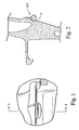
- the airfoil Hi-C point In a turbine bucket, at a given cross-section, the point at which the gas flow reverses its direction on the convex side of the airfoil is known as the airfoil Hi-C point. Particular interest is generally of the Hi-C point at the root cross-section, known as the root section Hi-C point, since the stress at this location is generally higher than its surrounding locations.
- the Hi-C may be located in such a way that when a bar-type damper pin slot is machined, there will be inevitable undercut 2 at the Hi-C location immediately below the platform (see the dashed line in FIG. 2 ).
- the Hi-C location is generally a highly stressed location, and an undercut 2 will further increase the stress at this location through Kt effect and the reduction of wall thickness.
- the Kt could be as high as 5.0.
- GB 1 585 186 discloses an arrangement for damping the coverplates of a turbine assembly.
- GB 2 226 368 discusses vibration damping in rotor blades.
- a turbine bucket and damper pin assembly including a damper pin is provided in accordance with appended claim 1.
- the damper pin includes slot insertion ends shaped to fit into the bucket damper slot; and at least a first scallop section formed or machined between the slot insertion ends and shaped to receive a bucket shank pocket radial contour.
- a second scallop section may also be formed or machined diametrically opposed and anti-symmetrical to the first scallop section between the slot insertion ends.
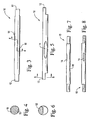
- the damper pin 10 includes slot insertion ends 12 and at least a first scallop section 14 formed between the slot insertion ends 12.
- a second scallop section 16 is formed diametrically opposed and anti-symmetrical to the first scallop section 14 between the slot insertion ends 12.
- the damper pin 10 can be inserted in a bucket damper slot in any orientation. See also, for example, FIG. 10 .
- the scallop sections 14, 16 are preferably horseshoe shaped or U-shaped at both ends transitioned into a substantially flat plane at the center.
- FIGS. 4 and 9 show the details of the cross section of the damper pin 10 through the scallop sections 14, 16.
- the trough faces 18 of the respective scallop sections 14, 16 are machined to be substantially parallel to the radial contour of the shank pocket at the Hi-C location, within manufacturing and assembly tolerances.
- the angle of the trough face of the scallop is about 12 degrees relative to the plane X shown in FIG. 9 .
- this value is only for illustration, and the invention is not meant to be limited to the noted example.
- FIGS. 10 and 11 illustrate the damper pin 10 installed in a bucket damper slot.
- a radial clearance c of the damper 10 within the bucket shank should be such that it will not create hot binding considering manufacturing and assembly tolerances and hot growths.
- the bucket damper slot is created when two adjacent buckets are assembled into the wheel.
- the insertion ends 12 of the damper pin 10 are supported in the bucket damper slot.
- the shape of the damper ends 12 and the slot are designed such that both sealing and frictional damping are ensured during operation.
- scalloped bucket damper pin of the present invention With the scalloped bucket damper pin of the present invention, undercut at airfoil root Hi-C of a turbine bucket can be avoided. Consequently, Kt stresses due to a Hi-C undercut at the critical stress location can be avoided. Additionally, by incorporating a second scallop section, damper placement at bucket assembly in the wheel can be facilitated.
Description
- The present invention relates to turbine bucket damper pins and, more particularly, eliminating or reducing bucket Hi-C undercut by incorporating a scallop section in a bucket damper pin.
- In a turbine bucket, at a given cross-section, the point at which the gas flow reverses its direction on the convex side of the airfoil is known as the airfoil Hi-C point. Particular interest is generally of the Hi-C point at the root cross-section, known as the root section Hi-C point, since the stress at this location is generally higher than its surrounding locations. With reference to
FIG. 1 , for buckets with a narrow bucket-to-bucket space due to real estate constraints, the Hi-C may be located in such a way that when a bar-type damper pin slot is machined, there will be inevitable undercut 2 at the Hi-C location immediately below the platform (see the dashed line inFIG. 2 ). The Hi-C location is generally a highly stressed location, and anundercut 2 will further increase the stress at this location through Kt effect and the reduction of wall thickness. For example, analysis has indicated that, for a particular bucket/damper geometry, the Kt could be as high as 5.0. -
GB 1 585 186 -
GB 2 226 368 - It would be desirable to construct the turbine bucket damper pin to avoid the undercut while providing an easily-installed assembly geometry.
- In an exemplary embodiment of the invention, a turbine bucket and damper pin assembly including a damper pin is provided in accordance with appended claim 1. The damper pin includes slot insertion ends shaped to fit into the bucket damper slot; and at least a first scallop section formed or machined between the slot insertion ends and shaped to receive a bucket shank pocket radial contour. A second scallop section may also be formed or machined diametrically opposed and anti-symmetrical to the first scallop section between the slot insertion ends.
- In another exemplary embodiment of the invention, a method of constructing the turbine bucket and damper pin assembly according to claim 1 is also provided.
- Embodiments of the invention will now be described, by way of example, with reference to the accompanying drawings, in which:
-
FIGURE 1 is a front view of a turbine bucket showing a Hi-C undercut; -
FIGURE 2 is a section view along lines 2-2 inFigure 1 ; -
FIGURE 3 is a plan view of a scalloped damper pin of the present invention; -
FIGURE 4 is a section view along the lines 4-4 inFigure 3 ; -
FIGURE 5 is a side view of the damper pin ofFigure 3 ; -
FIGURE 6 is an end view alongarrow 6 inFigure 5 ; -
FIGURES 7 and 8 are shaded plan and side views of the scalloped damper pin; -
FIGURE 9 is an enlarged view of theFigure 4 section along lines 4-4 inFigure 3 ; -
FIGURE 10 illustrates the damper pin installed in the bucket damper slot; and -
FIGURE 11 is a cross section through Hi-C when the damper is at its operating condition. - With reference to
FIGS. 3-8 , thedamper pin 10 includesslot insertion ends 12 and at least afirst scallop section 14 formed between theslot insertion ends 12. Preferably, asecond scallop section 16 is formed diametrically opposed and anti-symmetrical to thefirst scallop section 14 between the slot insertion ends 12. As seen, for example, inFIGS. 3 and 7 , by providing first 14 and second 16 scallop sections in an anti-symmetrical configuration, thedamper pin 10 can be inserted in a bucket damper slot in any orientation. See also, for example,FIG. 10 . - To facilitate machining of the
scallop sections scallop sections FIGS. 4 and9 show the details of the cross section of thedamper pin 10 through thescallop sections respective scallop sections FIG. 9 . Of course, this value is only for illustration, and the invention is not meant to be limited to the noted example. -
FIGS. 10 and 11 illustrate thedamper pin 10 installed in a bucket damper slot. At the assembled condition, a radial clearance c of thedamper 10 within the bucket shank should be such that it will not create hot binding considering manufacturing and assembly tolerances and hot growths. The bucket damper slot is created when two adjacent buckets are assembled into the wheel. The insertion ends 12 of thedamper pin 10 are supported in the bucket damper slot. Preferably, the shape of thedamper ends 12 and the slot are designed such that both sealing and frictional damping are ensured during operation. - With the scalloped bucket damper pin of the present invention, undercut at airfoil root Hi-C of a turbine bucket can be avoided. Consequently, Kt stresses due to a Hi-C undercut at the critical stress location can be avoided. Additionally, by incorporating a second scallop section, damper placement at bucket assembly in the wheel can be facilitated.
Claims (9)
- A turbine bucket and damper pin assembly, comprising two turbine buckets defining a bucket damper slot therebetween, the damper pin further comprising slot insertion ends (12) shaped to fit into the bucket damper slot; characterized in that
a first scallop section (14) is formed between the slot insertion ends and shaped to receive a bucket shank pocket radial contour. - The assembly according to claim 1, further comprising a second scallop section (16) formed diametrically opposed and anti-symmetrical to the first scallop section (14) between the slot insertion ends (12), the second scallop section being shaped to receive the bucket shank pocket radial contour.
- The assembly according to claim 2, wherein the first and second scallop sections (14, 16) are substantially U-shaped.
- The assembly according to claim 3, wherein a center of the first scallop section (14) and a center of the second scallop section (16) are substantially flat planes.
- The assembly according to claim 4, wherein a trough face (18) of the first scallop section (14) and a trough face (18) of the second scallop section (16) are substantially parallel to the bucket shank pocket radial contour within manufacturing and assembly tolerances.
- The assembly according to claim 1, wherein the first scallop section (14) is substantially U-shaped.
- A method of constructing a turbine bucket and damper assembly according to claim 1, the method comprising:(a) providing two turbine buckets defining a bucket damper slot therebetween;(b) forming slot insertion ends (12) shaped to fit into the bucket damper slot; and characterized by:(c) machining a first scallop section (14) between the slot insertion ends, the first scallop section being shaped to receive a bucket shank pocket radial contour.
- The method according to claim 7, further comprising (d) machining a second scallop section (16) diametrically opposed and anti-symmetrical to the first scallop section (14) between the slot insertion ends (12), the second scallop section (16) being shaped to receive the bucket shank pocket radial contour.
- The method according to claim 7, wherein step (c) is practiced by machining the first scallop section (14) to be substantially U-shaped.
Applications Claiming Priority (2)
| Application Number | Priority Date | Filing Date | Title |
|---|---|---|---|
| US373757 | 2003-02-27 | ||
| US10/373,757 US6776583B1 (en) | 2003-02-27 | 2003-02-27 | Turbine bucket damper pin |
Publications (3)
| Publication Number | Publication Date |
|---|---|
| EP1452692A2 EP1452692A2 (en) | 2004-09-01 |
| EP1452692A3 EP1452692A3 (en) | 2007-03-14 |
| EP1452692B1 true EP1452692B1 (en) | 2012-07-25 |
Family
ID=32771431
Family Applications (1)
| Application Number | Title | Priority Date | Filing Date |
|---|---|---|---|
| EP04251074A Expired - Lifetime EP1452692B1 (en) | 2003-02-27 | 2004-02-26 | Turbine bucket damper pin |
Country Status (4)
| Country | Link |
|---|---|
| US (1) | US6776583B1 (en) |
| EP (1) | EP1452692B1 (en) |
| JP (1) | JP4574189B2 (en) |
| CN (1) | CN100366866C (en) |
Families Citing this family (30)
| Publication number | Priority date | Publication date | Assignee | Title |
|---|---|---|---|---|
| US6851932B2 (en) * | 2003-05-13 | 2005-02-08 | General Electric Company | Vibration damper assembly for the buckets of a turbine |
| US7090466B2 (en) * | 2004-09-14 | 2006-08-15 | General Electric Company | Methods and apparatus for assembling gas turbine engine rotor assemblies |
| US7163376B2 (en) * | 2004-11-24 | 2007-01-16 | General Electric Company | Controlled leakage pin and vibration damper for active cooling and purge of bucket slash faces |
| US7367123B2 (en) * | 2005-05-12 | 2008-05-06 | General Electric Company | Coated bucket damper pin and related method |
| US7731482B2 (en) * | 2006-06-13 | 2010-06-08 | General Electric Company | Bucket vibration damper system |
| US7534090B2 (en) * | 2006-06-13 | 2009-05-19 | General Electric Company | Enhanced bucket vibration system |
| FR2923557B1 (en) * | 2007-11-12 | 2010-01-22 | Snecma | BLOWER DRAWER ASSEMBLY AND ITS SHOCK ABSORBER, BLOWER DAMPER AND METHOD FOR CALIBRATING THE SHOCK ABSORBER |
| US8226365B2 (en) * | 2009-04-22 | 2012-07-24 | General Electric Company | Systems, methods, and apparatus for thermally isolating a turbine rotor wheel |
| US8371816B2 (en) * | 2009-07-31 | 2013-02-12 | General Electric Company | Rotor blades for turbine engines |
| US8540486B2 (en) * | 2010-03-22 | 2013-09-24 | General Electric Company | Apparatus for cooling a bucket assembly |
| US8790086B2 (en) * | 2010-11-11 | 2014-07-29 | General Electric Company | Turbine blade assembly for retaining sealing and dampening elements |
| US9022727B2 (en) * | 2010-11-15 | 2015-05-05 | Mtu Aero Engines Gmbh | Rotor for a turbo machine |
| US8876478B2 (en) | 2010-11-17 | 2014-11-04 | General Electric Company | Turbine blade combined damper and sealing pin and related method |
| US8684695B2 (en) | 2011-01-04 | 2014-04-01 | General Electric Company | Damper coverplate and sealing arrangement for turbine bucket shank |
| US8876479B2 (en) | 2011-03-15 | 2014-11-04 | United Technologies Corporation | Damper pin |
| US8951014B2 (en) | 2011-03-15 | 2015-02-10 | United Technologies Corporation | Turbine blade with mate face cooling air flow |
| US8905715B2 (en) * | 2011-03-17 | 2014-12-09 | General Electric Company | Damper and seal pin arrangement for a turbine blade |
| US9309782B2 (en) | 2012-09-14 | 2016-04-12 | General Electric Company | Flat bottom damper pin for turbine blades |
| US9856737B2 (en) * | 2014-03-27 | 2018-01-02 | United Technologies Corporation | Blades and blade dampers for gas turbine engines |
| US10030530B2 (en) * | 2014-07-31 | 2018-07-24 | United Technologies Corporation | Reversible blade rotor seal |
| US9879548B2 (en) * | 2015-05-14 | 2018-01-30 | General Electric Company | Turbine blade damper system having pin with slots |
| US10584597B2 (en) * | 2015-09-03 | 2020-03-10 | General Electric Company | Variable cross-section damper pin for a turbine blade |
| US10385701B2 (en) | 2015-09-03 | 2019-08-20 | General Electric Company | Damper pin for a turbine blade |
| US10443408B2 (en) | 2015-09-03 | 2019-10-15 | General Electric Company | Damper pin for a turbine blade |
| US10472975B2 (en) | 2015-09-03 | 2019-11-12 | General Electric Company | Damper pin having elongated bodies for damping adjacent turbine blades |
| CN105781623B (en) * | 2016-03-04 | 2017-10-20 | 西安交通大学 | It is a kind of to reduce the lacing wire structure of flow-disturbing loss |
| US10519785B2 (en) | 2017-02-14 | 2019-12-31 | General Electric Company | Turbine blades having damper pin slot features and methods of fabricating the same |
| EP3438410B1 (en) | 2017-08-01 | 2021-09-29 | General Electric Company | Sealing system for a rotary machine |
| DE102018221533A1 (en) * | 2018-12-12 | 2020-06-18 | MTU Aero Engines AG | Turbomachinery blade arrangement |
| FR3096734B1 (en) * | 2019-05-29 | 2021-12-31 | Safran Aircraft Engines | Turbomachine kit |
Family Cites Families (23)
| Publication number | Priority date | Publication date | Assignee | Title |
|---|---|---|---|---|
| US3266770A (en) * | 1961-12-22 | 1966-08-16 | Gen Electric | Turbomachine rotor assembly |
| US4088421A (en) * | 1976-09-30 | 1978-05-09 | General Electric Company | Coverplate damping arrangement |
| GB2043796B (en) * | 1979-03-10 | 1983-04-20 | Rolls Royce | Bladed rotor for gas turbine engine |
| US4389161A (en) * | 1980-12-19 | 1983-06-21 | United Technologies Corporation | Locking of rotor blades on a rotor disk |
| US4936749A (en) * | 1988-12-21 | 1990-06-26 | General Electric Company | Blade-to-blade vibration damper |
| US5156528A (en) * | 1991-04-19 | 1992-10-20 | General Electric Company | Vibration damping of gas turbine engine buckets |
| US5478207A (en) * | 1994-09-19 | 1995-12-26 | General Electric Company | Stable blade vibration damper for gas turbine engine |
| US5685693A (en) | 1995-03-31 | 1997-11-11 | General Electric Co. | Removable inner turbine shell with bucket tip clearance control |
| US5823741A (en) | 1996-09-25 | 1998-10-20 | General Electric Co. | Cooling joint connection for abutting segments in a gas turbine engine |
| US5749705A (en) * | 1996-10-11 | 1998-05-12 | General Electric Company | Retention system for bar-type damper of rotor blade |
| US5803710A (en) * | 1996-12-24 | 1998-09-08 | United Technologies Corporation | Turbine engine rotor blade platform sealing and vibration damping device |
| GB9724731D0 (en) * | 1997-11-25 | 1998-01-21 | Rolls Royce Plc | Friction damper |
| JP2000008804A (en) * | 1998-06-25 | 2000-01-11 | Ishikawajima Harima Heavy Ind Co Ltd | Turbine rotor blade vibration control device of gas turbine |
| US6171058B1 (en) * | 1999-04-01 | 2001-01-09 | General Electric Company | Self retaining blade damper |
| DE60028446T2 (en) | 1999-04-23 | 2006-12-21 | General Electric Co. | Heating and cooling circuit for the inner casing of a turbine |
| US6390769B1 (en) | 2000-05-08 | 2002-05-21 | General Electric Company | Closed circuit steam cooled turbine shroud and method for steam cooling turbine shroud |
| US6413040B1 (en) | 2000-06-13 | 2002-07-02 | General Electric Company | Support pedestals for interconnecting a cover and nozzle band wall in a gas turbine nozzle segment |
| US6354803B1 (en) * | 2000-06-30 | 2002-03-12 | General Electric Company | Blade damper and method for making same |
| US6461110B1 (en) | 2001-07-11 | 2002-10-08 | General Electric Company | First-stage high pressure turbine bucket airfoil |
| US6478540B2 (en) | 2000-12-19 | 2002-11-12 | General Electric Company | Bucket platform cooling scheme and related method |
| US6481972B2 (en) | 2000-12-22 | 2002-11-19 | General Electric Company | Turbine bucket natural frequency tuning rib |
| US6450770B1 (en) | 2001-06-28 | 2002-09-17 | General Electric Company | Second-stage turbine bucket airfoil |
| US6506016B1 (en) | 2001-11-15 | 2003-01-14 | General Electric Company | Angel wing seals for blades of a gas turbine and methods for determining angel wing seal profiles |
-
2003
- 2003-02-27 US US10/373,757 patent/US6776583B1/en not_active Expired - Fee Related
-
2004
- 2004-02-26 JP JP2004050706A patent/JP4574189B2/en not_active Expired - Fee Related
- 2004-02-26 EP EP04251074A patent/EP1452692B1/en not_active Expired - Lifetime
- 2004-02-27 CN CNB2004100082402A patent/CN100366866C/en not_active Expired - Fee Related
Also Published As
| Publication number | Publication date |
|---|---|
| US6776583B1 (en) | 2004-08-17 |
| CN100366866C (en) | 2008-02-06 |
| CN1525047A (en) | 2004-09-01 |
| JP2004257391A (en) | 2004-09-16 |
| JP4574189B2 (en) | 2010-11-04 |
| EP1452692A2 (en) | 2004-09-01 |
| EP1452692A3 (en) | 2007-03-14 |
Similar Documents
| Publication | Publication Date | Title |
|---|---|---|
| EP1452692B1 (en) | Turbine bucket damper pin | |
| EP1882083B1 (en) | Locking arrangement for radial entry turbine blades | |
| US5295789A (en) | Turbomachine flow-straightener blade | |
| EP2758634B1 (en) | Impingement cooling of turbine blades or vanes | |
| US5797725A (en) | Gas turbine engine vane and method of manufacture | |
| US8192166B2 (en) | Tip shrouded turbine blade with sealing rail having non-uniform thickness | |
| EP1561904B1 (en) | Turbine blade with cutting edges on tip shroud | |
| EP1813771B1 (en) | Bladed rotor assembly | |
| EP1959098B1 (en) | Turbine rotor blade and turbine rotor | |
| US7753651B2 (en) | Balancing flyweight, rotor disk equipped therewith, rotor and aircraft engine comprising them | |
| CA2640028A1 (en) | Rotor blade, method for producing a rotor blade, and also compressor with such a rotor blade | |
| EP2184442A1 (en) | Airfoil fillet | |
| EP1698760B1 (en) | Torque-tuned, integrally-covered bucket and related method | |
| JP2012052523A (en) | Turbine blade assembly | |
| US20160024939A1 (en) | Rotor blade assembly, turbomachine comprising a rotor blade assembly and method of assembling a rotor blade assembly | |
| EP0799974B1 (en) | Seal for turbomachine blade | |
| JP2008002439A (en) | Bucket and assembly method | |
| EP2863017A1 (en) | Turbine with bucket fixing means | |
| US7121806B2 (en) | Welding method and an assembly formed thereby | |
| US8057170B2 (en) | Intermediate casing for a gas turbine engine | |
| EP2863016A1 (en) | Turbine with bucket fixing means | |
| CN104271893A (en) | Retaining clip, turbine frame, and method of limiting radial movement | |
| EP3058180B1 (en) | Fan rotor with integrated platform attachment | |
| RU2815341C1 (en) | Steam turbine working blade | |
| JPH03179105A (en) | Integral shrouded blade |
Legal Events
| Date | Code | Title | Description |
|---|---|---|---|
| PUAI | Public reference made under article 153(3) epc to a published international application that has entered the european phase |
Free format text: ORIGINAL CODE: 0009012 |
|
| AK | Designated contracting states |
Kind code of ref document: A2 Designated state(s): AT BE BG CH CY CZ DE DK EE ES FI FR GB GR HU IE IT LI LU MC NL PT RO SE SI SK TR |
|
| AX | Request for extension of the european patent |
Extension state: AL HR LT LV MK |
|
| PUAL | Search report despatched |
Free format text: ORIGINAL CODE: 0009013 |
|
| AK | Designated contracting states |
Kind code of ref document: A3 Designated state(s): AT BE BG CH CY CZ DE DK EE ES FI FR GB GR HU IE IT LI LU MC NL PT RO SE SI SK TR |
|
| AX | Request for extension of the european patent |
Extension state: AL LT LV MK |
|
| RIC1 | Information provided on ipc code assigned before grant |
Ipc: F01D 11/00 20060101ALI20070206BHEP Ipc: F01D 5/26 20060101ALI20070206BHEP Ipc: F01D 5/22 20060101AFI20040517BHEP |
|
| 17P | Request for examination filed |
Effective date: 20070914 |
|
| AKX | Designation fees paid |
Designated state(s): CH DE FR GB IT LI |
|
| 17Q | First examination report despatched |
Effective date: 20071026 |
|
| GRAP | Despatch of communication of intention to grant a patent |
Free format text: ORIGINAL CODE: EPIDOSNIGR1 |
|
| GRAS | Grant fee paid |
Free format text: ORIGINAL CODE: EPIDOSNIGR3 |
|
| GRAA | (expected) grant |
Free format text: ORIGINAL CODE: 0009210 |
|
| AK | Designated contracting states |
Kind code of ref document: B1 Designated state(s): CH DE FR GB IT LI |
|
| REG | Reference to a national code |
Ref country code: GB Ref legal event code: FG4D |
|
| REG | Reference to a national code |
Ref country code: CH Ref legal event code: NV Representative=s name: SERVOPATENT GMBH Ref country code: CH Ref legal event code: EP |
|
| REG | Reference to a national code |
Ref country code: DE Ref legal event code: R096 Ref document number: 602004038633 Country of ref document: DE Effective date: 20120920 |
|
| PGFP | Annual fee paid to national office [announced via postgrant information from national office to epo] |
Ref country code: FR Payment date: 20130311 Year of fee payment: 10 Ref country code: DE Payment date: 20130227 Year of fee payment: 10 Ref country code: GB Payment date: 20130227 Year of fee payment: 10 Ref country code: CH Payment date: 20130225 Year of fee payment: 10 |
|
| PLBE | No opposition filed within time limit |
Free format text: ORIGINAL CODE: 0009261 |
|
| STAA | Information on the status of an ep patent application or granted ep patent |
Free format text: STATUS: NO OPPOSITION FILED WITHIN TIME LIMIT |
|
| 26N | No opposition filed |
Effective date: 20130426 |
|
| REG | Reference to a national code |
Ref country code: DE Ref legal event code: R097 Ref document number: 602004038633 Country of ref document: DE Effective date: 20130426 |
|
| REG | Reference to a national code |
Ref country code: DE Ref legal event code: R119 Ref document number: 602004038633 Country of ref document: DE |
|
| REG | Reference to a national code |
Ref country code: CH Ref legal event code: PL |
|
| GBPC | Gb: european patent ceased through non-payment of renewal fee |
Effective date: 20140226 |
|
| PG25 | Lapsed in a contracting state [announced via postgrant information from national office to epo] |
Ref country code: CH Free format text: LAPSE BECAUSE OF NON-PAYMENT OF DUE FEES Effective date: 20140228 Ref country code: LI Free format text: LAPSE BECAUSE OF NON-PAYMENT OF DUE FEES Effective date: 20140228 |
|
| REG | Reference to a national code |
Ref country code: FR Ref legal event code: ST Effective date: 20141031 |
|
| REG | Reference to a national code |
Ref country code: DE Ref legal event code: R119 Ref document number: 602004038633 Country of ref document: DE Effective date: 20140902 |
|
| PG25 | Lapsed in a contracting state [announced via postgrant information from national office to epo] |
Ref country code: FR Free format text: LAPSE BECAUSE OF NON-PAYMENT OF DUE FEES Effective date: 20140228 Ref country code: DE Free format text: LAPSE BECAUSE OF NON-PAYMENT OF DUE FEES Effective date: 20140902 Ref country code: GB Free format text: LAPSE BECAUSE OF NON-PAYMENT OF DUE FEES Effective date: 20140226 |
|
| PG25 | Lapsed in a contracting state [announced via postgrant information from national office to epo] |
Ref country code: IT Free format text: LAPSE BECAUSE OF NON-PAYMENT OF DUE FEES Effective date: 20140226 |