EP1452407A1 - Air bag device for knee protection - Google Patents
Air bag device for knee protection Download PDFInfo
- Publication number
- EP1452407A1 EP1452407A1 EP02781867A EP02781867A EP1452407A1 EP 1452407 A1 EP1452407 A1 EP 1452407A1 EP 02781867 A EP02781867 A EP 02781867A EP 02781867 A EP02781867 A EP 02781867A EP 1452407 A1 EP1452407 A1 EP 1452407A1
- Authority
- EP
- European Patent Office
- Prior art keywords
- airbag
- folded
- occupant
- side wall
- knees
- Prior art date
- Legal status (The legal status is an assumption and is not a legal conclusion. Google has not performed a legal analysis and makes no representation as to the accuracy of the status listed.)
- Granted
Links
Images


Classifications
-
- B—PERFORMING OPERATIONS; TRANSPORTING
- B60—VEHICLES IN GENERAL
- B60R—VEHICLES, VEHICLE FITTINGS, OR VEHICLE PARTS, NOT OTHERWISE PROVIDED FOR
- B60R21/00—Arrangements or fittings on vehicles for protecting or preventing injuries to occupants or pedestrians in case of accidents or other traffic risks
- B60R21/02—Occupant safety arrangements or fittings, e.g. crash pads
- B60R21/16—Inflatable occupant restraints or confinements designed to inflate upon impact or impending impact, e.g. air bags
- B60R21/20—Arrangements for storing inflatable members in their non-use or deflated condition; Arrangement or mounting of air bag modules or components
- B60R21/205—Arrangements for storing inflatable members in their non-use or deflated condition; Arrangement or mounting of air bag modules or components in dashboards
- B60R21/206—Arrangements for storing inflatable members in their non-use or deflated condition; Arrangement or mounting of air bag modules or components in dashboards in the lower part of dashboards, e.g. for protecting the knees
-
- B—PERFORMING OPERATIONS; TRANSPORTING
- B60—VEHICLES IN GENERAL
- B60R—VEHICLES, VEHICLE FITTINGS, OR VEHICLE PARTS, NOT OTHERWISE PROVIDED FOR
- B60R21/00—Arrangements or fittings on vehicles for protecting or preventing injuries to occupants or pedestrians in case of accidents or other traffic risks
- B60R21/02—Occupant safety arrangements or fittings, e.g. crash pads
- B60R21/16—Inflatable occupant restraints or confinements designed to inflate upon impact or impending impact, e.g. air bags
- B60R21/23—Inflatable members
- B60R21/237—Inflatable members characterised by the way they are folded
-
- B—PERFORMING OPERATIONS; TRANSPORTING
- B60—VEHICLES IN GENERAL
- B60R—VEHICLES, VEHICLE FITTINGS, OR VEHICLE PARTS, NOT OTHERWISE PROVIDED FOR
- B60R21/00—Arrangements or fittings on vehicles for protecting or preventing injuries to occupants or pedestrians in case of accidents or other traffic risks
- B60R21/02—Occupant safety arrangements or fittings, e.g. crash pads
- B60R21/16—Inflatable occupant restraints or confinements designed to inflate upon impact or impending impact, e.g. air bags
- B60R21/23—Inflatable members
- B60R21/231—Inflatable members characterised by their shape, construction or spatial configuration
- B60R21/2334—Expansion control features
- B60R21/2338—Tethers
-
- B—PERFORMING OPERATIONS; TRANSPORTING
- B60—VEHICLES IN GENERAL
- B60R—VEHICLES, VEHICLE FITTINGS, OR VEHICLE PARTS, NOT OTHERWISE PROVIDED FOR
- B60R21/00—Arrangements or fittings on vehicles for protecting or preventing injuries to occupants or pedestrians in case of accidents or other traffic risks
- B60R2021/003—Arrangements or fittings on vehicles for protecting or preventing injuries to occupants or pedestrians in case of accidents or other traffic risks characterised by occupant or pedestian
- B60R2021/0039—Body parts of the occupant or pedestrian affected by the accident
- B60R2021/0051—Knees
-
- B—PERFORMING OPERATIONS; TRANSPORTING
- B60—VEHICLES IN GENERAL
- B60R—VEHICLES, VEHICLE FITTINGS, OR VEHICLE PARTS, NOT OTHERWISE PROVIDED FOR
- B60R21/00—Arrangements or fittings on vehicles for protecting or preventing injuries to occupants or pedestrians in case of accidents or other traffic risks
- B60R21/02—Occupant safety arrangements or fittings, e.g. crash pads
- B60R21/16—Inflatable occupant restraints or confinements designed to inflate upon impact or impending impact, e.g. air bags
- B60R21/23—Inflatable members
- B60R21/231—Inflatable members characterised by their shape, construction or spatial configuration
- B60R2021/23169—Inflatable members characterised by their shape, construction or spatial configuration specially adapted for knee protection
-
- B—PERFORMING OPERATIONS; TRANSPORTING
- B60—VEHICLES IN GENERAL
- B60R—VEHICLES, VEHICLE FITTINGS, OR VEHICLE PARTS, NOT OTHERWISE PROVIDED FOR
- B60R21/00—Arrangements or fittings on vehicles for protecting or preventing injuries to occupants or pedestrians in case of accidents or other traffic risks
- B60R21/02—Occupant safety arrangements or fittings, e.g. crash pads
- B60R21/16—Inflatable occupant restraints or confinements designed to inflate upon impact or impending impact, e.g. air bags
- B60R21/23—Inflatable members
- B60R21/231—Inflatable members characterised by their shape, construction or spatial configuration
- B60R21/2334—Expansion control features
- B60R21/2338—Tethers
- B60R2021/23382—Internal tether means
-
- B—PERFORMING OPERATIONS; TRANSPORTING
- B60—VEHICLES IN GENERAL
- B60R—VEHICLES, VEHICLE FITTINGS, OR VEHICLE PARTS, NOT OTHERWISE PROVIDED FOR
- B60R21/00—Arrangements or fittings on vehicles for protecting or preventing injuries to occupants or pedestrians in case of accidents or other traffic risks
- B60R21/02—Occupant safety arrangements or fittings, e.g. crash pads
- B60R21/16—Inflatable occupant restraints or confinements designed to inflate upon impact or impending impact, e.g. air bags
- B60R21/20—Arrangements for storing inflatable members in their non-use or deflated condition; Arrangement or mounting of air bag modules or components
- B60R21/205—Arrangements for storing inflatable members in their non-use or deflated condition; Arrangement or mounting of air bag modules or components in dashboards
-
- B—PERFORMING OPERATIONS; TRANSPORTING
- B60—VEHICLES IN GENERAL
- B60R—VEHICLES, VEHICLE FITTINGS, OR VEHICLE PARTS, NOT OTHERWISE PROVIDED FOR
- B60R21/00—Arrangements or fittings on vehicles for protecting or preventing injuries to occupants or pedestrians in case of accidents or other traffic risks
- B60R21/02—Occupant safety arrangements or fittings, e.g. crash pads
- B60R21/16—Inflatable occupant restraints or confinements designed to inflate upon impact or impending impact, e.g. air bags
- B60R21/20—Arrangements for storing inflatable members in their non-use or deflated condition; Arrangement or mounting of air bag modules or components
- B60R21/217—Inflation fluid source retainers, e.g. reaction canisters; Connection of bags, covers, diffusers or inflation fluid sources therewith or together
- B60R21/2171—Inflation fluid source retainers, e.g. reaction canisters; Connection of bags, covers, diffusers or inflation fluid sources therewith or together specially adapted for elongated cylindrical or bottle-like inflators with a symmetry axis perpendicular to the main direction of bag deployment, e.g. extruded reaction canisters
Definitions
- the present invention relates to a knee protection airbag device which protects knees of a vehicle occupant such as a driver or a passenger in front passenger's seat with an airbag expanding and inflating with inflation gas.
- Japanese Patent Laid-Open No.8-80797 and No. 10-315894 disclose devices for protecting the knees of a vehicle occupant such as a driver.
- the airbag device disclosed in the former is located below column cover, and includes an airbag to deploy for protecting the driver from shin to knee when actuated.
- the airbag device in the latter is located near the column cover below steering wheel, and includes an airbag to deploy for protecting the driver from lower side of the knee to the vicinity of toe when actuated.
- knee protection airbag devices have a room for improvement in inflating the airbags effectively along with the course of time from the start to completion of airbag deployment to protect the knees of the occupant.
- the first knee protection airbag device is arranged in front of knees of a seated vehicle occupant, with its airbag folded and housed therein. Upon inflow of inflation gas, the airbag protrudes rearward from a deployment opening of its housing to deploy upward, and is located in front of the knees of the occupant between a vehicle body and the occupant for protecting the knees of the occupant.
- the airbag includes an occupant's side wall to be disposed toward the occupant and a vehicular body side wall to be disposed toward the vehicular body, respectively upon deployment.
- a lower side of the airbag as flatly expanded with the vehicular body side. wall and the occupant's side wall overlaid on each other constitutes an upstream side of inflation gas.
- the airbag firstly is folded to bring its upper end close to its lower end from flat expanded state with the vehicular body side wall and the occupant's side wall overlaid on each other, and then folded to reduce its transverse width for housing.
- the airbag expands and inflates generally inversely to the folding process when inflation gas flows into the airbag. More specifically, the airbag protruded rearward from the deployment opening of the housing firstly unfolds from transversely narrowed state, thereby increasing the transverse width for covering the deployment opening and its periphery.
- the folding which has brought the upper end closer to the lower end is unfolded.
- the airbag has been expanded in transverse direction enough to cover the deployment opening and its periphery. Accordingly, the airbag deploys upward in the transversely expanded state.
- the airbag in the initial stage of deployment, protrudes rearward from the deployment opening of the housing, and expands and inflates widely in transverse direction so as to cover the deployment opening and its periphery, especially the left and right peripheries, for protecting the front side of the knees.
- the knee protection airbag device has just been actuated at this point. Since the vehicle is making a front collision, the knees of the occupant advance relative to the vehicle. However, since the airbag is deployed in transversely expanded state from the peripheral edge of the deployment opening, the airbag is able to protect the both knees of the occupant properly, even if brake operation or inertia force causes the knees to move right and left.
- the airbag After the airbag goes through the initial stage of deployment, the knees are bent and rise upward if the driver advances relative to the vehicle with his toes landed on the floor panel, whether or not the knees touch the airbag. By this time, the airbag has deployed upward in transversely expanded state over the periphery of deployment opening. Thus, the airbag completely deployed upward is able to protect the knees moving upward.
- the first knee protection airbag device is able to deploy the airbag effectively along with the course of time from the start to completion of airbag deployment, and thereby to protect the knees of the occupant properly.
- the first knee protection airbag device is able to configure inflated shape of the airbag properly along with the course of time from the start to completion of airbag deployment, the airbag does not have to be inflated largely from the initial stage of inflation so as to have a large protecting area. Accordingly, the airbag device is able to protect the knees of the occupant properly without employing an inflator with great output or an airbag with great capacity.
- the airbag is desirably roll-folded on the vehicular body side wall from the upper end when it is folded to bring the upper end close to the lower end.
- the roll-folded portion is unrolled when unfolded in deployment action. If the folded portion engages the occupant, unfolding of the folded portion and airbag deployment are rather accelerated than hindered by being contacted by the occupant. Consequently, the airbag is able to deploy smoothly without applying unnecessary pressure to the occupant.
- the left and right end sides of the folded portion of the airbag folded from the upper end toward the lower end are desirably folded to be located on the occupant's side wall and below transverse center of the folded portion.
- the left and right ends of the folded portion of the airbag folded to bring its upper end close to its lower end are housed on the occupant's side wall and below the transverse center of the folded portion.
- the left and right ends of the vertically folded portion unfold by turning upward to be back in the same horizontal line as a center of the vertically folded portion.
- the center of the vertically folded portion is prevented, by the left and right ends positioned on the occupant's side wall, from unfolding until the restoration of the left and right ends. Consequently, the center of the vertically folded portion is prevented from partially inflating upward.
- the unfolding of the vertically folded portion is performed generally uniformly in generally entire transverse area of the airbag after the left and right ends come in the same horizontal line with the central portion.
- the airbag is able to deploy upward further smoothly even if the space between the vehicular body side and the occupant is narrow.
- the left and right ends of the folded portion may be placed above the transverse center of the folded portion.
- the left and right ends of the folded portion may be placed either rearward or forward of the transverse center of the folded portion, either on the occupant's side wall or on the vehicular body side wall.
- This arrangement is preferably adopted for a compact folding of an airbag with great transverse width as flatly expanded with the occupant's side wall and the vehicular body side wall overlaid on each other.
- the left and right ends of the airbag folded to reduce its transverse width are located outward of knee centers of the left and right knees of the occupant, respectively, along the transverse direction.
- the airbag is housed in a condition capable of protecting the front side of the knees of the occupant from undeployed stage. Accordingly, the airbag is able to protect the knee centers of the knees of the occupant properly as soon as it protrudes rearward from the deployment opening of the housing in the initial stage of deployment.
- the left and right ends of the vertically folded portion have less folded and piled portion. Therefore, it is possible to reduce substantial depth of the housing space for the airbag.
- the airbag may include a tether joining the vehicular body side wall and the occupant's side wall for regulating thickness of the inflated airbag.
- This tether is desirably arranged along the transverse direction of the airbag so as to direct inflation gas from the upstream side within the airbag toward the left and right directions.
- inflation gas when flowing from the upstream side to the downstream side within the airbag, is directed outward in the transverse direction of the airbag. Therefore, the airbag is able to expand in the left and right direction further smoothly in the initial stage of deployment.
- an airbag as in the first knee protection airbag device is housed as only folded to bring the upper end close to the lower end from flat expanded condition in which the occupant's side wall and the vehicular body side wall are overlaid on each other.
- the airbag protrudes rearward from the deployment opening of the housing, and immediately deploys upward.
- the airbag in the initial stage of deployment is able to protect the knees properly in a wide area even if the knees are moved in the transverse direction.
- the airbag has already been through the initial stage of deployment, and deployed upward from a periphery of the deployment opening by that time. Therefore, the airbag is able to protect the rising knees with its part completely deployed upward.
- the second knee protection airbag device is able to deploy the airbag effectively along with the course of time from the start to completion of the airbag deployment, and thereby of protecting the knees of the occupant properly.
- the airbag In the second knee protection airbag device, moreover, the airbag is not folded to reduce its transverse width as in the first knee protection airbag device. Therefore, the airbag is able to complete deployment quickly.
- the folded airbag is desirably housed with its left and right ends located outward of the individual knee centers of the left and right knees of the occupant in the transverse direction.
- the airbag is housed in a condition capable of protecting the front side of the knees of the occupant from undeployed stage. Accordingly, the airbag is able to protect the knee centers of the knees of the occupant properly as soon as it protrudes rearward from the deployment opening of the housing in the initial stage of deployment.
- up-down, left-right, and front-rear in this specification correspond to the up-down, left-right, and front-rear of the vehicle as the knee protection airbag device is mounted on the vehicle.
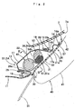
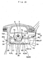
- the knee protection airbag device S1 of a first embodiment is arranged below steering column 3 in front of a driver MD as an occupant M for protecting the knees K of the driver MD.
- the steering column 3 is covered by a column cover 7.
- the steering column 3 includes a main shaft 4 connected to the steering wheel 1, and a column tube 5 covering the main shaft 4. Between the main shaft 4 and the column tube 5, there are arranged a not-shown tilt mechanism for adjusting the angle of ring face of the steering wheel 1, and a not-shown telescopic mechanism for shifting and stopping the steering wheel 1 in the axial direction of the shaft 4, and so on.
- the column cover 7 is formed of synthetic resin into a generally square cylindrical shape, and is so arranged along the axial direction of the steering column 3 as to cover the steering column 3. More specifically, the column cover 7 ascends backward to arrange its vehicular front side downward and its vehicular rear side upward.
- the lower surface 7a of a portion of the column cover 7 protruded from the instrument panel (as will be called “dashboard” hereinafater) 9 has a generally rectangular shape, and is curved to ascend backward in the longitudinal direction of the vehicle.
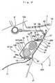
- the knee protection airbag device S1 includes a folded airbag 40, an inflator 34 for supplying the airbag 40 with inflation gas, an airbag cover 26 covering the folded airbag 40, and a housing case 13, and is arranged below the column cover 7 as a member of the vehicle body.
- the airbag 40, the inflator 34 and the airbag cover 26 are assembled with the housing case 13 to form an integral airbag module SA.
- the airbag device S1 is mounted on the vehicle by attaching the airbag module SA to the vehicle.
- the housing case 13 is made of a sheet metal. As shown in Figs. 1 to 4, the case 13 includes a plate-like portion 14 and a housing portion 17 for housing the folded airbag 40 and the inflator 34.
- the housing portion 17 has a bottomed box shape with an opening 17a directed rearward of the vehicle.
- the housing portion 17 has a generally rectangular parallelpiped box shape including a generally rectangular bottom wall 22 and a generally square cylindrical side wall portion 18.
- the side wall portion 18 enclosing the opening 17a is provided, in the walls 18a and 18b confronting each other in the transverse direction of the vehicle, with a large and small round mounting holes 20 and 21 for attaching the inflator 34.
- the mounting hole 20 is adapted to support the outer circumference of the later-described body 34a of the inflator 34 by the inner circumference when the cylindrical inflator body 34a is inserted thereinto.
- the inner diameter of the mounting hole 21 is so configured that the body 34a of the inflator 34 cannot go through, but the later-described male screw portion 34c of the inflator 34 may be inserted thereinto.
- the side of the male screw 34c of the inflator 34 is so inset into the mounting hole 20 from outward of the housing portion 17 as to protrude from the mounting hole 21. Then the male screw 34c is screwed into a nut 35.
- hooks 19 On the outer circumference of the side wall portion 18, there are fixed a plurality of hooks 19 having generally J-shaped section which have their leading ends bent toward the bottom wall 22 and away from the opening 17a.
- Four hooks 19 are disposed at the side of the later-described hinge line 30 in the airbag cover 26 (or at the lower side face of the case side wall portion 18), three hooks are disposed at the side of the leading end 31a of the later-described door 31 of the airbag cover 26 (or at the upper side face of the case side wall portion 18), and one each on the left and right side walls of the vehicle.
- the plate-like portion 14 extends from the peripheral edge of the opening 17a of the housing portion 17, and is so formed in a generally rectangular shape as to widely cover the front side of the left and right knees K (KL and KR) of the seated deriver MD.
- the plate-like portion 14 is provided at four corners of its periphery with four mounting pieces 15, respectively, for attachment to the vehicular body.
- the vicinity of the upper edge of the opening 17a in the plate-like portion 14 is recessed downward so that the lower surface 7a of the column cover 7 may protrude rearward, and is curved rearward along with the curve of the lower surface 17a.
- ribs 14a for stiffening the plate-like portion 14. These ribs 14a are adapted to support the later-described general portion 27 of the airbag cover 26 by their vehicle's rear side faces.
- mounting holes 14c are punched through. These mounting holes 14c are employed to attach the airbag cover 26 to the housing case 13 by means of thermal-caulking. More specifically, later-described mounting legs 27a of the airbag cover 26 are inserted into the individual mounting holes 14c. Then the heads of the individual mounting legs 27a are melted to enlarge their diameter, and are resolidified so as not to come off from the mounting holes 14c. By cooperation of the mounting legs 27a and the hooks 19, the airbag cover 26 is attached to the housing case 13.
- the individual mounting pieces 15 of the housing case 13 there are formed joint holes (not shown) for the bolt 24 fastening (refer to Fig. 4) to the body 1.
- the individual mounting pieces 15 are fastened by the bolts 24 to predetermined brackets secured to dashboard reinforcement, center brace or front body pillar as members of the vehicle body. These brackets help absorb impact by being plastically deformed.
- the housing case 13 is integrally molded by pressing to have the plate-like portion 14 and the housing portion 17.
- the housing case 13 may be formed by welding a sheet metal.
- the airbag cover 26 is formed of thermo-plastic elastomer of polyolefin or the like, and has a larger contour than the housing case 13 so as to cover the vehicle's rear side of the housing case 13, as shown in Figs. 1 to 4.
- the airbag cover 26 is arranged toward the lower panel 9b of the dashboard 9 around the column cover 7 to cover the lower periphery of the column cover 7 protruded from the dashboard 9. Accordingly, the airbag cover 26 is recessed downward at its upper center as viewed from the vehicle's rear side to correspond to the rearward protrusion of the column cover 7. The upper edge of the airbag cover 26 is curved and raised rearward below the recess along with the curve of the column cover lower surface 7a.
- the dashboard 9 is composed of an upper panel 9a and the lower panel 9b.
- the airbag cover 26 includes a door 31 covering the opening 17a of the housing portion 17, and a general portion 27 covering the vehicle's rear side of the plate-like portion 14.
- the door 31 is formed in a generally rectangular plate shape slightly larger than the opening 17a.
- a weakened breakable portion 29 continuous from the general portion 27 for helping the door 31 open downward.
- the breakable portion 29 is formed by providing continuous or Intermittent grooves in the vehicle's front side face as to be easily broken when the door 31 is pushed by the airbag 40 inflating.
- the hinge line 30 is an integral hinge, and is thick enough not to be broken but thinner than the general portion 27 and the door 31.
- a deployment opening 32 is provided when the breakable portion 29 is broken to open the door 31 around the hinge line 30. Through the deployment opening 32, the airbag 40 upon deployment protrudes rearward of the vehicle from the housing portion 17.
- each of the mounting pieces 28 is formed in a generally rectangular plate shape, and is inserted through each of the through holes 14b in the plate-like portion 14 of the housing case 13.
- Each of the mounting pieces 28 is provided with a retaining hole 28a to be retained at the peripheral edge by the hook 19.
- the retaining hole 28a is opened in a rectangular shape.
- each of the mounting legs 27a has such a round rod shape as to pass through the mounting hole 14c. As shown in Fig. 3, the heads of the mounting legs 27a are crushed after thermal-caulking.
- the inflator 34 is of a cylinder type, and is constructed to discharge inflation gas G in response to an electric signal.
- the inflator 34 includes a cylindrical body 34a with a plurality of gas discharge ports 34b.
- the male screw portion 34c is protruded from one end of the body 34a.
- the inflator 34 is put in the housing portion 17 from the mounting hole 20, so that the male screw portion 34c is protruded from the mounting hole 21.
- the inflator 34 is housed in and held by the housing case 13.
- the inflator 34 is inserted through the later-described mounting holes 42a and 42b of the airbag 40.
- This inflator 34 is actuated in response to an electric signal from a not-shown control device.
- the control device also puts a not-shown airbag device mounted on the steering wheel 1 in action.
- the control device inputs an electric signal for actuation simultaneously to the inflator 34 and the airbag device for steering wheel.
- a connector 36 is connected to the end face of the body 34a protruded from the housing portion 17.
- a lead wire 37 led from an airbag actuating circuit is connected the connector 36.
- the airbag 40 is formed of a flexible woven fabric of polyester, polyamide or the like, and has a generally rectangular plate shape as expanded and inflated completely, as shown in Figs. 4 to 6.
- the airbag 40 includes a mounting portion 40b at the lower end side, and a body 40a arranged above the mounting portion 40b.
- the mounting portion 40b is provided with mounting holes 42a and 42b.
- the airbag 40 has a small transverse width at the mounting portion 40b, and a larger transverse width at the body 40a.
- the airbag 40 is formed of two woven fabrics, i.e., an occupant's side wall 41 at the side of the driver MD and a vehicular body side wall 42 at the side of the column cover 7, each of which having a generally rectangular shape.
- the airbag 40 is formed by sewing up the peripheral edges of the walls 41 and 42.
- the mounting hole 42a has its inner diameter generally equal to the outer diameter of the body 34a of the inflator 34 so that the body 34a may be inserted therethrough.
- the mounting hole 42b has such a smaller inner diameter than the outer diameter of the body 34a as to pass the male screw portion 34c through.
- the inflator body 34a is inserted into the mounting hole 42a, and the male screw portion 34c is inserted into the mounting hole 42b. Then the inner circumferences of the mounting holes 42a and 42b are supported by the body 34a and the male screw portion 34c of the inflator 34.
- the airbag 40 is attached to the housing case 13 utilizing the inflator 34 housed in the housing portion 17.
- the airbag 40 is provided with two band-shaped tethers 43 and 44 arranged up and down along the transverse direction.
- the tethers 43 and 44 function as a thickness regulating means to uniform the thickness of the deployed airbag 40 so that the airbag 40 may smoothly go in between the knees K of the driver MD and the column cover lower surface 7a.
- the tethers 43 and 44 are configured to connect the occupant's side wall 41 and the vehicular body side wall 42.
- the left and right ends 43a, 43b, 44a and 44b of the tethers 43 and 44 are apart from the left and right edges 49 and 50 of the airbag 40.
- the airbag body 40a upon deployment, protrudes rearward from a deployment opening 32 provided by the opening of the door 31, and covers from the vehicle's rear side face of the general portion 27 of the airbag cover 26 including the left and right periphery of the opening 32, up to at least the vicinity of the upper end 7b of the column cover lower surface 7a, and also covers the front side of the knees K (KL and KR) of the driver MD.
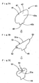
- Figs. 7 illustrate the folding process of the airbag 40.
- the airbag 40 is folded from flat expanded state in which the vehicular body side wall 42 and the occupant's side wall 41 are overlaid on each other to bring its upper end 47 closer to the lower end 48.
- the upper end 47 side is roll-folded on the vehicular body side wall 42.
- a vertically folded portion 51 is formed with a smaller vertical dimension than that of the airbag 40.
- left and right ends 52 and 53 of the roll-folded portion 51 are folded back so that the transverse width of the airbag 40 may be narrowed and fit the transverse width of the housing portion 17.
- the left and right ends 52 and 53 are folded upward (more specifically, upward on the vehicular body side wall 42, or obliquely up and forward, as shown in Fig. 2).
- the airbag 40 After folding, the airbag 40 is wrapped around by a not-shown breakable wrapping film for keeping the folded-up shape. Subsequently, the airbag 40 is housed in the housing portion 17 so that the mounting holes 20 and 42a, and the mounting holes 21 and 42b may match each other. At this time, the wrapping film is broken at portions of the mounting holes 42a and 42b.
- the male screw portion 34c is inserted into the airbag 40 housed in the housing portion 17 from the mounting holes 20 and 42a, and then protruded from the mounting holes 42b and 21. Then the nut 35 is fastened with the protruded male screw portion 34c, so that the end face of the body 34a with the male screw 34c is pressed onto the inner circumference of the housing portion 17 (or the wall 18b) with the peripheral edge of the mounting hole 42a of the airbag 40 interposed. Thus the inflator 34 and the airbag 40 are attached to the housing portion 17.
- the airbag cover 26 is attached to the housing case 13.
- the mounting pieces 28 are individually inserted into the corresponding through holes 14b from vehicle's rear side of the housing case 13, while the round-headed mounting legs 27a are inserted into the corresponding mounting holes 14c.
- each of the mounting pieces 28 engages the hook 19 and is elastically deformed to go away from the housing portion 17.
- each of the mounting pieces 28 restores and the hook 19 is inserted into the retaining hole 28a. Consequently, the hooks 19 retain the peripheral edges of the mounting holes 28a.
- each of the heads of the mounting legs 27a protruded from the respective mounting hole 14c is thermal-caulked and retained at the peripheral edge of the mounting hole 14c on the vehicle's front side face of the plate-like portion 14.
- the airbag cover 26 is attached to the housing case 13, and thus the airbag module SA is formed.
- the knee protection airbag device S1 is mounted on the vehicle.
- the lead wire 37 is connected to the airbag actuating circuit, and the upper panel 9a and the lower panel 9b of the dashboard 9, and the under cover 11 (refer to Figs. 1 and 2) are attached to the vehicle.
- the airbag device S1 After the airbag device S1 is mounted on the vehicle, if a predetermined electric signal is inputted to the inflator 34, inflation gas G is discharged from the gas discharge ports 34b to inflate the airbag 40. Then the airbag 40 breaks the not-shown wrapping film, pushes the door 31 of the airbag cover 26 and breaks the breakable portion 29, so that the door 31 opens downward on the hinge line 30. Accordingly, the airbag 40 protrudes rearward from the opening 17a of the housing portion 17 and through the deployment opening 32 of the airbag cover 26 provided by the opening of the door 31. The airbag 40 further expands and inflates upward along the column cover lower surface 7a, as shown in Figs. 8, 9A and 9B.
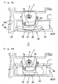
- the airbag 40 expands and inflates generally inversely to the folding process when inflation gas G flows into the airbag 40. More specifically, as shown in Fig. 9A, the airbag 40 protruded rearward from the deployment opening 32 firstly unfolds the left and right ends 52 and 53 from transversely narrowed state, thereby increasing its transverse width for covering the deployment opening 32 and its periphery.
- the airbag 40 protrudes rearward from the deployment opening 32 of the housing portion 17, and expands and inflates widely in transverse direction so as to cover the deployment opening 32 and its periphery, especially the left and right peripheries for protecting the knees K (KL and KR), in the initial stage of deployment, as shown in Figs. 8 and 9A.
- the knee protection airbag device S1 has just been actuated at this point.
- the knees K of the occupant MD advance relative to the vehicle (refer to Fig. 1).
- the airbag 40 is deployed in transversely expanded state from the peripheral edge of the deployment opening 32, the airbag 40 is able to protect the both knees K (KL and KR, refer to Fig. 4) of the occupant MD properly, even if brake operation or inertia force causes the knees K to move right and left.
- the knees K are bent and rise (refer to Fig. 8) if the driver MD advances relative to the vehicle with his toes landed on the floor panel, whether or not the knees K touch the airbag 40.
- the airbag 40 has deployed upward in transversely expanded state over the periphery of deployment opening 32, as shown in Fig. 9B.
- the airbag 40 completely deployed upward is able to protect the knees K moving upward.
- the knee protection airbag device S1 in the first embodiment is able to deploy the airbag 40 effectively along with the course of time from the start to completion of the deployment of airbag 40, and thereby to protect the knees K (KL and KR) of the occupant MD properly.
- the knee protection airbag device S1 in the foregoing embodiment is able to configure inflated shape of the airbag 40 properly along with the course of time from the start to completion of airbag deployment. More specifically, the airbag does not have to be inflated largely so as to have a large protecting area from the initial stage of inflation. Accordingly, the airbag device S1 is able to protect the knees KL and KR of the occupant MD properly without employing an inflator 34 with great output or an airbag 40 with great capacity.
- the airbag 40 is roll-folded on the vehicular body side wall 42 to bring the upper end 47 of the airbag 40 closer to the lower end 48 at the beginning.
- the roll-folded portion 51 is unrolled. If the folded portion 51 engages the occupant MD, unrolling of the portion 51 and airbag deployment are rather accelerated than hindered by being contacted by the occupant MD. Therefore, the airbag 40 is able to deploy smoothly without applying unnecessary pressure to the occupant MD.
- the inflation gas G flows toward the left and right directions by the lower tether 44 transversely arranged when flowing from the upstream side of inflation gas G, or the side of the mounting portion 40b toward the body 40a, as shown in Fig. 5.
- the gas G further flows into a part above the tether 44 through gas communication passages 45 formed between the inner surface of the left and right edges 49 and 50 of the airbag 40 and the left and right ends 44a and 44b of the tether 44.
- the inflation gas G is directed outward in the left and right direction. Consequently, the airbag body 40a is able to expand in the left and right direction further smoothly in the initial stage of deployment.
- the airbag 40 may be roll-folded on the occupant's side wall 41, or may be folded in a bellows fashion at the beginning of the folding while bringing the upper end 47 closer to the lower end 48.
- the airbag 40 may be cactus-folded by putting the upper end 47 side within the airbag 40 and bringing the same closer to the lower end 48.
- the tether 44 may be arranged in V-shape or U-shape as viewed from the vehicle's rear side, instead of being arranged along transverse direction.
- housing portion 17 for housing the airbag 40 has a great transverse width, only one of the left and right ends 52 and 53 of the folded portion 51 may be folded in the folding of the airbag 40.
- the following folding method may also be adopted.
- the airbag 40A is roll-folded on the vehicular body side wall 42 bringing the upper end 47 closer to the lower end 48 from flat expanded state.
- the left and right ends 52 and 53 of the folded portion 51 are folded in a bellows fashion.
- the left and right ends 52 and 53 of the folded portion 51 are individually roll-folded internally toward the transverse center 51a of the folded portion 51.
- Fig. 10D the left and right ends 52 and 53 of the folded portion 51 are individually roll-folded internally toward the transverse center 51a of the folded portion 51.
- the folded portion 51 may be folded by roll-folding the individual left and right ends 52 and 53 outwardly. In either case, the ends 52 and 53 are brought closer to each other to complete the folding.
- These folding methods are preferably adopted in compactly folding an airbag 40A with great transverse width as flat expanded with the vehicular body side wall 42 and the occupant's side wall 41 overlaid on each other.
- the left and right ends 52 and 53 of the folded portion 51 may be folded asymmetrically.
- the left end 52 side may be bellows-folded while the right end 53 side is roll-folded internally or outwardly. The inversion of this may be adopted, too.
- left and right ends 52 and 53 sides of the folded portion 51 may be folded and placed at positions other than the upper side relative to the central portion 51a of the folded portion 51.
- a knee protection airbag device S2 of the second embodiment shown in Fig. 11 for example, the left and right ends 52 and 53 sides of the roll-folded portion 51 in an airbag 40B are placed rearward of the central portion 51a of the folded portion 51.
- the airbag 40B is firstly roll-folded on the vehicular body side wall 42 bringing the upper end 47 of the flat expanded airbag 40B closer to the lower end 48, as shown in Figs. 12A and 12B.
- the left and right ends 52 and 53 of the folded portion 51 are folded back rearward to complete the folding work of the airbag 40B.
- the airbag 40B is housed in the case 13, as the airbag 40, thereby forming an airbag module SA for attachment to the vehicle.
- the left and right ends 52 and 53 may be folded forward or downward relative to the central portion 51a of the folded portion 51 when completing the folding work.
- an airbag 40C is housed in the housing portion 17 with its left and right ends 52 and 53 folded forward (more particularly, toward the front lower side) in the final stage of folding work.
- the airbag may be roll-folded once more in the final stage of folding work.
- an airbag 40D is roll-folded on the vehicular body side wall 42 bringing the upper end 47 of the flat expanded airbag 40D closer to the lower end 48.
- the left and right ends 52 and 53 of the folded potion 51 are folded back either forward, rearward or upward so as to fit the transverse width of the housing portion 17.
- the folded portion 55 is folded back on the vehicular body side wall 42, and thus the folding work of the airbag 40D is completed.
- the airbag 40D is housed in the case 13, as the airbag 40, thereby forming an airbag module SA for attachment to the vehicle.
- left and right ends 52 and 53 of the folded potion 51 of an airbag 40E may be folded downward relative to a central portion 51a of the folded portion 51 on the occupant's side wall 41.
- folding of the airbag 40E begins, from flat expanded state in which the vehicular body side wall 42 and the occupant's side wall 41 are overlaid on each other, with roll-folding to bring its upper end 47 closer to the lower end 48 on the vehicular body side wall 42.
- the left and right ends 52 and 53 of the roll-folded portion 51 are folded back to narrow the transverse width of the airbag 40E to fit the transverse width of the housing portion 17.
- the left and right ends 52 and 53 are so folded on the occupant's side wall 41 as to be located below the transverse center 51a of the folded portion 51.
- the airbag 40E is mounted on the vehicle in the same process as the first embodiment.
- the left and right ends 52 and 53 of the folded portion 51 unfold by turning upward and come back in the same horizontal line as the center 51a of the folded portion 51.
- the center 51a of the folded portion 51 is prevented, by the left and right ends 52 and 53 positioned on the occupant's side wall 41, from unfolding until the restoration of the left and right ends 52 and 53.
- the center 51a of the folded portion 51 is prevented from partially inflating upward until the left and right ends 52 and 53 are restored by unfolding.
- the unfolding of the folded portion 51 is performed as follows: Firstly, as in Fig.
- the left and right ends 52 and 53 turn upward and are placed in the same horizontal line as the center 51a while the center 51a is prevented from partially inflating upward. Then as shown in Fig. 17B, the unfolding of the folded portion 51 is performed generally uniformly in generally entire transverse area.
- the airbag 40E of the fourth embodiment deploys upward while partial thickening is prevented, the airbag 40E is able to deploy upward further smoothly even if a gap between the column cover lower surface 7a on the vehicular body side and the driver MD is narrow.
- the airbag 40A elongated in the transverse direction may be folded as follows : Firstly, as shown in Figs. 18A and 18B, the airbag 40A is roll-folded on the vehicular body side wall 42 bringing the upper end 47 closer to the lower end 48 from flat expanded state. Subsequently, as shown in Fig. 18C, the left and right ends 52 and 53 of the folded portion 51 are bellows-folded on the occupant's side wall, and are finally brought close to each other.
- Fig. 18A and 18B the airbag 40A is roll-folded on the vehicular body side wall 42 bringing the upper end 47 closer to the lower end 48 from flat expanded state.
- the left and right ends 52 and 53 of the folded portion 51 are bellows-folded on the occupant's side wall, and are finally brought close to each other.
- Fig. 18C the left and right ends 52 and 53 of the folded portion 51 are bellows-folded on the occupant's side wall, and are finally
- the left and right ends 52 and 53 of the folded portion 51 may be individually roll-folded internally toward the transverse center 51a.
- the left and right ends 52 and 53 of the folded portion 51 may be roll-folded outwardly and finally brought close to each other.
- These folding methods are preferably adopted in the airbag 40A with great transverse width as flatly expanded with the vehicular body side wall 42 and the occupant's side wall 41 overlaid on each other.
- the left and right ends 52 and 53 of the folded portion 51 may be folded asymmetrically.
- the left end 52 side may be roll-folded outwardly while the right end 53 side is roll-folded internally.
- the inversion may also be adopted, or alternatively, one side may be bellows-folded.
- left and right ends 52 and 53 of the folded portion 51 may also be folded and located toward obliquely lower rear side, for example, not only right below the center 51a of the folded portion 51.
- the left and right ends 52 and 53 of the roll-folded portion 51 of the airbag 40F may be folded and located below the center 51a of the folded portion 51, and below the body 34a of the inflator 34 on the occupant's side wall 41.
- This airbag 40F is firstly roll-folded on the vehicular body side wall 42 bringing the upper end 47 of the flat expanded airbag 40F close to the lower end 48, as shown in Figs. 20A and 20B. Subsequently, as shown in Fig.
- the left and right ends 52 and 53 of the roll-folded portion 51 are folded on the occupant's side wall 41 and below the inflator body 34a to complete the folding work. Thereafter, as the airbag 40, the airbag 40F is housed in the housing case 13 to form an airbag module SA, and is mounted on the vehicle.
- the airbag When the airbag is folded to reduce its transverse width, the airbag may be folded as an airbag 40G in a knee protection airbag device M6 of a sixth embodiment shown in Figs. 21 to 24.
- the housing case 13A In this airbag device M6, the housing case 13A is fixed to the dashboard reinforcement IF at left and right upper mounting pieces 15A.
- the door 31 of the airbag cover 26A is formed transversely long corresponding to an opening 17a of the widened housing portion 17A.
- the sixth embodiment differs from the first embodiment in these points, and in a folding method of the airbag 40G. However, other parts of the sixth embodiments are constructed similarly to the first embodiment.
- the airbag 40G is firstly roll-folded on the vehicular body side wall 42 bringing the upper end 47 of the flat expanded state close to the lower end 48. Subsequently, as shown in Fig. 24C, the left and right ends 52 and 53 of the folded portion 51 are folded back on the occupant's side wall 41 and below the inflator body 34a, to complete the folding work. At this time, the left and right ends 56 and 57 of the completely folded airbag 40G, as mounted on the vehicle, are located outward of the knee centers LC and RC (refer to Figs. 23 and 25) of the knees KL and KR of the driver MD along the transverse direction.
- the airbag 40G is housed in the housing case 13A as the airbag 40 to form an airbag module SA, and is mounted on the vehicle.
- the airbag 40G in housed state is wide enough to protect the front side of the knees KL and KR of the driver MD. As shown in Fig. 25, therefore, if the airbag 40G protrudes rearward from the deployment opening 32 of the housing portion 17A in the initial stage of deployment, the airbag 40G is able to protect the individual knee centers LC and RC of the knees KL and KR of the driver MD properly.
- the folded and piled portion of the left and right ends 52 and 53 sides in the folded portion 51 is less than other embodiments. Therefore, it is possible to reduce substantial depth of housing space for the airbag 40G.
- the left and right ends 52 and 53 of the folded portion 51 can be folded back upward, rearward, or forward of the center 51a of the folded portion 51. Alternatively, only one of the left and right ends 52 and 53 may be folded back. Further alternatively, in bringing the upper end 47 close to the lower end 48, the airbag 40G may be roll-folded on the occupant's side wall 41, bellows-folded, or cactus-folded.
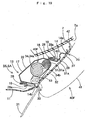
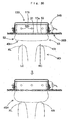
- a construction of a knee protection airbag device S7 of a seventh embodiment shown in Figs. 26 to 28 may be adopted.
- this airbag device M7 a housing portion 17B of ahousingcase 13B, together with an inflator 34B and a mounting portion 40b of an airbag 40H, has an even wider transverse width compared with the airbag device S6.
- the door 31 of the airbag cover 26B is formed transversely long corresponding to an opening 17a of the widened housing portion 17B.
- folding method of the airbag 40H differs from that of the sixth embodiment.
- the seventh embodiment is similarly constructed to the sixth embodiment.
- the airbag 40H is folded from flat expanded state in which the vehicular body side wall 42 and the occupant's side wall 41 are overlaid on each other, bringing the upper end 47 close to the lower end 48.
- the airbag 40H only thus folded is housed in the housing portion 17B of the housing case 13B to form an airbag module SA. Then the airbag module SA is mounted on the vehicle.
- the transverse width of the airbag 40H as completely deployed is so configured as to widely cover the front side of the knees KL and KR of the driver MD, as the aforementioned airbags.
- the folded airbag 40H is housed in the housing portion 17B so that the left and right ends 52 and 53 may be located outward of the knee centers LC and RC of the left and right knees KL and KR of the driver MD in the transverse direction.
- the airbag 40H protrudes rearward from the deployment opening 32 of the housing portion 17B, and immediately deploys upward.
- the airbag 40H in the initial stage of deployment is able to protect the knees KL and KR properly in a wide area even if the knees KL and KR are moved in the transverse direction.
- the airbag 40H has already been through the initial stage of deployment, and deployed upward from the periphery of the deployment opening 32 by that time, as indicated by double-dotted lines in Fig. 26. Therefore, the airbag 40H is able to protect the rising knees K with a part 40a thereof completely deployed upward.
- the knee protection airbag device S7 of the seventh embodiment is able to deploy the airbag 40H effectively along with the course of time from the start to completion of the airbag 40H deployment, and to protect the knees K of the driver MD properly.
- the airbag 40H is not folded to reduce its transverse width, not like the airbag 40 of the first embodiment. In the airbag device S7, accordingly, the airbag 40H is able to complete the deployment quickly.
- the left and right ends 52 and 53 of the folded portion 51 are not folded, and therefore, substantial depth of housing space for airbag 40H is possibly reduced in comparison with other embodiments.
- the airbag 40H is housed in the housing portion 17B with the left and right ends 52 and 53 located outward of the individual knee centers LC and RC of the left and right knees KL and KR of the driver MD in the transverse direction. Accordingly, the airbag 40H is able to protect the knee centers LC and RC of the left and right knees KL and KR of the driver MD properly as soon as it protrudes rearward from the deployment opening 17a of the housing portion 17B in the initial stage of deployment.
- the airbag 40H when bringing the upper end 47 close to the lower end 48, the airbag 40H may be roll-folded on the occupant's side wall 41, bellows-folded or cactus-folded.
- the foregoing embodiments have taken the airbag devices S1, S2, S3, S4, S5, S6 and S7 arranged in front of the driver MD for protecting the knees K of the driver MD as an example.
- the airbag device may be located in front of a front seat passenger MP seated in front passenger's seat for protecting the knees K (KL and KR) of the front seat passenger MP.
- an airbag 40A employed therein has a wider transverse width as shown in Fig. 10, than the airbag 40 of the airbag device S1, and folded as in Figs. 10A, 10B and 10C before housed.
- the plate-like portion 14 of the housing case 13 and the airbag cover 26 are formed flatly corresponding to a portion of the dashboard 9 in front of the front passenger's seat. Except these points, other parts of the airbag device S8 are constructed similarly to the airbag device S1.
Landscapes
- Engineering & Computer Science (AREA)
- Mechanical Engineering (AREA)
- Air Bags (AREA)
Abstract
Description
Claims (11)
- A knee protection airbag device arranged in front of knees of a seated vehicle occupant, the airbag device comprising an airbag folded and housed in undeployed condition, and upon inf low of inflation gas, the airbag protruding rearward from a deployment opening of the housing to deploy upward and be located in front of the knees of the occupant between a vehicle body and the occupant for protecting the knees of the occupant,
the airbag comprising an occupant's side wall to be disposed toward the occupant and a vehicular body side wall to be disposed toward the vehicular body, respectively upon deployment,
a lower side of the airbag as flatly expanded with the occupant's side wall and the vehicular body side wall overlaid on each other constitutes an upstream side of inflation gas,
in a folding process, the airbag firstly is folded to bring an upper end thereof close to a lower end thereof from flat expanded state in which the occupant's side wall and the vehicular body side wall are overlaid on each other, and then folded to reduce transverse width thereof, and is housed as thus folded. - A knee protection airbag device according to Claim 1, wherein the airbag is roll-folded on the vehicular body side wall from the upper end when the upper end of the airbag is brought close to the lower end.
- A knee protection airbag device according to Claim 1, wherein, when reducing the transverse width of the airbag, the left and right ends of the folded portion of the airbag folded to bring the upper end close to the lower end are folded back to be located on the occupant's side wall and below transverse center of the folded portion.
- A knee protection airbag device according to Claim 1, wherein, when reducing the transverse width of the airbag, the left and right ends of the folded portion of the airbag folded to bring the upper end close to the lower end are folded back to be located above the transverse center of the folded portion.
- A knee protection airbag device according to Claim 1, wherein, when reducing the transverse width of the airbag, the left and right ends of the folded portion of the airbag folded to bring the upper end close to the lower end are folded back to be located on the occupant's side wall and rearward of the transverse center of the folded portion.
- A knee protection airbag device according to Claim 1, wherein, when reducing the transverse width of the airbag, the left and right ends of the folded portion of the airbag folded to bring the upper end close to the lower end are folded back to be located on the vehicular body side wall and forward of the transverse center of the folded portion.
- A knee protection airbag device according to Claim 1, wherein, when reducing the transverse width of the airbag, the left and right ends of the folded portion of the airbag folded to bring the upper end close to the lower end are roll-folded toward the transverse center of the folded portion so as to be close to each other.
- A knee protection airbag device according to Claim 1, wherein the left and right ends of the airbag folded to reduce the transverse width thereof are located outward of knee centers of the left and right knees of the occupant, respectively, along the transverse direction.
- A knee protection airbag device according to Claim 1, wherein:the airbag further comprises a tether for joining the vehicular body side wall and the occupant's side wall to regulate thickness of the inflated airbag; andthe tether is arranged along the transverse direction so as to direct inflation gas flowing from the upstream side of the airbag toward the left and right directions of the airbag.
- A knee protection airbag device arranged in front of knees of a seated vehicle occupant, the airbag device comprising an airbag folded and housed in undeployed condition, and upon inf low of inflation gas, the airbag protruding rearward from a deployment opening of a housing to deploy upward and be located in front of the knees of the occupant between a vehicle body and the occupant for protecting the knees of the occupant,
the airbag comprising an occupant's side wall to be disposed toward the occupant and a vehicular body side wall to be disposed toward the vehicular body, respectively upon deployment,
a lower side of the airbag constitutes an upstream side of inflation gas as flatly expanded with the occupant's side wall and the vehicular body side wall overlaid on each other,
the airbag is folded to bring an upper end thereof close to a lower end thereof from flat expanded state in which the occupant's side wall and the vehicular body side wall are overlaid on each other, and is housed as thus folded. - A knee protection airbag device according to Claim 10, wherein the airbag folded and housed has left and right ends thereof located outward of knee centers of the left and right knees of the occupant, respectively, along the transverse direction.
Applications Claiming Priority (3)
| Application Number | Priority Date | Filing Date | Title |
|---|---|---|---|
| JP2001373253 | 2001-12-06 | ||
| JP2001373253A JP3743360B2 (en) | 2001-12-06 | 2001-12-06 | Air bag storage method for knee protection airbag device |
| PCT/JP2002/012593 WO2003047920A1 (en) | 2001-12-06 | 2002-12-02 | Air bag device for knee protection |
Publications (3)
| Publication Number | Publication Date |
|---|---|
| EP1452407A1 true EP1452407A1 (en) | 2004-09-01 |
| EP1452407A4 EP1452407A4 (en) | 2005-03-30 |
| EP1452407B1 EP1452407B1 (en) | 2006-06-21 |
Family
ID=19182006
Family Applications (1)
| Application Number | Title | Priority Date | Filing Date |
|---|---|---|---|
| EP02781867A Expired - Lifetime EP1452407B1 (en) | 2001-12-06 | 2002-12-02 | Air bag device for knee protection |
Country Status (7)
| Country | Link |
|---|---|
| US (1) | US7384065B2 (en) |
| EP (1) | EP1452407B1 (en) |
| JP (1) | JP3743360B2 (en) |
| KR (1) | KR100587573B1 (en) |
| CN (1) | CN1275807C (en) |
| DE (1) | DE60212698T2 (en) |
| WO (1) | WO2003047920A1 (en) |
Cited By (2)
| Publication number | Priority date | Publication date | Assignee | Title |
|---|---|---|---|---|
| WO2009112193A1 (en) * | 2008-03-14 | 2009-09-17 | Autoliv Development Ab | Knee airbag |
| US7819420B2 (en) | 2007-01-15 | 2010-10-26 | Toyota Jidosha Kabushiki Kaisha | Knee-protecting airbag apparatus |
Families Citing this family (52)
| Publication number | Priority date | Publication date | Assignee | Title |
|---|---|---|---|---|
| US7055858B2 (en) | 2002-04-01 | 2006-06-06 | Toyoda Gosei Co., Ltd. | Airbag device |
| US7290798B2 (en) * | 2003-05-14 | 2007-11-06 | Toyoda Gosei Co., Ltd. | Folding method of airbag for rear-end collision and airbag device for rear-end collision |
| JP2005104269A (en) * | 2003-09-30 | 2005-04-21 | Toyoda Gosei Co Ltd | Air bag device for knee protection |
| DE202004009450U1 (en) * | 2004-06-15 | 2004-10-28 | Trw Automotive Safety Systems Gmbh | Protection device for the driver of a motor vehicle |
| US20060197324A1 (en) * | 2005-03-07 | 2006-09-07 | Takata Restraint Systems, Inc. | Advanced protection driver area bag |
| JP4466470B2 (en) * | 2005-05-18 | 2010-05-26 | 豊田合成株式会社 | Airbag device |
| JP4379433B2 (en) * | 2006-05-15 | 2009-12-09 | トヨタ自動車株式会社 | Air bag device for knee protection |
| DE102006050310A1 (en) * | 2006-10-25 | 2008-04-30 | Trw Automotive Gmbh | Vehicle occupant restraint system, has gas bag module, which has trough-shaped housing , which forms one-side open slot for folded gas bag |
| JP4408884B2 (en) * | 2006-10-31 | 2010-02-03 | 豊田合成株式会社 | Air bag device for knee protection |
| JP4235221B2 (en) * | 2006-11-02 | 2009-03-11 | トヨタ自動車株式会社 | Knee airbag device with column |
| JP4235224B2 (en) * | 2006-11-09 | 2009-03-11 | トヨタ自動車株式会社 | Knee airbag device with column |
| JP4231520B2 (en) | 2006-11-24 | 2009-03-04 | トヨタ自動車株式会社 | Knee airbag device with column |
| JP4260190B2 (en) * | 2007-03-01 | 2009-04-30 | 豊田合成株式会社 | Steering column with airbag device |
| JP4710862B2 (en) * | 2007-04-02 | 2011-06-29 | 豊田合成株式会社 | Air bag device for knee protection |
| JP5053717B2 (en) * | 2007-05-31 | 2012-10-17 | 日本プラスト株式会社 | Airbag device and airbag folding method |
| JP4952450B2 (en) * | 2007-08-31 | 2012-06-13 | 豊田合成株式会社 | Wrapping sheet |
| JP5196530B2 (en) * | 2007-10-22 | 2013-05-15 | 芦森工業株式会社 | Air bag device for knee protection |
| US8231137B2 (en) * | 2007-11-09 | 2012-07-31 | Toyota Motor Engineering & Manufacturing North America, Inc. | Knee airbag housing assembly |
| JP2009120071A (en) * | 2007-11-15 | 2009-06-04 | Toyoda Gosei Co Ltd | Pedestrian airbag device |
| EP2072348B1 (en) * | 2007-12-18 | 2016-10-05 | Autoliv Development AB | Knee airbag and method of folding the same |
| JP5368779B2 (en) * | 2008-03-31 | 2013-12-18 | 日本プラスト株式会社 | Air bag and air bag folding method |
| DE102008061693A1 (en) * | 2008-12-10 | 2010-06-17 | Takata-Petri Ag | Method and device for folding a gas bag for an airbag module |
| US20100270782A1 (en) * | 2009-04-27 | 2010-10-28 | Autoliv Asp, Inc. | Inflatable knee airbag assemblies with bag straps for wrapping the airbags and optimizing deployment |
| US8500157B2 (en) | 2009-04-27 | 2013-08-06 | Autoliv Asp, Inc. | Knee airbag assemblies and related methods |
| US8777262B2 (en) | 2009-04-27 | 2014-07-15 | Autoliv Asp, Inc. | Airbag assemblies with stabilizer straps |
| US8118325B2 (en) * | 2009-04-27 | 2012-02-21 | Autoliv Asp, Inc. | Inflatable knee airbags and internal tethers produced from single panels of material |
| US8083254B2 (en) * | 2009-04-27 | 2011-12-27 | Autoliv Asp, Inc. | Knee airbag assemblies configured for inflator insertion and inflator-mediated coupling to an airbag housing |
| KR101561470B1 (en) | 2009-06-18 | 2015-10-19 | 현대모비스 주식회사 | Folding method of knee airbag |
| US8297649B2 (en) * | 2009-07-16 | 2012-10-30 | Autoliv Asp, Inc. | Inflatable knee airbag having two chambers separated by an internal tether |
| US8272667B2 (en) * | 2009-11-03 | 2012-09-25 | Autoliv Asp, Inc. | Low-mount inflatable knee airbags having serial chambers |
| US8500155B2 (en) * | 2009-12-22 | 2013-08-06 | Autoliv Asp, Inc. | Inflatable airbag assembly with an integral cover |
| JP5560321B2 (en) * | 2010-02-17 | 2014-07-23 | オートリブ ディベロップメント エービー | Knee airbag |
| DE102010030194B4 (en) * | 2010-06-17 | 2018-06-07 | Bayerische Motoren Werke Aktiengesellschaft | Knee airbag arrangement for vehicles |
| US8360464B2 (en) | 2010-08-31 | 2013-01-29 | Autoliv Asp, Inc. | Covers for inflatable knee airbag housings |
| US8297650B2 (en) | 2010-08-31 | 2012-10-30 | Autoliv Asp, Inc. | Inflatable knee airbag assemblies with articulating housings |
| DE202011002778U1 (en) * | 2011-02-16 | 2011-09-26 | Autoliv Development Ab | Knee airbag module |
| US8696019B2 (en) * | 2011-03-21 | 2014-04-15 | Tk Holdings Inc. | Knee airbag module |
| US8540276B2 (en) | 2011-11-07 | 2013-09-24 | Autoliv Asp, Inc. | Inflatable knee airbag assemblies with cushion fold pattern |
| US8505963B1 (en) | 2012-02-24 | 2013-08-13 | Autoliv Asp, Inc. | Airbag assemblies with strap clamps |
| US9010804B2 (en) | 2013-03-15 | 2015-04-21 | Autoliv Asp, Inc. | Airbag assemblies with constrained stabilizer straps |
| JP6252406B2 (en) * | 2013-10-31 | 2017-12-27 | 豊田合成株式会社 | Airbag device |
| CN105128809B (en) * | 2015-08-31 | 2018-07-17 | 延锋百利得(上海)汽车安全系统有限公司 | A kind of method for folding of air bag and safety airbag |
| JP6488968B2 (en) * | 2015-09-30 | 2019-03-27 | 豊田合成株式会社 | Air bag device for knee protection |
| JP6834828B2 (en) | 2017-07-24 | 2021-02-24 | トヨタ自動車株式会社 | Vehicle occupant protection device, airbag control method, and airbag folding method |
| US10696266B2 (en) | 2017-11-10 | 2020-06-30 | Autoliv Asp, Inc. | Inflatable knee airbag assemblies |
| US10814820B2 (en) * | 2017-12-28 | 2020-10-27 | Toyoda Gosei Co., Ltd. | Airbag device |
| JP7087814B2 (en) * | 2018-08-10 | 2022-06-21 | トヨタ自動車株式会社 | Front structure of the passenger compartment |
| US11400881B2 (en) | 2019-06-26 | 2022-08-02 | Toyoda Gosei Co., Ltd. | Knee protection airbag device |
| JP7215452B2 (en) * | 2019-06-26 | 2023-01-31 | 豊田合成株式会社 | Airbag device for knee protection |
| JP7243602B2 (en) * | 2019-11-29 | 2023-03-22 | トヨタ自動車株式会社 | knee airbag device |
| KR20220142633A (en) * | 2021-04-15 | 2022-10-24 | 현대자동차주식회사 | Knee air bag and control method for deploying the knee air bag |
| US11884230B1 (en) | 2022-07-29 | 2024-01-30 | Ford Global Technologies, Llc | Instrument panel mounted knee airbag |
Family Cites Families (32)
| Publication number | Priority date | Publication date | Assignee | Title |
|---|---|---|---|---|
| US3618978A (en) * | 1970-05-11 | 1971-11-09 | Gen Motors Corp | Inflatable restraint for vehicle occupant |
| JPS53147341A (en) | 1977-05-25 | 1978-12-22 | Nissan Motor Co Ltd | Method of folding air cushion |
| JPS58110338A (en) | 1981-12-23 | 1983-06-30 | Toyota Motor Corp | Airbag container structure for car |
| JPH0256053A (en) | 1988-08-22 | 1990-02-26 | Toshiba Corp | Document preparing device |
| JPH0256053U (en) * | 1988-10-18 | 1990-04-23 | ||
| GB2263669B (en) * | 1992-01-31 | 1995-07-05 | Takata Corp | Air bag device for the knees of an occupant |
| JP3186163B2 (en) * | 1992-01-31 | 2001-07-11 | タカタ株式会社 | Vehicle occupant protection system |
| JP3431307B2 (en) | 1994-09-12 | 2003-07-28 | タカタ株式会社 | Airbag device |
| US5513877A (en) * | 1994-12-02 | 1996-05-07 | General Motors Corporation | Vehicle body/supplemental inflation restraint arrangement |
| JPH09123862A (en) * | 1995-10-27 | 1997-05-13 | Mitsubishi Motors Corp | Airbag device for legs |
| JPH09207701A (en) | 1996-02-07 | 1997-08-12 | Tokai Rika Co Ltd | Air bag device |
| JP3340018B2 (en) | 1996-03-25 | 2002-10-28 | 日本プラスト株式会社 | Airbag, its folding method and its mounting method |
| GB2322337B (en) * | 1997-02-20 | 2001-03-14 | Autoliv Dev | Improvements in or relating to a method of folding an air-bag |
| DE19714174C2 (en) | 1997-03-21 | 2003-09-11 | Takata Petri Ag | Method and device for folding an airbag |
| JP3798506B2 (en) * | 1997-05-15 | 2006-07-19 | 本田技研工業株式会社 | Airbag device |
| JPH1120587A (en) * | 1997-07-08 | 1999-01-26 | Tokai Rika Co Ltd | Airbag device |
| DE29807424U1 (en) * | 1998-04-23 | 1998-08-27 | Trw Repa Gmbh | Knee protection device for vehicle occupants |
| JPH11321511A (en) * | 1998-05-11 | 1999-11-24 | Takata Kk | Air bag for front passenger seat and folding method therefor |
| JP3407678B2 (en) | 1998-12-28 | 2003-05-19 | 豊田合成株式会社 | Airbag device for passenger seat |
| EP2042383B1 (en) | 2000-07-07 | 2011-05-11 | Toyoda Gosei Co., Ltd. | Knee protecting airbag device |
| AU2001269454A1 (en) * | 2000-07-07 | 2002-01-21 | Toyoda Gosei Co. Ltd. | Air bag device for knee protection |
| US7182365B2 (en) * | 2000-07-07 | 2007-02-27 | Toyoda Gosei Co., Ltd. | Air bag device for knee protection |
| JP2002249016A (en) * | 2000-12-19 | 2002-09-03 | Toyoda Gosei Co Ltd | Air bag device for knee protection |
| US6715789B2 (en) * | 2001-05-21 | 2004-04-06 | Toyoda Gosei Co., Ltd. | Knee protecting airbag device |
| US6752417B2 (en) * | 2001-05-21 | 2004-06-22 | Toyoda Gosei Co., Ltd. | Knee protecting airbag device |
| US6945557B2 (en) * | 2001-11-09 | 2005-09-20 | Toyoda Gosei Co., Ltd. | Knee protecting airbag device |
| JP3807252B2 (en) | 2001-05-21 | 2006-08-09 | 豊田合成株式会社 | Air bag device for knee protection |
| US7055851B2 (en) * | 2001-11-20 | 2006-06-06 | Toyoda Gosei Co., Ltd. | Knee protecting airbag device |
| EP1327564B1 (en) * | 2002-01-11 | 2005-12-21 | Toyoda Gosei Co., Ltd. | Knee protecting airbag device |
| JP4270794B2 (en) * | 2002-02-18 | 2009-06-03 | タカタ株式会社 | Crew protection device |
| US7055858B2 (en) * | 2002-04-01 | 2006-06-06 | Toyoda Gosei Co., Ltd. | Airbag device |
| JP3900051B2 (en) * | 2002-09-13 | 2007-04-04 | 豊田合成株式会社 | Air bag device for knee protection |
-
2001
- 2001-12-06 JP JP2001373253A patent/JP3743360B2/en not_active Expired - Lifetime
-
2002
- 2002-12-02 CN CNB028142055A patent/CN1275807C/en not_active Expired - Lifetime
- 2002-12-02 EP EP02781867A patent/EP1452407B1/en not_active Expired - Lifetime
- 2002-12-02 KR KR1020047005843A patent/KR100587573B1/en not_active Expired - Lifetime
- 2002-12-02 US US10/478,699 patent/US7384065B2/en not_active Expired - Lifetime
- 2002-12-02 DE DE60212698T patent/DE60212698T2/en not_active Expired - Lifetime
- 2002-12-02 WO PCT/JP2002/012593 patent/WO2003047920A1/en not_active Ceased
Cited By (2)
| Publication number | Priority date | Publication date | Assignee | Title |
|---|---|---|---|---|
| US7819420B2 (en) | 2007-01-15 | 2010-10-26 | Toyota Jidosha Kabushiki Kaisha | Knee-protecting airbag apparatus |
| WO2009112193A1 (en) * | 2008-03-14 | 2009-09-17 | Autoliv Development Ab | Knee airbag |
Also Published As
| Publication number | Publication date |
|---|---|
| DE60212698D1 (en) | 2006-08-03 |
| EP1452407B1 (en) | 2006-06-21 |
| WO2003047920A1 (en) | 2003-06-12 |
| KR100587573B1 (en) | 2006-06-08 |
| JP2003170801A (en) | 2003-06-17 |
| EP1452407A4 (en) | 2005-03-30 |
| JP3743360B2 (en) | 2006-02-08 |
| DE60212698T2 (en) | 2007-01-11 |
| US20040245750A1 (en) | 2004-12-09 |
| CN1275807C (en) | 2006-09-20 |
| CN1547536A (en) | 2004-11-17 |
| KR20040071126A (en) | 2004-08-11 |
| US7384065B2 (en) | 2008-06-10 |
Similar Documents
| Publication | Publication Date | Title |
|---|---|---|
| EP1452407B1 (en) | Air bag device for knee protection | |
| EP1705074B1 (en) | Knee protecting airbag device | |
| EP1262378B1 (en) | Knee protecting airbag device | |
| US7549671B2 (en) | Knee-protecting airbag apparatus | |
| EP2159112B1 (en) | Airbag, airbag device, and method of exhausting airbag | |
| EP2979933B1 (en) | Far-side aribag apparatus | |
| JP4606467B2 (en) | Gas sack to protect the vehicle occupant's knee area | |
| US20070228701A1 (en) | Side airbag apparatus | |
| US7213834B2 (en) | Knee-protecting airbag device | |
| KR20060110314A (en) | Expansion-controlled joints in airbags for deviating occupants and cushion positioning | |
| US7163233B2 (en) | Head-protecting airbag | |
| JP2007230395A (en) | Airbag and airbag device | |
| WO2004071818A1 (en) | Inflatable bolster with decorative front panel and expandable metal rear panel | |
| JP3772742B2 (en) | Air bag device for knee protection | |
| JPH11235965A (en) | Head protection airbag device | |
| EP1636072B1 (en) | An air-bag | |
| JP2007230396A (en) | Airbag and airbag device | |
| JP4569310B2 (en) | Knee airbag device for vehicle | |
| JP3807303B2 (en) | Air bag device for knee protection | |
| JP2001328505A (en) | Air bag device | |
| JP2002337649A (en) | Airbag device for knee protection | |
| JP7715598B2 (en) | Passenger airbag device | |
| CN113428104B (en) | Side airbag device | |
| JP5053520B2 (en) | Airbag | |
| JP3752572B2 (en) | Air bag and air bag folding method |
Legal Events
| Date | Code | Title | Description |
|---|---|---|---|
| PUAI | Public reference made under article 153(3) epc to a published international application that has entered the european phase |
Free format text: ORIGINAL CODE: 0009012 |
|
| 17P | Request for examination filed |
Effective date: 20031208 |
|
| AK | Designated contracting states |
Kind code of ref document: A1 Designated state(s): AT BE BG CH CY CZ DE DK EE ES FI FR GB GR IE IT LI LU MC NL PT SE SI SK TR |
|
| PUAF | Information related to the publication of a search report (a3 document) modified or deleted |
Free format text: ORIGINAL CODE: 0009199SEPU |
|
| A4 | Supplementary search report drawn up and despatched |
Effective date: 20050214 |
|
| RIC1 | Information provided on ipc code assigned before grant |
Ipc: 7B 60R 21/22 A Ipc: 7B 60R 21/16 B |
|
| D17D | Deferred search report published (deleted) | ||
| DA4 | Supplementary search report drawn up and despatched (deleted) | ||
| RA4 | Supplementary search report drawn up and despatched (corrected) |
Effective date: 20050330 |
|
| GRAP | Despatch of communication of intention to grant a patent |
Free format text: ORIGINAL CODE: EPIDOSNIGR1 |
|
| GRAJ | Information related to disapproval of communication of intention to grant by the applicant or resumption of examination proceedings by the epo deleted |
Free format text: ORIGINAL CODE: EPIDOSDIGR1 |
|
| GRAP | Despatch of communication of intention to grant a patent |
Free format text: ORIGINAL CODE: EPIDOSNIGR1 |
|
| RIC1 | Information provided on ipc code assigned before grant |
Ipc: B60R 21/16 20060101AFI20051221BHEP |
|
| GRAS | Grant fee paid |
Free format text: ORIGINAL CODE: EPIDOSNIGR3 |
|
| GRAA | (expected) grant |
Free format text: ORIGINAL CODE: 0009210 |
|
| AK | Designated contracting states |
Kind code of ref document: B1 Designated state(s): DE FR GB IT |
|
| REG | Reference to a national code |
Ref country code: GB Ref legal event code: FG4D |
|
| REF | Corresponds to: |
Ref document number: 60212698 Country of ref document: DE Date of ref document: 20060803 Kind code of ref document: P |
|
| ET | Fr: translation filed | ||
| PLBE | No opposition filed within time limit |
Free format text: ORIGINAL CODE: 0009261 |
|
| STAA | Information on the status of an ep patent application or granted ep patent |
Free format text: STATUS: NO OPPOSITION FILED WITHIN TIME LIMIT |
|
| 26N | No opposition filed |
Effective date: 20070322 |
|
| REG | Reference to a national code |
Ref country code: GB Ref legal event code: 746 Effective date: 20101222 |
|
| REG | Reference to a national code |
Ref country code: FR Ref legal event code: PLFP Year of fee payment: 14 |
|
| REG | Reference to a national code |
Ref country code: FR Ref legal event code: PLFP Year of fee payment: 15 |
|
| REG | Reference to a national code |
Ref country code: FR Ref legal event code: PLFP Year of fee payment: 16 |
|
| PGFP | Annual fee paid to national office [announced via postgrant information from national office to epo] |
Ref country code: GB Payment date: 20211028 Year of fee payment: 20 Ref country code: FR Payment date: 20211109 Year of fee payment: 20 Ref country code: DE Payment date: 20211102 Year of fee payment: 20 |
|
| PGFP | Annual fee paid to national office [announced via postgrant information from national office to epo] |
Ref country code: IT Payment date: 20211110 Year of fee payment: 20 |
|
| REG | Reference to a national code |
Ref country code: DE Ref legal event code: R071 Ref document number: 60212698 Country of ref document: DE |
|
| REG | Reference to a national code |
Ref country code: GB Ref legal event code: PE20 Expiry date: 20221201 |
|
| PG25 | Lapsed in a contracting state [announced via postgrant information from national office to epo] |
Ref country code: GB Free format text: LAPSE BECAUSE OF EXPIRATION OF PROTECTION Effective date: 20221201 |