EP1452383A1 - Système de régulation mécanique du dispositif de transmission de mouvement pour un véhicule automobile - Google Patents
Système de régulation mécanique du dispositif de transmission de mouvement pour un véhicule automobile Download PDFInfo
- Publication number
- EP1452383A1 EP1452383A1 EP04364019A EP04364019A EP1452383A1 EP 1452383 A1 EP1452383 A1 EP 1452383A1 EP 04364019 A EP04364019 A EP 04364019A EP 04364019 A EP04364019 A EP 04364019A EP 1452383 A1 EP1452383 A1 EP 1452383A1
- Authority
- EP
- European Patent Office
- Prior art keywords
- ref
- mth
- heat engine
- torque
- value
- Prior art date
- Legal status (The legal status is an assumption and is not a legal conclusion. Google has not performed a legal analysis and makes no representation as to the accuracy of the status listed.)
- Granted
Links
Images


Classifications
-
- B—PERFORMING OPERATIONS; TRANSPORTING
- B60—VEHICLES IN GENERAL
- B60W—CONJOINT CONTROL OF VEHICLE SUB-UNITS OF DIFFERENT TYPE OR DIFFERENT FUNCTION; CONTROL SYSTEMS SPECIALLY ADAPTED FOR HYBRID VEHICLES; ROAD VEHICLE DRIVE CONTROL SYSTEMS FOR PURPOSES NOT RELATED TO THE CONTROL OF A PARTICULAR SUB-UNIT
- B60W10/00—Conjoint control of vehicle sub-units of different type or different function
- B60W10/04—Conjoint control of vehicle sub-units of different type or different function including control of propulsion units
- B60W10/06—Conjoint control of vehicle sub-units of different type or different function including control of propulsion units including control of combustion engines
-
- B—PERFORMING OPERATIONS; TRANSPORTING
- B60—VEHICLES IN GENERAL
- B60K—ARRANGEMENT OR MOUNTING OF PROPULSION UNITS OR OF TRANSMISSIONS IN VEHICLES; ARRANGEMENT OR MOUNTING OF PLURAL DIVERSE PRIME-MOVERS IN VEHICLES; AUXILIARY DRIVES FOR VEHICLES; INSTRUMENTATION OR DASHBOARDS FOR VEHICLES; ARRANGEMENTS IN CONNECTION WITH COOLING, AIR INTAKE, GAS EXHAUST OR FUEL SUPPLY OF PROPULSION UNITS IN VEHICLES
- B60K6/00—Arrangement or mounting of plural diverse prime-movers for mutual or common propulsion, e.g. hybrid propulsion systems comprising electric motors and internal combustion engines
- B60K6/20—Arrangement or mounting of plural diverse prime-movers for mutual or common propulsion, e.g. hybrid propulsion systems comprising electric motors and internal combustion engines the prime-movers consisting of electric motors and internal combustion engines, e.g. HEVs
- B60K6/22—Arrangement or mounting of plural diverse prime-movers for mutual or common propulsion, e.g. hybrid propulsion systems comprising electric motors and internal combustion engines the prime-movers consisting of electric motors and internal combustion engines, e.g. HEVs characterised by apparatus, components or means specially adapted for HEVs
- B60K6/34—Arrangement or mounting of plural diverse prime-movers for mutual or common propulsion, e.g. hybrid propulsion systems comprising electric motors and internal combustion engines the prime-movers consisting of electric motors and internal combustion engines, e.g. HEVs characterised by apparatus, components or means specially adapted for HEVs characterised by the absence of energy storing means
-
- B—PERFORMING OPERATIONS; TRANSPORTING
- B60—VEHICLES IN GENERAL
- B60K—ARRANGEMENT OR MOUNTING OF PROPULSION UNITS OR OF TRANSMISSIONS IN VEHICLES; ARRANGEMENT OR MOUNTING OF PLURAL DIVERSE PRIME-MOVERS IN VEHICLES; AUXILIARY DRIVES FOR VEHICLES; INSTRUMENTATION OR DASHBOARDS FOR VEHICLES; ARRANGEMENTS IN CONNECTION WITH COOLING, AIR INTAKE, GAS EXHAUST OR FUEL SUPPLY OF PROPULSION UNITS IN VEHICLES
- B60K6/00—Arrangement or mounting of plural diverse prime-movers for mutual or common propulsion, e.g. hybrid propulsion systems comprising electric motors and internal combustion engines
- B60K6/20—Arrangement or mounting of plural diverse prime-movers for mutual or common propulsion, e.g. hybrid propulsion systems comprising electric motors and internal combustion engines the prime-movers consisting of electric motors and internal combustion engines, e.g. HEVs
- B60K6/22—Arrangement or mounting of plural diverse prime-movers for mutual or common propulsion, e.g. hybrid propulsion systems comprising electric motors and internal combustion engines the prime-movers consisting of electric motors and internal combustion engines, e.g. HEVs characterised by apparatus, components or means specially adapted for HEVs
- B60K6/36—Arrangement or mounting of plural diverse prime-movers for mutual or common propulsion, e.g. hybrid propulsion systems comprising electric motors and internal combustion engines the prime-movers consisting of electric motors and internal combustion engines, e.g. HEVs characterised by apparatus, components or means specially adapted for HEVs characterised by the transmission gearings
- B60K6/365—Arrangement or mounting of plural diverse prime-movers for mutual or common propulsion, e.g. hybrid propulsion systems comprising electric motors and internal combustion engines the prime-movers consisting of electric motors and internal combustion engines, e.g. HEVs characterised by apparatus, components or means specially adapted for HEVs characterised by the transmission gearings with the gears having orbital motion
-
- B—PERFORMING OPERATIONS; TRANSPORTING
- B60—VEHICLES IN GENERAL
- B60K—ARRANGEMENT OR MOUNTING OF PROPULSION UNITS OR OF TRANSMISSIONS IN VEHICLES; ARRANGEMENT OR MOUNTING OF PLURAL DIVERSE PRIME-MOVERS IN VEHICLES; AUXILIARY DRIVES FOR VEHICLES; INSTRUMENTATION OR DASHBOARDS FOR VEHICLES; ARRANGEMENTS IN CONNECTION WITH COOLING, AIR INTAKE, GAS EXHAUST OR FUEL SUPPLY OF PROPULSION UNITS IN VEHICLES
- B60K6/00—Arrangement or mounting of plural diverse prime-movers for mutual or common propulsion, e.g. hybrid propulsion systems comprising electric motors and internal combustion engines
- B60K6/20—Arrangement or mounting of plural diverse prime-movers for mutual or common propulsion, e.g. hybrid propulsion systems comprising electric motors and internal combustion engines the prime-movers consisting of electric motors and internal combustion engines, e.g. HEVs
- B60K6/42—Arrangement or mounting of plural diverse prime-movers for mutual or common propulsion, e.g. hybrid propulsion systems comprising electric motors and internal combustion engines the prime-movers consisting of electric motors and internal combustion engines, e.g. HEVs characterised by the architecture of the hybrid electric vehicle
- B60K6/44—Series-parallel type
- B60K6/445—Differential gearing distribution type
-
- B—PERFORMING OPERATIONS; TRANSPORTING
- B60—VEHICLES IN GENERAL
- B60W—CONJOINT CONTROL OF VEHICLE SUB-UNITS OF DIFFERENT TYPE OR DIFFERENT FUNCTION; CONTROL SYSTEMS SPECIALLY ADAPTED FOR HYBRID VEHICLES; ROAD VEHICLE DRIVE CONTROL SYSTEMS FOR PURPOSES NOT RELATED TO THE CONTROL OF A PARTICULAR SUB-UNIT
- B60W10/00—Conjoint control of vehicle sub-units of different type or different function
- B60W10/04—Conjoint control of vehicle sub-units of different type or different function including control of propulsion units
- B60W10/08—Conjoint control of vehicle sub-units of different type or different function including control of propulsion units including control of electric propulsion units, e.g. motors or generators
-
- B—PERFORMING OPERATIONS; TRANSPORTING
- B60—VEHICLES IN GENERAL
- B60W—CONJOINT CONTROL OF VEHICLE SUB-UNITS OF DIFFERENT TYPE OR DIFFERENT FUNCTION; CONTROL SYSTEMS SPECIALLY ADAPTED FOR HYBRID VEHICLES; ROAD VEHICLE DRIVE CONTROL SYSTEMS FOR PURPOSES NOT RELATED TO THE CONTROL OF A PARTICULAR SUB-UNIT
- B60W20/00—Control systems specially adapted for hybrid vehicles
- B60W20/10—Controlling the power contribution of each of the prime movers to meet required power demand
- B60W20/11—Controlling the power contribution of each of the prime movers to meet required power demand using model predictive control [MPC] strategies, i.e. control methods based on models predicting performance
-
- B—PERFORMING OPERATIONS; TRANSPORTING
- B60—VEHICLES IN GENERAL
- B60K—ARRANGEMENT OR MOUNTING OF PROPULSION UNITS OR OF TRANSMISSIONS IN VEHICLES; ARRANGEMENT OR MOUNTING OF PLURAL DIVERSE PRIME-MOVERS IN VEHICLES; AUXILIARY DRIVES FOR VEHICLES; INSTRUMENTATION OR DASHBOARDS FOR VEHICLES; ARRANGEMENTS IN CONNECTION WITH COOLING, AIR INTAKE, GAS EXHAUST OR FUEL SUPPLY OF PROPULSION UNITS IN VEHICLES
- B60K1/00—Arrangement or mounting of electrical propulsion units
- B60K1/02—Arrangement or mounting of electrical propulsion units comprising more than one electric motor
-
- B—PERFORMING OPERATIONS; TRANSPORTING
- B60—VEHICLES IN GENERAL
- B60L—PROPULSION OF ELECTRICALLY-PROPELLED VEHICLES; SUPPLYING ELECTRIC POWER FOR AUXILIARY EQUIPMENT OF ELECTRICALLY-PROPELLED VEHICLES; ELECTRODYNAMIC BRAKE SYSTEMS FOR VEHICLES IN GENERAL; MAGNETIC SUSPENSION OR LEVITATION FOR VEHICLES; MONITORING OPERATING VARIABLES OF ELECTRICALLY-PROPELLED VEHICLES; ELECTRIC SAFETY DEVICES FOR ELECTRICALLY-PROPELLED VEHICLES
- B60L2240/00—Control parameters of input or output; Target parameters
- B60L2240/40—Drive Train control parameters
- B60L2240/42—Drive Train control parameters related to electric machines
- B60L2240/423—Torque
-
- B—PERFORMING OPERATIONS; TRANSPORTING
- B60—VEHICLES IN GENERAL
- B60L—PROPULSION OF ELECTRICALLY-PROPELLED VEHICLES; SUPPLYING ELECTRIC POWER FOR AUXILIARY EQUIPMENT OF ELECTRICALLY-PROPELLED VEHICLES; ELECTRODYNAMIC BRAKE SYSTEMS FOR VEHICLES IN GENERAL; MAGNETIC SUSPENSION OR LEVITATION FOR VEHICLES; MONITORING OPERATING VARIABLES OF ELECTRICALLY-PROPELLED VEHICLES; ELECTRIC SAFETY DEVICES FOR ELECTRICALLY-PROPELLED VEHICLES
- B60L2240/00—Control parameters of input or output; Target parameters
- B60L2240/40—Drive Train control parameters
- B60L2240/44—Drive Train control parameters related to combustion engines
- B60L2240/443—Torque
-
- B—PERFORMING OPERATIONS; TRANSPORTING
- B60—VEHICLES IN GENERAL
- B60L—PROPULSION OF ELECTRICALLY-PROPELLED VEHICLES; SUPPLYING ELECTRIC POWER FOR AUXILIARY EQUIPMENT OF ELECTRICALLY-PROPELLED VEHICLES; ELECTRODYNAMIC BRAKE SYSTEMS FOR VEHICLES IN GENERAL; MAGNETIC SUSPENSION OR LEVITATION FOR VEHICLES; MONITORING OPERATING VARIABLES OF ELECTRICALLY-PROPELLED VEHICLES; ELECTRIC SAFETY DEVICES FOR ELECTRICALLY-PROPELLED VEHICLES
- B60L2240/00—Control parameters of input or output; Target parameters
- B60L2240/40—Drive Train control parameters
- B60L2240/48—Drive Train control parameters related to transmissions
- B60L2240/486—Operating parameters
-
- B—PERFORMING OPERATIONS; TRANSPORTING
- B60—VEHICLES IN GENERAL
- B60W—CONJOINT CONTROL OF VEHICLE SUB-UNITS OF DIFFERENT TYPE OR DIFFERENT FUNCTION; CONTROL SYSTEMS SPECIALLY ADAPTED FOR HYBRID VEHICLES; ROAD VEHICLE DRIVE CONTROL SYSTEMS FOR PURPOSES NOT RELATED TO THE CONTROL OF A PARTICULAR SUB-UNIT
- B60W2510/00—Input parameters relating to a particular sub-units
- B60W2510/06—Combustion engines, Gas turbines
- B60W2510/0657—Engine torque
-
- B—PERFORMING OPERATIONS; TRANSPORTING
- B60—VEHICLES IN GENERAL
- B60W—CONJOINT CONTROL OF VEHICLE SUB-UNITS OF DIFFERENT TYPE OR DIFFERENT FUNCTION; CONTROL SYSTEMS SPECIALLY ADAPTED FOR HYBRID VEHICLES; ROAD VEHICLE DRIVE CONTROL SYSTEMS FOR PURPOSES NOT RELATED TO THE CONTROL OF A PARTICULAR SUB-UNIT
- B60W2510/00—Input parameters relating to a particular sub-units
- B60W2510/10—Change speed gearings
- B60W2510/105—Output torque
-
- B—PERFORMING OPERATIONS; TRANSPORTING
- B60—VEHICLES IN GENERAL
- B60W—CONJOINT CONTROL OF VEHICLE SUB-UNITS OF DIFFERENT TYPE OR DIFFERENT FUNCTION; CONTROL SYSTEMS SPECIALLY ADAPTED FOR HYBRID VEHICLES; ROAD VEHICLE DRIVE CONTROL SYSTEMS FOR PURPOSES NOT RELATED TO THE CONTROL OF A PARTICULAR SUB-UNIT
- B60W2710/00—Output or target parameters relating to a particular sub-units
- B60W2710/08—Electric propulsion units
- B60W2710/083—Torque
-
- F—MECHANICAL ENGINEERING; LIGHTING; HEATING; WEAPONS; BLASTING
- F16—ENGINEERING ELEMENTS AND UNITS; GENERAL MEASURES FOR PRODUCING AND MAINTAINING EFFECTIVE FUNCTIONING OF MACHINES OR INSTALLATIONS; THERMAL INSULATION IN GENERAL
- F16H—GEARING
- F16H37/00—Combinations of mechanical gearings, not provided for in groups F16H1/00 - F16H35/00
- F16H37/02—Combinations of mechanical gearings, not provided for in groups F16H1/00 - F16H35/00 comprising essentially only toothed or friction gearings
- F16H37/06—Combinations of mechanical gearings, not provided for in groups F16H1/00 - F16H35/00 comprising essentially only toothed or friction gearings with a plurality of driving or driven shafts; with arrangements for dividing torque between two or more intermediate shafts
- F16H37/08—Combinations of mechanical gearings, not provided for in groups F16H1/00 - F16H35/00 comprising essentially only toothed or friction gearings with a plurality of driving or driven shafts; with arrangements for dividing torque between two or more intermediate shafts with differential gearing
- F16H37/0833—Combinations of mechanical gearings, not provided for in groups F16H1/00 - F16H35/00 comprising essentially only toothed or friction gearings with a plurality of driving or driven shafts; with arrangements for dividing torque between two or more intermediate shafts with differential gearing with arrangements for dividing torque between two or more intermediate shafts, i.e. with two or more internal power paths
- F16H37/084—Combinations of mechanical gearings, not provided for in groups F16H1/00 - F16H35/00 comprising essentially only toothed or friction gearings with a plurality of driving or driven shafts; with arrangements for dividing torque between two or more intermediate shafts with differential gearing with arrangements for dividing torque between two or more intermediate shafts, i.e. with two or more internal power paths at least one power path being a continuously variable transmission, i.e. CVT
- F16H2037/0866—Power-split transmissions with distributing differentials, with the output of the CVT connected or connectable to the output shaft
-
- F—MECHANICAL ENGINEERING; LIGHTING; HEATING; WEAPONS; BLASTING
- F16—ENGINEERING ELEMENTS AND UNITS; GENERAL MEASURES FOR PRODUCING AND MAINTAINING EFFECTIVE FUNCTIONING OF MACHINES OR INSTALLATIONS; THERMAL INSULATION IN GENERAL
- F16H—GEARING
- F16H37/00—Combinations of mechanical gearings, not provided for in groups F16H1/00 - F16H35/00
- F16H37/02—Combinations of mechanical gearings, not provided for in groups F16H1/00 - F16H35/00 comprising essentially only toothed or friction gearings
- F16H37/06—Combinations of mechanical gearings, not provided for in groups F16H1/00 - F16H35/00 comprising essentially only toothed or friction gearings with a plurality of driving or driven shafts; with arrangements for dividing torque between two or more intermediate shafts
- F16H37/08—Combinations of mechanical gearings, not provided for in groups F16H1/00 - F16H35/00 comprising essentially only toothed or friction gearings with a plurality of driving or driven shafts; with arrangements for dividing torque between two or more intermediate shafts with differential gearing
- F16H37/10—Combinations of mechanical gearings, not provided for in groups F16H1/00 - F16H35/00 comprising essentially only toothed or friction gearings with a plurality of driving or driven shafts; with arrangements for dividing torque between two or more intermediate shafts with differential gearing at both ends of intermediate shafts
- F16H2037/102—Combinations of mechanical gearings, not provided for in groups F16H1/00 - F16H35/00 comprising essentially only toothed or friction gearings with a plurality of driving or driven shafts; with arrangements for dividing torque between two or more intermediate shafts with differential gearing at both ends of intermediate shafts the input or output shaft of the transmission is connected or connectable to two or more differentials
-
- F—MECHANICAL ENGINEERING; LIGHTING; HEATING; WEAPONS; BLASTING
- F16—ENGINEERING ELEMENTS AND UNITS; GENERAL MEASURES FOR PRODUCING AND MAINTAINING EFFECTIVE FUNCTIONING OF MACHINES OR INSTALLATIONS; THERMAL INSULATION IN GENERAL
- F16H—GEARING
- F16H3/00—Toothed gearings for conveying rotary motion with variable gear ratio or for reversing rotary motion
- F16H3/44—Toothed gearings for conveying rotary motion with variable gear ratio or for reversing rotary motion using gears having orbital motion
- F16H3/72—Toothed gearings for conveying rotary motion with variable gear ratio or for reversing rotary motion using gears having orbital motion with a secondary drive, e.g. regulating motor, in order to vary speed continuously
- F16H3/727—Toothed gearings for conveying rotary motion with variable gear ratio or for reversing rotary motion using gears having orbital motion with a secondary drive, e.g. regulating motor, in order to vary speed continuously with at least two dynamo electric machines for creating an electric power path inside the gearing, e.g. using generator and motor for a variable power torque path
- F16H3/728—Toothed gearings for conveying rotary motion with variable gear ratio or for reversing rotary motion using gears having orbital motion with a secondary drive, e.g. regulating motor, in order to vary speed continuously with at least two dynamo electric machines for creating an electric power path inside the gearing, e.g. using generator and motor for a variable power torque path with means to change ratio in the mechanical gearing
-
- Y—GENERAL TAGGING OF NEW TECHNOLOGICAL DEVELOPMENTS; GENERAL TAGGING OF CROSS-SECTIONAL TECHNOLOGIES SPANNING OVER SEVERAL SECTIONS OF THE IPC; TECHNICAL SUBJECTS COVERED BY FORMER USPC CROSS-REFERENCE ART COLLECTIONS [XRACs] AND DIGESTS
- Y02—TECHNOLOGIES OR APPLICATIONS FOR MITIGATION OR ADAPTATION AGAINST CLIMATE CHANGE
- Y02T—CLIMATE CHANGE MITIGATION TECHNOLOGIES RELATED TO TRANSPORTATION
- Y02T10/00—Road transport of goods or passengers
- Y02T10/60—Other road transportation technologies with climate change mitigation effect
- Y02T10/62—Hybrid vehicles
-
- Y—GENERAL TAGGING OF NEW TECHNOLOGICAL DEVELOPMENTS; GENERAL TAGGING OF CROSS-SECTIONAL TECHNOLOGIES SPANNING OVER SEVERAL SECTIONS OF THE IPC; TECHNICAL SUBJECTS COVERED BY FORMER USPC CROSS-REFERENCE ART COLLECTIONS [XRACs] AND DIGESTS
- Y02—TECHNOLOGIES OR APPLICATIONS FOR MITIGATION OR ADAPTATION AGAINST CLIMATE CHANGE
- Y02T—CLIMATE CHANGE MITIGATION TECHNOLOGIES RELATED TO TRANSPORTATION
- Y02T10/00—Road transport of goods or passengers
- Y02T10/60—Other road transportation technologies with climate change mitigation effect
- Y02T10/64—Electric machine technologies in electromobility
Definitions
- the present invention relates to a system for regulating the motion transmission device for a motor vehicle.
- a mechanical assembly connects the engine and the two electrical machines, while a device for link ensures the passage of electrical power between the two machines electric.
- Such a system which normally requires the presence of a battery high voltage, also allows to operate one of the electric machines in "generator” mode while the other operates in “engine” mode, so that, in certain driving conditions (especially during the deceleration phase), a power that would normally have been lost is recovered by the battery fitted to the vehicle, via the generator machine.
- a computer controls a control and control of the different motors based, on the one hand, on predetermined setpoints (mapping) and, on the other hand, the actual driving conditions in time real, these conditions being known to him thanks to appropriate sensors capable of measure various relevant parameters, such as, for example, the driving wheel speed, vehicle speed and / or acceleration, degree the accelerator and brake pedals, the speed and the output torque of the heat engine, the speed and the output torque of each of the two machines electric.
- the driving wheel speed, vehicle speed and / or acceleration, degree the accelerator and brake pedals the speed and the output torque of the heat engine, the speed and the output torque of each of the two machines electric.
- the parameters used are chosen so as to optimize the driving safety and comfort, while minimizing consumption in fuel.
- a device for link located between the two electrical machines ensures a direct passage of power from one machine to another, without any intermediate storage or significant release of energy; this link device is controlled in such a way that the power generated by one of the two electric machines is immediately consumed by the other, and so that the two electric machines meet the needs of the traction chain.
- the link ensuring the transfer of electrical energy between the two electrical machines is done via two static converters of energy in the form of two inverters, each of which is associated with a electric machine. These two inverters are connected to each other via of their DC power supplies, connected to a bus whose voltage between the two lines should be kept at a constant value.
- the motor thermal is connected to the two electrical machines via a set mechanical which consists of a planetary gear train.
- Element-free mechanical switching device dissipative of energy, allows to modify the mode of operation of the device of transmission by passing the movement through one and / or the other of the two trains.
- An objective of the present invention is, while respecting the specific constraints of a transmission system of the kind described above, to obtain the best possible compromise between fuel consumption, which must be as small as possible, and the performance of the vehicle in terms of "brio", this by regulating the system so that an optimal torque is, in almost always, applied to the drive wheels.
- brio is meant the speed of application of torque to the vehicle during its “takeoff” (departure) or during a recovery (to overtake, especially).
- Driving is opposed to a so-called driving situation “stabilized”, which means that both the wheel torque and the engine speed are stable thermal motor.
- a “stabilized” pipe does not correspond to a driving at constant speed.
- a situation in which the torque at the wheel changes little over the horizon of a second can be described as “stabilized”, even if vehicle acceleration is then maximum.
- the inertias of the group's moving masses powertrain can absorb or provide much of the power.
- the powertrain is in a stabilized situation. It is then a question of optimizing consumption.
- the power at the wheel ( P wheel ) being defined, the transmission system chooses the appropriate reduction ratio so that the heat engine is at the optimum efficiency point of the system corresponding to this state (power and speed of the vehicle).
- C STAB the torque at which the engine is positioned to provide a given power.
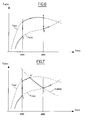
- FIG. 3 of the appended drawings represents an orthogonal coordinate system whose abscissa axis corresponds to a speed of rotation ⁇ (in revolutions per minute) and the axis ordinates to a couple C (in Newton. meters).
- the strategy underlying the invention consists in placing this point, as soon as possible, on a " C STAB " curve corresponding to a stabilized pipe.
- This optimal value is defined by a torque / speed map of the heat engine.
- the " C MAX” curve corresponds to the maximum possible torque of the heat engine.
- the value of C STAB is approximately 30% lower than that of C MAX .
- the losses in the electrical transmission are low.
- the curve P (4000) is a curve along which the power is constant. There are of course an infinity of similar curves.
- the curve shown is that which intersects the curve " C STAB " at the speed of 4000 rpm, this value being chosen in order to illustrate the operation of the invention subsequently.
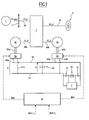
- the vehicle has an engine thermal 1, driving wheels 2, and a pair of electric machines 4a, 4b.
- the heat engine 1 and the two electric machines 4a and 4b are interconnected via a mechanical assembly 3.
- the latter can in particular be composed of two gear trains epicycloidals associated with a mechanical switching device, as described in the aforementioned application No. 01 15050, which can be referred to if necessary, both in terms of its structure and its operation.
- the heat engine 1 and the two electric machines 4a and 4b are connected to the mechanical assembly 3 via their respective output shaft 10, 40a and 40b.
- the shaft 10 carries a flywheel 11.
- C MTH is the torque available directly at the outlet of the heat engine, upstream of the flywheel 11, while C 1 denotes the torque supplied to the mechanical assembly 3, downstream of said flywheel.
- the reference torque of the assembly has been designated by the reference C2 mechanical 3.
- the output shaft 20 of the mechanical assembly 3 controls the wheels driving 2.
- Each electric machine 4a, 4b can function indifferently as a current generator (when rotated by the shaft associated 40) or as a motor (when electric power is supplied to it).
- C a and C b denote the values of the torques delivered respectively by each of the two electric machines 4a, 4b, and by ⁇ a and ⁇ b the rotational speeds of each of these machines, respectively.
- the two inverters 5a and 5b are interconnected, via from their continuous supply lines 60a-61a and 60b-61b to a bus 6, both of which lines have the references 60 and 61.
- this connection device does not include any power.
- V the voltage between lines 60 and 61 of the bus must be maintained at a constant value V , for example equal to 400 volts.
- V the nominal working value for an assembly formed by an inverter and an electric machine which is particularly suitable for this application.
- a capacitor 62 interposed between the two inverters 61a, 61b and connected to lines 60 and 61 ensures a small energy storage between the two inverters, necessary for their operation.
- This capacitor 62 can in particular be of the electrochemical type, dielectric film or ceramic.
- bus 6 is connected to a high converter voltage - low voltage 7 associated with the service battery, much higher voltage low, for example 42 volts.
- the converter 7 ensures the loading of the drums.
- This battery is protected from high voltage by diodes 71-72.
- a command and control device 8 provided with a computer, makes it possible to act on each of the inverters 5a, 5b, via control links 86a, 86b, shown in dashed arrows in FIG. 1.
- This device will be called 8 "electrical regulation module”.
- the electrical regulation module reacts and acts according to input instructions corresponding to determined values of the pairs C 1 and C 2, reference values designated Ref C 1 and Ref C 2, as will be explained below.
- the transmission device allows, via a switching member ad hoc, to connect one of the two electric machines, either directly to the wheels of the vehicle (according to a first mode of operation), either on the planet of one of the two planetary gear trains (in a second mode of operation).
- the first mode of operation is implemented for low transmission ratios (for example between 0 and 15 km / h at 1000 rpm), especially for starting the vehicle.
- the second operating mode is used for relatively long transmission (for example between 15 and 60 km / h at a 1000 rpm), before and after starting.
- C WHEEL being the value of the torque on the wheel shaft.
- C 1 must not exceed C STAB because, on the one hand, the heat engine must not be stifled and, on the other hand, C 1 cannot be varied quickly to regulate the engine speed ( ⁇ MTH ), because this disturbs C 2.
- Ref C 1 must not be exceeded to avoid suffocating the heat engine.
- Ref C 2 must not be exceeded to avoid packing the vehicle.
- the Ref C 2 request if it is not immediately satisfied, is not because the value of C 1 is limited to C STAB .
- the object of the invention is therefore a mechanical regulation system of a power transmission device between, on the one hand, a heat engine provided with a flywheel and a pair of electric machines equipping a motor vehicle. and, on the other hand, its drive wheels, the heat engine being connected to the two electric machines by means of a mechanical assembly, for example to two epicyclic gear trains, while an electrical connection device located between the two electric machines ensure a direct passage of power from one machine to another, without any intermediate element for storing or releasing significant energy, this connection device being controlled in such a way that the power generated by one of the two electric machines is immediately consumed by the other, and so that the two electric machines meet the needs of the traction chain, the link ensuring the transfer of e electrical energy between the two electrical machines being made by means of two inverters, each of them being associated with an electrical machine, these two inverters being connected to a bus, the two lines of which are connected by a capacitor, a device known as " electric regulation module "being adapted to impose on each of said electric machines given values of
- C 1 and C 2 being respectively the values of the couples actually developed at the output of the heat engine, downstream of the flywheel and at the output of said mechanical assembly, on the drive wheel side, one enters as instructions in said electrical regulation module the desired reference values for each of these couples, designated Ref C 1 and, respectively, Ref C 2, from which the electrical regulation module will regulate the couples C a and C b.
- C WHEEL being the value of the torque measured or estimated on the wheel shaft
- C STAB is the value of the torque of the heat engine corresponding to a so-called “stabilized” pipe.
- this is defined by a torque / speed mapping of the engine.
- this system comprises a circuit comprising two control loops for a control computer of the torque C MTH of the heat engine, namely a first loop which takes the information C WHEEL at the output of said power transmission chain and compares it with the value of Ref C WHEEL by means of a first and a second loop which takes the information ⁇ MTH at the output of a transfer function placed downstream of said chain of power transmission and compares it with the value of Ref ⁇ MTH by means of a second comparator, these first and second comparators being connected, each by means of a corrector, to the same switch, which is connected to the entry of said computer.
- this system comprises a circuit comprising two loops which take the information ⁇ MTH at the output of a transfer function placed downstream of said power transmission chain, namely a first loop adapted to compare this information with the value of Ref ⁇ MTH by means of a first comparator, and to deduce therefrom via a corrector, the value Ref C 1 and to enter it into said electrical regulation module, and a second loop adapted to send the information ⁇ MTH to a divider which also receives as information the power reference value Ref P MTH requested from the heat engine, so as to deliver a correct reference value Ref C MTH for the torque of the heat engine, and to send it to a C MTH torque engine control computer.
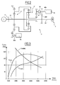
- Figures 4 and 5 are diagrams functional showing two possible control circuits, likely to be used for the implementation of the invention.
- FIGS. 6 and 7 are diagrams similar to that of FIG. 3 which illustrate two possible paths in the reference C MTH ( ⁇ MTH ), depending on whether the regulation is made using the circuit of FIG. 4 or, respectively, from that of figure 5.
- the module 8 receives instructions from the outside, by input lines Ref C 1 and Ref C 2.
- Ref C 1 is provided by a mapping module Z, which defines the value of the torque of the heat engine in "stabilized” driving as a function of the actual value of the speed of the heat engine ⁇ MTH .
- Ref C 2 is provided in a manner which will be explained later.
- the rectangle 9 symbolizes a power transfer function of the transmission (determined by equations). Its inputs, three in number, receive the actual values of C a and C b, after regulation by the module 8, as well as the value of the output torque of the heat engine ( C MTH ), which is given to it by a dynamic module 90 engine intake.
- the latter is a torque control computer for the heat engine.
- the power transfer function 9 is adapted to provide the values of C WHEEL and [ C MTH - C 1].
- a second transfer function 91 comprising in particular an integrator, determines from C WHEEL (taking into account the inertia of the vehicle) the value of ⁇ WHEEL .
- C WHEEL The value of C WHEEL is sent to a comparator 97.
- a third transfer function 92 determines from [ C MTH - C 1] (taking into account the inertia of the heat engine) the value of ⁇ MTH .
- the torque setpoint at the wheel Ref C WHEEL which is a function of the depressing angle of the accelerator pedal, is sent both to the aforementioned comparator 97, to a comparator 930 whose role will be explained below, and to a multiplier 94.
- the latter provides a power value to the wheel which is the product of Ref C WHEEL by ⁇ WHEEL .
- This value is addressed to the Z mapping module and processed by it. It outputs the speed value requested from the heat engine, Ref ⁇ MTH , which is addressed to comparator 96 which was mentioned above.
- the comparator 97 has the function of comparing the values of Ref C WHEEL and C WHEEL . In the event of a deviation, an action instruction on C 1 is sent, via a command corrector 901 to the switch link 903.
- the module 90 permanently receives a correct reference value for C MTH , selectively, from the corrector 901 or 902, via the switch 903.
- Ref C MTH is addressed via a gain 93 to an adder 930.
- the latter adds Ref C WHEEL to the value received from gain 93, and deduces the value of Ref C 2 therefrom, in order to send it to the electrical regulation module 8.
- This regulation can be found in two states. As long as the regulation can stay in the previous state, it stays there.
- Ref C MTH is used to regulate C WHEEL .
- the switch 903 then connects 901 to 90.
- Such a circuit makes it possible to obtain a pipe as illustrated on the figure 6.
- the revving and ordinary driving are ideally along the C STAB curve, incorporated in the Z mapping module.
- This line in fact corresponds to fuel consumption scaled down.
- the duration of the phases going from I to J and from K to L is almost instantaneous, of the order of 50 milliseconds each; that of phase J to K is of the order of 500 milliseconds (0.5 s).
- References 920 and 921 respectively designate a comparator and a corrector whose function is to minimize the difference between Ref ⁇ MTH and ⁇ MTH .
- the reference 98 designates a divider operator 1 / ⁇ MTH ⁇
- Such a circuit makes it possible to obtain a pipe as illustrated on the figure 7.
- the revving and ordinary driving are ideally along the C STAB curve, which corresponds to reduced fuel consumption.
- the function of the corrector 921 is to regulate the speed of the heat engine. Indeed, if its speed is insufficient compared to the setpoint, it reduces Ref C 1 of its load torque to allow it to increase the speed.
- the duration of the phase from I to J is almost instantaneous, of the order of 50 milliseconds; those of phases J to K ' and K' to L are of the order of 500 milliseconds (0.5 s) each.
- the second (figure 5) indicates the objective of ⁇ MTH to be reached according to the power of the heat engine which is required at the wheel.
Landscapes
- Engineering & Computer Science (AREA)
- Chemical & Material Sciences (AREA)
- Combustion & Propulsion (AREA)
- Transportation (AREA)
- Mechanical Engineering (AREA)
- Automation & Control Theory (AREA)
- Electric Propulsion And Braking For Vehicles (AREA)
- Hybrid Electric Vehicles (AREA)
- Control Of Vehicle Engines Or Engines For Specific Uses (AREA)
- Control Of Transmission Device (AREA)
Abstract
Description
Claims (5)
- Système de régulation mécanique d'un dispositif de transmission de puissance entre, d'une part, le moteur thermique (1) pourvu d'un volant d'inertie (11) et une paire de machines électriques (4a, 4b) équipant un véhicule automobile et, d'autre part, ses roues motrices (2), le moteur thermique (1) étant relié aux deux machines électriques (4a, 4b) par l'intermédiaire d'un ensemble mécanique (3), tandis qu'un dispositif de liaison électrique (6, 60a ; 61a-60b ; 61b, 5a-5b ; 50a-50b) situé entre les deux machines électriques assure un passage direct de puissance d'une machine à l'autre, sans élément intermédiaire de stockage ou de déstockage d'énergie important, ce dispositif de liaison (6, 60a ; 61a-60b ; 61b, 5a-5b ; 50a-50b) étant contrôlé de telle façon que la puissance générée par l'une (4a ; 4b) des deux machines électriques soit immédiatement consommée par l'autre (4b ; 4a), et pour que les deux machines électriques (4a, 4b) répondent aux besoins de la chaíne de traction, la liaison assurant le transfert d'énergie électrique entre les deux machines électriques se faisant par l'intermédiaire de deux onduleurs (5a, 5b), chacun d'eux étant associé à une machine électrique (4a, 4b), ces deux onduleurs étant connectés à un bus (6) dont les deux lignes sont reliées par un condensateur (62), un dispositif (8) dit "module de régulation électrique" étant adapté pour imposer à chacune desdites machines électriques (4a, 4b) des valeurs données de couple Ca, respectivement Cb, caractérisé par le fait que, C1 et C2 étant respectivement les valeurs des couples effectivement développés en sortie du moteur thermique, en aval dudit volant d'inertie (11) et en sortie dudit ensemble mécanique (3), côté roues motrices (2), on rentre comme consignes dans ledit module de régulation électrique (8) les valeurs de référence souhaitées pour chacun de ces couples, désignés Ref C1 et, respectivement, Ref C2, à partir desquelles le module de régulation électrique va réguler les couples Ca et Cb.
- Système de régulation mécanique selon la revendication 1, caractérisé par le fait qu'il comporte un circuit de commande (8) et une chaíne de transmission de puissance (9) adaptés pour générer lesdites valeurs de consigne Ref C1 et Ref C2, pour que soient en permanences respectées les conditions suivantes: C1 ≤ Ref C1 = C STAB et C ROUE = C2 ≤ Ref. C2, "C ROUE " étant la valeur du couple mesuré ou estimé sur l'arbre de roue, tandis que "C STAB" est la valeur du couple du moteur thermique (1) correspondant à une conduite dite "stabilisée".
- Système de régulation mécanique selon la revendication 2, caractérisé par le fait qu'il comporte un circuit comprenant deux boucles de pilotage d'un calculateur (90) de commande du couple C MTH du moteur thermique, à savoir une première boucle qui prélève l'information C ROUE à la sortie de ladite chaíne de transmission de puissance (9) et la compare avec la valeur de Ref C ROUE au moyen d'un premier comparateur (97) et une seconde boucle qui prélève l'information ωMTH à la sortie d'une fonction de transfert (92) placée en aval de ladite chaíne de transmission de puissance (9) et la compare avec la valeur de Ref ωMTH au moyen d'un second comparateur (96), ces premier et second comparateurs (97, 96) étant reliés, chacun par l'intermédiaire d'un correcteur (901, respectivement 902) à un même commutateur (903), lequel est connecté à l'entrée dudit calculateur (90).
- Système de régulation mécanique selon la revendication 2, caractérisé par le fait qu'il comporte un circuit comprenant deux boucles qui prélèvent l'information ωMTH à la sortie d'une fonction de transfert (92) placée en aval de ladite chaíne de transmission de puissance (9), à savoir une première boucle adaptée pour comparer cette information avec la valeur de Ref ωMTH au moyen d'un premier comparateur (920), et pour en déduire via un correcteur (921), la valeur Ref C1 et pour la rentrer dans ledit module de régulation électrique (8), et une seconde boucle adaptée pour adresser l'information ωMTH à un diviseur (98) qui reçoit également comme information la valeur de référence de puissance Ref P MTH demandée au moteur thermique, de manière à délivrer une valeur de consigne correcte Ref C MTH pour le couple du moteur thermique, et pour l'adresser à un calculateur (90) de commande du couple C MTH du moteur thermique.
- Système de régulation mécanique selon l'une des revendications 1 à 4, caractérisé par le fait que ladite valeur du couple du moteur thermique (1) correspondant à une conduite dite "stabilisée" est définie par une cartographie couple/vitesse du moteur thermique (1).
Applications Claiming Priority (2)
| Application Number | Priority Date | Filing Date | Title |
|---|---|---|---|
| FR0302338A FR2851515B1 (fr) | 2003-02-26 | 2003-02-26 | Systeme de regulation mecanique du dispositif de transmission de mouvement pour un vehicule automobile |
| FR0302338 | 2003-02-26 |
Publications (2)
| Publication Number | Publication Date |
|---|---|
| EP1452383A1 true EP1452383A1 (fr) | 2004-09-01 |
| EP1452383B1 EP1452383B1 (fr) | 2006-06-21 |
Family
ID=32749725
Family Applications (1)
| Application Number | Title | Priority Date | Filing Date |
|---|---|---|---|
| EP04364019A Expired - Lifetime EP1452383B1 (fr) | 2003-02-26 | 2004-02-25 | Système de régulation mécanique du dispositif de transmission de mouvement pour un véhicule automobile |
Country Status (5)
| Country | Link |
|---|---|
| EP (1) | EP1452383B1 (fr) |
| AT (1) | ATE331165T1 (fr) |
| DE (1) | DE602004001243T2 (fr) |
| ES (1) | ES2270322T3 (fr) |
| FR (1) | FR2851515B1 (fr) |
Cited By (3)
| Publication number | Priority date | Publication date | Assignee | Title |
|---|---|---|---|---|
| FR2912694A1 (fr) * | 2007-02-21 | 2008-08-22 | Renault Sas | Transmission a derivation de puissance a machine electrique independante. |
| WO2013068808A1 (fr) * | 2011-11-10 | 2013-05-16 | Toyota Jidosha Kabushiki Kaisha | Véhicule et procédé de commande de véhicule |
| WO2013076566A1 (fr) * | 2011-11-24 | 2013-05-30 | Toyota Jidosha Kabushiki Kaisha | Véhicule et procédé de commande pour véhicule |
Families Citing this family (1)
| Publication number | Priority date | Publication date | Assignee | Title |
|---|---|---|---|---|
| FR2875745B1 (fr) * | 2004-09-24 | 2008-03-21 | Peugeot Citroen Automobiles Sa | Procede de regulation pour un dispositif de transmission entre un arbre d'un moteur thermique et un arbre de roues d'un vehicule |
Citations (5)
| Publication number | Priority date | Publication date | Assignee | Title |
|---|---|---|---|---|
| EP0830969A2 (fr) * | 1996-09-24 | 1998-03-25 | Toyota Jidosha Kabushiki Kaisha | Système d'entraínement et méthode de commande |
| FR2783763A1 (fr) * | 1998-09-30 | 2000-03-31 | Renault | Groupe motopropulseur comportant un moteur thermique regule en couple et en vitesse |
| US20010017227A1 (en) * | 1999-04-27 | 2001-08-30 | Masahiko Amano | Hybrid vehicle |
| EP1275551A1 (fr) * | 2001-07-12 | 2003-01-15 | Renault s.a.s. | Dispositif de contrôle du point de fonctionnement du groupe motopropulseur d'un véhicule |
| WO2003024735A2 (fr) * | 2001-09-17 | 2003-03-27 | Renault S.A.S. | Moyens de commande pour une transmission a derivation de puissance |
-
2003
- 2003-02-26 FR FR0302338A patent/FR2851515B1/fr not_active Expired - Fee Related
-
2004
- 2004-02-25 DE DE602004001243T patent/DE602004001243T2/de not_active Expired - Lifetime
- 2004-02-25 ES ES04364019T patent/ES2270322T3/es not_active Expired - Lifetime
- 2004-02-25 EP EP04364019A patent/EP1452383B1/fr not_active Expired - Lifetime
- 2004-02-25 AT AT04364019T patent/ATE331165T1/de not_active IP Right Cessation
Patent Citations (5)
| Publication number | Priority date | Publication date | Assignee | Title |
|---|---|---|---|---|
| EP0830969A2 (fr) * | 1996-09-24 | 1998-03-25 | Toyota Jidosha Kabushiki Kaisha | Système d'entraínement et méthode de commande |
| FR2783763A1 (fr) * | 1998-09-30 | 2000-03-31 | Renault | Groupe motopropulseur comportant un moteur thermique regule en couple et en vitesse |
| US20010017227A1 (en) * | 1999-04-27 | 2001-08-30 | Masahiko Amano | Hybrid vehicle |
| EP1275551A1 (fr) * | 2001-07-12 | 2003-01-15 | Renault s.a.s. | Dispositif de contrôle du point de fonctionnement du groupe motopropulseur d'un véhicule |
| WO2003024735A2 (fr) * | 2001-09-17 | 2003-03-27 | Renault S.A.S. | Moyens de commande pour une transmission a derivation de puissance |
Cited By (7)
| Publication number | Priority date | Publication date | Assignee | Title |
|---|---|---|---|---|
| FR2912694A1 (fr) * | 2007-02-21 | 2008-08-22 | Renault Sas | Transmission a derivation de puissance a machine electrique independante. |
| WO2013068808A1 (fr) * | 2011-11-10 | 2013-05-16 | Toyota Jidosha Kabushiki Kaisha | Véhicule et procédé de commande de véhicule |
| CN103917391A (zh) * | 2011-11-10 | 2014-07-09 | 丰田自动车株式会社 | 车辆和车辆控制方法 |
| CN103917391B (zh) * | 2011-11-10 | 2016-05-04 | 丰田自动车株式会社 | 车辆和车辆控制方法 |
| WO2013076566A1 (fr) * | 2011-11-24 | 2013-05-30 | Toyota Jidosha Kabushiki Kaisha | Véhicule et procédé de commande pour véhicule |
| CN103958243A (zh) * | 2011-11-24 | 2014-07-30 | 丰田自动车株式会社 | 车辆和用于车辆的控制方法 |
| CN103958243B (zh) * | 2011-11-24 | 2016-11-02 | 丰田自动车株式会社 | 车辆和用于车辆的控制方法 |
Also Published As
| Publication number | Publication date |
|---|---|
| EP1452383B1 (fr) | 2006-06-21 |
| DE602004001243T2 (de) | 2007-05-03 |
| FR2851515A1 (fr) | 2004-08-27 |
| ATE331165T1 (de) | 2006-07-15 |
| ES2270322T3 (es) | 2007-04-01 |
| DE602004001243D1 (de) | 2006-08-03 |
| FR2851515B1 (fr) | 2006-01-20 |
Similar Documents
| Publication | Publication Date | Title |
|---|---|---|
| EP0652835B1 (fr) | Vehicule automobile a traction electrique | |
| EP2885147B1 (fr) | Procede de limitation de couple d'une machine electrique de vehicule hybride comportant un systeme de controle de vitesse | |
| FR2768480A1 (fr) | Procede et dispositif pour reduire le bruit de battement dans un mecanisme a engrenages | |
| FR2780921A1 (fr) | Dispositif de sortie motrice et son procede de controle et vehicule hybride actionne par le dispositif de sortie motrice | |
| EP1428712A1 (fr) | Chaíne de traction et procedé de réglage pour véhicule hybride série | |
| WO2014027152A1 (fr) | Procede de limitation de couple d'une machine electrique de vehicule hybride, dans le cas d'une forte demande en couple | |
| FR2956637A1 (fr) | Procede de gestion d'un systeme d'entrainement pour vehicule automobile | |
| WO2011064095A2 (fr) | Onduleur de pilotage d'un moteur electrique comportant un regulateur integre | |
| FR2843339A1 (fr) | Systeme de commande du regime de ralenti pour un vehicule hybride | |
| FR2869075A1 (fr) | Dispositif de demarrage-arret automatique pour un moteur a combustion interne et vehicule a moteur electrique equipe d'un dispositif de demarrage-arret automatique | |
| EP1241043A1 (fr) | Véhicule hybride série capable de fonctionner sans batterie | |
| US20090163317A1 (en) | Power Output Apparatus, Vehicle Provided With the Same, and Method of Controlling the Same | |
| FR2856109A1 (fr) | Systeme de commande de puissance pour un vehicule sur lequel est monte un moteur avec turbocompresseur | |
| EP2928746A1 (fr) | Procede de controle de couples lors du demarrage du moteur thermique d'un vehicule hybride, pour passer d'un mode electrique a un mode hybride | |
| EP2044315B1 (fr) | Procede de gestion d'un couple applique a un arbre de sortie d'un moteur thermique lors d'une desactivation d'une chambre de combustion et systeme de gestion correspondant | |
| WO2001025049A1 (fr) | Procede de commande d'un vehicule hybride | |
| EP1452383B1 (fr) | Système de régulation mécanique du dispositif de transmission de mouvement pour un véhicule automobile | |
| FR2465884A1 (fr) | Groupe propulseur pour vehicule automobile utilisant un moteur thermique jusqu'aux plus bas regimes | |
| EP1542882A2 (fr) | Procede et dispositif de transmission de puissance pour un vehicule hybride | |
| EP1565340A2 (fr) | Systeme de regulation electrique du dispositif de transmission de mouvement pour un vehicule automobile | |
| FR2954257A1 (fr) | Groupe motopropulseur hybride. | |
| EP0678414B1 (fr) | Véhicule hybride | |
| FR3000713A1 (fr) | Procede et systeme de correction d’oscillations de regime d’un train roulant | |
| WO2009115719A2 (fr) | Procede de commande d'un ensemble moteur muni d'un alternateur reversible et d'un variateur de vitesse et ensemble moteur associe | |
| FR2967619A1 (fr) | Vehicule hybride a deux trains d'engrenages epicycloidaux a efficacite energetique amelioree |
Legal Events
| Date | Code | Title | Description |
|---|---|---|---|
| PUAI | Public reference made under article 153(3) epc to a published international application that has entered the european phase |
Free format text: ORIGINAL CODE: 0009012 |
|
| AK | Designated contracting states |
Kind code of ref document: A1 Designated state(s): AT BE BG CH CY CZ DE DK EE ES FI FR GB GR HU IE IT LI LU MC NL PT RO SE SI SK TR |
|
| AX | Request for extension of the european patent |
Extension state: AL HR LT LV MK |
|
| 17P | Request for examination filed |
Effective date: 20050223 |
|
| R17P | Request for examination filed (corrected) |
Effective date: 20050223 |
|
| AKX | Designation fees paid |
Designated state(s): AT BE BG CH CY CZ DE DK EE ES FI FR GB GR HU IE IT LI LU MC NL PT RO SE SI SK TR |
|
| GRAP | Despatch of communication of intention to grant a patent |
Free format text: ORIGINAL CODE: EPIDOSNIGR1 |
|
| RIC1 | Information provided on ipc code assigned before grant |
Ipc: F16H 3/72 20060101ALI20060116BHEP Ipc: F16H 61/66 20060101AFI20060116BHEP Ipc: B60K 6/02 20060101ALI20060116BHEP |
|
| GRAS | Grant fee paid |
Free format text: ORIGINAL CODE: EPIDOSNIGR3 |
|
| GRAA | (expected) grant |
Free format text: ORIGINAL CODE: 0009210 |
|
| AK | Designated contracting states |
Kind code of ref document: B1 Designated state(s): AT BE BG CH CY CZ DE DK EE ES FI FR GB GR HU IE IT LI LU MC NL PT RO SE SI SK TR |
|
| PG25 | Lapsed in a contracting state [announced via postgrant information from national office to epo] |
Ref country code: RO Free format text: LAPSE BECAUSE OF FAILURE TO SUBMIT A TRANSLATION OF THE DESCRIPTION OR TO PAY THE FEE WITHIN THE PRESCRIBED TIME-LIMIT Effective date: 20060621 Ref country code: CZ Free format text: LAPSE BECAUSE OF FAILURE TO SUBMIT A TRANSLATION OF THE DESCRIPTION OR TO PAY THE FEE WITHIN THE PRESCRIBED TIME-LIMIT Effective date: 20060621 Ref country code: IT Free format text: LAPSE BECAUSE OF FAILURE TO SUBMIT A TRANSLATION OF THE DESCRIPTION OR TO PAY THE FEE WITHIN THE PRESCRIBED TIME-LIMIT;WARNING: LAPSES OF ITALIAN PATENTS WITH EFFECTIVE DATE BEFORE 2007 MAY HAVE OCCURRED AT ANY TIME BEFORE 2007. THE CORRECT EFFECTIVE DATE MAY BE DIFFERENT FROM THE ONE RECORDED. Effective date: 20060621 Ref country code: FI Free format text: LAPSE BECAUSE OF FAILURE TO SUBMIT A TRANSLATION OF THE DESCRIPTION OR TO PAY THE FEE WITHIN THE PRESCRIBED TIME-LIMIT Effective date: 20060621 Ref country code: SK Free format text: LAPSE BECAUSE OF FAILURE TO SUBMIT A TRANSLATION OF THE DESCRIPTION OR TO PAY THE FEE WITHIN THE PRESCRIBED TIME-LIMIT Effective date: 20060621 Ref country code: IE Free format text: LAPSE BECAUSE OF FAILURE TO SUBMIT A TRANSLATION OF THE DESCRIPTION OR TO PAY THE FEE WITHIN THE PRESCRIBED TIME-LIMIT Effective date: 20060621 Ref country code: AT Free format text: LAPSE BECAUSE OF FAILURE TO SUBMIT A TRANSLATION OF THE DESCRIPTION OR TO PAY THE FEE WITHIN THE PRESCRIBED TIME-LIMIT Effective date: 20060621 Ref country code: SI Free format text: LAPSE BECAUSE OF FAILURE TO SUBMIT A TRANSLATION OF THE DESCRIPTION OR TO PAY THE FEE WITHIN THE PRESCRIBED TIME-LIMIT Effective date: 20060621 Ref country code: NL Free format text: LAPSE BECAUSE OF FAILURE TO SUBMIT A TRANSLATION OF THE DESCRIPTION OR TO PAY THE FEE WITHIN THE PRESCRIBED TIME-LIMIT Effective date: 20060621 |
|
| REG | Reference to a national code |
Ref country code: GB Ref legal event code: FG4D Free format text: NOT ENGLISH |
|
| REG | Reference to a national code |
Ref country code: CH Ref legal event code: EP |
|
| REG | Reference to a national code |
Ref country code: IE Ref legal event code: FG4D Free format text: LANGUAGE OF EP DOCUMENT: FRENCH |
|
| REF | Corresponds to: |
Ref document number: 602004001243 Country of ref document: DE Date of ref document: 20060803 Kind code of ref document: P |
|
| PG25 | Lapsed in a contracting state [announced via postgrant information from national office to epo] |
Ref country code: SE Free format text: LAPSE BECAUSE OF FAILURE TO SUBMIT A TRANSLATION OF THE DESCRIPTION OR TO PAY THE FEE WITHIN THE PRESCRIBED TIME-LIMIT Effective date: 20060921 Ref country code: DK Free format text: LAPSE BECAUSE OF FAILURE TO SUBMIT A TRANSLATION OF THE DESCRIPTION OR TO PAY THE FEE WITHIN THE PRESCRIBED TIME-LIMIT Effective date: 20060921 |
|
| GBT | Gb: translation of ep patent filed (gb section 77(6)(a)/1977) |
Effective date: 20060924 |
|
| PG25 | Lapsed in a contracting state [announced via postgrant information from national office to epo] |
Ref country code: PT Free format text: LAPSE BECAUSE OF FAILURE TO SUBMIT A TRANSLATION OF THE DESCRIPTION OR TO PAY THE FEE WITHIN THE PRESCRIBED TIME-LIMIT Effective date: 20061121 |
|
| NLV1 | Nl: lapsed or annulled due to failure to fulfill the requirements of art. 29p and 29m of the patents act | ||
| REG | Reference to a national code |
Ref country code: IE Ref legal event code: FD4D |
|
| PG25 | Lapsed in a contracting state [announced via postgrant information from national office to epo] |
Ref country code: MC Free format text: LAPSE BECAUSE OF NON-PAYMENT OF DUE FEES Effective date: 20070228 |
|
| REG | Reference to a national code |
Ref country code: ES Ref legal event code: FG2A Ref document number: 2270322 Country of ref document: ES Kind code of ref document: T3 |
|
| PLBE | No opposition filed within time limit |
Free format text: ORIGINAL CODE: 0009261 |
|
| STAA | Information on the status of an ep patent application or granted ep patent |
Free format text: STATUS: NO OPPOSITION FILED WITHIN TIME LIMIT |
|
| 26N | No opposition filed |
Effective date: 20070322 |
|
| BERE | Be: lapsed |
Owner name: PEUGEOT CITROEN AUTOMOBILES S.A. Effective date: 20070228 |
|
| PG25 | Lapsed in a contracting state [announced via postgrant information from national office to epo] |
Ref country code: BE Free format text: LAPSE BECAUSE OF NON-PAYMENT OF DUE FEES Effective date: 20070228 |
|
| PG25 | Lapsed in a contracting state [announced via postgrant information from national office to epo] |
Ref country code: GR Free format text: LAPSE BECAUSE OF FAILURE TO SUBMIT A TRANSLATION OF THE DESCRIPTION OR TO PAY THE FEE WITHIN THE PRESCRIBED TIME-LIMIT Effective date: 20060922 |
|
| PG25 | Lapsed in a contracting state [announced via postgrant information from national office to epo] |
Ref country code: BG Free format text: LAPSE BECAUSE OF FAILURE TO SUBMIT A TRANSLATION OF THE DESCRIPTION OR TO PAY THE FEE WITHIN THE PRESCRIBED TIME-LIMIT Effective date: 20060921 |
|
| PG25 | Lapsed in a contracting state [announced via postgrant information from national office to epo] |
Ref country code: EE Free format text: LAPSE BECAUSE OF FAILURE TO SUBMIT A TRANSLATION OF THE DESCRIPTION OR TO PAY THE FEE WITHIN THE PRESCRIBED TIME-LIMIT Effective date: 20060621 |
|
| REG | Reference to a national code |
Ref country code: CH Ref legal event code: PL |
|
| PG25 | Lapsed in a contracting state [announced via postgrant information from national office to epo] |
Ref country code: CH Free format text: LAPSE BECAUSE OF NON-PAYMENT OF DUE FEES Effective date: 20080229 Ref country code: LI Free format text: LAPSE BECAUSE OF NON-PAYMENT OF DUE FEES Effective date: 20080229 |
|
| PG25 | Lapsed in a contracting state [announced via postgrant information from national office to epo] |
Ref country code: LU Free format text: LAPSE BECAUSE OF NON-PAYMENT OF DUE FEES Effective date: 20070225 Ref country code: CY Free format text: LAPSE BECAUSE OF FAILURE TO SUBMIT A TRANSLATION OF THE DESCRIPTION OR TO PAY THE FEE WITHIN THE PRESCRIBED TIME-LIMIT Effective date: 20060621 |
|
| PG25 | Lapsed in a contracting state [announced via postgrant information from national office to epo] |
Ref country code: TR Free format text: LAPSE BECAUSE OF FAILURE TO SUBMIT A TRANSLATION OF THE DESCRIPTION OR TO PAY THE FEE WITHIN THE PRESCRIBED TIME-LIMIT Effective date: 20060621 Ref country code: HU Free format text: LAPSE BECAUSE OF FAILURE TO SUBMIT A TRANSLATION OF THE DESCRIPTION OR TO PAY THE FEE WITHIN THE PRESCRIBED TIME-LIMIT Effective date: 20061222 |
|
| REG | Reference to a national code |
Ref country code: ES Ref legal event code: GC2A Effective date: 20110406 |
|
| PGFP | Annual fee paid to national office [announced via postgrant information from national office to epo] |
Ref country code: DE Payment date: 20140122 Year of fee payment: 11 |
|
| PGFP | Annual fee paid to national office [announced via postgrant information from national office to epo] |
Ref country code: ES Payment date: 20140122 Year of fee payment: 11 Ref country code: IT Payment date: 20140129 Year of fee payment: 11 |
|
| PGFP | Annual fee paid to national office [announced via postgrant information from national office to epo] |
Ref country code: GB Payment date: 20140127 Year of fee payment: 11 |
|
| REG | Reference to a national code |
Ref country code: DE Ref legal event code: R119 Ref document number: 602004001243 Country of ref document: DE |
|
| GBPC | Gb: european patent ceased through non-payment of renewal fee |
Effective date: 20150225 |
|
| PG25 | Lapsed in a contracting state [announced via postgrant information from national office to epo] |
Ref country code: IT Free format text: LAPSE BECAUSE OF NON-PAYMENT OF DUE FEES Effective date: 20150225 |
|
| REG | Reference to a national code |
Ref country code: FR Ref legal event code: PLFP Year of fee payment: 13 |
|
| PG25 | Lapsed in a contracting state [announced via postgrant information from national office to epo] |
Ref country code: GB Free format text: LAPSE BECAUSE OF NON-PAYMENT OF DUE FEES Effective date: 20150225 Ref country code: DE Free format text: LAPSE BECAUSE OF NON-PAYMENT OF DUE FEES Effective date: 20150901 |
|
| REG | Reference to a national code |
Ref country code: ES Ref legal event code: FD2A Effective date: 20160329 |
|
| PG25 | Lapsed in a contracting state [announced via postgrant information from national office to epo] |
Ref country code: ES Free format text: LAPSE BECAUSE OF NON-PAYMENT OF DUE FEES Effective date: 20150226 |
|
| PGFP | Annual fee paid to national office [announced via postgrant information from national office to epo] |
Ref country code: FR Payment date: 20160121 Year of fee payment: 13 |
|
| REG | Reference to a national code |
Ref country code: FR Ref legal event code: ST Effective date: 20171031 |
|
| PG25 | Lapsed in a contracting state [announced via postgrant information from national office to epo] |
Ref country code: FR Free format text: LAPSE BECAUSE OF NON-PAYMENT OF DUE FEES Effective date: 20170228 |