EP1452351A2 - MacPherson strut assembly - Google Patents
MacPherson strut assembly Download PDFInfo
- Publication number
- EP1452351A2 EP1452351A2 EP04250669A EP04250669A EP1452351A2 EP 1452351 A2 EP1452351 A2 EP 1452351A2 EP 04250669 A EP04250669 A EP 04250669A EP 04250669 A EP04250669 A EP 04250669A EP 1452351 A2 EP1452351 A2 EP 1452351A2
- Authority
- EP
- European Patent Office
- Prior art keywords
- spring
- isolator
- assembly according
- rod
- supported
- Prior art date
- Legal status (The legal status is an assumption and is not a legal conclusion. Google has not performed a legal analysis and makes no representation as to the accuracy of the status listed.)
- Withdrawn
Links
Images

Classifications
-
- F—MECHANICAL ENGINEERING; LIGHTING; HEATING; WEAPONS; BLASTING
- F16—ENGINEERING ELEMENTS AND UNITS; GENERAL MEASURES FOR PRODUCING AND MAINTAINING EFFECTIVE FUNCTIONING OF MACHINES OR INSTALLATIONS; THERMAL INSULATION IN GENERAL
- F16F—SPRINGS; SHOCK-ABSORBERS; MEANS FOR DAMPING VIBRATION
- F16F1/00—Springs
- F16F1/02—Springs made of steel or other material having low internal friction; Wound, torsion, leaf, cup, ring or the like springs, the material of the spring not being relevant
- F16F1/04—Wound springs
- F16F1/12—Attachments or mountings
- F16F1/126—Attachments or mountings comprising an element between the end coil of the spring and the support proper, e.g. an elastomeric annulus
-
- B—PERFORMING OPERATIONS; TRANSPORTING
- B60—VEHICLES IN GENERAL
- B60G—VEHICLE SUSPENSION ARRANGEMENTS
- B60G15/00—Resilient suspensions characterised by arrangement, location or type of combined spring and vibration damper, e.g. telescopic type
- B60G15/02—Resilient suspensions characterised by arrangement, location or type of combined spring and vibration damper, e.g. telescopic type having mechanical spring
- B60G15/06—Resilient suspensions characterised by arrangement, location or type of combined spring and vibration damper, e.g. telescopic type having mechanical spring and fluid damper
- B60G15/062—Resilient suspensions characterised by arrangement, location or type of combined spring and vibration damper, e.g. telescopic type having mechanical spring and fluid damper the spring being arranged around the damper
- B60G15/063—Resilient suspensions characterised by arrangement, location or type of combined spring and vibration damper, e.g. telescopic type having mechanical spring and fluid damper the spring being arranged around the damper characterised by the mounting of the spring on the damper
-
- F—MECHANICAL ENGINEERING; LIGHTING; HEATING; WEAPONS; BLASTING
- F16—ENGINEERING ELEMENTS AND UNITS; GENERAL MEASURES FOR PRODUCING AND MAINTAINING EFFECTIVE FUNCTIONING OF MACHINES OR INSTALLATIONS; THERMAL INSULATION IN GENERAL
- F16F—SPRINGS; SHOCK-ABSORBERS; MEANS FOR DAMPING VIBRATION
- F16F1/00—Springs
- F16F1/02—Springs made of steel or other material having low internal friction; Wound, torsion, leaf, cup, ring or the like springs, the material of the spring not being relevant
- F16F1/04—Wound springs
- F16F1/12—Attachments or mountings
- F16F1/13—Attachments or mountings comprising inserts and spacers between the windings for changing the mechanical or physical characteristics of the spring
-
- F—MECHANICAL ENGINEERING; LIGHTING; HEATING; WEAPONS; BLASTING
- F16—ENGINEERING ELEMENTS AND UNITS; GENERAL MEASURES FOR PRODUCING AND MAINTAINING EFFECTIVE FUNCTIONING OF MACHINES OR INSTALLATIONS; THERMAL INSULATION IN GENERAL
- F16F—SPRINGS; SHOCK-ABSORBERS; MEANS FOR DAMPING VIBRATION
- F16F2224/00—Materials; Material properties
- F16F2224/005—Combined materials of same basic nature but differing characteristics
Definitions
- This invention relates to a MacPherson strut assembly, and more particularly, the invention relates to spring seat isolators for supporting a spring of a MacPherson strut assembly.
- MacPherson struts are used in many suspension systems and are arranged between the frame and a lower control arm.
- a wheel end is attached to the strut at the lower control arm.
- the strut includes a hydraulic cylinder with a fluid chamber, and a piston is arranged in the chamber for moving through the fluid and damping the motion of the wheel end.
- a rod is attached to the piston and extends from the hydraulic cylinder.
- a coil spring is arranged between an upper spring seat supported on the rod and a lower spring seat supported on the hydraulic cylinder. The spring provides a desired spring rate for the wheel end.
- the present invention provides a MacPherson strut assembly that has a hydraulic cylinder with a fluid chamber.
- a piston is arranged in the chamber, and a rod extends from the piston.
- a lower spring seat is supported on the hydraulic cylinder, and an upper spring seat is supported on the rod.
- a coil spring is arranged between the spring seats to produce a desired spring loading.
- a compliant isolator having a sloped profile is arranged on the lower spring seat to produce an uneven spring loading.
- a spring seat isolator may include materials of a different stiffness to produce uneven spring loading. An isolator may also be used between coils of the spring so that the compression on one side of the spring is limited more that the opposite side to produce uneven loading.
- the above invention provides a lightweight, inexpensive strut that generates uneven spring loading to produce a counteracting moment.
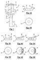
- a strut 10 is schematically shown in Figure 1.
- the strut 10 includes a hydraulic cylinder 12 with a fluid chamber that has a piston 14 disposed therein, as is known in the art.
- a rod 16 extends from the piston 14 and is supported by the hydraulic cylinder 12 by a cylinder head (not shown).
- the hydraulic cylinder 12 includes an attachment 17 for receiving a knuckle that supports a wheel end. In a typical strut assembly, a side load is generated between the rod 16 and piston 14 and the hydraulic cylinder 12 due to moments on the strut 10.
- An upper spring seat 18 is supported on the rod 16, and the hydraulic cylinder 12 supports a lower spring seat 20.
- a coil spring 26 is arranged between the spring seats 18, 20 and produces a spring loading.
- Compliant rubber or urethane isolators 22, 24 may be used between the spring 26 and the spring seats 18, 20.
- Prior art isolators have a uniform thickness and are used to reduce strut noise.
- At least one present invention isolator, preferably the lower, is used in conjunction with a spring seat that is attached generally normal to the strut centerline.
- the isolators may be inexpensively molded to any desired shape using any suitable material.
- the present invention isolator 24 includes a sloped surface 32 that curves from a first portion 30 upward toward a second portion 28, best shown in Figures 2A-5B, to generate uneven spring loading to produce a counteracting moment.
- the first portion 30 has a first thickness 34 that is less than a second thickness 36 of the second portion.
- the spring 26 is compressed to a shorter length Ll on one side producing a greater spring force than on the opposing side, which has a length L2.
- the surface 32 may have a sharp curve, as shown in Figures 2A-2B, or a more gentle, sloping curve, as shown in Figures 3A-3B.
- one or more arcuate ridges 38, 40 may extend outwardly from the isolator 24 to reduce the weight and cost of the isolator.
- the ridges 38, 40 may extend circumferentially about a large portion of the isolator, or a reduced portion of the isolator, as shown in Figures 5A-5B.
- the size, shape, and location of the thicker portion of the isolator may be determined based upon the particular strut geometry and loading.
- An isolator 39 includes a first portion 41 having a first stiffness k1.
- a second portion 43 has a second stiffness k2 that is stiffer that the material used for the first portion 41.
- the second portion may extend to the perimeter 42 of the isolator, as shown in Figure 6, or may be spaced from the perimeter 42, as shown in Figure 7.
- a number of second portions 44, 46 may be arranged in an arcuate pattern to provide an effect similar to that shown in Figures 4A-5B. Increasingly stiffer materials may be used as the radial distance is increased.
- the first and second portions of the isolator of figures 6, 7 or 8 have substantially the same thickness.
- an isolator may be used between first and second coils 48, 50 of the spring 26.
- the isolator keeps the coils 48, 50 spaced farther apart on one side 52 than the other side to generate uneven spring loading.
- an isolator having a wedge-shaped cross-section may be arranged between the coils 48, 50.
- one or more C-shaped isolators 58 may be clipped to the coils of the spring 26.
Landscapes
- Engineering & Computer Science (AREA)
- General Engineering & Computer Science (AREA)
- Mechanical Engineering (AREA)
- Springs (AREA)
- Fluid-Damping Devices (AREA)
- Vehicle Body Suspensions (AREA)
Abstract
Description
Claims (14)
- A MacPherson strut assembly (10) comprising:a hydraulic cylinder (12) having a fluid chamber with a piston (14) disposed therein and a rod (16) extending from said piston;a lower spring seat (20) supported on said hydraulic cylinder;an upper spring seat (18) supported on said rod;a coil spring (26) arranged between said spring seats; anda compliant isolator (24) supported on one of said spring seats between said spring and said one of said spring seats, said isolator having a first portion (30) defining a first vertical length to said other of said spring seats and a second portion (28) raised relative to said first portion defining a second vertical length to said other of said spring seats, said second vertical length less than said first vertical length.
- The assembly according to claim 1, wherein said isolator includes a curved surface (32) supporting said spring, and a first thickness (34) defining said first portion and a second thickness (36) defining said second portion with said first thickness less than said second thickness.
- The assembly according to claim 1 or 2, wherein at least one arcuate ridge (38, 40) extending away from said one of said spring seats defines said second portion.
- The assembly according to claim 3, wherein said arcuate ridge extends circumferentially less than 180° in spaced relation to said rod.
- The assembly according to any preceding claim, wherein said isolator is constructed from a rubber material, or a urethane material.
- The assembly according to any preceding claim, wherein said one of said seats is mounted generally normal to a strut centerline.
- A MacPherson strut assembly (10) comprising:a hydraulic cylinder (12) having a fluid chamber with a piston (14) disposed therein and a rod (16) extending from said piston;a lower spring seat (20) supported on said hydraulic cylinder;an upper spring seat (18) supported on said rod;a coil spring (26) arranged between said spring seats; andan isolator (39) supported on one of said spring seats between said spring and said one of said spring seats, said isolator having first (41) and second (43) portions respectively including first (K1) and second (K2) stiffnesses with said first stiffness less than said second stiffness, and said second stiffness creating a greater spring load at said second portion than a lesser spring load at said first portion.
- The assembly according to claim 8, wherein said first and second portions are respectively constructed from first and second materials that are different than one another.
- The assembly according to claim 7 or 8, wherein said first and second portions extend radially to a perimeter (42) of said isolator.
- The assembly according to claim 7 or 8, wherein one of said portions is spaced radially inward from a perimeter of said isolator.
- The assembly according to any one of claims 7 to 10, wherein said second portion is defined by at least one arcuate segment spaced from said rod.
- A MacPherson strut assembly (10) comprising:a hydraulic cylinder (12) having a fluid chamber with a piston (14) disposed therein and a rod (16) extending from said piston;a lower spring seat (20) supported on said hydraulic cylinder;an upper spring seat (18) supported on said rod;a coil spring (26) arranged between said spring seats, said spring having first (48) and second (50) spaced apart coils with first and second opposing sides; andan isolator (56, 58) arranged between said first and second coils, said isolator defining a first distance between said coils on one side in a compressed spring state, and said isolator defining a second distance less than said first distance between said coils on said opposing side in said compressed spring state.
- The assembly according to claim 12, wherein said isolator has a wedge-shaped cross-section.
- The assembly according to claim 12, wherein said isolator has a generally C-shaped cross-section clamped about a portion at least one of said coils on said one side.
Applications Claiming Priority (2)
| Application Number | Priority Date | Filing Date | Title |
|---|---|---|---|
| US375971 | 1982-05-10 | ||
| US10/375,971 US20040169323A1 (en) | 2003-02-28 | 2003-02-28 | MacPherson strut spring coil mounts |
Publications (2)
| Publication Number | Publication Date |
|---|---|
| EP1452351A2 true EP1452351A2 (en) | 2004-09-01 |
| EP1452351A3 EP1452351A3 (en) | 2004-10-27 |
Family
ID=32771482
Family Applications (1)
| Application Number | Title | Priority Date | Filing Date |
|---|---|---|---|
| EP04250669A Withdrawn EP1452351A3 (en) | 2003-02-28 | 2004-02-09 | MacPherson strut assembly |
Country Status (3)
| Country | Link |
|---|---|
| US (1) | US20040169323A1 (en) |
| EP (1) | EP1452351A3 (en) |
| BR (1) | BRPI0400198A (en) |
Cited By (2)
| Publication number | Priority date | Publication date | Assignee | Title |
|---|---|---|---|---|
| FR2919034A1 (en) * | 2007-07-20 | 2009-01-23 | Woco Avs Sas | SUSPENSION SPRING-SPRING SYSTEM |
| EP1982857A4 (en) * | 2006-02-08 | 2010-12-08 | Nissan Motor | Spring seat of suspension |
Families Citing this family (2)
| Publication number | Priority date | Publication date | Assignee | Title |
|---|---|---|---|---|
| KR200412713Y1 (en) * | 2005-12-28 | 2006-03-31 | 삼송공업 주식회사 | Caster Shock Absorber |
| JP6475217B2 (en) * | 2016-11-04 | 2019-02-27 | 本田技研工業株式会社 | Spring seat rubber |
Family Cites Families (18)
| Publication number | Priority date | Publication date | Assignee | Title |
|---|---|---|---|---|
| US2807459A (en) * | 1953-11-17 | 1957-09-24 | Copeland Clayton Simpson | Resilience adjusting means for coil springs |
| US2904329A (en) * | 1954-09-01 | 1959-09-15 | Joseph Louis | Spring booster |
| JPS5813767B2 (en) * | 1979-08-22 | 1983-03-15 | 中央発條株式会社 | Coil spring seat |
| AU1442783A (en) * | 1982-05-10 | 1983-11-17 | Starr Rubber Mills Pty. Ltd. | Motor vehicle springs |
| DE3304321C2 (en) * | 1983-02-09 | 1985-02-21 | Horst 7730 Villingen-Schwenningen Klann | Spring tensioner |
| JPS6164506A (en) * | 1984-09-05 | 1986-04-02 | Nissan Motor Co Ltd | Strut type suspension |
| KR920001041Y1 (en) * | 1989-01-24 | 1992-02-10 | 현대자동차 주식회사 | Insulator structure of strut type suspension system for automobile |
| US4958849A (en) * | 1989-06-19 | 1990-09-25 | Saturn Corporation | Mounting assembly and method for a damper |
| DE4104859C1 (en) * | 1991-02-16 | 1992-07-09 | Dr.Ing.H.C. F. Porsche Ag, 7000 Stuttgart, De | |
| DE4211176C2 (en) * | 1992-04-03 | 1998-07-23 | Porsche Ag | Bearing for a shock absorber of a motor vehicle |
| US5467971A (en) * | 1994-08-08 | 1995-11-21 | General Motors Corporation | Strut assembly with integral bearing and spring seat |
| US5454585A (en) * | 1994-08-08 | 1995-10-03 | General Motors Corporation | Strut assembly with bearing axis alignment |
| DE19511642C2 (en) * | 1995-03-30 | 2002-08-01 | Zf Lemfoerder Metallwaren Ag | Upper strut support bearing for wheel suspensions in a motor vehicle |
| US5788262A (en) * | 1995-12-19 | 1998-08-04 | Chrysler Corporation | Rear suspension strut upper mount |
| DE69627116T2 (en) * | 1995-12-19 | 2003-12-24 | Compagnie Generale Des Etablissements Michelin-Michelin & Cie., Clermont-Ferrand | MacPherson strut fine adjustment: strut adjustment device and bench for measurement |
| EP0816140B1 (en) * | 1996-06-27 | 2002-11-27 | ZF Lemförder Metallwaren AG | Upper strut mount for a motor vehicle suspension |
| DE19939515C2 (en) * | 1999-08-20 | 2002-06-13 | Porsche Ag | Strut for a motor vehicle with a bearing for a coil spring |
| EP1172238A1 (en) * | 2000-07-12 | 2002-01-16 | Allevard Rejna Autosuspensions | Device for positioning an end of a coil spring for a suspension |
-
2003
- 2003-02-28 US US10/375,971 patent/US20040169323A1/en not_active Abandoned
-
2004
- 2004-02-09 EP EP04250669A patent/EP1452351A3/en not_active Withdrawn
- 2004-02-19 BR BR0400198-2A patent/BRPI0400198A/en not_active Application Discontinuation
Cited By (3)
| Publication number | Priority date | Publication date | Assignee | Title |
|---|---|---|---|---|
| EP1982857A4 (en) * | 2006-02-08 | 2010-12-08 | Nissan Motor | Spring seat of suspension |
| FR2919034A1 (en) * | 2007-07-20 | 2009-01-23 | Woco Avs Sas | SUSPENSION SPRING-SPRING SYSTEM |
| EP2017098A3 (en) * | 2007-07-20 | 2010-02-24 | anvis SD France S.A.S. | Association of a compression spring |
Also Published As
| Publication number | Publication date |
|---|---|
| US20040169323A1 (en) | 2004-09-02 |
| EP1452351A3 (en) | 2004-10-27 |
| BRPI0400198A (en) | 2004-12-28 |
Similar Documents
| Publication | Publication Date | Title |
|---|---|---|
| US9586456B2 (en) | Recuperating passive and active suspension | |
| EP0225271B1 (en) | Side load compensating air suspension | |
| US6776402B2 (en) | Liquid-encapsulated damper mount and hydraulic damper mounting structure in suspension of automobile | |
| US6830256B2 (en) | Method and apparatus for rebound control | |
| US9950583B2 (en) | Spring seat | |
| US8191692B2 (en) | Cylinder apparatus | |
| US9108483B2 (en) | Vehicle suspension comprising light weight leaf spring assembly | |
| JP3268454B2 (en) | Wheel suspension method and suspension device | |
| EP2233330A3 (en) | Active suspension system for vehicle | |
| CN105377594A (en) | Vehicle suspension and leaf spring therefore | |
| JPH10196700A (en) | Air spring strut for compensating lateral load and method for compensating lateral load | |
| WO2013085650A1 (en) | Spring seat having an installation land/step | |
| JP2002542974A (en) | Improved combination air spring shock absorber | |
| US4883288A (en) | Suspension strut with side load support | |
| EP0257779A2 (en) | Air spring damper for vehicle suspension | |
| EP1452351A2 (en) | MacPherson strut assembly | |
| US5163659A (en) | Hydraulic actuator for leveling system | |
| CN112930272B (en) | Damper with integral base | |
| US20080136076A1 (en) | Jounce Bumper Assembly | |
| CN100436173C (en) | Spring strut mounting for a vehicle wheel | |
| US20070164531A1 (en) | Method and apparatus for rebound control | |
| GB2418002A (en) | A strut assembly including a compression spring of non-linear shape | |
| JP3168856B2 (en) | Strut mount mounting structure | |
| US12337646B2 (en) | Vehicle suspension systems and methods | |
| WO2006101589A1 (en) | Air spring assembly with flexible can |
Legal Events
| Date | Code | Title | Description |
|---|---|---|---|
| PUAI | Public reference made under article 153(3) epc to a published international application that has entered the european phase |
Free format text: ORIGINAL CODE: 0009012 |
|
| AK | Designated contracting states |
Kind code of ref document: A2 Designated state(s): AT BE BG CH CY CZ DE DK EE ES FI FR GB GR HU IE IT LI LU MC NL PT RO SE SI SK TR |
|
| AX | Request for extension of the european patent |
Extension state: AL LT LV MK |
|
| PUAL | Search report despatched |
Free format text: ORIGINAL CODE: 0009013 |
|
| AK | Designated contracting states |
Kind code of ref document: A3 Designated state(s): AT BE BG CH CY CZ DE DK EE ES FI FR GB GR HU IE IT LI LU MC NL PT RO SE SI SK TR |
|
| AX | Request for extension of the european patent |
Extension state: AL LT LV MK |
|
| AKX | Designation fees paid | ||
| REG | Reference to a national code |
Ref country code: DE Ref legal event code: 8566 |
|
| STAA | Information on the status of an ep patent application or granted ep patent |
Free format text: STATUS: THE APPLICATION IS DEEMED TO BE WITHDRAWN |
|
| 18D | Application deemed to be withdrawn |
Effective date: 20050428 |