EP1452314A1 - Preventing defective nozzle ink discharge in continuous inkjet printhead from being used for printing - Google Patents
Preventing defective nozzle ink discharge in continuous inkjet printhead from being used for printing Download PDFInfo
- Publication number
- EP1452314A1 EP1452314A1 EP04075457A EP04075457A EP1452314A1 EP 1452314 A1 EP1452314 A1 EP 1452314A1 EP 04075457 A EP04075457 A EP 04075457A EP 04075457 A EP04075457 A EP 04075457A EP 1452314 A1 EP1452314 A1 EP 1452314A1
- Authority
- EP
- European Patent Office
- Prior art keywords
- ink
- defective
- nozzles
- discharged
- print medium
- Prior art date
- Legal status (The legal status is an assumption and is not a legal conclusion. Google has not performed a legal analysis and makes no representation as to the accuracy of the status listed.)
- Withdrawn
Links
- 230000002950 deficient Effects 0.000 title claims abstract description 79
- 238000007639 printing Methods 0.000 title claims abstract description 68
- 238000000034 method Methods 0.000 claims abstract description 17
- 238000010438 heat treatment Methods 0.000 claims abstract description 6
- 230000000638 stimulation Effects 0.000 claims description 9
- 238000010018 discharge printing Methods 0.000 claims description 2
- 230000004913 activation Effects 0.000 description 8
- 238000001994 activation Methods 0.000 description 8
- 238000009825 accumulation Methods 0.000 description 2
- 230000003213 activating effect Effects 0.000 description 2
- 239000004020 conductor Substances 0.000 description 2
- 230000001934 delay Effects 0.000 description 2
- 230000001154 acute effect Effects 0.000 description 1
- 239000003086 colorant Substances 0.000 description 1
- 238000007641 inkjet printing Methods 0.000 description 1
- 238000001208 nuclear magnetic resonance pulse sequence Methods 0.000 description 1
Images


Classifications
-
- B—PERFORMING OPERATIONS; TRANSPORTING
- B41—PRINTING; LINING MACHINES; TYPEWRITERS; STAMPS
- B41J—TYPEWRITERS; SELECTIVE PRINTING MECHANISMS, i.e. MECHANISMS PRINTING OTHERWISE THAN FROM A FORME; CORRECTION OF TYPOGRAPHICAL ERRORS
- B41J2/00—Typewriters or selective printing mechanisms characterised by the printing or marking process for which they are designed
- B41J2/005—Typewriters or selective printing mechanisms characterised by the printing or marking process for which they are designed characterised by bringing liquid or particles selectively into contact with a printing material
- B41J2/01—Ink jet
- B41J2/015—Ink jet characterised by the jet generation process
- B41J2/02—Ink jet characterised by the jet generation process generating a continuous ink jet
- B41J2/03—Ink jet characterised by the jet generation process generating a continuous ink jet by pressure
-
- B—PERFORMING OPERATIONS; TRANSPORTING
- B41—PRINTING; LINING MACHINES; TYPEWRITERS; STAMPS
- B41J—TYPEWRITERS; SELECTIVE PRINTING MECHANISMS, i.e. MECHANISMS PRINTING OTHERWISE THAN FROM A FORME; CORRECTION OF TYPOGRAPHICAL ERRORS
- B41J2/00—Typewriters or selective printing mechanisms characterised by the printing or marking process for which they are designed
- B41J2/005—Typewriters or selective printing mechanisms characterised by the printing or marking process for which they are designed characterised by bringing liquid or particles selectively into contact with a printing material
- B41J2/01—Ink jet
- B41J2/015—Ink jet characterised by the jet generation process
- B41J2/02—Ink jet characterised by the jet generation process generating a continuous ink jet
- B41J2002/022—Control methods or devices for continuous ink jet
-
- B—PERFORMING OPERATIONS; TRANSPORTING
- B41—PRINTING; LINING MACHINES; TYPEWRITERS; STAMPS
- B41J—TYPEWRITERS; SELECTIVE PRINTING MECHANISMS, i.e. MECHANISMS PRINTING OTHERWISE THAN FROM A FORME; CORRECTION OF TYPOGRAPHICAL ERRORS
- B41J2/00—Typewriters or selective printing mechanisms characterised by the printing or marking process for which they are designed
- B41J2/005—Typewriters or selective printing mechanisms characterised by the printing or marking process for which they are designed characterised by bringing liquid or particles selectively into contact with a printing material
- B41J2/01—Ink jet
- B41J2/015—Ink jet characterised by the jet generation process
- B41J2/02—Ink jet characterised by the jet generation process generating a continuous ink jet
- B41J2/03—Ink jet characterised by the jet generation process generating a continuous ink jet by pressure
- B41J2002/031—Gas flow deflection
-
- B—PERFORMING OPERATIONS; TRANSPORTING
- B41—PRINTING; LINING MACHINES; TYPEWRITERS; STAMPS
- B41J—TYPEWRITERS; SELECTIVE PRINTING MECHANISMS, i.e. MECHANISMS PRINTING OTHERWISE THAN FROM A FORME; CORRECTION OF TYPOGRAPHICAL ERRORS
- B41J2/00—Typewriters or selective printing mechanisms characterised by the printing or marking process for which they are designed
- B41J2/005—Typewriters or selective printing mechanisms characterised by the printing or marking process for which they are designed characterised by bringing liquid or particles selectively into contact with a printing material
- B41J2/01—Ink jet
- B41J2/015—Ink jet characterised by the jet generation process
- B41J2/02—Ink jet characterised by the jet generation process generating a continuous ink jet
- B41J2/03—Ink jet characterised by the jet generation process generating a continuous ink jet by pressure
- B41J2002/033—Continuous stream with droplets of different sizes
-
- B—PERFORMING OPERATIONS; TRANSPORTING
- B41—PRINTING; LINING MACHINES; TYPEWRITERS; STAMPS
- B41J—TYPEWRITERS; SELECTIVE PRINTING MECHANISMS, i.e. MECHANISMS PRINTING OTHERWISE THAN FROM A FORME; CORRECTION OF TYPOGRAPHICAL ERRORS
- B41J2202/00—Embodiments of or processes related to ink-jet or thermal heads
- B41J2202/01—Embodiments of or processes related to ink-jet heads
- B41J2202/16—Nozzle heaters
Definitions
- the invention relates generally to continuous inkjet printing, and in particular to preventing a defective nozzle ink discharge in a continuous inkjet printhead from being used for printing.
- a pressurized ink is formed into continuous inkjet filaments projecting from multiple ink discharge nozzles in a printhead.
- Filament stimulation sources such as ink heaters or transducers operate as ink droplet generators each time they are activated, by causing filament end-lengths to be broken off at the respective nozzles to provide discrete ink droplets which, in turn, are deposited on a print medium moving relative to the printhead.
- the interval between successive droplet break-offs at any one nozzle matches the interval between successive activations of the filament stimulation source for that nozzle.
- the volume of the ink droplet when a droplet break-off occurs at the nozzle, corresponds to the frequency of activation of the filament stimulation source for the nozzle.
- Successive ink droplets can be altered between printing and non-printing trajectories or paths. Those ink droplets that are in a printing trajectory are allowed to reach the print medium. Those ink droplets that are in a non-printing trajectory can be collected in a ink gutter or catcher and then recycled.
- a problem that exists is that dirt or dried ink can accumulate on a nozzle, particularly in the region where the continuous inkjet filament projects from the nozzle. When this occurs, the nozzle must be considered defective because the ink droplets that result from filament end-lengths being broken off at the nozzle may be misdirected with respect to the printing trajectory that the ink droplets should take. Consequently, the printed image may be of a lesser quality.
- misdirected ink droplets is particularly acute in continuous inkjet printers because ink flow to form a continuous inkjet filament at a nozzle that is defective cannot be stopped.
- the method comprises:
- the method comprises:
- the method comprises:
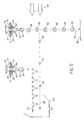
- FIG. 1 depicts in schematic block form an ink droplet forming assemblage to be included in a continuous inkjet printer
- FIG. 2 is depicts in cross-section an ink discharge nozzle, an ink heater, and a continuous ink filament projecting from the nozzle;
- FIGS. 3A depicts a multi-burst heater-activating pulse waveform for activating ink heaters at non-defective nozzles
- FIG. 3B depicts ink droplets resulting from the pulse waveform in FIG. 3A;
- FIG. 4A depicts a multi-burst heater-activating pulse waveform for activating ink heaters at a nozzle
- FIG. 4B depicts ink droplets resulting from the pulse waveform in FIG. 4A.
- FIG. 5 shows an air blower mechanism for separating ink droplets into printing and non-printing trajectories or paths.
- the invention is intended to be embodied in a continuous inkjet printer. Because the features of such a printer are generally known, the description which follows is directed in particular only to those elements forming part of or cooperating with the disclosed embodiment of the invention. It is to be understood, however, that other elements not disclosed may take various forms known to a person of ordinary skill in the art.
- FIG. 1 shows an ink droplet forming assemblage 10 that is to be included in a continuous inkjet printer such as the one disclosed in prior art U.S. Patent No. 6,079,821 issued June 27, 2000.
- the '821 patent is incorporated in this patent application.
- the ink droplet forming assemblage 10 shown in FIG. 1 generally comprises a printhead 12, at least one ink supply 14 and a controller 16. It is depicted in a schematic block form, which is not to scale for the sake of clarity.
- the controller 16 may, for example, be a known type logic control device or a suitably programmed microprocessor as in the incorporated '821 patent.
- ink discharge nozzles or outlets 18 are provided in a nozzle plate 19 on the printhead 12.
- Each one of the nozzles 18 is in continuous pressurized ink-receiving communication with the ink supply 14 via an ink passage 20, for example to provide black and white or single-color printing.
- the nozzles 18 may be in continuous pressurized ink-receiving communication with multiple continuous ink supplies, for example to provide multi-color printing using three or more ink colors such as yellow, cyan and magenta.
- a known pump, not shown, can serve as a continuous ink-pressurizing means.
- Respective known ink droplet generators i.e. filament stimulation sources, which preferably are ink heaters 22, are positioned on the printhead 12 around the ink discharge nozzles 18 as shown in FIG. 1.
- Each one of the ink heaters 22 is formed in a circular or ring shape and has a similar shape resistive heating element 24 electrically connected to a conductive contact pad 26 via a conductor 28. See FIGS. 1 and 2.
- the conductors 28 and contact pads 26 in FIG. 1 are at least partially formed or positioned on the printhead 12, and they provide an electrical connection between the controller 16 and the ink heaters 22.
- a pressurized ink 30 is formed into continuous inkjet filaments 32 (only one shown in FIG. 2) projecting from the ink discharge nozzles 18.
- the ink heaters 22 When heat-producing) as ink droplet generators, by causing respective filament end-lengths 34 to be broken off from the continuous inkjet filaments 32 at the nozzles 18 to provide discrete ink droplets (not shown in FIG. 2).
- the interval between successive droplet break-offs at any one nozzle 18 matches (corresponds to) the interval between successive activations of the ink heater 22 for that nozzle.
- the volume of the ink droplet when a droplet break-off occurs at the nozzle, corresponds to the frequency of activation of the ink heater for the nozzle.
- FIG. 3A shows an example of a multi-burst heater-activating pulse waveform 36 that can be provided by the controller 16 to one of the ink heaters 18 to activate the ink heater successive times to generate successive ink droplets.
- the pulse waveform 36 depicts a repeating series of heater-activating pulses 38, 40, 42 and 44. Each sequence of the four pulses 38, 40, 42 and 44 constitutes a single pulse burst.
- the intervals or delays 46 between the pulses 38 and 40, 40 and 42, and 44 and 38 are the same. Consequently, the ink droplets 48 resulting from the respective pulses 38, 40 and 42 have the same volume. See FIG. 3B.
- the interval or delay 50 between the pulses 42 and 44 is shorter than the intervals 46 between the pulses 38 and 40, 40 and 42, and 44 and 38. Consequently, the ink droplets 52 resulting from the pulses 44 have a similar volume that is less than the volume of the ink droplets 48.
- the ink droplets 46 that have the larger volume are intended to be used as printing ink droplets. Conversely, the ink droplets 52 that have the smaller volume are non-printing ink droplets.
- the printing or larger volume ink droplets 46 are intended to take a printing trajectory or path 54 from the nozzles 18 to a print medium 56 such as a paper sheet which may be supported on a known rotating drum (not shown).
- the non-printing or smaller volume ink droplets 52 are intended to take a non-printing trajectory or path 58 from the nozzles 18 to an ink gutter or catcher 60, in order to prevent the non-printing or smaller volume ink droplets 52 from reaching the print medium 56. Then, the non-printing or smaller volume ink droplets 52 are recycled back to the ink supply 14 via an appropriate conduit (not shown).
- a known air blower 62 blows air at a sufficient velocity to divert or deflect the non-printing or smaller volume ink droplets 52 into their non-printing trajectory 58 to the ink catcher 60.
- the air velocity is insufficient to remove the printing or larger volume ink droplets 46 from the printing trajectory 54.
- a problem that exists is that dirt or dried ink can accumulate on at least one of the nozzles 18, particularly in the region where the continuous inkjet filament 32 projects from the nozzle, and also possibly in the vicinity of the heating elements 24.
- the nozzle 18 must be considered defective because the ink droplets that result from the filament end-lengths 34 being broken off at the nozzle may be misdirected with respect to the printing trajectory 54 that the ink droplets should take. Consequently, the printed image may be of a lesser quality.
- respective annular detectors 64 line the nozzles 18, particularly in the region where the continuous inkjet filaments 32 project from the nozzles, and also in the vicinity of the heating elements 24, to detect any accumulation of dirt or dried ink at each nozzle, in order to determine whether a nozzle is defective.
- the detectors 64 can be positioned to detect any ink droplets that are misdirected with respect to the printing trajectory 54 because of the accumulation of dirt or dried ink, in order to determine whether a nozzle is defective.
- the detectors 64 are connected to the controller 16 to enable the controller to provide a multi-burst heater-activating pulse waveform 66 to the ink heater 22 of a defective one of the nozzles 18 to activate the ink heater successive times to generate successive ink droplets as shown in FIGS. 4A and 4B.
- the pulse waveform 66 in FIG. 4A depicts a repeating series of heater-activating pulses 68.
- a twelve-pulse sequence constitutes a single pulse burst.
- the intervals or delays 70 between the pulses 68 for the defective nozzle are the same, and they are shorter than the intervals 46 between the pulses 38 and 40, 40 and 42, and 44 and 38 and the interval 50 between the pulses 42 and 44 for the non-defective nozzles.
- the ink droplets 72 resulting from the pulses 68 have the smallest volume, i.e. they have a smaller volume than the ink droplets 48 resulting from the respective pulses 38, 40 and 42 (which in turn have a smaller volume than the ink droplets 52 resulting from the pulses 44). Compare FIGS. 3A and 3B with FIGS. 4A and 4B.
- the non-printing ink droplets 52 and 68 might have different volumes that are each larger than the volume of the printing ink droplets 48.
- the non-printing ink droplets 52 and 68 might have the same volume (but different than the volume of the printing ink droplets 48).
- the non-printing or smallest volume ink droplets 72 from a defective one of the nozzles 18 are intended to take a non-printing trajectory 74 to the ink gutter or catcher 60, in order to prevent the non-printing or smallest volume ink droplets from reaching the print medium 56. Then, the non-printing or smallest volume ink droplets 72 are recycled back to the ink supply 14 via the appropriate conduit (not shown).
- the non-printing trajectory 74 of the non-printing ink droplets 72 from a defective nozzle is substantially parallel to (and in the same direction as) the non-printing trajectory 58 of the non-printing ink droplets 52 from a non-defective nozzle.
- a known air blower 76 similar to the air blower 62, blows air at a higher velocity than the velocity of air blown by the latter blower to divert or deflect the non-printing or smallest volume ink droplets 72 into their non-printing trajectory 74 to the ink catcher 60.
- the higher air velocity is insufficient to remove the printing or larger volume ink droplets 46 from the printing trajectory 54.
- a vacuum source can be used to attract the non-printing ink droplets 72 and/or 52 to the respective trajectories.
- the two non-printing trajectories can be in opposite directions --- in which case a second ink gutter, in addition to the ink gutter 60, would be used.
- non-printing ink droplets 52 and 68 had the same volume (but different than the volume of the printing ink droplets 48), only a single air blower or vacuum source wold be sufficient since the non-printing ink droplets could be diverted to the same non-printing trajectory.
Landscapes
- Ink Jet (AREA)
- Particle Formation And Scattering Control In Inkjet Printers (AREA)
Abstract
Description
- The invention relates generally to continuous inkjet printing, and in particular to preventing a defective nozzle ink discharge in a continuous inkjet printhead from being used for printing.
- Typically in continuous inkjet printers, a pressurized ink is formed into continuous inkjet filaments projecting from multiple ink discharge nozzles in a printhead. Filament stimulation sources such as ink heaters or transducers operate as ink droplet generators each time they are activated, by causing filament end-lengths to be broken off at the respective nozzles to provide discrete ink droplets which, in turn, are deposited on a print medium moving relative to the printhead. The interval between successive droplet break-offs at any one nozzle matches the interval between successive activations of the filament stimulation source for that nozzle. The longer the interval between successive activations of the filament stimulation source for the nozzle, the longer the opportunity for the continuous inkjet filament to increase lengthwise at the nozzle and the larger the ink droplet. Conversely, the shorter the interval between successive activations of the filament stimulation source for the nozzle, the shorter the opportunity for the continuous inkjet filament to increase lengthwise at the nozzle and the smaller the ink droplet. Thus, the volume of the ink droplet, when a droplet break-off occurs at the nozzle, corresponds to the frequency of activation of the filament stimulation source for the nozzle.
- Successive ink droplets can be altered between printing and non-printing trajectories or paths. Those ink droplets that are in a printing trajectory are allowed to reach the print medium. Those ink droplets that are in a non-printing trajectory can be collected in a ink gutter or catcher and then recycled.
- A problem that exists is that dirt or dried ink can accumulate on a nozzle, particularly in the region where the continuous inkjet filament projects from the nozzle. When this occurs, the nozzle must be considered defective because the ink droplets that result from filament end-lengths being broken off at the nozzle may be misdirected with respect to the printing trajectory that the ink droplets should take. Consequently, the printed image may be of a lesser quality.
- The problem of misdirected ink droplets is particularly acute in continuous inkjet printers because ink flow to form a continuous inkjet filament at a nozzle that is defective cannot be stopped.
- According to one aspect of the invention, there is provided a method of preventing all of the ink discharged from a defective one of multiple nozzles in a continuous inkjet printhead from being used for printing on a print medium. Generally speaking, the method comprises:
- diverting all of the ink discharged from a defective nozzle from reaching a print medium, and allowing at least some of the ink discharged from other nozzles which are not defective to reach the print medium.
-
- More specifically, the method comprises:
- causing the defective nozzle to discharge only non-printing ink droplets, and allowing other nozzles which are not defective to discharge printing ink droplets which are volume-differentiated from non-printing droplets; and
- preventing non-printing droplets discharged from the defective nozzle from reaching a print medium, and allowing printing ink droplets discharged from the nozzles that are not defective to reach the print medium.
-
- Further specifically, the method comprises:
- periodically heating the defective nozzle at a frequency that is greater than frequencies other nozzles which are not defective are periodically heated, to cause the defective nozzle to only discharge ink droplets that have a smaller volume than ink droplets discharged from the nozzles that are not defective; and
- preventing smaller volume droplets discharged from the defective nozzle from reaching a print medium, and allowing larger volume ink droplets discharged from the nozzles that are not defective to reach the print medium.
-
- According to another aspect of the invention, there is provided apparatus for performing the foregoing method.
- FIG. 1 depicts in schematic block form an ink droplet forming assemblage to be included in a continuous inkjet printer;
- FIG. 2 is depicts in cross-section an ink discharge nozzle, an ink heater, and a continuous ink filament projecting from the nozzle;
- FIGS. 3A depicts a multi-burst heater-activating pulse waveform for activating ink heaters at non-defective nozzles;
- FIG. 3B depicts ink droplets resulting from the pulse waveform in FIG. 3A;
- FIG. 4A depicts a multi-burst heater-activating pulse waveform for activating ink heaters at a nozzle;
- FIG. 4B depicts ink droplets resulting from the pulse waveform in FIG. 4A; and
- FIG. 5 shows an air blower mechanism for separating ink droplets into printing and non-printing trajectories or paths.
- The invention is intended to be embodied in a continuous inkjet printer. Because the features of such a printer are generally known, the description which follows is directed in particular only to those elements forming part of or cooperating with the disclosed embodiment of the invention. It is to be understood, however, that other elements not disclosed may take various forms known to a person of ordinary skill in the art.
- FIG. 1 shows an ink
droplet forming assemblage 10 that is to be included in a continuous inkjet printer such as the one disclosed in prior art U.S. Patent No. 6,079,821 issued June 27, 2000. The '821 patent is incorporated in this patent application. - Coincident with a description of the ink
droplet forming mechanism 10 which follows, there is provided a method of preventing all of the ink discharged from a defective one of multiple nozzles in the mechanism from being used for printing on a print medium. - The ink
droplet forming assemblage 10 shown in FIG. 1 generally comprises aprinthead 12, at least oneink supply 14 and acontroller 16. It is depicted in a schematic block form, which is not to scale for the sake of clarity. Thecontroller 16 may, for example, be a known type logic control device or a suitably programmed microprocessor as in the incorporated '821 patent. - Multiple ink discharge nozzles or outlets 18 (only five shown in FIG. 1) are provided in a
nozzle plate 19 on theprinthead 12. Each one of thenozzles 18 is in continuous pressurized ink-receiving communication with theink supply 14 via anink passage 20, for example to provide black and white or single-color printing. Alternatively, thenozzles 18 may be in continuous pressurized ink-receiving communication with multiple continuous ink supplies, for example to provide multi-color printing using three or more ink colors such as yellow, cyan and magenta. A known pump, not shown, can serve as a continuous ink-pressurizing means. - Respective known ink droplet generators, i.e. filament stimulation sources, which preferably are
ink heaters 22, are positioned on theprinthead 12 around theink discharge nozzles 18 as shown in FIG. 1. Each one of theink heaters 22 is formed in a circular or ring shape and has a similar shaperesistive heating element 24 electrically connected to aconductive contact pad 26 via aconductor 28. See FIGS. 1 and 2. Theconductors 28 andcontact pads 26 in FIG. 1 are at least partially formed or positioned on theprinthead 12, and they provide an electrical connection between thecontroller 16 and theink heaters 22. - Typically, as shown in FIG. 2, a
pressurized ink 30 is formed into continuous inkjet filaments 32 (only one shown in FIG. 2) projecting from theink discharge nozzles 18. Each time theink heaters 22 are activated they operate (when heat-producing) as ink droplet generators, by causing respective filament end-lengths 34 to be broken off from thecontinuous inkjet filaments 32 at thenozzles 18 to provide discrete ink droplets (not shown in FIG. 2). The interval between successive droplet break-offs at any onenozzle 18 matches (corresponds to) the interval between successive activations of theink heater 22 for that nozzle. The longer the interval between successive activations of theink heater 22 for thenozzle 18, the longer the opportunity for thecontinuous inkjet filament 32 to increase lengthwise at the nozzle and the larger the ink droplet. Conversely, the shorter the interval between successive activations of the ink heater for the nozzle, the shorter the opportunity for the continuous inkjet filament to increase lengthwise at the nozzle and the smaller the ink droplet. Thus, the volume of the ink droplet, when a droplet break-off occurs at the nozzle, corresponds to the frequency of activation of the ink heater for the nozzle. - FIG. 3A shows an example of a multi-burst heater-activating
pulse waveform 36 that can be provided by thecontroller 16 to one of theink heaters 18 to activate the ink heater successive times to generate successive ink droplets. Thepulse waveform 36 depicts a repeating series of heater-activatingpulses pulses delays 46 between thepulses ink droplets 48 resulting from therespective pulses pulses intervals 46 between thepulses ink droplets 52 resulting from thepulses 44 have a similar volume that is less than the volume of theink droplets 48. - The
ink droplets 46 that have the larger volume are intended to be used as printing ink droplets. Conversely, theink droplets 52 that have the smaller volume are non-printing ink droplets. - As shown in FIG. 5, the printing or larger
volume ink droplets 46 are intended to take a printing trajectory orpath 54 from thenozzles 18 to aprint medium 56 such as a paper sheet which may be supported on a known rotating drum (not shown). Conversely, the non-printing or smallervolume ink droplets 52 are intended to take a non-printing trajectory orpath 58 from thenozzles 18 to an ink gutter orcatcher 60, in order to prevent the non-printing or smallervolume ink droplets 52 from reaching theprint medium 56. Then, the non-printing or smallervolume ink droplets 52 are recycled back to theink supply 14 via an appropriate conduit (not shown). A knownair blower 62 blows air at a sufficient velocity to divert or deflect the non-printing or smallervolume ink droplets 52 into theirnon-printing trajectory 58 to theink catcher 60. The air velocity is insufficient to remove the printing or largervolume ink droplets 46 from theprinting trajectory 54. - A problem that exists is that dirt or dried ink can accumulate on at least one of the
nozzles 18, particularly in the region where thecontinuous inkjet filament 32 projects from the nozzle, and also possibly in the vicinity of theheating elements 24. When this occurs, thenozzle 18 must be considered defective because the ink droplets that result from the filament end-lengths 34 being broken off at the nozzle may be misdirected with respect to theprinting trajectory 54 that the ink droplets should take. Consequently, the printed image may be of a lesser quality. - The solution to the problem is as follows. As shown in FIGS. 1 and 2, respective
annular detectors 64 line thenozzles 18, particularly in the region where thecontinuous inkjet filaments 32 project from the nozzles, and also in the vicinity of theheating elements 24, to detect any accumulation of dirt or dried ink at each nozzle, in order to determine whether a nozzle is defective. Alternatively, thedetectors 64 can be positioned to detect any ink droplets that are misdirected with respect to theprinting trajectory 54 because of the accumulation of dirt or dried ink, in order to determine whether a nozzle is defective. Thedetectors 64 are connected to thecontroller 16 to enable the controller to provide a multi-burst heater-activatingpulse waveform 66 to theink heater 22 of a defective one of thenozzles 18 to activate the ink heater successive times to generate successive ink droplets as shown in FIGS. 4A and 4B. Thepulse waveform 66 in FIG. 4A depicts a repeating series of heater-activatingpulses 68. A twelve-pulse sequence constitutes a single pulse burst. The intervals ordelays 70 between thepulses 68 for the defective nozzle are the same, and they are shorter than theintervals 46 between thepulses interval 50 between thepulses ink droplets 72 resulting from thepulses 68 have the smallest volume, i.e. they have a smaller volume than theink droplets 48 resulting from therespective pulses ink droplets 52 resulting from the pulses 44). Compare FIGS. 3A and 3B with FIGS. 4A and 4B. - Like the
non-printing ink droplets 52 from a non-defective one of thenozzles 18, the smallestvolume ink droplets 72 from a defective nozzle are non-printing ink droplets. Of course, this methodology can be reversed or modified. That is to say, thenon-printing ink droplets printing ink droplets 48. Alternatively, thenon-printing ink droplets - As shown in FIG. 5, the non-printing or smallest
volume ink droplets 72 from a defective one of thenozzles 18 are intended to take anon-printing trajectory 74 to the ink gutter orcatcher 60, in order to prevent the non-printing or smallest volume ink droplets from reaching theprint medium 56. Then, the non-printing or smallestvolume ink droplets 72 are recycled back to theink supply 14 via the appropriate conduit (not shown). Thenon-printing trajectory 74 of thenon-printing ink droplets 72 from a defective nozzle is substantially parallel to (and in the same direction as) thenon-printing trajectory 58 of thenon-printing ink droplets 52 from a non-defective nozzle. A known air blower 76, similar to theair blower 62, blows air at a higher velocity than the velocity of air blown by the latter blower to divert or deflect the non-printing or smallestvolume ink droplets 72 into theirnon-printing trajectory 74 to theink catcher 60. The higher air velocity is insufficient to remove the printing or largervolume ink droplets 46 from theprinting trajectory 54. - Instead of one or both of the
air blowers 76 and 62 which divert thenon-printing ink droplets non-defective nozzles 18 to thenon-printing trajectories non-printing ink droplets 72 and/or 52 to the respective trajectories. Moreover, instead of thenon-printing trajectory 74 being in the same direction as thenon-printing trajectory 58, the two non-printing trajectories can be in opposite directions --- in which case a second ink gutter, in addition to theink gutter 60, would be used. - If the
non-printing ink droplets
Claims (11)
- A method of preventing all of the ink discharged from a defective one of multiple nozzles in a continuous inkjet printhead from being used for printing on a print medium, said method comprising:diverting all of the ink discharged from a defective nozzle from reaching a print medium, and allowing at least some of the ink discharged from other nozzles which are not defective to reach the print medium.
- A method as recited in claim 1, further comprising:collecting all of the ink discharged from the defective nozzle to be recycled for later discharge from the nozzles that are not defective.
- A method as recited in claim 2, wherein some of the ink discharged from the nozzles that are not defective is diverted from reaching the print medium and is collected with all of the ink discharged from the defective nozzle to be recycled.
- A method as recited in claim 3, wherein all of the ink discharged from the defective nozzle, and the ink discharged from the nozzles that are not defective which is prevented from reaching the print medium, are formed as discrete ink droplets each having a smaller volume than discrete ink droplets formed from the ink discharged from the nozzles that are not defective which is allowed to reach the print medium.
- A method as recited in claim 4, wherein the smaller volume droplets from the defective nozzle may have the same or less volume than the smaller volume droplets from the nozzles that are not defective.
- Apparatus for preventing all of the ink discharged from a defective one of multiple nozzles in a continuous inkjet printhead from being used for printing on a print medium, said apparatus comprising:means for diverting all of the ink discharged from a defective nozzle from reaching a print medium; and means for causing at least some of the ink discharged from other nozzles which are not defective to reach the print medium.
- Apparatus as recited in claim 6, wherein
said causing means includes respective activatable filament stimulation sources for continuous ink filaments at nozzles that are not defective, which are activated at a particular frequency to break off discrete ink droplets from the ink filaments at a corresponding rate, and
said diverting means includes an activatable filament stimulation source for a continuous ink filament at a defective nozzle, which is activated at a frequency that is higher than for said filament stimulation sources for continuous ink filaments at nozzles that are not defective, to break off discrete ink droplets from a continuous ink filament at a defective nozzle at a rate faster than for breaking off discrete ink droplets from continuous ink filaments at nozzles that are not defective, in order that ink droplets from a continuous ink filament at a defective nozzle have a smaller volume than ink droplets from continuous ink filaments at nozzles that are not defective. - A method of preventing all of the ink discharged from a defective one of multiple nozzles in a continuous inkjet printhead from being used for printing on a print medium, said method comprising:causing the defective nozzle to discharge only non-printing ink droplets, and allowing other nozzles which are not defective to discharge printing ink droplets; andpreventing non-printing droplets discharged from the defective nozzle from reaching a print medium, and allowing printing ink droplets discharged from the nozzles that are not defective to reach the print medium.
- Apparatus for preventing all of the ink discharged from a defective one of multiple nozzles in a continuous inkjet printhead, from being used for printing on a print medium, said apparatus comprising:means for periodically heating a defective nozzle at a frequency that is greater than frequencies other nozzles which are not defective are periodically heated, to cause a defective nozzle to only discharge ink droplets that have a smaller volume than ink droplets discharged from nozzles that are not defective; andmeans for preventing smaller volume droplets discharged from a defective nozzle from reaching a print medium, and allowing larger volume ink droplets discharged from nozzles that are not defective to reach the print medium.
- Apparatus for preventing all of the ink discharged from a defective one of multiple nozzles in a continuous inkjet printhead, from being used for printing on a print medium, said apparatus comprising:an ink droplet generator that stimulates an ink filament projecting from a defective nozzle, to cause a defective nozzle to only discharge ink droplets that have a smaller volume than ink droplets that can be discharged from nozzles that are not defective.
- Apparatus as recited in claim 10, further comprising:an ink droplet diverter that prevents smaller volume droplets discharged from a defective nozzle from reaching a print medium, but allows larger volume ink droplets discharged from nozzles that are not defective to reach the print medium.
Applications Claiming Priority (2)
| Application Number | Priority Date | Filing Date | Title |
|---|---|---|---|
| US375514 | 2003-02-25 | ||
| US10/375,514 US7004571B2 (en) | 2003-02-25 | 2003-02-25 | Preventing defective nozzle ink discharge in continuous inkjet printhead from being used for printing |
Publications (1)
| Publication Number | Publication Date |
|---|---|
| EP1452314A1 true EP1452314A1 (en) | 2004-09-01 |
Family
ID=32771462
Family Applications (1)
| Application Number | Title | Priority Date | Filing Date |
|---|---|---|---|
| EP04075457A Withdrawn EP1452314A1 (en) | 2003-02-25 | 2004-02-13 | Preventing defective nozzle ink discharge in continuous inkjet printhead from being used for printing |
Country Status (3)
| Country | Link |
|---|---|
| US (1) | US7004571B2 (en) |
| EP (1) | EP1452314A1 (en) |
| JP (1) | JP4361815B2 (en) |
Cited By (1)
| Publication number | Priority date | Publication date | Assignee | Title |
|---|---|---|---|---|
| WO2006060621A3 (en) * | 2004-12-03 | 2006-09-28 | Eastman Kodak Co | Methods and apparatuses for forming an article |
Families Citing this family (3)
| Publication number | Priority date | Publication date | Assignee | Title |
|---|---|---|---|---|
| US8919930B2 (en) * | 2010-04-27 | 2014-12-30 | Eastman Kodak Company | Stimulator/filter device that spans printhead liquid chamber |
| JP2012236299A (en) * | 2011-05-11 | 2012-12-06 | Seiko Epson Corp | Fluid discharge device, nozzle inspection method, and nozzle inspection program |
| WO2014116209A1 (en) | 2013-01-23 | 2014-07-31 | Hewlett-Packard Development Company, L.P. | Testing a printhead |
Citations (6)
| Publication number | Priority date | Publication date | Assignee | Title |
|---|---|---|---|---|
| EP0255560A1 (en) * | 1986-08-06 | 1988-02-10 | Océ-Nederland B.V. | Multi-nozzle ink jet printer |
| US4999644A (en) * | 1989-12-18 | 1991-03-12 | Eastman Kodak Company | User selectable drop charge synchronization for traveling wave-stimulated, continuous ink jet printers |
| US6079821A (en) | 1997-10-17 | 2000-06-27 | Eastman Kodak Company | Continuous ink jet printer with asymmetric heating drop deflection |
| EP1219430A1 (en) * | 2000-12-28 | 2002-07-03 | Eastman Kodak Company | Printhead having gas flow ink droplet separation and method of diverging ink droplets |
| EP1243426A2 (en) * | 2001-03-13 | 2002-09-25 | Eastman Kodak Company | A continuous ink-jet printhead for modifying ink drop placement |
| US6491362B1 (en) * | 2001-07-20 | 2002-12-10 | Eastman Kodak Company | Continuous ink jet printing apparatus with improved drop placement |
Family Cites Families (15)
| Publication number | Priority date | Publication date | Assignee | Title |
|---|---|---|---|---|
| US3596275A (en) | 1964-03-25 | 1971-07-27 | Richard G Sweet | Fluid droplet recorder |
| US3562757A (en) | 1968-02-28 | 1971-02-09 | Dick Co Ab | Guard drop technique for ink jet systems |
| US3709432A (en) * | 1971-05-19 | 1973-01-09 | Mead Corp | Method and apparatus for aerodynamic switching |
| US4097872A (en) | 1976-12-20 | 1978-06-27 | International Business Machines Corporation | Axial droplet aspirator |
| JPS55158974A (en) * | 1979-05-26 | 1980-12-10 | Ricoh Co Ltd | Choking detector in ink jet printer and remover thereof |
| US4297712A (en) | 1979-09-17 | 1981-10-27 | International Business Machines Corporation | Air flow tunnel for reducing ink jet drag on array head |
| JPS56129181A (en) | 1980-03-17 | 1981-10-09 | Ricoh Co Ltd | Corrector for deviation of dot in ink jet printer |
| JPS61114856A (en) * | 1984-11-09 | 1986-06-02 | Hitachi Ltd | Ink jet recorder |
| US6081281A (en) | 1991-12-30 | 2000-06-27 | Vutek, Inc. | Spray head for a computer-controlled automatic image reproduction system |
| AU6622296A (en) | 1995-08-04 | 1997-03-05 | Domino Printing Sciences Plc | Continuous ink-jet printer and method of operation |
| US6003980A (en) | 1997-03-28 | 1999-12-21 | Jemtex Ink Jet Printing Ltd. | Continuous ink jet printing apparatus and method including self-testing for printing errors |
| US6217163B1 (en) * | 1998-12-28 | 2001-04-17 | Eastman Kodak Company | Continuous ink jet print head having multi-segment heaters |
| US6352330B1 (en) | 2000-03-01 | 2002-03-05 | Eastman Kodak Company | Ink jet plate maker and proofer apparatus and method |
| JP4631164B2 (en) * | 2000-12-25 | 2011-02-16 | リコープリンティングシステムズ株式会社 | Ink jet recording apparatus and control method thereof |
| US6588888B2 (en) | 2000-12-28 | 2003-07-08 | Eastman Kodak Company | Continuous ink-jet printing method and apparatus |
-
2003
- 2003-02-25 US US10/375,514 patent/US7004571B2/en not_active Expired - Fee Related
-
2004
- 2004-02-12 JP JP2004034932A patent/JP4361815B2/en not_active Expired - Fee Related
- 2004-02-13 EP EP04075457A patent/EP1452314A1/en not_active Withdrawn
Patent Citations (6)
| Publication number | Priority date | Publication date | Assignee | Title |
|---|---|---|---|---|
| EP0255560A1 (en) * | 1986-08-06 | 1988-02-10 | Océ-Nederland B.V. | Multi-nozzle ink jet printer |
| US4999644A (en) * | 1989-12-18 | 1991-03-12 | Eastman Kodak Company | User selectable drop charge synchronization for traveling wave-stimulated, continuous ink jet printers |
| US6079821A (en) | 1997-10-17 | 2000-06-27 | Eastman Kodak Company | Continuous ink jet printer with asymmetric heating drop deflection |
| EP1219430A1 (en) * | 2000-12-28 | 2002-07-03 | Eastman Kodak Company | Printhead having gas flow ink droplet separation and method of diverging ink droplets |
| EP1243426A2 (en) * | 2001-03-13 | 2002-09-25 | Eastman Kodak Company | A continuous ink-jet printhead for modifying ink drop placement |
| US6491362B1 (en) * | 2001-07-20 | 2002-12-10 | Eastman Kodak Company | Continuous ink jet printing apparatus with improved drop placement |
Cited By (3)
| Publication number | Priority date | Publication date | Assignee | Title |
|---|---|---|---|---|
| WO2006060621A3 (en) * | 2004-12-03 | 2006-09-28 | Eastman Kodak Co | Methods and apparatuses for forming an article |
| US7288469B2 (en) | 2004-12-03 | 2007-10-30 | Eastman Kodak Company | Methods and apparatuses for forming an article |
| US7669988B2 (en) | 2004-12-03 | 2010-03-02 | Eastman Kodak Company | Methods and apparatuses for forming an article |
Also Published As
| Publication number | Publication date |
|---|---|
| JP2004255872A (en) | 2004-09-16 |
| US7004571B2 (en) | 2006-02-28 |
| JP4361815B2 (en) | 2009-11-11 |
| US20040165038A1 (en) | 2004-08-26 |
Similar Documents
| Publication | Publication Date | Title |
|---|---|---|
| JP4847562B2 (en) | Image printing apparatus and method for separating ink droplets | |
| US6793328B2 (en) | Continuous ink jet printing apparatus with improved drop placement | |
| US6491362B1 (en) | Continuous ink jet printing apparatus with improved drop placement | |
| EP0911168B1 (en) | Continuous ink jet printer with asymmetric heating drop deflection | |
| EP1016527B1 (en) | Continuous ink jet print head having multi-segment heaters | |
| EP1277579B1 (en) | A continuous ink jet printing apparatus with nozzles having different diameters | |
| EP1219431B1 (en) | A drop-masking continuous inkjet printing method and apparatus | |
| JP2010527300A (en) | Continuous printer with improved actuator drive waveform | |
| US6474781B1 (en) | Continuous ink-jet printing method and apparatus with nozzle clusters | |
| US6517190B2 (en) | Ink jet printing method and ink jet printer | |
| JP2014515324A (en) | Liquid discharge system with droplet velocity modulation | |
| EP1366900A2 (en) | Printer with means to prevent overheating | |
| US6923529B2 (en) | Ink-jet printing with reduced cross-talk | |
| EP1332877B1 (en) | Continuous ink jet printing method and apparatus | |
| US7004571B2 (en) | Preventing defective nozzle ink discharge in continuous inkjet printhead from being used for printing | |
| JP2000127443A5 (en) | ||
| KR20140017436A (en) | System and method for clearing weak and missing inkjets in an inkjet printer | |
| EP0873869A2 (en) | Printhead and driver for jetting heaters and substrate heater in an ink jet printer and method of controlling such heaters | |
| US7255427B2 (en) | Liquid ejection device and image forming apparatus | |
| US6644792B1 (en) | Ink droplet forming apparatus and method for use in ink jet printer system | |
| JP4507344B2 (en) | Line printer | |
| JP2008100526A (en) | Image forming method and apparatus | |
| JP4022691B2 (en) | Image forming apparatus | |
| JP2006095772A (en) | Image forming apparatus |
Legal Events
| Date | Code | Title | Description |
|---|---|---|---|
| PUAI | Public reference made under article 153(3) epc to a published international application that has entered the european phase |
Free format text: ORIGINAL CODE: 0009012 |
|
| AK | Designated contracting states |
Kind code of ref document: A1 Designated state(s): AT BE BG CH CY CZ DE DK EE ES FI FR GB GR HU IE IT LI LU MC NL PT RO SE SI SK TR |
|
| AX | Request for extension of the european patent |
Extension state: AL LT LV MK |
|
| 17P | Request for examination filed |
Effective date: 20050119 |
|
| AKX | Designation fees paid |
Designated state(s): DE FR GB |
|
| RBV | Designated contracting states (corrected) |
Designated state(s): DE FR GB |
|
| 17Q | First examination report despatched |
Effective date: 20091020 |
|
| GRAC | Information related to communication of intention to grant a patent modified |
Free format text: ORIGINAL CODE: EPIDOSCIGR1 |
|
| GRAP | Despatch of communication of intention to grant a patent |
Free format text: ORIGINAL CODE: EPIDOSNIGR1 |
|
| GRAJ | Information related to disapproval of communication of intention to grant by the applicant or resumption of examination proceedings by the epo deleted |
Free format text: ORIGINAL CODE: EPIDOSDIGR1 |
|
| GRAP | Despatch of communication of intention to grant a patent |
Free format text: ORIGINAL CODE: EPIDOSNIGR1 |
|
| GRAC | Information related to communication of intention to grant a patent modified |
Free format text: ORIGINAL CODE: EPIDOSCIGR1 |
|
| STAA | Information on the status of an ep patent application or granted ep patent |
Free format text: STATUS: THE APPLICATION IS DEEMED TO BE WITHDRAWN |
|
| 18D | Application deemed to be withdrawn |
Effective date: 20130226 |