JP5426536B2 - Continuous printer with improved actuator drive waveform - Google Patents
Continuous printer with improved actuator drive waveform Download PDFInfo
- Publication number
- JP5426536B2 JP5426536B2 JP2010508379A JP2010508379A JP5426536B2 JP 5426536 B2 JP5426536 B2 JP 5426536B2 JP 2010508379 A JP2010508379 A JP 2010508379A JP 2010508379 A JP2010508379 A JP 2010508379A JP 5426536 B2 JP5426536 B2 JP 5426536B2
- Authority
- JP
- Japan
- Prior art keywords
- droplet
- ink
- droplets
- large volume
- small volume
- Prior art date
- Legal status (The legal status is an assumption and is not a legal conclusion. Google has not performed a legal analysis and makes no representation as to the accuracy of the status listed.)
- Active
Links
- 238000000034 method Methods 0.000 claims description 26
- 239000007788 liquid Substances 0.000 claims description 15
- 230000005284 excitation Effects 0.000 claims description 5
- 239000012634 fragment Substances 0.000 claims description 4
- 241000080590 Niso Species 0.000 claims 1
- 230000000737 periodic effect Effects 0.000 claims 1
- 238000007639 printing Methods 0.000 description 33
- 239000012530 fluid Substances 0.000 description 30
- 238000004519 manufacturing process Methods 0.000 description 9
- 239000000463 material Substances 0.000 description 6
- 238000011084 recovery Methods 0.000 description 6
- 238000004581 coalescence Methods 0.000 description 5
- 239000003086 colorant Substances 0.000 description 5
- 230000000694 effects Effects 0.000 description 5
- 238000007641 inkjet printing Methods 0.000 description 5
- 230000005856 abnormality Effects 0.000 description 4
- 238000005516 engineering process Methods 0.000 description 4
- 230000015572 biosynthetic process Effects 0.000 description 3
- 239000004020 conductor Substances 0.000 description 2
- 238000007796 conventional method Methods 0.000 description 2
- 238000010586 diagram Methods 0.000 description 2
- 239000000203 mixture Substances 0.000 description 2
- 239000004065 semiconductor Substances 0.000 description 2
- 230000007704 transition Effects 0.000 description 2
- 238000011144 upstream manufacturing Methods 0.000 description 2
- 238000012937 correction Methods 0.000 description 1
- 230000007423 decrease Effects 0.000 description 1
- 238000007599 discharging Methods 0.000 description 1
- 239000000428 dust Substances 0.000 description 1
- 230000007613 environmental effect Effects 0.000 description 1
- 239000004744 fabric Substances 0.000 description 1
- 239000000835 fiber Substances 0.000 description 1
- 239000002657 fibrous material Substances 0.000 description 1
- 238000005187 foaming Methods 0.000 description 1
- 238000010438 heat treatment Methods 0.000 description 1
- 238000005259 measurement Methods 0.000 description 1
- 230000005499 meniscus Effects 0.000 description 1
- 238000012545 processing Methods 0.000 description 1
- 238000010992 reflux Methods 0.000 description 1
- 238000000926 separation method Methods 0.000 description 1
- 229910052710 silicon Inorganic materials 0.000 description 1
- 239000010703 silicon Substances 0.000 description 1
- 229910001220 stainless steel Inorganic materials 0.000 description 1
- 239000010935 stainless steel Substances 0.000 description 1
- 239000000758 substrate Substances 0.000 description 1
- 230000009897 systematic effect Effects 0.000 description 1
- 238000012546 transfer Methods 0.000 description 1
- 125000000391 vinyl group Chemical group [H]C([*])=C([H])[H] 0.000 description 1
- 229920002554 vinyl polymer Polymers 0.000 description 1
Images


Classifications
-
- B—PERFORMING OPERATIONS; TRANSPORTING
- B41—PRINTING; LINING MACHINES; TYPEWRITERS; STAMPS
- B41J—TYPEWRITERS; SELECTIVE PRINTING MECHANISMS, i.e. MECHANISMS PRINTING OTHERWISE THAN FROM A FORME; CORRECTION OF TYPOGRAPHICAL ERRORS
- B41J2/00—Typewriters or selective printing mechanisms characterised by the printing or marking process for which they are designed
- B41J2/005—Typewriters or selective printing mechanisms characterised by the printing or marking process for which they are designed characterised by bringing liquid or particles selectively into contact with a printing material
- B41J2/01—Ink jet
- B41J2/015—Ink jet characterised by the jet generation process
- B41J2/02—Ink jet characterised by the jet generation process generating a continuous ink jet
- B41J2/03—Ink jet characterised by the jet generation process generating a continuous ink jet by pressure
-
- B—PERFORMING OPERATIONS; TRANSPORTING
- B41—PRINTING; LINING MACHINES; TYPEWRITERS; STAMPS
- B41J—TYPEWRITERS; SELECTIVE PRINTING MECHANISMS, i.e. MECHANISMS PRINTING OTHERWISE THAN FROM A FORME; CORRECTION OF TYPOGRAPHICAL ERRORS
- B41J2/00—Typewriters or selective printing mechanisms characterised by the printing or marking process for which they are designed
- B41J2/005—Typewriters or selective printing mechanisms characterised by the printing or marking process for which they are designed characterised by bringing liquid or particles selectively into contact with a printing material
- B41J2/01—Ink jet
- B41J2/015—Ink jet characterised by the jet generation process
- B41J2/02—Ink jet characterised by the jet generation process generating a continuous ink jet
- B41J2002/022—Control methods or devices for continuous ink jet
-
- B—PERFORMING OPERATIONS; TRANSPORTING
- B41—PRINTING; LINING MACHINES; TYPEWRITERS; STAMPS
- B41J—TYPEWRITERS; SELECTIVE PRINTING MECHANISMS, i.e. MECHANISMS PRINTING OTHERWISE THAN FROM A FORME; CORRECTION OF TYPOGRAPHICAL ERRORS
- B41J2/00—Typewriters or selective printing mechanisms characterised by the printing or marking process for which they are designed
- B41J2/005—Typewriters or selective printing mechanisms characterised by the printing or marking process for which they are designed characterised by bringing liquid or particles selectively into contact with a printing material
- B41J2/01—Ink jet
- B41J2/015—Ink jet characterised by the jet generation process
- B41J2/02—Ink jet characterised by the jet generation process generating a continuous ink jet
- B41J2/03—Ink jet characterised by the jet generation process generating a continuous ink jet by pressure
- B41J2002/031—Gas flow deflection
-
- B—PERFORMING OPERATIONS; TRANSPORTING
- B41—PRINTING; LINING MACHINES; TYPEWRITERS; STAMPS
- B41J—TYPEWRITERS; SELECTIVE PRINTING MECHANISMS, i.e. MECHANISMS PRINTING OTHERWISE THAN FROM A FORME; CORRECTION OF TYPOGRAPHICAL ERRORS
- B41J2/00—Typewriters or selective printing mechanisms characterised by the printing or marking process for which they are designed
- B41J2/005—Typewriters or selective printing mechanisms characterised by the printing or marking process for which they are designed characterised by bringing liquid or particles selectively into contact with a printing material
- B41J2/01—Ink jet
- B41J2/015—Ink jet characterised by the jet generation process
- B41J2/02—Ink jet characterised by the jet generation process generating a continuous ink jet
- B41J2/03—Ink jet characterised by the jet generation process generating a continuous ink jet by pressure
- B41J2002/033—Continuous stream with droplets of different sizes
Description
本発明はディジタル制御印刷機、特に液体インク流を液滴へと破断させそれらを適宜偏向させる連続式インクジェットプリンタに関する。 The present invention relates to digitally controlled printing machines, and more particularly to continuous ink jet printers that break liquid ink streams into droplets and deflect them accordingly.
ディジタル制御カラー印刷方式としては従来から二種類の方式が採用されている。どちらの方式でも、印刷に使用するインクの色毎にインク源を設け、そのインクをプリントヘッド上のチャネル経由でノズルに送り、それらのノズルのうち必要なものからインクの液滴(インク滴)を吐出させて印刷媒体に付着させる、という仕組みを採っている。また、どちらの方式でも印刷用インク色毎にインク供給系を分けるのが普通である。その印刷用インクの色は、通常はシアン、イエロー及びマゼンタの三基本色である。この三色を使用するのは、合計で数百万色もの色彩乃至中間色をそれらの減法混色で発現させうるからである。 Conventionally, two types of digitally controlled color printing methods have been adopted. In both methods, an ink source is provided for each color of ink used for printing, the ink is sent to a nozzle via a channel on the print head, and ink droplets (ink droplets) from those required among those nozzles. The mechanism of discharging the ink and attaching it to the print medium is adopted. In either method, the ink supply system is usually divided for each printing ink color. The colors of the printing ink are usually three basic colors of cyan, yellow and magenta. These three colors are used because a total of several million colors or intermediate colors can be expressed by their subtractive color mixture.
従来方式のうち第1のものはドロップオンデマンドインクジェット印刷方式と通称されている。この方式では、熱、圧電等による加圧用のアクチュエータを使用し、必要なインク滴のみを発生させ印刷媒体の記録面上に射突させる。必要なインク滴はアクチュエータのうち対応するもののみを駆動することで生成、吐出させることができる。そのインク滴はプリントヘッド・印刷媒体間空間を飛翔し印刷媒体に射突する。従って、インク滴生成動作を制御し画像発現に必要なインク滴のみを選別的に生成することで、印刷したい画像を発現させることができる。各チャネル内の圧力は、不要なインクが出てノズルが汚れることを防ぐため、ノズルにおけるインク面が微かに凹状メニスカスを呈するよう若干負圧にするのが普通である。 The first of the conventional methods is commonly called a drop-on-demand ink jet printing method. In this method, an actuator for pressurization by heat, piezoelectric or the like is used, and only necessary ink droplets are generated and projected onto the recording surface of the print medium. Necessary ink droplets can be generated and ejected by driving only the corresponding one of the actuators. The ink droplets fly through the space between the print head and the print medium and hit the print medium. Therefore, by controlling the ink droplet generation operation and selectively generating only ink droplets necessary for the image expression, it is possible to develop the image to be printed. In order to prevent unnecessary ink from coming out and causing the nozzle to become dirty, the pressure in each channel is usually slightly negative so that the ink surface at the nozzle has a slightly concave meniscus.
例えば既存のドロップオンデマンドインクジェットプリンタでは、そのプリントヘッドのオリフィス(ノズル開口)でインク滴を発生させるのに熱アクチュエータか圧電アクチュエータが使用されている。熱アクチュエータは、相応の場所に配置しておいたヒータでその周辺にある幾ばくかのインクを加熱して相変化させ、それにより発生するインク気泡でチャネル内圧を十分に高めてインク滴を吐出させるアクチュエータである。他方の圧電アクチュエータは機械力の印加でインク滴を吐出させるアクチュエータである。 For example, in existing drop-on-demand ink jet printers, a thermal actuator or a piezoelectric actuator is used to generate ink droplets at the orifice (nozzle opening) of the print head. The thermal actuator heats some of the ink around it with a heater placed in the appropriate place to change the phase, and the ink bubbles generated thereby sufficiently increase the internal pressure of the channel to eject ink droplets. Actuator. The other piezoelectric actuator is an actuator that ejects ink droplets by applying mechanical force.
第2の従来方式は連続流式又は単に連続式インクジェット印刷方式と通称されている。古くは、複数個のインク滴が陸続と続くインク滴流を加圧インク源で発生させ、そのインク滴のうち必要なものを帯電させ、帯電させたインク滴を偏向電極で偏向させる仕組みが採られていた。偏向を受けた帯電インク滴は非帯電インク滴と異なる経路で飛翔していくので、それら帯電インク滴及び非帯電インク滴のうち一方で印刷媒体上への印刷を行うことができる。他方のインク滴は、キャッチャ、インタセプタ、ガター等と呼ばれるインク捕獲機構に導き再循環や廃棄に回せばよい。例えば特許文献1(発明者:Hansell、発行日:1933年12月26日)及び特許文献2(発明者:Sweet et al.、発行日:1968年3月12日)に記載の連続式インクジェット印刷用ノズルアレイでは、インク滴のうち印刷に使用したいものを選んで帯電させ、印刷媒体に達するようそのインク滴を偏向させている。 The second conventional method is commonly called a continuous flow method or simply a continuous ink jet printing method. In the old days, there is a mechanism in which a plurality of ink droplets are continuously generated by a pressurized ink source, a necessary one of the ink droplets is charged, and the charged ink droplet is deflected by a deflection electrode. It was taken. Since the charged ink droplets subjected to the deflection fly along a path different from that of the non-charged ink droplets, one of the charged ink droplets and the non-charged ink droplets can be printed on the print medium. The other ink droplet may be led to an ink capture mechanism called a catcher, interceptor, gutter, etc., and recycled or discarded. For example, continuous ink jet printing described in Patent Document 1 (inventor: Hansell, issue date: December 26, 1933) and Patent Document 2 (inventor: Sweet et al., Issue date: March 12, 1968) In the nozzle array, the ink droplets to be used for printing are selected and charged, and the ink droplets are deflected so as to reach the printing medium.
特許文献3(発明者:Robertson、発行日:1973年1月9日)に記載の方法及び装置では、作用流体フィラメントを生成してそれを破断させ複数個のインク滴を均等間隔に生成する動作を、何個かのトランスデューサを使用し実行する。その際、破断してインク滴になる前のフィラメントの長さを、トランスデューサに供給される励起エネルギを制御して調節する。例えば大振幅励起なら短尺フィラメントになり、小振幅励起なら長尺フィラメントになる。生成された長尺,短尺各フィラメントは、空気流を過ぎりつつ作用流体経路沿いに飛翔していく。その空気流は長尺,短尺各フィラメントの先端から後端にかけて諸点で作用するので、それら未破断でインク滴になっていないフィラメントに対しその空気流が及ぼす作用は破断で生じるインク滴に及ぼす作用よりも強い。従って、フィラメントの長さを制御してインク滴弾道を変化させること、例えばある経路から別の経路へと切り替えることができる。これにより、インク滴のうちのあるものをキャッチャに導く一方、他のものを印刷媒体に付着させることができる。 In the method and apparatus described in Patent Document 3 (inventor: Robertson, issue date: January 9, 1973), an operation of generating a working fluid filament and breaking it to generate a plurality of ink droplets at equal intervals Is performed using several transducers. At that time, the length of the filament before breaking into ink droplets is adjusted by controlling the excitation energy supplied to the transducer. For example, a large filament excitation results in a short filament, and a small amplitude excitation results in a long filament. The produced long and short filaments fly along the working fluid path while passing through the air flow. Since the air flow acts at various points from the leading end to the trailing end of each of the long and short filaments, the effect of the air flow on the filaments that are not broken and not formed into ink droplets is the effect on the ink droplets generated by breakage. Stronger than. Therefore, the length of the filament can be controlled to change the ink drop trajectory, for example, switching from one path to another. This allows some of the ink droplets to be guided to the catcher while others can be attached to the print medium.
特許文献4(発明者:Chwalek et al.、発行日:2000年6月27日)に記載の連続式インクジェットプリンタでは、非対称ヒータを作動させることで、作用流体フィラメントから個々のインク滴を生成しそのインク滴を偏向させている。即ち、そのプリントヘッドに付随する加圧インク源及び非対称ヒータを作動させて印刷用,非印刷用の各インク滴を生成し、印刷用インク滴は印刷用インク滴経路経由で印刷媒体に、非印刷用インク滴は非印刷用インク滴経路経由でキャッチャの表面にそれぞれ射突させるようにしている。キャッチャの表面に射突した非印刷用インク滴はそのキャッチャ内のインク除去チャネルを通り再循環又は廃棄に回される。ただ、この文献に記載のインクジェットプリンタでは、目的とする処理を非常に好適に実行できるものの、インク滴の生成及び偏向に非対称ヒータを使用しているため多量のエネルギ及び電力が装置内で費やされることとなる。 In the continuous inkjet printer described in Patent Document 4 (inventor: Chwalek et al., Issue date: June 27, 2000), individual ink droplets are generated from a working fluid filament by operating an asymmetric heater. The ink droplet is deflected. That is, the pressure ink source and the asymmetric heater associated with the print head are operated to generate ink droplets for printing and non-printing, and the ink droplets for printing are not transferred to the printing medium via the printing ink droplet path. The printing ink droplets are respectively projected onto the catcher surface via the non-printing ink droplet path. Non-printing ink drops that strike the surface of the catcher are routed to recirculation or disposal through an ink removal channel in the catcher. However, in the ink jet printer described in this document, although the target processing can be performed very favorably, a large amount of energy and power is consumed in the apparatus because an asymmetric heater is used for generating and deflecting ink droplets. It will be.
特許文献5(発行日:2005年2月8日)に記載のインク滴生成機構では、その体積が異なる複数種類のインク滴が混ざったインク滴流を発生させ、そのインク滴流をある単一の経路上に通し、その経路を横切るように空気を供給する。すると、その空気流がそのインク滴流に作用し個々のインク滴が偏向されていく。このとき、その体積が比較的小さなインク滴(小体積液滴)は、その体積が比較的大きなインク滴(大体積液滴)に比べて大きく偏向されるので、インク滴はその体積別に仕分けられることとなる。 In the ink droplet generation mechanism described in Patent Document 5 (issue date: February 8, 2005), an ink droplet stream in which a plurality of types of ink droplets having different volumes is mixed is generated, and the ink droplet stream is a single unit. The air is supplied to cross the path. Then, the air flow acts on the ink droplet flow, and individual ink droplets are deflected. At this time, ink droplets having a relatively small volume (small volume droplets) are largely deflected as compared with ink droplets having a relatively large volume (large volume droplets), so that the ink droplets are sorted according to their volume. It will be.
ただ、上掲のように液滴サイズに基づきインク滴を仕分ける機構では、偏向用の空気流に曝される前に大体積液滴を生成しきる必要がある。他方、例えば小体積液滴4個分の体積に等しい体積を有する大体積液滴が生成されるよう、インク流の本体から所望体積の断片を何個か分離させ、それら断片同士を合体させることで大体積液滴に成長させるやり方がしばしば採られている。このやり方を採る場合、液滴偏向用の空気流に通される前に合体が終わらないと、大体積液滴形成用に分離させた断片が残り、狙いとする大体積液滴とはその偏向量が異なる液滴になってしまう。同様に、偏向用の空気流を通る前に小体積液滴同士が空気中で不要に合体することを防がないと、狙いとする小体積液滴よりも偏向量が小さな液滴が生じてしまう。 However, in the mechanism for sorting ink droplets based on the droplet size as described above, it is necessary to generate large volume droplets before being exposed to the deflection air flow. On the other hand, separating some pieces of the desired volume from the main body of the ink stream so that a large volume droplet having a volume equal to the volume of four small volume droplets, for example, is created, and the fragments are combined. Often, the method of growing into large volume droplets is employed. When this method is used, if the coalescence does not end before being passed through the air flow for deflecting the droplet, fragments separated for large-volume droplet formation remain, and the target large-volume droplet is not deflected. The amount of droplets will be different. Similarly, if the small volume droplets are not prevented from unnecessarily coalescing in the air before passing through the deflection air flow, droplets with a smaller deflection amount than the target small volume droplets are generated. End up.
また、合体で生じた大体積液滴と同様の大体積液滴とに挟まれた小体積液滴同士の間隔が、かなり不均等になりうることも判明している。ときとして、大体積液滴へと成長しきれないままで偏向用の空気流を脱してしまう液滴が残り、その前方直近にある小体積液滴と合体させて大体積液滴にするのが難しいことともある。更に、オリフィスからある程度離れたところで小体積液滴と大体積液滴が不必要に合体してしまうこともままある。そのため、小体積液滴が大体積液滴や隣の小体積液滴と合体することがないよう、破断後可及的速やかに液滴を合体させられるようにすることが求められている。 It has also been found that the spacing between small volume droplets that are sandwiched between large volume droplets that are the same as the combined large volume droplets can be quite uneven. Occasionally, there remains a droplet that escapes the deflecting air flow without being able to grow into a large volume droplet, and it is combined with a small volume droplet in the immediate vicinity of it to form a large volume droplet It can be difficult. Furthermore, small volume droplets and large volume droplets may unnecessarily merge at some distance from the orifice. For this reason, there is a demand for enabling the droplets to be merged as soon as possible after the break so that the small volume droplet does not merge with the large volume droplet or the adjacent small volume droplet.
この点に鑑み、本発明は、小体積液滴と大体積液滴や隣の小体積液滴が合体しないよう破断後の可及的速やかな合体で大体積液滴を生成することを目的とする。また、本発明は、小体積液滴の速度を均等化して不要な小体積液滴間合体を遅らせることを目的とする。 In view of this point, an object of the present invention is to generate a large volume droplet by merging as quickly as possible after breaking so that the small volume droplet and the large volume droplet and the adjacent small volume droplet do not merge. To do. Another object of the present invention is to delay unnecessary coalescence of small volume droplets by equalizing the speed of small volume droplets.
上掲の目的を含む幾つかの目的を達成するため、本発明では、主に、装置内の抵抗性ヒータに特殊な波形の電圧/電流パルスを印加し液滴速度や破断動作を操作する、という手法を使用する。即ち、本発明の一実施形態では、液滴生成器を作動させて大体積液滴及び小体積液滴を随時生成するため、ノズル開口及びそれに連携する可調な励起器を有する液滴生成器を準備し、加圧された液体を液滴生成器に供給して所定直径Dの液体流をノズル開口から放出させ、液体流の直径に周期xの第1種擾乱が生じるよう励起器を作動させることで小体積液滴をその液体流から発生させ、液体流の直径に周期Nxの第2種擾乱が生じるよう励起器を随時調整することで小体積液滴に比しその体積がN倍の大体積液滴をその液体流の断片から発生させ、そして生成途上の大体積液滴が破断しない程度に短い周期τの第3種擾乱が液体流の直径に生じるよう周期Nxの間に更にその励起器を調整する。 In order to achieve several objects including the above-described object, the present invention mainly applies a voltage / current pulse having a special waveform to the resistive heater in the apparatus to manipulate the droplet velocity and the breaking operation. This method is used. That is, in one embodiment of the present invention, a droplet generator having a nozzle opening and a tunable exciter associated therewith to operate the droplet generator to generate a large volume droplet and a small volume droplet as needed. And supplying the pressurized liquid to the droplet generator to discharge a liquid flow having a predetermined diameter D from the nozzle opening, and operating the exciter so that the first type disturbance of the period x occurs in the diameter of the liquid flow. By generating a small volume droplet from the liquid flow, the volume is N times that of the small volume droplet by adjusting the exciter from time to time so that the second type disturbance of period Nx occurs in the diameter of the liquid flow. During the period Nx so that a third type of disturbance with a period τ that is so short that the generating large volume droplet does not break is generated in the liquid stream diameter. Adjust the exciter.
上記以外のものを含め本発明の構成及び効果を明らかにするため、以下、別紙図面を参照しつつ本発明の好適な実施形態に関し説明する。なお、本願では、本発明に係る装置を構成する部材や本発明に係る装置と比較的密接に関連する部材を中心にして説明を行っている。ご理解頂ける通り、本願中に具体的な図示乃至説明がない部材は、本件技術分野で習熟を積まれた方々(いわゆる当業者)にとり周知の様々な形態で実現することができる。 In order to clarify the configuration and effects of the present invention including those other than those described above, preferred embodiments of the present invention will be described below with reference to the accompanying drawings. In the present application, the description is focused on members that constitute the device according to the present invention and members that are relatively closely related to the device according to the present invention. As can be understood, members not specifically shown or described in the present application can be realized in various forms well known to those skilled in the art (so-called persons skilled in the art).
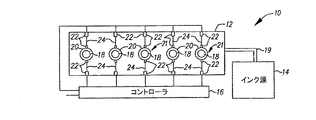
まず、図1に示す印刷装置10はプリントヘッド12、1個又は複数個のインク源14及びコントローラ16を備えている。本発明を実施するには、プリントヘッド12の素材としてシリコン等の半導体素材を使用し、その製造技術としてCMOS回路製造技術、MEMS(微細電子機械構造)製造技術等の既知半導体製造技術を使用するのが望ましいが、プリントヘッド12の形成に相応しい素材、相応しい製造技術であれば、従来既知のどのようなものでも使用することができる。
First, the
プリントヘッド12上にはノズル18が1個又は複数個形成されている。ヘッド12上には更にノズル18に通ずるインク流路19も設けられている。ノズル18はその流路19を介しインク源14に連通している。ヘッド12にインク源及びそれに対応するノズルを追加することで、多液滴グレースケール印刷、多インク色カラー印刷等も行うことができる。
One or a plurality of
ノズル18の近傍には液滴生成用励起器21が位置している。この励起器21は圧電アクチュエータ、熱アクチュエータ等として構成可能であり、図示例ではヒータ20が励起器21として用いられている。そのヒータ20は、少なくとも部分的にプリントヘッド12上に形成又は配置されており、対応するノズル18の周辺に位置している。そのノズル18の縁から径方向に沿ってやや離れた場所に配置することも可能だが、図示の通りノズル18に対し同心円をなすようそのノズル18の十分近くに配置するのが望ましい。その形状は略円環状(リンク状)にするのが望ましいが、弧状、方形等にすることもできる。図示例では、導体24を介し電極パッド22に導電接続された電気抵抗性発熱素子によって、そのヒータ20が好適に実現されている。
A droplet generating exciter 21 is located in the vicinity of the
導体24及び電極パッド22は少なくとも部分的にプリントヘッド12上に形成又は配置されている。これらはコントローラ16・ヒータ20間の電気的接続に使用されている。但し、これ以外の種々の周知手法でその電気的接続を実現することもできる。コントローラ16は例えばヒータ20用の電源といったデバイスである。そうした比較的単純な構成のデバイスに代え、より複雑な構成のデバイス、例えば論理コントローラ、プログラマブルマイクロプロセッサ等をコントローラ16として使用し、ヒータ20乃至励起器21を含む多数の部材を相応の形態で制御するようにしてもよい。
図2(a)及び(b)に、コントローラ16からヒータ20に印加される駆動用電気信号波形の従来例を示す。一般に、ヒータ20を高周波駆動すると小体積液滴26が生じ低周波駆動すると大体積液滴28が生じる。印刷にはそれらの液滴26,28のうち一方を使用する。他方は捕獲してインク回収乃至廃棄に回す。液滴26,28のどちらを印刷用にするかはその印刷装置の用途次第である。
2A and 2B show conventional examples of driving electric signal waveforms applied from the
印刷用液滴生成に当たりヒータ20に印加される電気信号は、例えば図2(a)に模式的に示す如き波形である。ノズル18からインクを吐出させる際、この信号でヒータ20を駆動すると、そのインクで図2(b)に模式的に示す如き大体積液滴28が形成される。即ち、その持続時間が0.1〜5μsec例えば1.0μsecで、その時間間隔34が例えば42μsecのヒータ駆動パルス32で駆動すると液滴28が発生する。また、非印刷用液滴生成に当たりヒータ20に印加される電気信号は、例えば図2(c)に模式的に示す如き波形である。この場合、パルス32としては例えばその持続時間が1.0μsec、時間間隔34が6.0μsecのパルスを使用する。これを含む非印刷用波形でヒータ20を駆動すると、図2(d)に模式的に示す如き小体積液滴26が発生する。なお、パルス32の持続時間を周期長=駆動パルスの持続時間+時間間隔で除した値は、従来からデューティ比として知られている。
The electrical signal applied to the
実際の画像データはこれらの混成であるので、画像データに基づきヒータ20を駆動する際そのヒータ20に印加される電気信号は、例えば図2(e)に模式的に示す如き波形となる。この波形には、印刷状態から非印刷状態への遷移や、非印刷状態から印刷状態への逆遷移が現れている。図2(f)に示したのはその結果生成されるインク滴流である。自明な通り、個々のヒータ20の動作は、ノズル18から吐出させるべきインクの色、印刷媒体Wに対するプリントヘッド12の動かし方、並びに印刷すべき画像に基づき個別に制御することができる。加えて、小体積液滴26及び大体積液滴28の体積は、インク種別、媒体種別、画像フォーマット、画像サイズ等の具体的印刷条件に応じ調整することができる。
Since the actual image data is a mixture of these, when the
このように画像データに応じ液滴の体積が変調されるようプリントヘッド12を作動させるに当たっては、図3に示すように、液滴をその体積に応じて印刷用経路と非印刷用経路に仕分けるシステム39を併用する。まず、ヘッド12上のノズルから吐出されたインクは作用流体フィラメント55となり、ヘッド12に対しほぼ直交するX軸沿いに移動していく。そのフィラメント55は、暫くの間はその状態を保ち続ける。図中のr1はその物理的区間を表している。ヒータ20(液滴生成用励起器21)を駆動する信号の周波数が画像データに応じ随時切り替わるので、フィラメント55は破断して小体積液滴26の流れとなる。それらの液滴26同士の合体による大体積液滴28の形成も始まる。図中のr2はそうしたフィラメント破断及びインク滴間合体が生じる区間を示している。液滴生成はこの区間r2の次の区間r3で完了する。この区間r3はそれに足る程度ヘッド12から離れた場所にあり、二種類のサイズ違い液滴即ち小体積液滴26及び大体積液滴28はここで概ねできあがる。システム39はそこに作用する。例えば、X軸に略直交する方向からその軸上にガス流を送り、区間r3の差し渡しと同等かそれ以下の差し渡しLを有する区間にてそのガス流による力46をインク滴流に及ぼす。大体積液滴28は小体積液滴26より質量及び慣性が大きいので、ガス力46が作用すると各液滴26,28はその体積及び質量に応じ互いに離隔していく。従って、ガス流の流速を適宜調整することで、液滴26が辿る経路Sを液滴28が辿る経路から十分な程度Dに隔たらせること、ひいては液滴28を印刷媒体Wに射突させつつ液滴26を前掲のインク捕獲機構で捉えることができる。インク捕獲機構の位置を少しずらせば、逆に、液滴26を媒体Wに射突させつつ液滴28を回収することもできる。
When the
例えば図4に示す構成では、大体積液滴28及び小体積液滴26を生み出すインク流をプリントヘッド12から吐出させ、形成されるインク滴流を概ね吐出経路X沿いに液滴偏向器40へと送り込んでいる。この偏向器40は上流室42及び下流室44を有しており、それらを用いその内部でガスの層流を発生させている。ポンプ60は、上流室42に加圧空気を送り込むことで、その下流にある下流室44へとガス流を流し込む。このガス流で、経路Xに沿ったインク滴流を外部空気による攪乱から守ることができる。真空ポンプ68は下流室44に通じており、そのガス流を引き込む役目を有している。偏向器40の中央は経路Xの近くにあり、ガス流による力46をそこでインク滴に作用させることで、小体積液滴経路Sと大体積液滴経路Kを離隔させることができる。
For example, in the configuration shown in FIG. 4, the ink flow that generates the
大体積液滴28はその後大体積液滴経路K沿いに移動し続け、プリントドラム58によって担持されている印刷媒体Wに向かっていく。他方、下流室44の片側壁のうち経路X近傍の部分には、小体積液滴経路Sを遮るようにインク回収機構48が配置されている。経路S沿いに移動中の小体積液滴26は機構48内の多孔質素子50、例えばワイヤスクリーン、メッシュ、焼成ステンレス鋼、セラミクス様素材等で形成された素子に射突する。その液滴26は、この素子50の窪みに毛細管力で引き込まれるので素子50の表面に大体積液滴が生じることはない。その素子50の背面には更にインク回収路52が通じており、その内部は下流室44内に比べ低いガス圧になっている。回収路52におけるこの減圧分は、素子50上の窪みからインクを吸い込むことができるよう、但し素子50を通る顕著な空気流は生じないよう設定されている。後者は、回収されるインクの発泡を抑えるためである。回収路52は更にインク回収室54に通じており、印刷に使用されなかったインク滴はここに回収される。回収されたインクはインク還流路56経由で回送され後に再利用される。このとき回収室54の内部にオープンセルスポンジ/フォーム64を入れておくと、プリントヘッド12で高速スキャンが行われる用途でも、インクの跳ねを防ぐことができる。また、この回収室54に真空吸引路62経由で負圧源を連結し、その負圧源で回収路52内に負圧を発生させることにより、上述したインク滴分離及びインク滴除去をより好適に行うことができる。
The
そのインク回収機構48の近傍におけるプリントヘッドアセンブリ内ガス圧は、室42,44を相応の構成にすると共に液滴偏向器40内のガス圧を調整することで、プリントドラム58近傍の外気圧に比し正寄りの圧力にすることができる。そうすることで、環境性塵埃や紙繊維が機構48に接近、付着することや、それらが下流室44に入ることを、妨げることができる。
The gas pressure in the print head assembly in the vicinity of the
そして、装置稼働時には、既知手法に従い且つプリントドラム58を用い、印刷媒体WをX軸と交差する方向沿いに移送する。この移送は印刷装置10の動きやプリントヘッド12の動きと協調させる。これは既知手法に従いコントローラ16の許に実行される。媒体Wとしては様々な素材のもの、例えば紙、ビニール、布、他種繊維性素材等の素材によるものを使用することができる。
When the apparatus is in operation, the print medium W is transferred along the direction intersecting the X axis according to a known method and using the
このように空気流偏向型のプリントヘッドを使用する連続式インクジェット印刷装置では、その体積比が所定の2の倍数になるよう液滴を生成する必要がある。例えば小体積液滴の体積をx相当値とし、その体積がNx相当値の大体積液滴を生成することが求められる(Nは2以上)。この構成では、破断によって生成される1x相当体積の小体積液滴をN個合体させるとNx相当体積の大体積液滴が1個発生する。以下の説明では、便宜上Nの値を=4とする。即ち大体積液滴の体積が4x相当値であると仮定して説明を行うこととする。 As described above, in a continuous ink jet printing apparatus using an air flow deflection type print head, it is necessary to generate droplets so that the volume ratio is a predetermined multiple of two. For example, it is required that the volume of a small volume droplet is an x equivalent value, and that a large volume droplet having a volume corresponding to an Nx value is generated (N is 2 or more). In this configuration, when N small volume droplets having a volume corresponding to 1x generated by breakage are combined, one large volume droplet having a volume corresponding to Nx is generated. In the following description, the value of N is set to = 4 for convenience. That is, the description will be made on the assumption that the volume of the large volume droplet is equivalent to 4x.
そうした液滴を生成する際には、従来から、液滴生成器に供給されたインクをオリフィスプレート上のノズルに通し、そのノズルの直径とほぼ等しい直径Dの流体柱を発生させる、という手法が採られている。この流体柱即ち流体ジェットは速度Vjetで移動していく。駆動パルスを励起器、例えばノズル周囲のヒータ20に印加すると、そのノズルにて流体ジェットの直径Dに擾乱が発生する。この擾乱も、そのジェットの移動につれ速度Vjetで移動していく。その励起器にパルスを更に印加すると、そのノズルにてその流体ジェットの直径Dに更なる擾乱が発生する。その擾乱もそのジェットの移動につれ速度Vjetで移動していく。周知の通り、流体ジェット上での擾乱同士の間隔がレイリー限界=約π*Dより広いと、その擾乱の振幅が大きくなっていき(その仕組みについては非特許文献1を参照されたい)、ある点まで大きくなるとその流体ジェットの一部が液滴となって分離していく。これに対し、擾乱同士の間隔がレイリー限界より狭いと擾乱振幅が小さくなっていくので、流体ジェットの破断による液滴生成は起こらない。
In order to generate such droplets, conventionally, there has been a method in which ink supplied to a droplet generator is passed through a nozzle on an orifice plate to generate a fluid column having a diameter D substantially equal to the diameter of the nozzle. It is taken. This fluid column or fluid jet moves at a velocity V jet . When the drive pulse is applied to an exciter, for example, the
このプロセスで4x相当体積の大体積液滴を1個生成した後1x相当体積の小体積液滴を8個生成する場合、駆動パルスの波形は例えば図5に示す波形とする。使用する駆動パルスの振幅、周期及びデューティ比は使用するインクの種類、そのインクに加える圧力、ノズルのサイズ並びに必要な液滴生成速度によって違い、例えば使用時インク温度が室温、インク圧力が52〜53psiで(1psi=約6.9kPa)使用する液滴生成器がオリフィス直径=15μm、基板厚=4μmの3.2インチアレイ長300jpi液滴生成器である場合(jpi=1インチ当たりジェット個数、1インチ=約2.54cm)、小体積液滴生成用の駆動パルスとしては、特に指定がない限り周波数=360kHz、振幅=直流3V(一定値)のパルスを使用するのが普通である。なお、図5に示したパルス波形の詳細については図6の表に示した波形データを参照されたい。キャリア周波数(繰返し周波数)Fcは30kHzにしてある。 When one large volume droplet having a volume corresponding to 4x is generated in this process and then eight small volume droplets having a volume corresponding to 1x are generated, the waveform of the drive pulse is, for example, the waveform shown in FIG. The amplitude, period and duty ratio of the drive pulse to be used vary depending on the type of ink to be used, the pressure applied to the ink, the size of the nozzle and the required droplet generation speed. For example, the ink temperature during use is room temperature and the ink pressure is 52 to If the drop generator used at 53 psi (1 psi = about 6.9 kPa) is a 3.2 inch array length 300 jpi drop generator with orifice diameter = 15 μm, substrate thickness = 4 μm (jpi = number of jets per inch, As a driving pulse for generating a small volume droplet, a pulse having a frequency = 360 kHz and an amplitude = DC 3V (constant value) is usually used unless otherwise specified. Refer to the waveform data shown in the table of FIG. 6 for details of the pulse waveform shown in FIG. The carrier frequency (repetition frequency) Fc is 30 kHz.
前述の通り、励起器に駆動パルスを印加すると流体ジェットに擾乱が生じる。例えば、図5に示した波形では、流体ジェット上に擾乱をもたらす2個目〜8個目の駆動パルスと、その次の駆動パルスまでに時間xが空いている。擾乱同士の時間間隔がxであるので、この第1種擾乱は大きくなって流体ジェットから破断し小体積液滴をもたらすこととなる。また、1個目の駆動パルスから2個目の駆動パルスまでの時間間隔は2個目〜8個目の駆動パルスからその次の駆動パルスまでの時間間隔のN倍(図示例ではN=4)であるので、1個目の駆動パルスによって流体ジェットの直径に引き起こされる擾乱即ち第2種擾乱の到来周期はNxとなる。この擾乱で発生する流体ジェット断片は、小体積液滴に比しN倍の体積を有する大体積液滴をもたらす。 As described above, when a driving pulse is applied to the exciter, the fluid jet is disturbed. For example, in the waveform shown in FIG. 5, time x is vacant between the second to eighth drive pulses that cause disturbance on the fluid jet and the next drive pulse. Since the time interval between the perturbations is x, this first type of perturbation becomes large and breaks from the fluid jet resulting in a small volume droplet. The time interval from the first drive pulse to the second drive pulse is N times the time interval from the second to eighth drive pulses to the next drive pulse (N = 4 in the illustrated example). Therefore, the arrival period of the disturbance caused by the first drive pulse in the diameter of the fluid jet, that is, the second type disturbance, is Nx. The fluid jet fragment generated by this disturbance results in a large volume droplet having a volume N times that of a small volume droplet.
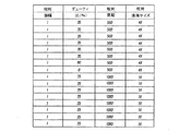
図6に示した波形データ中、第1列に列記されているのは各パルスの相対振幅であり、図示例ではどのパルスについても1値となっている。第2列に列記されているのはパルス毎のデューティ比(%)、第3列に列記されているのは各パルスの相対周期である。当該相対周期は波形生成器によるパルス記述に使用されるデータの点数で表現されている。その値から、表中の1個目のパルスがそれに続く8個のパルスのそれに比し4倍の周期であることを読み取ることができる。個々のパルスの実周期は、そのパルスの相対周期、波形全体の周期並びにキャリア周波数から求めることができる。例えば、1x相当体積、相対周期1000の小体積液滴が2.78μsecの周期を有しているのであれば、4x相当体積の大体積液滴の周期は11.11μsecとなる。前述した吐出条件の液滴生成器にこうした波形を印加すると、図7に示すパターンで液滴が発生する。 In the waveform data shown in FIG. 6, what is listed in the first column is the relative amplitude of each pulse, and in the example shown in the figure, it is a single value. Listed in the second column is the duty ratio (%) for each pulse, and listed in the third column is the relative period of each pulse. The relative period is expressed by the number of data points used for pulse description by the waveform generator. From this value, it can be read that the first pulse in the table has a period four times that of the following eight pulses. The actual period of each pulse can be obtained from the relative period of the pulse, the period of the entire waveform, and the carrier frequency. For example, if a small volume droplet having a volume equivalent to 1x and a relative period of 1000 has a period of 2.78 μsec, the period of a large volume droplet having a volume corresponding to 4x is 11.11 μsec. When such a waveform is applied to the droplet generator under the discharge conditions described above, droplets are generated in the pattern shown in FIG.
図7から読み取れるように、大体積液滴に成長しきれていない液滴同士の間では、小体積液滴同士の間隔が非常に不均等になる。また、大体積液滴になりきれていない3x相当体積の液滴は、この図から大きく右側にはみ出た個所に達しないと、その前方にある1x相当体積の小体積液滴のうち最も近いものと合体し、4x相当体積の大体積液滴に成長することができない。図8の表は、この液滴生成結果から算出した破断距離(BOL)、大体積液滴生成距離(LDFL)及び(不要)小体積液滴対小体積液滴合体距離(SD−SD)を表したものである。この他には、オリフィスからある程度離れた位置で小体積液滴と4x相当体積の大体積液滴が合体することもある。この不要な大体積液滴対小体積液滴合体距離(LD−SD)は、通常、中途体積液滴生成距離(PDFL)よりかなり長くなる。 As can be seen from FIG. 7, the intervals between the small-volume droplets are very uneven between the droplets that have not grown into large-volume droplets. In addition, a 3x equivalent volume droplet that has not become a large volume droplet does not reach the position that protrudes greatly to the right from this figure, and the closest one of the 1x equivalent volume small droplets in front of it And cannot grow into a large volume droplet having a volume equivalent to 4x. The table of FIG. 8 shows the breaking distance (BOL), large volume droplet generation distance (LDFL), and (unnecessary) small volume droplet to small volume droplet combination distance (SD-SD) calculated from the droplet generation result. It is a representation. In addition, a small volume droplet and a large volume droplet having a volume equivalent to 4 × may be combined at a position some distance from the orifice. This unwanted large volume droplet to small volume droplet coalescence distance (LD-SD) is typically much longer than the mid-volume droplet generation distance (PDFL).
そのため、液滴同士の合体を破断後可及的速やかに実行すること、特に1x相当体積の小体積液滴とNx相当体積の大体積液滴又は他の隣接小体積液滴との合体を伴わないようそれを実現することが望まれている。本発明では、特殊な波形の電圧/電流パルスを装置内の抵抗性ヒータに供給して液滴速度及び破断時点を操作することにより、連続式インクジェット印刷装置における小体積液滴及び大体積液滴の生成を次のように制御している。 For this reason, the uniting of the droplets is performed as soon as possible after the breakage, and in particular, the uniting of the small-volume droplet corresponding to 1x with the large-volume droplet corresponding to Nx or another adjacent small-volume droplet is involved. It is hoped that it will be realized. In the present invention, a special waveform voltage / current pulse is supplied to a resistive heater in the apparatus to manipulate the droplet velocity and break point, thereby enabling small and large volume droplets in a continuous inkjet printing apparatus. Is generated as follows.
その際には、まず、液滴生成器に供給されたインクを従来と同様にオリフィスプレート上のノズルに通し、それによってノズル直径とほぼ等しい直径Dの流体柱を発生させる。この流体柱即ち流体ジェットは速度Vjetで移動していく。駆動パルスを励起器、例えばノズル周囲のヒータに印加すると、そのノズルにて流体ジェットの直径Dに擾乱が発生する。この擾乱も、そのジェットの移動につれ速度Vjetで移動していく。その励起器にパルスを更に印加すると、そのノズルにてその流体ジェットの直径Dに更なる擾乱が発生する。その擾乱もそのジェットの移動につれ速度Vjetで移動していく。周知の通り、流体ジェット上での擾乱同士の間隔がレイリー限界=約π*Dより広いと、その擾乱の振幅が大きくなっていき(その仕組みについては非特許文献1を参照されたい)、ある点まで大きくなるとその流体ジェットの一部が液滴となって分離する。これに対し、擾乱同士の間隔がレイリー限界より狭いと、その擾乱の振幅は小さくなっていくので、流体ジェットの破断による液滴生成は起こらない。
In that case, first, the ink supplied to the droplet generator is passed through the nozzle on the orifice plate as in the conventional case, thereby generating a fluid column having a diameter D substantially equal to the nozzle diameter. This fluid column or fluid jet moves at a velocity V jet . When the drive pulse is applied to an exciter, for example, a heater around the nozzle, a disturbance occurs in the diameter D of the fluid jet at the nozzle. This disturbance also moves at a velocity V jet as the jet moves. As more pulses are applied to the exciter, further disturbances occur in the diameter D of the fluid jet at the nozzle. The disturbance also moves at a velocity V jet as the jet moves. As is well known, when the interval between the disturbances on the fluid jet is wider than the Rayleigh limit = about π * D, the amplitude of the disturbance increases (see
本発明では、それらの液滴の合体による大体積液滴の生成をより好適に行えるよう、また小体積液滴同士の間隔が安定的に均等になるよう、大体積液滴が生成されつつある期間に更に高周波の駆動パルス群たる駆動パルスバーストを差し挟む、という策を採っている。例えば、図5と図9の対比から明らかな通り、図5では1個目のパルスと2個目のパルスに挟まれた隙間になっていた期間に、図9では幅狭なパルスが複数個差し挟まれている。こうしてパルスを差し挟むと、流体ジェットの直径にまた別の擾乱即ち第3種擾乱がもたらされる。更に、その駆動パルスバーストを組成する個々のパルス(バーストモードパルス)は、先行するパルスに対し十分短い時間間隔で印加されているので、このパルスによって液滴の破断乃至損壊が生じることはない。即ち、流体ジェット上での第3種擾乱同士の間隔がπ*D未満になるような時間間隔で印加されているので、そのパルスで引き起こされる第3種擾乱は大きな振幅にならずに消滅していき、流体ジェットの破断ひいては小体積液滴の生成にはつながらない。このように、液滴生成の引き金にならないバーストモードパルスを挿入することで、合体プロセスを促進して大体積液滴をより好適に形成させることができる。 In the present invention, large-volume droplets are being generated so that large-volume droplets can be generated more appropriately by combining these droplets, and the intervals between the small-volume droplets are stably and evenly distributed. A measure is taken to sandwich a drive pulse burst, which is a higher frequency drive pulse group, during the period. For example, as is clear from the comparison between FIG. 5 and FIG. 9, in FIG. 5, there are a plurality of narrow pulses in the period between the first pulse and the second pulse. It is inserted. This intervening pulse causes another disturbance in the diameter of the fluid jet, a third type disturbance. Furthermore, since the individual pulses (burst mode pulse) composing the driving pulse burst are applied at a sufficiently short time interval with respect to the preceding pulse, the pulse does not cause breakage or breakage of the droplet. That is, since the third type disturbance on the fluid jet is applied at a time interval such that the interval between the disturbances is less than π * D, the third type disturbance caused by the pulse disappears without increasing the amplitude. It does not lead to the breakage of the fluid jet and hence the generation of small volume droplets. In this way, by inserting a burst mode pulse that does not trigger droplet generation, the coalescence process can be accelerated to form a large volume droplet more suitably.
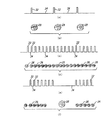
図9に示したのは本発明の一実施形態におけるパルス配置の例である。これは、1x相当体積の小体積液滴を8個、4x相当体積の大体積液滴を1個生成し、空気流による偏向に供する例である。本願では、大体積液滴生成期間中に印加される波形のことを大体積液滴バースト波形と呼んでいる。また、いわゆる当業者には自明な通り、小体積液滴や大体積液滴の発生個数は任意に設定することができる。波形データは図10たる表に列記した通りである。多くの場合、相応の周波数Fcを有するキャリアにこの波形を載せることとなろう。 FIG. 9 shows an example of pulse arrangement in one embodiment of the present invention. This is an example in which eight small volume droplets having a volume corresponding to 1x are generated and one large volume droplet having a volume corresponding to 4x are generated and subjected to deflection by an air flow. In the present application, a waveform applied during a large volume droplet generation period is called a large volume droplet burst waveform. As is obvious to those skilled in the art, the number of small volume droplets and large volume droplets generated can be set arbitrarily. The waveform data is as listed in the table of FIG. In many cases, this waveform will be placed on a carrier having a corresponding frequency Fc.
その大体積液滴バースト波形中の個々のバーストモードパルス、即ち図9に示すパルスのうち短い間隔で複数個並んでいる方のパルスは、他のパルスと同じデューティ比だがその持続時間は他のパルスの1/2になっている。即ち、バーストモードパルスの周波数の周波数は他のパルスの周波数の2倍になっている。これは、他のパルスのλ/D値が2π未満ならバーストモードパルスのλ/D値がπ未満になるということである。従って、バーストモードパルスの印加で流体ジェットがレイリー破断して液滴が生成されることはないが、生成される液滴に対しては図11中のバーストモードパルスも影響するので、図6に示した従来の波形で生成される液滴と図9に示したバースト波形で生成される液滴との間には幾つか特記すべき相違点が生じる。当該バースト波形でもたらされる変化としては、
1.大体積液滴に挟まれた小体積液滴同士の間隔がかなり均等になること
2.図12たる表に列記した如くLDFLが改善されかなり短くなること
3.SD−SDが計測対象域外にはみ出るほど改善されること
4.LD−SDが改善され従来波形によるLD−SDよりかなり長くなること
5.大体積液滴と後続の小体積液滴との間に液滴間隔異常が生じること
等がある。
The individual burst mode pulses in the large volume droplet burst waveform, that is, the pulse arranged in a short interval among the pulses shown in FIG. 9, has the same duty ratio as the other pulses, but the duration is other than It is half of the pulse. That is, the frequency of the burst mode pulse is twice that of the other pulses. This means that if the λ / D value of the other pulse is less than 2π, the λ / D value of the burst mode pulse is less than π. Accordingly, although the fluid jet does not undergo Rayleigh breakage by the application of the burst mode pulse, a droplet is not generated. However, the burst mode pulse in FIG. 11 also affects the generated droplet. There are some notable differences between the droplets generated with the conventional waveform shown and the droplets generated with the burst waveform shown in FIG. As a change brought about by the burst waveform,
1. 1. The intervals between small volume droplets sandwiched between large volume droplets should be fairly uniform. 2. LDFL is improved and considerably shortened as listed in the table of FIG. 3. SD-SD is improved so that it protrudes outside the measurement target area. 4. The LD-SD is improved and becomes considerably longer than the LD-SD with the conventional waveform. In some cases, an abnormality in the interval between droplets may occur between a large volume droplet and a subsequent small volume droplet.
図13に示したのは、本発明の他の実施形態におけるパルス配置の例である。この例では、図9〜図11に示した例で生じていた液滴間隔異常を正すため大体積液滴バースト波形に修正が施されている。即ち、差し挟まれる駆動パルスバースト中の最後尾パルスが、そのバースト中の他のパルスより大きなデューティ比を有するパルスに修正されている。この大体積液滴バースト波形に係る波形データは図14たる表に、またそのデューティ比修正が小体積液滴間隔に及ぼす作用は図15に、それぞれ示す通りである。 FIG. 13 shows an example of pulse arrangement in another embodiment of the present invention. In this example, the large volume droplet burst waveform is corrected in order to correct the droplet spacing abnormality that occurred in the examples shown in FIGS. That is, the last pulse in the intervening drive pulse burst is corrected to a pulse having a larger duty ratio than the other pulses in the burst. The waveform data relating to the large volume droplet burst waveform is shown in the table of FIG. 14, and the effect of the duty ratio correction on the small volume droplet interval is as shown in FIG.
見ての通り、図9に示した未修整の大体積液滴バースト波形ではなく、図13に示した修正版のそれを使用することで、小体積液滴間隔の異常を大きく抑圧し又は解消することができる。即ち、大体積液滴バースト波形中の最後尾パルスのデューティ比を35%から80%へと高めると、大体積液滴バースト波形中の最後尾パルスと小体積液滴生成用パルスのうち先頭のパルスとの間にある“オフ”時間の長さが、小体積液滴生成用パルス間にある“オフ”時間の長さにより近くなるため、小体積液滴間隔の異常が正されることになる。更に、図16たる表に示す通り、修正版の大体積液滴バースト波形を使用すると液滴生成能力が全体として高くなる。また、大体積液滴バースト波形の修正によりその最後尾パルスのデューティ比を35%から高める際に高める先を80%にしたのは、パルスのデューティ比をシステマティックに変化させながら液滴間隔及び液滴生成能力に及ぶ影響を観察した結果、80%という値が好成績であったからである。大体積液滴バースト波形中の最後尾パルスのデューティ比を10%から90%まで10%刻みで変化させていき、小体積液滴位置異常に対する影響を記録した結果を図17に示す。 As you can see, using the modified version shown in FIG. 13 instead of the unmodified large volume droplet burst waveform shown in FIG. 9, the small volume droplet spacing anomalies are greatly suppressed or eliminated. can do. That is, when the duty ratio of the last pulse in the large volume droplet burst waveform is increased from 35% to 80%, the last pulse in the large volume droplet burst waveform and the first pulse among the small volume droplet generation pulses are increased. Since the length of the “off” time between the pulses is closer to the length of the “off” time between the pulses for generating the small volume droplet, the abnormality of the small volume droplet interval is corrected. Become. Further, as shown in the table of FIG. 16, the use of a modified large volume droplet burst waveform increases the overall droplet generation capability. In addition, when the duty ratio of the last pulse is increased from 35% by modifying the large volume droplet burst waveform, the target to be increased to 80% is that the droplet interval and liquid are changed while systematically changing the pulse duty ratio. This is because, as a result of observing the influence on the droplet generation ability, a value of 80% was a good result. FIG. 17 shows the results of recording the influence on the small volume droplet position abnormality by changing the duty ratio of the last pulse in the large volume droplet burst waveform from 10% to 90% in increments of 10%.
なお、上掲の例では大体積液滴形成中に使用する駆動パルスバーストの周波数を小体積液滴形成用駆動パルスの周波数の2倍とすることで、小体積液滴生成時に生じる擾乱の周期に比し2倍の周期で均等間隔な擾乱が流体ジェット上に生じるようにしているが、本発明はこれ以外の周波数比でも実施することができる。 In the above example, the frequency of the disturbance generated at the time of generating the small volume droplet is set by making the frequency of the drive pulse burst used during the formation of the large volume droplet twice the frequency of the drive pulse for forming the small volume droplet. However, the present invention can be implemented with other frequency ratios, although disturbances that are evenly spaced are generated on the fluid jet at a period twice that of the above.
また、第3種擾乱の形態を要請に応じ設定乃至調整することで、実装先の連続式インクジェットシステムに独特の機能(他では要求されない機能)を必要に応じ提供することができる。例えば、図13に示した実施形態を拡張し、第3種擾乱をもたらすパルスのデューティ比を随時変化させるようにしてもよい。図18に示すようにデューティ比を漸増させた場合は合体距離がかなり短くなる。また、図19に示すように所要PDFL乃至LDFLに応じ個々のデューティ比を独立に設定及び調整するという非システマティックなやり方を採ることもできる。 Further, by setting or adjusting the type of the third type disturbance according to the request, a unique function (a function not required otherwise) can be provided as necessary in the continuous ink jet system at the mounting destination. For example, the embodiment shown in FIG. 13 may be expanded to change the duty ratio of the pulse that causes the third type disturbance as needed. As shown in FIG. 18, when the duty ratio is gradually increased, the combined distance is considerably shortened. Further, as shown in FIG. 19, it is possible to adopt a non-systematic method in which individual duty ratios are independently set and adjusted according to the required PDFL to LDFL.
更に、第3種擾乱の周期に変調を施し、擾乱毎にその周期を伸縮させるようにしてもよい。周期を個別に伸縮することでデューティ比も変調されることとなる。但し、そうした変調を実行する際には、Nx倍条件に違背しないよう第3種擾乱の個数を連動して変化させる必要がある。 Furthermore, the period of the third type disturbance may be modulated, and the period may be expanded and contracted for each disturbance. The duty ratio is also modulated by individually expanding and contracting the cycle. However, when performing such modulation, it is necessary to change the number of third type disturbances in conjunction with each other so as not to violate the Nx multiple condition.
Claims (5)
ノズル開口及び可調な励起器を有する液滴生成器を準備するステップと、
加圧された液体を液滴生成器に供給して所定直径Dの液体流をノズル開口から放出させるステップと、
液体流の直径に周期xの第1種擾乱が生じるよう励起器を作動させることで小体積液滴をその液体流から発生させるステップと、
液体流の直径に周期Nxの第2種擾乱が生じるよう励起器を作動させることで小体積液滴に比しその体積がN倍の大体積液滴をその液体流の断片から発生させるステップと、
生成途上の大体積液滴が破断しない程度に短い周期の第3種擾乱が液体流の直径に生じるよう、第2種擾乱によって大体積液滴が生成される前記周期Nxの間にその励起器を作動させるステップと、
を有する方法。 A method of generating a large volume droplet and a small volume droplet at any time by operating a droplet generator,
Providing a droplet generator having a nozzle opening and an adjustable exciter;
Supplying pressurized liquid to the droplet generator to discharge a liquid stream of a predetermined diameter D from the nozzle opening;
Generating a small volume droplet from the liquid stream by operating the exciter such that a first-type disturbance of period x occurs in the diameter of the liquid stream;
The step of the volume compared to the small volume droplets by the second type perturbation cycle Nx to the diameter of the liquid flow to create dynamic excitation device so that occurs to generate a large volume droplets N times from a fragment of the liquid stream When,
As the third type disturbance having a period shorter to the extent that large volume droplets generated developing no break occurs in the diameter of the liquid flow, excitation Niso between the periodic Nx a large volume droplet is generated by the second kind disturbances Operating the device;
Having a method.
Applications Claiming Priority (3)
| Application Number | Priority Date | Filing Date | Title |
|---|---|---|---|
| US11/749,187 US7828420B2 (en) | 2007-05-16 | 2007-05-16 | Continuous ink jet printer with modified actuator activation waveform |
| US11/749,187 | 2007-05-16 | ||
| PCT/US2008/006006 WO2008143810A1 (en) | 2007-05-16 | 2008-05-09 | Continuous printer with actuator activation waveform |
Publications (3)
| Publication Number | Publication Date |
|---|---|
| JP2010527300A JP2010527300A (en) | 2010-08-12 |
| JP2010527300A5 JP2010527300A5 (en) | 2011-06-30 |
| JP5426536B2 true JP5426536B2 (en) | 2014-02-26 |
Family
ID=39596434
Family Applications (1)
| Application Number | Title | Priority Date | Filing Date |
|---|---|---|---|
| JP2010508379A Active JP5426536B2 (en) | 2007-05-16 | 2008-05-09 | Continuous printer with improved actuator drive waveform |
Country Status (5)
| Country | Link |
|---|---|
| US (1) | US7828420B2 (en) |
| EP (1) | EP2144758B1 (en) |
| JP (1) | JP5426536B2 (en) |
| CN (1) | CN101678675B (en) |
| WO (1) | WO2008143810A1 (en) |
Families Citing this family (22)
| Publication number | Priority date | Publication date | Assignee | Title |
|---|---|---|---|---|
| US7938516B2 (en) * | 2008-08-07 | 2011-05-10 | Eastman Kodak Company | Continuous inkjet printing system and method for producing selective deflection of droplets formed during different phases of a common charge electrode |
| FR2971451B1 (en) * | 2011-02-11 | 2013-03-15 | Markem Imaje | STIMULATION RANGE DETECTION IN A CONTINUOUS INK JET PRINTER |
| BR112013030233A2 (en) * | 2011-05-25 | 2019-09-24 | Eastman Kodak Co | continuous liquid ejection system, and liquid droplet ejection method |
| US8469495B2 (en) | 2011-07-14 | 2013-06-25 | Eastman Kodak Company | Producing ink drops in a printing apparatus |
| US8801129B2 (en) | 2012-03-09 | 2014-08-12 | Eastman Kodak Company | Method of adjusting drop volume |
| US8646883B2 (en) * | 2012-03-20 | 2014-02-11 | Eastman Kodak Company | Drop placement error reduction in electrostatic printer |
| JP5601424B2 (en) * | 2012-03-30 | 2014-10-08 | ソニー株式会社 | Microparticle sorting apparatus and fluid stream optimization method in the apparatus |
| JP5924077B2 (en) | 2012-03-30 | 2016-05-25 | ソニー株式会社 | Fine particle sorting device and method for determining orbit direction in fine particle sorting device |
| CN104169708B (en) | 2013-01-28 | 2016-08-24 | 索尼公司 | Granule separator and microgranule method for separating |
| US10309891B2 (en) | 2013-10-16 | 2019-06-04 | Sony Corporation | Particle sorting apparatus, particle sorting method, and program |
| EP3690424B1 (en) | 2014-02-13 | 2023-12-27 | Sony Group Corporation | Particle sorting device, particle sorting method, and program |
| JP6657625B2 (en) | 2014-09-05 | 2020-03-04 | ソニー株式会社 | Droplet sorting apparatus, drop sorting method and program |
| US10419644B2 (en) | 2014-11-14 | 2019-09-17 | Sawgrass Technologies, Inc. | Digital image processing network |
| US9781307B2 (en) | 2014-11-14 | 2017-10-03 | Sawgrass Technologies, Inc. | Networked digital imaging customization |
| US10605714B2 (en) | 2015-10-19 | 2020-03-31 | Sony Corporation | Image processing device, fine particle sorting device, and image processing method |
| US10827097B2 (en) | 2015-11-02 | 2020-11-03 | Sawgrass Technologies, Inc. | Product imaging |
| US10827098B2 (en) | 2015-11-02 | 2020-11-03 | Sawgrass Technologies, Inc. | Custom product imaging method |
| WO2017130323A1 (en) | 2016-01-27 | 2017-08-03 | ギガフォトン株式会社 | Target supply device and extreme ultraviolet light generating device |
| US10499485B2 (en) | 2017-06-20 | 2019-12-03 | Asml Netherlands B.V. | Supply system for an extreme ultraviolet light source |
| WO2019013759A1 (en) * | 2017-07-11 | 2019-01-17 | Hewlett-Packard Development Company, L.P. | Fluid actuator evaluation based on actuator activation data |
| US10308013B1 (en) | 2017-12-05 | 2019-06-04 | Eastman Kodak Company | Controlling waveforms to reduce cross-talk between inkjet nozzles |
| WO2019180826A1 (en) | 2018-03-20 | 2019-09-26 | ギガフォトン株式会社 | Target supply device, extreme ultraviolet light generation device, and method for manufacturing electronic device |
Family Cites Families (11)
| Publication number | Priority date | Publication date | Assignee | Title |
|---|---|---|---|---|
| US1941001A (en) | 1929-01-19 | 1933-12-26 | Rca Corp | Recorder |
| US3373437A (en) | 1964-03-25 | 1968-03-12 | Richard G. Sweet | Fluid droplet recorder with a plurality of jets |
| US3709432A (en) | 1971-05-19 | 1973-01-09 | Mead Corp | Method and apparatus for aerodynamic switching |
| US6079821A (en) | 1997-10-17 | 2000-06-27 | Eastman Kodak Company | Continuous ink jet printer with asymmetric heating drop deflection |
| JP3475067B2 (en) * | 1998-02-02 | 2003-12-08 | 東芝テック株式会社 | Driving method of inkjet printer head |
| US6588888B2 (en) * | 2000-12-28 | 2003-07-08 | Eastman Kodak Company | Continuous ink-jet printing method and apparatus |
| US6505921B2 (en) * | 2000-12-28 | 2003-01-14 | Eastman Kodak Company | Ink jet apparatus having amplified asymmetric heating drop deflection |
| US6851796B2 (en) | 2001-10-31 | 2005-02-08 | Eastman Kodak Company | Continuous ink-jet printing apparatus having an improved droplet deflector and catcher |
| US6746108B1 (en) * | 2002-11-18 | 2004-06-08 | Eastman Kodak Company | Method and apparatus for printing ink droplets that strike print media substantially perpendicularly |
| FR2890596B1 (en) | 2005-09-13 | 2007-10-26 | Imaje Sa Sa | CHARGING DEVICE AND DROP DEFLECTION FOR INKJET PRINTING |
| US7673976B2 (en) | 2005-09-16 | 2010-03-09 | Eastman Kodak Company | Continuous ink jet apparatus and method using a plurality of break-off times |
-
2007
- 2007-05-16 US US11/749,187 patent/US7828420B2/en active Active
-
2008
- 2008-05-09 EP EP08754335.1A patent/EP2144758B1/en active Active
- 2008-05-09 WO PCT/US2008/006006 patent/WO2008143810A1/en active Application Filing
- 2008-05-09 CN CN2008800161684A patent/CN101678675B/en active Active
- 2008-05-09 JP JP2010508379A patent/JP5426536B2/en active Active
Also Published As
| Publication number | Publication date |
|---|---|
| JP2010527300A (en) | 2010-08-12 |
| CN101678675A (en) | 2010-03-24 |
| US20080284827A1 (en) | 2008-11-20 |
| CN101678675B (en) | 2011-12-14 |
| EP2144758B1 (en) | 2013-11-20 |
| EP2144758A1 (en) | 2010-01-20 |
| WO2008143810A1 (en) | 2008-11-27 |
| US7828420B2 (en) | 2010-11-09 |
Similar Documents
| Publication | Publication Date | Title |
|---|---|---|
| JP5426536B2 (en) | Continuous printer with improved actuator drive waveform | |
| EP1366902B1 (en) | Apparatus and method for improving gas flow uniformity in a continuous stream ink jet printer | |
| US6491362B1 (en) | Continuous ink jet printing apparatus with improved drop placement | |
| JP4847562B2 (en) | Image printing apparatus and method for separating ink droplets | |
| JP4117129B2 (en) | Ink jet device with amplified asymmetric heated droplet deflection | |
| EP1308278B1 (en) | A continuous ink-jet printing apparatus having an improved droplet deflector and catcher | |
| US6517197B2 (en) | Continuous ink-jet printing method and apparatus for correcting ink drop replacement | |
| US6793328B2 (en) | Continuous ink jet printing apparatus with improved drop placement | |
| US8033646B2 (en) | Liquid drop dispenser with movable deflector | |
| US20110109699A1 (en) | Liquid drop dispenser with movable deflector | |
| EP1260369A1 (en) | A continuous ink-jet printing method and apparatus with nozzle clusters | |
| EP2029363A1 (en) | Continuous ink jet printing with satellite droplets | |
| JP2003334957A (en) | Continuous inkjet method and apparatus | |
| US6739705B2 (en) | Continuous stream ink jet printhead of the gas stream drop deflection type having ambient pressure compensation mechanism and method of operation thereof |
Legal Events
| Date | Code | Title | Description |
|---|---|---|---|
| A521 | Request for written amendment filed |
Free format text: JAPANESE INTERMEDIATE CODE: A523 Effective date: 20110502 |
|
| A621 | Written request for application examination |
Free format text: JAPANESE INTERMEDIATE CODE: A621 Effective date: 20110502 |
|
| A521 | Request for written amendment filed |
Free format text: JAPANESE INTERMEDIATE CODE: A523 Effective date: 20120425 |
|
| A977 | Report on retrieval |
Free format text: JAPANESE INTERMEDIATE CODE: A971007 Effective date: 20130613 |
|
| A131 | Notification of reasons for refusal |
Free format text: JAPANESE INTERMEDIATE CODE: A131 Effective date: 20130618 |
|
| A521 | Request for written amendment filed |
Free format text: JAPANESE INTERMEDIATE CODE: A523 Effective date: 20130918 |
|
| TRDD | Decision of grant or rejection written | ||
| A01 | Written decision to grant a patent or to grant a registration (utility model) |
Free format text: JAPANESE INTERMEDIATE CODE: A01 Effective date: 20131119 |
|
| A61 | First payment of annual fees (during grant procedure) |
Free format text: JAPANESE INTERMEDIATE CODE: A61 Effective date: 20131128 |
|
| R150 | Certificate of patent or registration of utility model |
Free format text: JAPANESE INTERMEDIATE CODE: R150 Ref document number: 5426536 Country of ref document: JP Free format text: JAPANESE INTERMEDIATE CODE: R150 |
|
| R250 | Receipt of annual fees |
Free format text: JAPANESE INTERMEDIATE CODE: R250 |
|
| R250 | Receipt of annual fees |
Free format text: JAPANESE INTERMEDIATE CODE: R250 |
|
| R250 | Receipt of annual fees |
Free format text: JAPANESE INTERMEDIATE CODE: R250 |
|
| R250 | Receipt of annual fees |
Free format text: JAPANESE INTERMEDIATE CODE: R250 |
|
| R250 | Receipt of annual fees |
Free format text: JAPANESE INTERMEDIATE CODE: R250 |
|
| R250 | Receipt of annual fees |
Free format text: JAPANESE INTERMEDIATE CODE: R250 |
|
| R250 | Receipt of annual fees |
Free format text: JAPANESE INTERMEDIATE CODE: R250 |
|
| R250 | Receipt of annual fees |
Free format text: JAPANESE INTERMEDIATE CODE: R250 |