EP1452313A1 - Image recording apparatus - Google Patents
Image recording apparatus Download PDFInfo
- Publication number
- EP1452313A1 EP1452313A1 EP02786020A EP02786020A EP1452313A1 EP 1452313 A1 EP1452313 A1 EP 1452313A1 EP 02786020 A EP02786020 A EP 02786020A EP 02786020 A EP02786020 A EP 02786020A EP 1452313 A1 EP1452313 A1 EP 1452313A1
- Authority
- EP
- European Patent Office
- Prior art keywords
- image
- dividing line
- line shape
- section
- shape data
- Prior art date
- Legal status (The legal status is an assumption and is not a legal conclusion. Google has not performed a legal analysis and makes no representation as to the accuracy of the status listed.)
- Withdrawn
Links
Images


Classifications
-
- G—PHYSICS
- G06—COMPUTING OR CALCULATING; COUNTING
- G06K—GRAPHICAL DATA READING; PRESENTATION OF DATA; RECORD CARRIERS; HANDLING RECORD CARRIERS
- G06K15/00—Arrangements for producing a permanent visual presentation of the output data, e.g. computer output printers
- G06K15/02—Arrangements for producing a permanent visual presentation of the output data, e.g. computer output printers using printers
- G06K15/10—Arrangements for producing a permanent visual presentation of the output data, e.g. computer output printers using printers by matrix printers
-
- G—PHYSICS
- G06—COMPUTING OR CALCULATING; COUNTING
- G06K—GRAPHICAL DATA READING; PRESENTATION OF DATA; RECORD CARRIERS; HANDLING RECORD CARRIERS
- G06K15/00—Arrangements for producing a permanent visual presentation of the output data, e.g. computer output printers
- G06K15/02—Arrangements for producing a permanent visual presentation of the output data, e.g. computer output printers using printers
- G06K15/10—Arrangements for producing a permanent visual presentation of the output data, e.g. computer output printers using printers by matrix printers
- G06K15/102—Arrangements for producing a permanent visual presentation of the output data, e.g. computer output printers using printers by matrix printers using ink jet print heads
- G06K15/105—Multipass or interlaced printing
- G06K15/107—Mask selection
-
- H—ELECTRICITY
- H04—ELECTRIC COMMUNICATION TECHNIQUE
- H04N—PICTORIAL COMMUNICATION, e.g. TELEVISION
- H04N1/00—Scanning, transmission or reproduction of documents or the like, e.g. facsimile transmission; Details thereof
- H04N1/40—Picture signal circuits
- H04N1/401—Compensating positionally unequal response of the pick-up or reproducing head
- H04N1/4015—Compensating positionally unequal response of the pick-up or reproducing head of the reproducing head
-
- G—PHYSICS
- G06—COMPUTING OR CALCULATING; COUNTING
- G06K—GRAPHICAL DATA READING; PRESENTATION OF DATA; RECORD CARRIERS; HANDLING RECORD CARRIERS
- G06K2215/00—Arrangements for producing a permanent visual presentation of the output data
- G06K2215/111—Arrangements for producing a permanent visual presentation of the output data with overlapping swaths
Definitions
- the present invention relates to image recording apparatuses such as a printer, facsimile machine, and copier, particularly to an image recording apparatus in which a recording width is increased using a plurality of recording heads.
- An image recording apparatus of a photosensitive recording system, thermal transfer recording system, ink jet recording system or the like has been used in image recording apparatuses such as a printer and a copying machine.
- a recording head in which a large number of recording devices for printing dots are linearly arranged at equal intervals is used in these recording systems.
- Preparation of the recording head having a large recording length has a problem in that yield becomes worse and cost increases with a larger length, and it has been proposed that a recording width be extended using a large number of recording heads having a recording length shorter than a recording width.
- a method has been described in which a plurality of recording heads are linearly arranged in such a manner that end portions of the heads overlap with one another to a certain degree.
- a position from which the recording head is to be switched is irregularly set for each scanning line with respect to a region where the recording devices are redundant, so that joints become inconspicuous and the recording heads are easily arranged.
- An object of the present invention is to provide an image recording apparatus which can avoid image degradation because of conspicuous joints of images.
- an image recording apparatus comprising: a dividing line shape data generation section which produces dividing line shape data to divide input image data into a plurality of partial images; an image dividing section which divides the image data into a plurality of partial images based on the dividing line shape data produced in the dividing line shape data generation section; a density unevenness correction section which corrects density of the image data corresponding to divided portions produced by a dividing process in the image dividing section; and a recording section comprising a plurality of recording heads to record the respective partial images divided in the image dividing section.
- This constitution corresponds to a first embodiment described later.
- an image recording apparatus relates to the image recording apparatus according to the first aspect of the present invention, and the dividing line shape data output from the dividing line shape data generation section has a shape obtained by regularly moving a dividing position of the image data every line or every plurality of lines. This constitution corresponds to the first embodiment described later.
- an image recording apparatus relates to the image recording apparatus according to the first aspect of the present invention, and the dividing line shape data output from the dividing line shape data generation section has a shape obtained by irregularly moving a dividing position of the image data every line or every plurality of lines. This constitution corresponds to the first embodiment described later.
- an image recording apparatus relates to the image recording apparatus according to the second or third aspect of the present invention, and distribution of the dividing positions of the image data has a large distribution in a middle of a distribution range. This constitution corresponds to the first embodiment described later.
- an image recording apparatus relates to the image recording apparatus according to the second or third aspect of the present invention, and a maximum value of a difference of a line direction of the dividing position of the image data between adjacent lines is set to be not more than a predetermined value which is smaller than a width of a distribution range of the dividing positions of the image data.
- This constitution corresponds to the first embodiment described later.
- an image recording apparatus relates to the image recording apparatus according to the first aspect of the present invention, and the dividing line shape data generation section includes a storage device capable of storing the dividing line shape data. This constitution corresponds to the first embodiment described later.
- an image recording apparatus relates to the image recording apparatus according to the sixth aspect of the present invention, and the storage device is capable of rewriting the data.
- This constitution corresponds to the first embodiment described later.
- an image recording apparatus relates to the image recording apparatus according to the first aspect of the present invention, and the dividing line shape data generation section produces the dividing line shape data by a function or program. This constitution corresponds to the first embodiment described later.
- an image recording apparatus relates to the image recording apparatus according to the ninth aspect of the present invention, and the dividing line shape data is produced in such a manner that the dividing positions of the image data are not matched between colors in all lines.
- This constitution corresponds to the first embodiment described later.
- an image recording apparatus relates to the image recording apparatus according to the eleventh aspect of the present invention, and the dividing line shape data selection section selects the dividing line shape data in accordance with a type of an input image.
- This constitution corresponds to the second embodiment described later.
- an image recording apparatus relates to the image recording apparatus according to the eleventh aspect of the present invention, and the dividing line shape data selection section selects the dividing line shape data in accordance with a type of ink for use. This constitution corresponds to the second embodiment described later.
- an image recording apparatus relates to the image recording apparatus according to the eleventh aspect of the present invention, and the dividing line shape data selection section selects the dividing line shape data in accordance with a type of a recording medium for use. This constitution corresponds to the second embodiment described later.
- an image recording apparatus relates to the image recording apparatus according to the eleventh aspect of the present invention, and the dividing line shape data selection section selects the dividing line shape data in accordance with an image recording speed.
- This constitution corresponds to the second embodiment described later.
- an image recording apparatus relates to the image recording apparatus according to the first aspect of the present invention, and the density unevenness correction section controls on/off of a recording dot existing in a position contacting a dividing line to correct density unevenness of an image generated in a position corresponding to a joint of the recording heads so that a uniform density is obtained.
- This constitution corresponds to a third embodiment described later.
- an image recording apparatus relates to the image recording apparatus according to the first aspect of the present invention
- the density unevenness correction section includes a density unevenness correction amount storage section in which a correction amount of a density unevenness of an image generated in a position corresponding to a joint of the recording head is stored for various values of a phase difference of a recording device between two adjacent recording heads, refers to the correction amount stored in the density unevenness correction amount storage section, and acquires a density correction amount in accordance with an actually obtained phase difference to correct the density unevenness.
- This constitution corresponds to the third embodiment described later.
- an image recording apparatus relates to the image recording apparatus according to the seventeenth aspect of the present invention, and includes a phase difference detection section which detects the phase difference of the recording device between two adjacent recording heads. This constitution corresponds to the third embodiment described later.
- an image recording apparatus which controls the number of ink drops for use in forming recording dots so that gradation representation is possible for each recording dot, comprising: an image data storage section in which an image of each ink drop discharge for the gradation representation is stored; an image dividing line shape data storage section in which a plurality of different image dividing line shape data are stored; an image dividing line shape data selection section which selects one of the image dividing line shape data stored in the image dividing line shape data storage section in accordance with the number of image drops for the image stored in the image data storage section during forming of the recording dots; an image dividing section which divides image data stored in the image data storage section by the number of recording heads in accordance with the selected image dividing line shape data; and a recording section comprising a plurality of recording heads to record the image data divided in the image dividing section.
- the constitution corresponds to a fourth embodiment described later.
- an image recording apparatus relates to the image recording apparatus according to any one of the first to sixteenth aspects of the present invention, and comprises: a printing section which prints a test pattern for density unevenness correction measurement; a reading section which reads density of the test pattern printed in the printing section; and a calculation section which calculates density unevenness correction amount based on the density of the test pattern read in the reading section.
- a printing section which prints a test pattern for density unevenness correction measurement
- a reading section which reads density of the test pattern printed in the printing section
- a calculation section which calculates density unevenness correction amount based on the density of the test pattern read in the reading section.
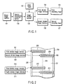
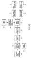
- FIG. 1 is a block diagram showing a first embodiment of the present invention.
- reference numeral 101 denotes a binary image memory which holds a binary image input into an image recording apparatus;
- 102 denotes a ROM table which holds dividing line shape data as a dividing line shape generation section;
- 103 denotes an image dividing section;
- 104 denotes a first divided image memory which holds divided images;
- 105 denotes a second divided image memory which holds the divided images;
- 106 denotes a first recording head which is a recording section;
- 107 denotes a second recording head which is a recording section; and
- 108 denotes a density unevenness correction section.
- each pixel is capable of taking signal levels in two ways of on (printing) and off (non-printing), and a distribution of on pixels represents shading of the image.
- FIG. 2 is a schematic diagram showing a positional relationship between a recording head and a recording medium.
- reference numeral 201 denotes a first divided image memory which holds the divided images
- 202 denotes a second divided image memory which holds the divided images. They correspond to 104, 105 of FIG. 1.
- Reference numerals 203, 204 denote recording heads, and correspond to 106, 107 of FIG. 1.
- a large number of recording devices 205 are linearly arranged in these recording heads 203, 204. These recording devices discharge ink to form recording dots constituting the image in a printer of an ink jet system.
- a recording medium 206 moves downward from above during image formation in the embodiment and, as a result, images 207, 208 are formed.
- the recording heads 203, 204 are arranged in such a manner that a part of a recordable region overlaps.
- a joint 209 of the formed image is connected so as to be inconspicuous by a process described later.
- recording heads 212, 213 are added.
- Reference numeral 210 denotes a divided image memory which holds the image data supplied to the recording head 212
- 211 denotes a divided image memory which holds the image data supplied to the recording head 213.
- FIG. 3A shows a state in the vicinity including the joint 209 of FIG. 2 in the binary image held by the binary image memory 101 of FIG. 1.
- Each circle 301 shows the image data for each pixel, and takes either on (printing) or off (non-printing) state.
- a broken line 302 shows a position of a dividing line represented by the dividing line shape data stored in the ROM table 102 of FIG. 1.
- the binary image held in the binary image memory 101 of FIG. 1 is subjected to density unevenness correction in the density unevenness correction section 108, and subsequently divided into two binary images along the dividing line shape data stored in the ROM table 102 of FIG. 1 in the image dividing section 103 of FIG. 1.
- the divided image data corresponding to a part of the image data shown in FIG. 3A changes as shown in FIGS. 3B, 3C.
- Two divided binary images are stored in the divided image memories, respectively, as shown by 104, 105 of FIG. 1, and recorded as images on a recording medium by the recording heads, respectively, as shown by 106, 107 of FIG. 1.
- the dividing line shape data stored beforehand in the ROM table 102 may have a regularly bent line shape as shown by 302 of FIG. 3A, or may also have a shape in which a dividing position irregularly moves for each line as shown by 401 in FIG. 4A.
- the recording device disposed on the recording head is very finely prepared to form a high-precision image.
- an interval of the recording device is about 70 ⁇ m.
- a positional relation of the recording device between two adjacent recording heads is various.
- FIG. 5A shows a positional relationship between two adjacent recording heads 203, 204 in a state in which the heads are disposed with a phase difference of 0 between the recording devices.
- FIG. 5B shows that two recording heads 203, 204 are disposed deviating in an approaching direction by a phase difference of a distance corresponding to 1/2 of a pixel pitch, that is, an interval between the recording devices.
- FIG. 5C shows that two recording heads 203, 204 are disposed deviating in a departing direction by a distance corresponding to 1/2 of the pixel pitch.
- Two states of FIGS. 5B and 5C have a difference for one dot between the positions, but the same phase state. That is, a disturbance of the pitch of the recording dots formed by two recording heads 203, 204 disposed adjacent to each other so that a part of a recordable range overlaps in an image position corresponding to the head joint can be set to ⁇ 0.5 dots or in any case.
- FIG. 6A when the interval between the formed recording dots is narrowed in the joint as shown in FIG. 5B, the dots formed on the recording medium in the vicinity of the joint are arranged as shown in FIG. 6A.
- Reference numeral 601 denotes the position of a dividing line shape. In this case, since a density of recording dots locally rises, the density of the joint rises.
- FIG. 5C when the interval between the formed recording dots is large in the joint, the dots formed on the recording medium in the vicinity of the joint are arranged as shown in FIG. 6B.
- Reference numeral 602 shows the position of the dividing line shape. In this case, since the density of the recording dots locally drops, the density of the joint drops.
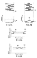
- FIGS. 7A, 7B are diagrams showing a distribution of positions where the dividing line divides the image along a line direction in the vicinity of the joint of the image.
- Reference numerals 703, 704 denote the positions of the dividing lines
- 701, 702 show the distribution of the positions where the image is divided by the dividing lines 703, 704.
- the positions wherein the dividing line divides the line of the image data are distributed a lot in a middle to obtain a distribution shape as shown by 702 of FIG. 7B. Accordingly, since the density unevenness strongly appears in the middle, but gradually disappears away from the middle, the boundary is inconspicuous, and image quality is enhanced.
- the data can be prepared when a pattern for measuring density unevenness is printed and a density corresponding to each position of the recording device is measured. Additionally, since the interval of the recording device is very small, it is difficult to correctly associate the position of density data measured for each recording device, and it is also considered that the density unevenness correction data is prepared in a state in which the corresponding position shifts.
- the positional shift of the actual density unevenness does not match that of the correction data in the portion of the end of the distribution, wrong correction is performed, and the image quality is degraded.
- FIG. 8A shows this state.
- 801 schematically shows an average density distribution with respect to a plurality of lines in the image formed from the image data having a uniform value in a state in which the interval between the recording dots is narrowed and the positions of the dividing line dividing the line of the image data are uniformly distributed
- 802 schematically shows the shape of correction data for correcting the density unevenness.
- FIG. 8B shows this state.
- 803 schematically shows an average density distribution in a case where the positions of the dividing line dividing the line of the image data are distributed a lot in the middle
- 804 schematically shows the shape of the correction data for correcting the density unevenness.
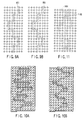
- FIG. 10 shows a joint of the image in which each recording dot is formed with spread. For convenience of description, the spread of each recording dot is shown in a rectangle, but in actual, the shape is nearly a circle. As shown in FIG.
- FIG. 11 shows a method of dividing the image data in a case where the image is formed in ink of two colors with respect to a partial image in the vicinity of the joint.
- 1101 shows the position of the dividing line shape of the image data for the first color
- 1102 shows the position of the dividing line shape of the image data for the second color.
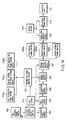
- FIG. 12 is a block diagram showing a second embodiment of the present invention.
- the reference numerals 101 to 107 are the same as those of FIG. 1.
- the ROM table 102 a plurality of dividing line shape data are held in accordance with various types of recording conditions.
- the density unevenness generated in the formed image is formed into data using the image scanner 110, and the image data read from the multivalued image memory 109 by the density unevenness correction section based on the data is subjected to the density unevenness correction, and output to the binarization section 111.
- the density unevenness is corrected, when a conversion table is disposed for each column of the image to convert the value of the image data.
- the binarization section 111 binarizes the image data subjected to the density unevenness correction to output the data to the binary image memory 101.
- an error diffusion method, dither method or the like is known as a method of converting a multivalued image into the binary image.
- the density unevenness correction section 108 adds or removes the recording dots with respect to first divided image data output from the image dividing section in accordance with the value of the phase difference output from the recording device phase difference detection section 113 to correct the density unevenness.
- the density unevenness correction section 108 does not print some of the recording dots in a position contacting the dividing line to correct the density unevenness.
- recording dots 901 shown by broken-line circles in FIG. 9A are thinned without being printed to correct the density.
- the amount of phase difference of the recording device between two adjacent heads and a degree of density unevenness generated in the joint between two heads have a certain relationship. Therefore, when an adequate value of a thinning ratio of the recording dots is checked with respect to various phase difference amounts beforehand once by an experiment, and subsequently an appropriate thinning ratio of the recording dots can be known with respect to a measured phase difference amount.
- the density unevenness correction section 108 adds the recording dots in the position contacting the dividing line to correct the density unevenness. For example, recording dots 902 shown by broken-line circles in FIG. 9B are added. A relation between the phase difference and an optimum value of the ratio of the recording dots to be added is also obtained beforehand by an experiment.
- the number of divided images are set to two, but the number of recording heads or the number of divided images may also be three or more.
- the image recording method a binary recording system has been described in which each recording dot is capable of obtaining only the on or off-state, but a multivalued recording system may also be used in which representation of three or more density gradations is possible for each recording dot.
- FIG. 14 is a block diagram showing a fourth embodiment of the present invention.
- reference numeral 1401 denotes an image memory which holds a 256-gradation input image
- 1402 denotes a gradation conversion section which converts a 256-gradation image into a 4-gradation image
- 1403 denotes a 4-gradation image memory which stores the 4-gradation image
- 1404 denotes a binarization section
- 1405 denotes a 2-gradation image memory which stores a 2-gradation image
- 1406 denotes an image dividing section which divides the image data by the number of recording heads
- 1407 denotes a storage memory selection section which selects a memory to store the divided image
- 1408(a) to (c) denote divided image memories which store the divided images
- 1409 denotes an image data selection section which selects the image data to be sent to a recording head driver described later
- 1410 denotes a recording head driver which controls the recording head
- 1411 denotes a
- the image is divided and recorded by a plurality of recording heads, and a plurality of sets of storage memory selection sections 1407, divided image memories 1408(a) to (c), image data selection sections 1409, recording head drivers 1410, and recording heads 1411 are disposed.
- the 256-gradation image data prepared by the user to record the image is stored in the 256-gradation image memory 1401 from a host computer (not shown) or the like.
- the gradation conversion section 1402 reads 256 gradation data from the 256-gradation image memory 1401, and converts the image into a 4-gradation image in which the values of pixels are integers of 0 to 3 to store the image in the 4-gradation image memory 1403.
- the value of the pixel of the image data stored in the 4-gradation image memory 1403 indicates the number of ink discharges at the time of the forming of the recording dots. That is, the ink discharge is not performed with the pixel having a value of 0, and the ink discharge is performed once to form the recording dot with the pixel having a value of 1. With a value of 2 or 3, the ink discharge is performed twice or three times to form the recording dot.
- the binarization section 1404 reads the image stored in the 4-gradation image memory 1403, and binarizes the image using a value of 1 to 3 output from the first counter 1413 as the threshold value to successively produce three images: a 2-gradation image in which only the pixel for performing the ink discharge once or more is set to 1 (ON) and the other pixels are set to 0 (OFF); a 2-gradation image in which only the pixel for performing the ink discharge twice or more is set to 1; and a 2-gradation image in which only the pixel for performing the ink discharge three times is set to 1 in accordance with the operation of the first counter.
- the dividing line shape data corresponding to these three images are stored in the first to third dividing line shape storage sections 1412(a) to (c). That is, the dividing line shape data for dividing the 2-gradation image in which only the pixel for performing the ink discharge once or more is set to 1 is stored in the first dividing line shape storage section 1412(a). The dividing line shape data for dividing the 2-gradation image in which only the pixel for performing the ink discharge twice or more is set to 1 is stored in the second dividing line shape storage section 1412(b). The dividing line shape data for dividing the 2-gradation image in which only the pixel for performing the ink discharge three times or more is set to 1 is stored in the third dividing line shape storage section 1412(c).
- the dividing line shape selection section 1414 selects one from the first to third dividing line shape storage sections 1412(a) to (c) in accordance with the value of 1 to 3 output from the first counter 1413, and reads the dividing line shape data stored in the section to output the data to the image dividing section 1406.
- the image dividing section 1406 divides the 2-gradation image stored in the 2-gradation image memory 1405 into the same number of images as that of recording heads in accordance with the dividing line shape data.
- the storage memory selection section 1407 stores the image divided by the image dividing section 1406 into any of the first to third divided image memories 1408(a) to (c) in accordance with the value of 1 to 3 output from the first counter 1413.
- the image data that has divided the 2-gradation image in which only the pixel for performing the ink discharge once or more is set to 1 is stored in the first divided image memory 1408(a).
- the image data that has divided the 2-gradation image in which only the pixel for performing the ink discharge twice or more is set to 1 is stored in the second divided image memory 1408(b).
- the image data that has divided the 2-gradation image in which only the pixel for performing the ink discharge three times is set to 1 is stored in the third divided image memory 1408(c).
- the second counter 1415 outputs a value of 1 to 3.
- the image data selection sections 1409 reads the divided image data from any of the first to third divided image memories 1408(a) to (c) in accordance with the output of the second counter 1415 to send the data to the recording head driver 1410. That is, the divided image data is read from the first divided image memory 1408(a) when an output of the second counter 1415 is 1, from the second divided image memory 1408(b) when an output of the second counter 1415 is 2, and from the third divided image memory 1408(c) when an output of the second counter 1415 is 3.
- the recording head driver 1410 drives the recording head 1411 to form the recording dot in a position corresponding the pixel having an image data value of 1 input from the image data selection section 1409.
- the recording is repeated three times in synchronization with the operation of the second counter 1415, and the recording dot is formed in which ink is superimposed by three ink discharges at maximum.
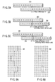
- the binarization section 1404 produces the 2-gradation image in which the pixel for performing the ink discharge once or more is set to 1. Therefore, as shown in FIG. 16A, the 2-gradation image including the pixel of 1 is prepared as shown by ⁇ . Since the first counter 1413 outputs 1, a dividing line shape 1601(a) stored in the first dividing line shape storage section 1412(a) is read in the dividing line shape selection section 1414, and the 2-gradation image is divided along the dividing line shape 1601(a) in the image dividing section 1406.
- a dividing line shape 1601(c) stored in the third dividing line shape storage section 1412(c) is read in the dividing line shape selection section 1414, and the 2-gradation image is divided along the dividing line shape 1601(c) in the image dividing section 1406.
- a dividing line shape generation section produces a dividing line shape having an inconspicuous joint by dividing/attaching of images, the image is accordingly divided, further subjected to density unevenness correction, and printed, so that image quality degradation by a conspicuous joint of the image can be avoided. Since a plurality of inexpensive recording heads each having a small recording length are used, and a trouble required for adjusting an attaching position of the recording head is saved, cost of an image recording apparatus can be reduced.
- the dividing line shape is regular, a capacity or program of a storage device required in the dividing line shape generation section can be reduced.
- the joint of the formed image is more inconspicuous.
- the density is higher or lower than a predetermined density in the joint of the formed image, the density smoothly changes, and therefore the joint is more inconspicuous.
- the dividing line shape generation section includes a storage device to store dividing line shape data, the dividing line shape data is prepared beforehand, and accordingly even a complicated shape is also usable.
- the shape can be rewritten into a dividing line shape suitable for conditions even in cases where recording conditions change such as a case where a recording medium having new characteristics is used.
- the dividing line shape is produced by a function or program requiring only a comparatively small storage capacity. Therefore, even when large dividing line shape data is used without any repetition, a large storage device for storing all the data is not required, the apparatus can be simplified, and the cost can be reduced.
- the dividing line shape can be selected and used from a plurality of shapes. Therefore, even when recording conditions change, it is possible to select and use the dividing line shape in which the joint of the formed image is most inconspicuous.
- the joint can be set to be inconspicuous using appropriate dividing line shape data with respect to any ink.
- the joint can be set to be inconspicuous using appropriate dividing line shape data with respect to any recording medium.
- the joint can be set to be inconspicuous using appropriate dividing line shape data with respect to any image recording speed.
- the unevenness of the density generated in the joint of the formed image is corrected based on a phase difference of a recording device between two adjacent recording heads causing the density unevenness. Therefore, when a relation between the phase difference and a density unevenness correction amount is checked beforehand, the density of the image does not have to be measured for each recording apparatus.
- the detection section to detect the phase difference of the recording device is not required except the image recording apparatus of the present invention, and the density unevenness generated in the joint of the formed image can be corrected.
- the density unevenness can be corrected only by the image recording apparatus of the present invention.
Landscapes
- Engineering & Computer Science (AREA)
- Physics & Mathematics (AREA)
- Mathematical Physics (AREA)
- General Engineering & Computer Science (AREA)
- General Physics & Mathematics (AREA)
- Theoretical Computer Science (AREA)
- Multimedia (AREA)
- Signal Processing (AREA)
- Ink Jet (AREA)
- Particle Formation And Scattering Control In Inkjet Printers (AREA)
- Accessory Devices And Overall Control Thereof (AREA)
Abstract
There is disclosed an image recording apparatus
comprising a density unevenness correction section
which corrects density unevenness of input image data,
a dividing line shape data generation section which
produces dividing line shape data to divide the image
data subjected to density unevenness correction into a
plurality of partial images, an image dividing section
which divides the image data into a plurality of
partial images based on the dividing line shape data
produced in the dividing line shape data generation
section, and a recording section comprising a plurality
of recording heads to record the respective partial
images output from the image dividing section, so that
it is possible to avoid image quality degradation by a
conspicuous joint of the image.
Description
The present invention relates to image recording
apparatuses such as a printer, facsimile machine, and
copier, particularly to an image recording apparatus in
which a recording width is increased using a plurality
of recording heads.
An image recording apparatus of a photosensitive
recording system, thermal transfer recording system,
ink jet recording system or the like has been used in
image recording apparatuses such as a printer and a
copying machine. A recording head in which a large
number of recording devices for printing dots are
linearly arranged at equal intervals is used in these
recording systems.
Preparation of the recording head having a large
recording length has a problem in that yield becomes
worse and cost increases with a larger length, and it
has been proposed that a recording width be extended
using a large number of recording heads having a
recording length shorter than a recording width. For
example, in Jpn. Pat. Appln. KOKAI Publication
No. 6-255175, a method has been described in which a
plurality of recording heads are linearly arranged in
such a manner that end portions of the heads overlap
with one another to a certain degree. A position from
which the recording head is to be switched is
irregularly set for each scanning line with respect to
a region where the recording devices are redundant, so
that joints become inconspicuous and the recording
heads are easily arranged.
However, in a conventional art, there has been a
problem that density of a recorded image sometimes
becomes higher or lower than a predetermined density in
the joints of the recording heads depending on the
arranged state of the recording heads, degrading the
quality of the image.
An object of the present invention is to provide
an image recording apparatus which can avoid image
degradation because of conspicuous joints of images.
According to a first aspect of the present
invention, there is provided an image recording
apparatus comprising: a dividing line shape data
generation section which produces dividing line shape
data to divide input image data into a plurality of
partial images; an image dividing section which divides
the image data into a plurality of partial images based
on the dividing line shape data produced in the
dividing line shape data generation section; a density
unevenness correction section which corrects density of
the image data corresponding to divided portions
produced by a dividing process in the image dividing
section; and a recording section comprising a plurality
of recording heads to record the respective partial
images divided in the image dividing section. This
constitution corresponds to a first embodiment
described later.
Moreover, an image recording apparatus according
to a second aspect of the present invention relates to
the image recording apparatus according to the first
aspect of the present invention, and the dividing line
shape data output from the dividing line shape data
generation section has a shape obtained by regularly
moving a dividing position of the image data every line
or every plurality of lines. This constitution
corresponds to the first embodiment described later.
Furthermore, an image recording apparatus
according to a third aspect of the present invention
relates to the image recording apparatus according to
the first aspect of the present invention, and the
dividing line shape data output from the dividing line
shape data generation section has a shape obtained by
irregularly moving a dividing position of the image
data every line or every plurality of lines. This
constitution corresponds to the first embodiment
described later.
Additionally, an image recording apparatus
according to a fourth aspect of the present invention
relates to the image recording apparatus according to
the second or third aspect of the present invention,
and distribution of the dividing positions of the image
data has a large distribution in a middle of a
distribution range. This constitution corresponds to
the first embodiment described later.
Moreover, an image recording apparatus according
to a fifth aspect of the present invention relates to
the image recording apparatus according to the second
or third aspect of the present invention, and a maximum
value of a difference of a line direction of the
dividing position of the image data between adjacent
lines is set to be not more than a predetermined value
which is smaller than a width of a distribution range
of the dividing positions of the image data. This
constitution corresponds to the first embodiment
described later.
Furthermore, an image recording apparatus
according to a sixth aspect of the present invention
relates to the image recording apparatus according to
the first aspect of the present invention, and the
dividing line shape data generation section includes a
storage device capable of storing the dividing line
shape data. This constitution corresponds to the first
embodiment described later.
Additionally, an image recording apparatus
according to a seventh aspect of the present invention
relates to the image recording apparatus according to
the sixth aspect of the present invention, and the
storage device is capable of rewriting the data. This
constitution corresponds to the first embodiment
described later.
Moreover, an image recording apparatus according
to an eighth aspect of the present invention relates to
the image recording apparatus according to the first
aspect of the present invention, and the dividing line
shape data generation section produces the dividing
line shape data by a function or program. This
constitution corresponds to the first embodiment
described later.
Furthermore, an image recording apparatus
according to a ninth aspect of the present invention
relates to the image recording apparatus according to
the first aspect of the present invention, the
recording section records data in multiple colors, and
the dividing line shape data generation section
produces the dividing line shape data which differs
with each color. This constitution corresponds to the
first embodiment described later.
Additionally, an image recording apparatus
according to a tenth aspect of the present invention
relates to the image recording apparatus according to
the ninth aspect of the present invention, and the
dividing line shape data is produced in such a manner
that the dividing positions of the image data are not
matched between colors in all lines. This constitution
corresponds to the first embodiment described later.
Moreover, an image recording apparatus according
to an eleventh aspect of the present invention relates
to the image recording apparatus according to the first
aspect of the present invention, and the dividing line
shape data generation section is capable of producing a
plurality of different dividing line shape data, and
comprises a dividing line shape data selection section
to select the produced dividing line shape data. This
constitution corresponds to a second embodiment
described later.
Furthermore, an image recording apparatus
according to a twelfth aspect of the present invention
relates to the image recording apparatus according to
the eleventh aspect of the present invention, and the
dividing line shape data selection section selects the
dividing line shape data in accordance with a type of
an input image. This constitution corresponds to the
second embodiment described later.
Additionally, an image recording apparatus
according to a thirteenth aspect of the present
invention relates to the image recording apparatus
according to the eleventh aspect of the present
invention, and the dividing line shape data selection
section selects the dividing line shape data in
accordance with a type of ink for use. This
constitution corresponds to the second embodiment
described later.
Moreover, an image recording apparatus according
to a fourteenth aspect of the present invention relates
to the image recording apparatus according to the
eleventh aspect of the present invention, and the
dividing line shape data selection section selects the
dividing line shape data in accordance with a type of a
recording medium for use. This constitution
corresponds to the second embodiment described later.
Furthermore, an image recording apparatus
according to a fifteenth aspect of the present
invention relates to the image recording apparatus
according to the eleventh aspect of the present
invention, and the dividing line shape data selection
section selects the dividing line shape data in
accordance with an image recording speed. This
constitution corresponds to the second embodiment
described later.
Additionally, an image recording apparatus
according to a sixteenth aspect of the present
invention relates to the image recording apparatus
according to the first aspect of the present invention,
and the density unevenness correction section controls
on/off of a recording dot existing in a position
contacting a dividing line to correct density
unevenness of an image generated in a position
corresponding to a joint of the recording heads so that
a uniform density is obtained. This constitution
corresponds to a third embodiment described later.
Moreover, an image recording apparatus according
to a seventeenth aspect of the present invention
relates to the image recording apparatus according to
the first aspect of the present invention, and the
density unevenness correction section includes a
density unevenness correction amount storage section in
which a correction amount of a density unevenness of an
image generated in a position corresponding to a joint
of the recording head is stored for various values of a
phase difference of a recording device between two
adjacent recording heads, refers to the correction
amount stored in the density unevenness correction
amount storage section, and acquires a density
correction amount in accordance with an actually
obtained phase difference to correct the density
unevenness. This constitution corresponds to the third
embodiment described later.
Furthermore, an image recording apparatus
according to an eighteenth aspect of the present
invention relates to the image recording apparatus
according to the seventeenth aspect of the present
invention, and includes a phase difference detection
section which detects the phase difference of the
recording device between two adjacent recording heads.
This constitution corresponds to the third embodiment
described later.
Moreover, according to a nineteenth aspect of the
present invention, there is provided an image recording
apparatus which controls the number of ink drops for
use in forming recording dots so that gradation
representation is possible for each recording dot,
comprising: an image data storage section in which an
image of each ink drop discharge for the gradation
representation is stored; an image dividing line shape
data storage section in which a plurality of different
image dividing line shape data are stored; an image
dividing line shape data selection section which
selects one of the image dividing line shape data
stored in the image dividing line shape data storage
section in accordance with the number of image drops
for the image stored in the image data storage section
during forming of the recording dots; an image dividing
section which divides image data stored in the image
data storage section by the number of recording heads
in accordance with the selected image dividing line
shape data; and a recording section comprising a
plurality of recording heads to record the image data
divided in the image dividing section. The
constitution corresponds to a fourth embodiment
described later.
Furthermore, an image recording apparatus
according to a twentieth aspect of the present
invention relates to the image recording apparatus
according to any one of the first to sixteenth aspects
of the present invention, and comprises: a printing
section which prints a test pattern for density
unevenness correction measurement; a reading section
which reads density of the test pattern printed in the
printing section; and a calculation section which
calculates density unevenness correction amount based
on the density of the test pattern read in the reading
section. This constitution corresponds to the second
embodiment described later.
FIG. 1 is a block diagram showing a first
embodiment of the present invention. In FIG. 1:
reference numeral 101 denotes a binary image memory
which holds a binary image input into an image
recording apparatus; 102 denotes a ROM table which
holds dividing line shape data as a dividing line shape
generation section; 103 denotes an image dividing
section; 104 denotes a first divided image memory which
holds divided images; 105 denotes a second divided
image memory which holds the divided images; 106
denotes a first recording head which is a recording
section; 107 denotes a second recording head which is a
recording section; and 108 denotes a density unevenness
correction section. In the binary image, each pixel is
capable of taking signal levels in two ways of on
(printing) and off (non-printing), and a distribution
of on pixels represents shading of the image.
FIG. 2 is a schematic diagram showing a positional
relationship between a recording head and a recording
medium. In FIG. 2, reference numeral 201 denotes a
first divided image memory which holds the divided
images, and 202 denotes a second divided image memory
which holds the divided images. They correspond to
104, 105 of FIG. 1.
A recording medium 206 moves downward from above
during image formation in the embodiment and, as a
result, images 207, 208 are formed. The recording
heads 203, 204 are arranged in such a manner that a
part of a recordable region overlaps. A joint 209 of
the formed image is connected so as to be inconspicuous
by a process described later. To perform multicolored
printing, only a required number of new recording
heads, for example, recording heads 212, 213 are added.
Reference numeral 210 denotes a divided image memory
which holds the image data supplied to the recording
head 212, and 211 denotes a divided image memory which
holds the image data supplied to the recording head
213.
FIG. 3A shows a state in the vicinity including
the joint 209 of FIG. 2 in the binary image held by the
binary image memory 101 of FIG. 1. Each circle 301
shows the image data for each pixel, and takes either
on (printing) or off (non-printing) state. A broken
line 302 shows a position of a dividing line
represented by the dividing line shape data stored in
the ROM table 102 of FIG. 1. The binary image held in
the binary image memory 101 of FIG. 1 is subjected to
density unevenness correction in the density unevenness
correction section 108, and subsequently divided into
two binary images along the dividing line shape data
stored in the ROM table 102 of FIG. 1 in the image
dividing section 103 of FIG. 1.
The divided image data corresponding to a part of
the image data shown in FIG. 3A changes as shown in
FIGS. 3B, 3C. Two divided binary images are stored in
the divided image memories, respectively, as shown by
104, 105 of FIG. 1, and recorded as images on a
recording medium by the recording heads, respectively,
as shown by 106, 107 of FIG. 1. The dividing line
shape data stored beforehand in the ROM table 102 may
have a regularly bent line shape as shown by 302 of
FIG. 3A, or may also have a shape in which a dividing
position irregularly moves for each line as shown by
401 in FIG. 4A.
Additionally, the recording device disposed on the
recording head is very finely prepared to form a
high-precision image. For example, with the recording
head for use in the recording at a resolution of 360
dpi, an interval of the recording device is about 70
µm. To dispose the recording head in a predetermined
position, unless the disposed position is finely
adjusted, a positional relation of the recording device
between two adjacent recording heads is various.
FIG. 5A shows a positional relationship between
two adjacent recording heads 203, 204 in a state in
which the heads are disposed with a phase difference of
0 between the recording devices. FIG. 5B shows that
two recording heads 203, 204 are disposed deviating in
an approaching direction by a phase difference of a
distance corresponding to 1/2 of a pixel pitch, that
is, an interval between the recording devices.
Furthermore, FIG. 5C shows that two recording heads
203, 204 are disposed deviating in a departing
direction by a distance corresponding to 1/2 of the
pixel pitch.
Two states of FIGS. 5B and 5C have a difference
for one dot between the positions, but the same phase
state. That is, a disturbance of the pitch of the
recording dots formed by two recording heads 203, 204
disposed adjacent to each other so that a part of a
recordable range overlaps in an image position
corresponding to the head joint can be set to ±0.5 dots
or in any case.
Additionally, when the interval between the formed
recording dots is narrowed in the joint as shown in
FIG. 5B, the dots formed on the recording medium in the
vicinity of the joint are arranged as shown in FIG. 6A.
Reference numeral 601 denotes the position of a
dividing line shape. In this case, since a density of
recording dots locally rises, the density of the joint
rises. As shown in FIG. 5C, when the interval between
the formed recording dots is large in the joint, the
dots formed on the recording medium in the vicinity of
the joint are arranged as shown in FIG. 6B. Reference
numeral 602 shows the position of the dividing line
shape. In this case, since the density of the
recording dots locally drops, the density of the joint
drops.
FIGS. 7A, 7B are diagrams showing a distribution
of positions where the dividing line divides the image
along a line direction in the vicinity of the joint of
the image. Reference numerals 703, 704 denote the
positions of the dividing lines, and 701, 702 show the
distribution of the positions where the image is
divided by the dividing lines 703, 704. When the
distribution of the positions for the dividing line to
divide the line of the image data is uniform as shown
by 701 of FIG. 7A, and the density unevenness occurs in
the overlapping portion of the recording heads, a
boundary between the overlapping portion of the
recording heads and another portion clearly appears and
becomes conspicuous.
On the other hand, the positions wherein the
dividing line divides the line of the image data are
distributed a lot in a middle to obtain a distribution
shape as shown by 702 of FIG. 7B. Accordingly, since
the density unevenness strongly appears in the middle,
but gradually disappears away from the middle, the
boundary is inconspicuous, and image quality is
enhanced.
In an example of a method of preparing density
unevenness correction data, the data can be prepared
when a pattern for measuring density unevenness is
printed and a density corresponding to each position of
the recording device is measured. Additionally, since
the interval of the recording device is very small, it
is difficult to correctly associate the position of
density data measured for each recording device, and it
is also considered that the density unevenness
correction data is prepared in a state in which the
corresponding position shifts. When deviations are
generated in the positions of actual density unevenness
and correction data, and the distribution of the
positions where the dividing line shape divides the
data of each line is uniform as shown in FIG. 7A, the
positional shift of the actual density unevenness does
not match that of the correction data in the portion of
the end of the distribution, wrong correction is
performed, and the image quality is degraded.
FIG. 8A shows this state. In FIG. 8A, 801
schematically shows an average density distribution
with respect to a plurality of lines in the image
formed from the image data having a uniform value in a
state in which the interval between the recording dots
is narrowed and the positions of the dividing line
dividing the line of the image data are uniformly
distributed, and 802 schematically shows the shape of
correction data for correcting the density unevenness.
However, when the dividing positions are distributed a
lot in the middle as shown in FIG. 7B, and even when
there is the positional shift between the actual
density unevenness and the correction data, the density
changes smoothly, and therefore image quality
degradation can be suppressed. FIG. 8B shows this
state. In the same manner as in FIG. 8A, in FIG. 8B,
803 schematically shows an average density distribution
in a case where the positions of the dividing line
dividing the line of the image data are distributed a
lot in the middle, and 804 schematically shows the
shape of the correction data for correcting the density
unevenness.
Additionally, when a plurality of recording heads
are driven on a moving recording medium to form an
image, a recording timing of each recording head is
controlled not to cause a printing positional shift in
a sheet conveying direction in an image position
corresponding to the joint of the recording head. When
a certain problem occurs, and the recording timing
shifts, a gap is made in a line direction, and the
image quality drops. FIG. 10 shows a joint of the
image in which each recording dot is formed with
spread. For convenience of description, the spread of
each recording dot is shown in a rectangle, but in
actual, the shape is nearly a circle. As shown in
FIG. 10A, when the position of the dividing line
dividing the line is largely distant between the
adjacent lines, a length of the gap also increases, and
a degree of the degradation of the image quality also
increases. However, as shown in FIG. 10B, when the
position of the dividing line dividing the line differs
little, the length of the gap also decreases, and the
degradation of the image quality can be suppressed. In
the example of FIG. 10B, the difference of the position
where the dividing line divides the line between the
adjacent lines is regulated to be three dots or less.
Next, a process will be described in a case where
a color image is formed using a plurality of colors of
ink. FIG. 11 shows a method of dividing the image data
in a case where the image is formed in ink of two
colors with respect to a partial image in the vicinity
of the joint. Usually, since a size or position of the
image data of a first color matches that of a second
color, they are superimposed and shown in the figure.
In FIG. 11, 1101 shows the position of the dividing
line shape of the image data for the first color, and
1102 shows the position of the dividing line shape of
the image data for the second color. When a plurality
of colors of ink are superimposed in this manner to
form the image, the positions of the dividing lines for
each color are displaced not to overlap with each
other, and accordingly the joint can be set to be
further inconspicuous.
FIG. 12 is a block diagram showing a second
embodiment of the present invention. In FIG. 12, the
reference numerals 101 to 107 are the same as those of
FIG. 1. Additionally, in the ROM table 102, a
plurality of dividing line shape data are held in
accordance with various types of recording conditions.
In FIG. 12: reference numeral 109 denotes a multivalued
image memory which holds an input multivalued image;
108 denotes a density unevenness correction section
which corrects density unevenness generated in a formed
image; 110 denotes an image scanner which is a density
unevenness detection section to extract data required
for the density unevenness correction; 111 denotes a
binarization section which converts a multivalued image
into a binary image; and 112 denotes a dividing line
shape selection section which selects a dividing line
shape suitable for recording conditions from a
plurality of dividing line shape data held in the ROM
table 102.
In the embodiment of the present invention, the
density unevenness generated in the formed image is
formed into data using the image scanner 110, and the
image data read from the multivalued image memory 109
by the density unevenness correction section based on
the data is subjected to the density unevenness
correction, and output to the binarization section 111.
The density unevenness is corrected, when a conversion
table is disposed for each column of the image to
convert the value of the image data.
The binarization section 111 binarizes the image
data subjected to the density unevenness correction to
output the data to the binary image memory 101. As a
method of converting a multivalued image into the
binary image, an error diffusion method, dither method
or the like is known.
The dividing line shape selection section 112 is
capable of inputting conditions concerning the image
formation, such as type of image, type of ink, type of
recording medium, and printing speed, and a user inputs
them in accordance with actual image forming
conditions. Moreover, the dividing line shape data
most suitable for the input conditions is selected from
the ROM table 102, and output to the image dividing
section 103.
For example, in the type of the image, an
irregular dividing line shape having a large
concave/convex width is selected in a photograph or the
like in which the joint is comparatively conspicuous.
In a character or line image in which the joint is
comparatively inconspicuous, a dividing line shape
having a small concave/convex width is selected. Then,
deformation of the character or line image can be
preferably reduced. The type of the ink, the type of
the recording medium, the image recording speed and the
like are concerned with blur or deformation of a
contour of the recording dot. When the contour of the
recording dot blurs comparatively little, the joint is
easily conspicuous, and therefore the dividing line
shape having a large concave/convex width is selected.
Conversely, when the contour of the recording dot blurs
comparatively largely, the joint is inconspicuous,
therefore the dividing line shape having a small
concave/convex width is selected, and then the
deformation of the image is preferably suppressed.
A combination of various conditions concerning the
image formation and the optimum dividing line shape is
clarified by an experiment, and the result may be
stored beforehand in the ROM table or the like. The
conditions concerning the image formation such as the
type of the image and the type of the recording medium
may also be automatically input using a sensor or the
like instead of the input by the user.
FIG. 13 is a block diagram showing a third
embodiment of the present invention. In FIG. 13, the
reference numerals 101 to 107 are the same as those of
FIG. 1. In FIG. 13, reference numeral 108 denotes a
density unevenness correction section, and 113 denotes
a recording device phase difference detection section
which detects the phase difference of the recording
device between two adjacent recording heads.
The recording device phase difference detection
section 113 comprises an image scanner, forms a
recording pattern for measurement on the same recording
medium with two adjacent recording heads, reads the
image by this image scanner to digitalize the interval
between the recording dots, and accordingly calculates
a periodic phase difference of the recording device
between two recording heads. As the recording pattern
for the measurement, for example, an image which is
formed by alternately turning on/off the recording
device for each apparatus and which has a stripe
pattern or the like is suitable.
The density unevenness correction section 108 adds
or removes the recording dots with respect to first
divided image data output from the image dividing
section in accordance with the value of the phase
difference output from the recording device phase
difference detection section 113 to correct the density
unevenness. As described in the first embodiment of
the present invention, when the phase difference of the
recording device between two adjacent recording heads
is in a state of FIG. 5B from that of FIG. 5A, the dot
density locally increases, and the joint seems to be
dense. In this case, the density unevenness correction
section 108 does not print some of the recording dots
in a position contacting the dividing line to correct
the density unevenness.
For example, recording dots 901 shown by broken-line
circles in FIG. 9A are thinned without being
printed to correct the density. The amount of phase
difference of the recording device between two adjacent
heads and a degree of density unevenness generated in
the joint between two heads have a certain
relationship. Therefore, when an adequate value of a
thinning ratio of the recording dots is checked with
respect to various phase difference amounts beforehand
once by an experiment, and subsequently an appropriate
thinning ratio of the recording dots can be known with
respect to a measured phase difference amount.
Moreover, conversely, when the phase difference of
the recording device between two adjacent recording
heads is in a state of FIG. 5C from that of FIG. 5A,
the dot density locally drops, and the density of the
joint seems to be small. In this case, the density
unevenness correction section 108 adds the recording
dots in the position contacting the dividing line to
correct the density unevenness. For example, recording
dots 902 shown by broken-line circles in FIG. 9B are
added. A relation between the phase difference and an
optimum value of the ratio of the recording dots to be
added is also obtained beforehand by an experiment.
When the recording dots in the position contacting
the dividing line are removed or added in this manner
to correct the deviation of the density generated in
the joint, the density of another portion is not
influenced, and therefore the image data can be
comparatively faithfully recorded.
It is to be noted that in any of the above-described
embodiments of the present invention, two
recording heads are used, the number of divided images
are set to two, but the number of recording heads or
the number of divided images may also be three or more.
As the image recording method, a binary recording
system has been described in which each recording dot
is capable of obtaining only the on or off-state, but a
multivalued recording system may also be used in which
representation of three or more density gradations is
possible for each recording dot.
FIG. 14 is a block diagram showing a fourth
embodiment of the present invention. In FIG. 14:
reference numeral 1401 denotes an image memory which
holds a 256-gradation input image; 1402 denotes a
gradation conversion section which converts a
256-gradation image into a 4-gradation image; 1403
denotes a 4-gradation image memory which stores the
4-gradation image; 1404 denotes a binarization section;
1405 denotes a 2-gradation image memory which stores a
2-gradation image; 1406 denotes an image dividing
section which divides the image data by the number of
recording heads; 1407 denotes a storage memory
selection section which selects a memory to store the
divided image; 1408(a) to (c) denote divided image
memories which store the divided images; 1409 denotes
an image data selection section which selects the image
data to be sent to a recording head driver described
later; 1410 denotes a recording head driver which
controls the recording head; 1411 denotes a recording
head; 1412(a) denotes a first dividing line shape
storage section which stores the shape of the dividing
line in dividing the image; 1412(b) denotes a second
dividing line shape storage section which stores the
shape of the dividing line in dividing the image;
1412(c) denotes a third dividing line shape storage
section which stores the shape of the dividing line in
dividing the image; 1413 denotes a first counter which
outputs values of 1 to 3 for use in a threshold value
of binarization in converting the 4-gradation image
into the 2-gradation image; 1414 denotes a dividing
line shape selection section which selects the dividing
line shape; and 1415 denotes a second counter which
outputs values of 1 to 3 for use in selecting the image
data for use in the recording.
It is to be noted that in the present invention,
the image is divided and recorded by a plurality of
recording heads, and a plurality of sets of storage
memory selection sections 1407, divided image memories
1408(a) to (c), image data selection sections 1409,
recording head drivers 1410, and recording heads 1411
are disposed.
The 256-gradation image data prepared by the user
to record the image is stored in the 256-gradation
image memory 1401 from a host computer (not shown) or
the like. In the image recording apparatus of the
embodiment of the present invention, four stages of
density gradation representations are performed for
each recording dot by four ways of zero to three ink
discharges for each recording dot. Therefore, the
gradation conversion section 1402 reads 256 gradation
data from the 256-gradation image memory 1401, and
converts the image into a 4-gradation image in which
the values of pixels are integers of 0 to 3 to store
the image in the 4-gradation image memory 1403.
In the gradation conversion, an error diffusion
method or the like is preferably used in order to
suppress the degradation of the image quality. The
value of the pixel of the image data stored in the
4-gradation image memory 1403 indicates the number of
ink discharges at the time of the forming of the
recording dots. That is, the ink discharge is not
performed with the pixel having a value of 0, and the
ink discharge is performed once to form the recording
dot with the pixel having a value of 1. With a value
of 2 or 3, the ink discharge is performed twice or
three times to form the recording dot.
The binarization section 1404 reads the image
stored in the 4-gradation image memory 1403, and
binarizes the image using a value of 1 to 3 output from
the first counter 1413 as the threshold value to
successively produce three images: a 2-gradation image
in which only the pixel for performing the ink
discharge once or more is set to 1 (ON) and the other
pixels are set to 0 (OFF); a 2-gradation image in which
only the pixel for performing the ink discharge twice
or more is set to 1; and a 2-gradation image in which
only the pixel for performing the ink discharge three
times is set to 1 in accordance with the operation of
the first counter.
Three produced 2-gradation images are successively
and temporarily stored in the 2-gradation image memory.
The dividing line shape data corresponding to these
three images are stored in the first to third dividing
line shape storage sections 1412(a) to (c). That is,
the dividing line shape data for dividing the
2-gradation image in which only the pixel for
performing the ink discharge once or more is set to 1
is stored in the first dividing line shape storage
section 1412(a). The dividing line shape data for
dividing the 2-gradation image in which only the pixel
for performing the ink discharge twice or more is set
to 1 is stored in the second dividing line shape
storage section 1412(b). The dividing line shape data
for dividing the 2-gradation image in which only the
pixel for performing the ink discharge three times or
more is set to 1 is stored in the third dividing line
shape storage section 1412(c).
The dividing line shape selection section 1414
selects one from the first to third dividing line shape
storage sections 1412(a) to (c) in accordance with the
value of 1 to 3 output from the first counter 1413, and
reads the dividing line shape data stored in the
section to output the data to the image dividing
section 1406. The image dividing section 1406 divides
the 2-gradation image stored in the 2-gradation image
memory 1405 into the same number of images as that of
recording heads in accordance with the dividing line
shape data.
The storage memory selection section 1407 stores
the image divided by the image dividing section 1406
into any of the first to third divided image memories
1408(a) to (c) in accordance with the value of 1 to 3
output from the first counter 1413.
That is, the image data that has divided the
2-gradation image in which only the pixel for
performing the ink discharge once or more is set to 1
is stored in the first divided image memory 1408(a).
The image data that has divided the 2-gradation image
in which only the pixel for performing the ink
discharge twice or more is set to 1 is stored in the
second divided image memory 1408(b). The image data
that has divided the 2-gradation image in which only
the pixel for performing the ink discharge three times
is set to 1 is stored in the third divided image memory
1408(c). The second counter 1415 outputs a value of 1
to 3.
The image data selection sections 1409 reads the
divided image data from any of the first to third
divided image memories 1408(a) to (c) in accordance
with the output of the second counter 1415 to send the
data to the recording head driver 1410. That is, the
divided image data is read from the first divided image
memory 1408(a) when an output of the second counter
1415 is 1, from the second divided image memory 1408(b)
when an output of the second counter 1415 is 2, and
from the third divided image memory 1408(c) when an
output of the second counter 1415 is 3.
The recording head driver 1410 drives the
recording head 1411 to form the recording dot in a
position corresponding the pixel having an image data
value of 1 input from the image data selection section
1409. The recording is repeated three times in
synchronization with the operation of the second
counter 1415, and the recording dot is formed in which
ink is superimposed by three ink discharges at maximum.
The dividing of the image will be described in
more detail with reference to FIGS. 15, 16A to 16C.
These figures show a part of the 4-gradation image
stored in the 4-gradation image memory 1403 in the
vicinity of the boundary between two adjacent recording
heads. In these figures, with a pixel shown by ⋄, the
recording dot is formed by the first ink discharge. In
the recording dot corresponding to pixel shown by ○,
further the second ink discharge is also performed to
increase the density of the recording dots. In the
recording dot corresponding to the pixel shown by □,
further the third ink discharge is also performed to
further increase the density of the recording dots, and
the recording dots are formed in a maximum density.
When the first counter 1413 outputs 1, the
binarization section 1404 produces the 2-gradation
image in which the pixel for performing the ink
discharge once or more is set to 1. Therefore, as
shown in FIG. 16A, the 2-gradation image including the
pixel of 1 is prepared as shown by ⋄. Since the first
counter 1413 outputs 1, a dividing line shape 1601(a)
stored in the first dividing line shape storage section
1412(a) is read in the dividing line shape selection
section 1414, and the 2-gradation image is divided
along the dividing line shape 1601(a) in the image
dividing section 1406.
Similarly, when the first counter 1413 outputs 2,
the binarization section 1404 produces the 2-gradation
image in which the pixel for performing the ink
discharge twice or more is set to 1. Therefore, as
shown in FIG. 16B, the binary image including the pixel
of 1 is prepared as shown by ○. Since the first
counter 1413 outputs 2, a dividing line shape 1601(b)
stored in the second dividing line shape storage
section 1412(b) is read in the dividing line shape
selection section 1414, and the 2-gradation image is
divided along the dividing line shape 1601(b) in the
image dividing section 1406. Further similarly, when
the first counter 1413 outputs 3, the binarization
section 1404 produces the 2-gradation image in which
the pixel for performing the ink discharge three times
is set to 1. Therefore, as shown in FIG. 16C, the
binary image including the pixel of 1 is prepared as
shown by □.
Since the first counter 1413 outputs 3, a dividing
line shape 1601(c) stored in the third dividing line
shape storage section 1412(c) is read in the dividing
line shape selection section 1414, and the 2-gradation
image is divided along the dividing line shape 1601(c)
in the image dividing section 1406.
In the embodiments of the present invention, since
four stages of density gradation representations are
performed for each recording dot, the gradation
conversion section 1402, 4-gradation image memory 1403,
first counter 1413, second counter 1415 and the like
are adapted to the 4-gradation image, but the present
invention is not limited to four stages of density
gradation representations, and is applicable to an
image recording apparatus which performs optional
density gradation representation such as eight
gradations.
Four embodiments have been described above, but,
needless to say, modifications in the scope of the
present invention are also included in the present
invention. When geometric correction of the image data
described in Jpn. Pat. Appln. KOKAI Publication
No. 2000-168109 or the like is used, distortion of the
image can be corrected to further enhance the image
quality.
According to the present invention, since a
dividing line shape generation section produces a
dividing line shape having an inconspicuous joint by
dividing/attaching of images, the image is accordingly
divided, further subjected to density unevenness
correction, and printed, so that image quality
degradation by a conspicuous joint of the image can be
avoided. Since a plurality of inexpensive recording
heads each having a small recording length are used,
and a trouble required for adjusting an attaching
position of the recording head is saved, cost of an
image recording apparatus can be reduced.
Moreover, since the dividing line shape is
regular, a capacity or program of a storage device
required in the dividing line shape generation section
can be reduced.
Furthermore, since the dividing line shape is
irregular, the joint of the formed image is more
inconspicuous.
Additionally, even when the density is higher or
lower than a predetermined density in the joint of the
formed image, the density smoothly changes, and
therefore the joint is more inconspicuous.
Moreover, even when a deviation is caused in a
recording timing between two adjacent heads in the
joint of the formed image, an area of a non-printed
portion generated between lines can be reduced, and
image quality can be inhibited from being degraded.
Furthermore, since the dividing line shape
generation section includes a storage device to store
dividing line shape data, the dividing line shape data
is prepared beforehand, and accordingly even a
complicated shape is also usable.
Additionally, since the dividing line shape data
is rewritable, the shape can be rewritten into a
dividing line shape suitable for conditions even in
cases where recording conditions change such as a case
where a recording medium having new characteristics is
used.
Moreover, the dividing line shape is produced by a
function or program requiring only a comparatively
small storage capacity. Therefore, even when large
dividing line shape data is used without any
repetition, a large storage device for storing all the
data is not required, the apparatus can be simplified,
and the cost can be reduced.
Furthermore, since the dividing line shape differs
with each color, the joint of the formed image is more
inconspicuous.
Additionally, since dividing positions of image
data do not match one another between the colors in all
the lines, the joint of the formed image is more
inconspicuous.
Moreover, the dividing line shape can be selected
and used from a plurality of shapes. Therefore, even
when recording conditions change, it is possible to
select and use the dividing line shape in which the
joint of the formed image is most inconspicuous.
Furthermore, since the dividing line shape data is
selected and used in accordance with the type of the
input image, the joint can be set to be inconspicuous
using appropriate dividing line shape data with respect
to any input image.
Additionally, since the dividing line shape data
is selected and used in accordance with a type of ink
for use, the joint can be set to be inconspicuous using
appropriate dividing line shape data with respect to
any ink.
Moreover, since the dividing line shape data is
selected and used in accordance with a type of a
recording medium for use, the joint can be set to be
inconspicuous using appropriate dividing line shape
data with respect to any recording medium.
Furthermore, since the dividing line shape data is
selected and used in accordance with an image recording
speed, the joint can be set to be inconspicuous using
appropriate dividing line shape data with respect to
any image recording speed.
Additionally, since the unevenness of the density
generated in the joint of the formed image is corrected
in the joint causing the density unevenness, a density
distribution of an original image can be more
faithfully reproduced.
Moreover, the unevenness of the density generated
in the joint of the formed image is corrected based on
a phase difference of a recording device between two
adjacent recording heads causing the density
unevenness. Therefore, when a relation between the
phase difference and a density unevenness correction
amount is checked beforehand, the density of the image
does not have to be measured for each recording
apparatus.
Furthermore, since a detection section is disposed
to detect the phase difference of the recording device
between two adjacent heads, the detection section to
detect the phase difference of the recording device is
not required except the image recording apparatus of
the present invention, and the density unevenness
generated in the joint of the formed image can be
corrected.
Additionally, since the joint of the formed image
differs with the number of ink discharges, the joint of
a multivalued recording image can be inconspicuous.
Moreover, since a printing section for printing a
test pattern for density unevenness correction
measurement, a reading section for reading the density
of the test pattern, and a calculation section for
calculating a density unevenness correction amount
based on the read density are disposed, the density
unevenness can be corrected only by the image recording
apparatus of the present invention.
Furthermore, when the image data described in Jpn.
Pat. Appln. KOKAI Publication No. 2000-168109 is
subjected to geometric correction or the like, the
image quality can further be enhanced.
Claims (20)
- An image recording apparatus comprising:a dividing line shape data generation section which produces dividing line shape data to divide input image data into a plurality of partial images;an image dividing section which divides the image data into a plurality of partial images based on the dividing line shape data produced in the dividing line shape data generation section;a density unevenness correction section which corrects density of the image data corresponding to divided portions produced by a dividing process in the image dividing section; anda recording section comprising a plurality of recording heads to record the respective partial images divided in the image dividing section.
- The image recording apparatus according to claim 1, wherein the dividing line shape data output from the dividing line shape data generation section has a shape obtained by regularly moving a dividing position of the image data every line or every plurality of lines.
- The image recording apparatus according to claim 1, wherein the dividing line shape data output from the dividing line shape data generation section has a shape obtained by irregularly moving a dividing position of the image data every line or every plurality of lines.
- The image recording apparatus according to claim 2 or 3, wherein distribution of the dividing positions of the image data has a large distribution in a middle of a distribution range.
- The image recording apparatus according to claim 2 or 3, wherein a maximum value of a difference of a line direction of the dividing position of the image data between adjacent lines is set to be not more than a predetermined value which is smaller than a width of a distribution range of the dividing positions of the image data.
- The image recording apparatus according to claim 1, wherein the dividing line shape data generation section includes a storage device capable of storing the dividing line shape data.
- The image recording apparatus according to claim 6, wherein the storage device is capable of rewriting the data.
- The image recording apparatus according to claim 1, wherein the dividing line shape data generation section produces the dividing line shape data by a function or program.
- The image recording apparatus according to claim 1, wherein the recording section records data in multiple colors, and the dividing line shape data generation section produces the dividing line shape data which differs with each color.
- The image recording apparatus according to claim 9, wherein the dividing line shape data is produced in such a manner that the dividing positions of the image data are not matched between colors in all lines.
- The image recording apparatus according to claim 1, wherein the dividing line shape data generation section is capable of producing a plurality of different dividing line shape data, and comprises a dividing line shape data selection section to select the produced dividing line shape data.
- The image recording apparatus according to claim 11, wherein the dividing line shape data selection section selects the dividing line shape data in accordance with a type of an input image.
- The image recording apparatus according to claim 11, wherein the dividing line shape data selection section selects the dividing line shape data in accordance with a type of ink for use.
- The image recording apparatus according to claim 11, wherein the dividing line shape data selection section selects the dividing line shape data in accordance with a type of a recording medium for use.
- The image recording apparatus according to claim 11, wherein the dividing line shape data selection section selects the dividing line shape data in accordance with an image recording speed.
- The image recording apparatus according to claim 1, wherein the density unevenness correction section controls on/off of a recording dot existing in a position contacting a dividing line to correct density unevenness of an image generated in a position corresponding to a joint of the recording heads so that a uniform density is obtained.
- The image recording apparatus according to claim 1, wherein the density unevenness correction section includes a density unevenness correction amount storage section in which a correction amount of a density unevenness of an image generated in a position corresponding to a joint of the recording head is stored for various values of a phase difference of a recording device between two adjacent recording heads, refers to the correction amount stored in the density unevenness correction amount storage section, and acquires a density correction amount in accordance with an actually obtained phase difference to correct the density unevenness.
- The image recording apparatus according to claim 17, further comprising: a phase difference detection section which detects the phase difference of the recording device between two adjacent recording heads.
- An image recording apparatus which controls the number of ink drops for use in forming recording dots so that gradation representation is possible for each recording dot, comprising:an image data storage section in which an image of each ink drop discharge for the gradation representation is stored;an image dividing line shape data storage section in which a plurality of different image dividing line shape data are stored;an image dividing line shape data selection section which selects one of the image dividing line shape data stored in the image dividing line shape data storage section in accordance with the number of image drops for the image stored in the image data storage section during the forming of the recording dots;an image dividing section which divides image data stored in the image data storage section by the number of recording heads in accordance with the selected image dividing line shape data; anda recording section comprising a plurality of recording heads to record the image data divided in the image dividing section.
- The image recording apparatus according to any of claims 1 to 16, further comprising:a printing section which prints a test pattern for density unevenness correction measurement;a reading section which reads density of the test pattern printed in the printing section; anda calculation section which calculates density unevenness correction amount based on the density of the test pattern read in the reading section.
Applications Claiming Priority (3)
| Application Number | Priority Date | Filing Date | Title |
|---|---|---|---|
| JP2001368939A JP2003165263A (en) | 2001-12-03 | 2001-12-03 | Image recording device |
| JP2001368939 | 2001-12-03 | ||
| PCT/JP2002/012639 WO2003047867A1 (en) | 2001-12-03 | 2002-12-03 | Image recording apparatus |
Publications (2)
| Publication Number | Publication Date |
|---|---|
| EP1452313A1 true EP1452313A1 (en) | 2004-09-01 |
| EP1452313A4 EP1452313A4 (en) | 2010-12-01 |
Family
ID=19178430
Family Applications (1)
| Application Number | Title | Priority Date | Filing Date |
|---|---|---|---|
| EP02786020A Withdrawn EP1452313A4 (en) | 2001-12-03 | 2002-12-03 | Image recording apparatus |
Country Status (4)
| Country | Link |
|---|---|
| US (1) | US20040218200A1 (en) |
| EP (1) | EP1452313A4 (en) |
| JP (1) | JP2003165263A (en) |
| WO (1) | WO2003047867A1 (en) |
Cited By (16)
| Publication number | Priority date | Publication date | Assignee | Title |
|---|---|---|---|---|
| WO2006044530A1 (en) | 2004-10-15 | 2006-04-27 | Fujifilm Dimatix, Inc. | Print systems and techniques |
| WO2006044598A3 (en) * | 2004-10-15 | 2006-08-17 | Dimatix Inc | Data pump for printing |
| WO2006044597A3 (en) * | 2004-10-15 | 2007-01-25 | Dimatix Inc | Printing system software architecture |
| WO2006049836A3 (en) * | 2004-10-29 | 2007-02-01 | Dimatix Inc | Tailoring image data packets to properties of print heads |
| EP2046011A3 (en) * | 2007-10-01 | 2009-04-29 | Brother Kogyo Kabushiki Kaisha | Control apparatus, image forming apparatus and image forming method |
| EP2057587A1 (en) * | 2006-10-03 | 2009-05-13 | Xaar Technology Limited | Printer and method for printing |
| US7722147B2 (en) | 2004-10-15 | 2010-05-25 | Fujifilm Dimatix, Inc. | Printing system architecture |
| WO2011011038A1 (en) * | 2009-07-20 | 2011-01-27 | Eastman Kodak Company | Method for reducing jet module stitch error |
| WO2011022035A1 (en) * | 2009-08-19 | 2011-02-24 | Eastman Kodak Company | Improved merging of image pixel arrangements |
| US8025354B2 (en) | 2008-06-06 | 2011-09-27 | Fujifilm Dimatix, Inc. | Sensing objects for printing |
| US8068245B2 (en) * | 2004-10-15 | 2011-11-29 | Fujifilm Dimatix, Inc. | Printing device communication protocol |
| US8251471B2 (en) | 2003-08-18 | 2012-08-28 | Fujifilm Dimatix, Inc. | Individual jet voltage trimming circuitry |
| CN103909740A (en) * | 2013-01-04 | 2014-07-09 | 研能科技股份有限公司 | Automatic printing correction method suitable for page width printing device |
| DE102013007294A1 (en) * | 2013-04-26 | 2014-10-30 | Heidelberger Druckmaschinen Ag | Method for producing a printed image composed of sections |
| WO2015185145A1 (en) * | 2014-06-05 | 2015-12-10 | Hewlett-Packard Development Company, L.P. | Page-wide array printing |
| WO2018077536A1 (en) * | 2016-10-25 | 2018-05-03 | Memjet Technology Limited | Method of minimizing stitching artifacts for overlapping printhead segments |
Families Citing this family (15)
| Publication number | Priority date | Publication date | Assignee | Title |
|---|---|---|---|---|
| JP5754873B2 (en) | 2007-08-07 | 2015-07-29 | キヤノン株式会社 | Recording control apparatus and calibration method |
| JP2009061621A (en) * | 2007-09-05 | 2009-03-26 | Seiko Epson Corp | Liquid ejecting apparatus and liquid ejecting method |
| JP2009090610A (en) * | 2007-10-12 | 2009-04-30 | Roland Dg Corp | Image forming apparatus |
| JP4986976B2 (en) * | 2007-12-20 | 2012-07-25 | キヤノン株式会社 | Image processing apparatus, image forming apparatus, and image processing method |
| JP5053903B2 (en) * | 2008-03-31 | 2012-10-24 | キヤノン株式会社 | Image processing apparatus and method |
| JP2010131855A (en) * | 2008-12-04 | 2010-06-17 | Seiko Epson Corp | Image processing apparatus, image processing method, and image forming apparatus |
| JP5504628B2 (en) * | 2008-12-26 | 2014-05-28 | セイコーエプソン株式会社 | Method for manufacturing fluid ejecting apparatus, correction value setting method for fluid ejecting apparatus, and fluid ejecting apparatus |
| JP5644048B2 (en) * | 2008-12-26 | 2014-12-24 | セイコーエプソン株式会社 | Method for manufacturing fluid ejecting apparatus, correction value setting method for fluid ejecting apparatus, and fluid ejecting apparatus |
| JP5733883B2 (en) * | 2009-04-07 | 2015-06-10 | キヤノン株式会社 | Inkjet recording apparatus and inkjet recording method |
| JP2015016671A (en) * | 2013-07-12 | 2015-01-29 | セイコーエプソン株式会社 | Dot recording apparatus, dot recording method, and computer program therefor |
| JP2015089629A (en) | 2013-11-05 | 2015-05-11 | キヤノン株式会社 | RECORDING CONTROL DEVICE, RECORDING DEVICE, AND RECORDING METHOD |
| JP6569418B2 (en) * | 2015-09-17 | 2019-09-04 | コニカミノルタ株式会社 | Inkjet recording apparatus and inkjet recording method |
| US9908324B1 (en) | 2017-02-27 | 2018-03-06 | Eastman Kodak Company | Printing with overlapping printheads |
| WO2018168192A1 (en) * | 2017-03-16 | 2018-09-20 | コニカミノルタ株式会社 | Inkjet recording device and inkjet recording method |
| JP6673438B2 (en) * | 2018-11-07 | 2020-03-25 | ブラザー工業株式会社 | Inkjet printer |
Family Cites Families (11)
| Publication number | Priority date | Publication date | Assignee | Title |
|---|---|---|---|---|
| JPH0635192B2 (en) * | 1984-11-19 | 1994-05-11 | キヤノン株式会社 | Recording device |
| JPH02238951A (en) * | 1989-03-13 | 1990-09-21 | Canon Inc | Image recording method and device |
| JPH06255175A (en) * | 1993-03-08 | 1994-09-13 | Fuji Xerox Co Ltd | Recording apparatus |
| US5630027A (en) * | 1994-12-28 | 1997-05-13 | Texas Instruments Incorporated | Method and apparatus for compensating horizontal and vertical alignment errors in display systems |
| JP3556351B2 (en) * | 1995-10-05 | 2004-08-18 | オリンパス株式会社 | Image forming device |
| JP3245361B2 (en) * | 1996-07-30 | 2002-01-15 | キヤノン株式会社 | Image recording apparatus and image recording system |
| JP4298836B2 (en) * | 1998-06-30 | 2009-07-22 | 東芝テック株式会社 | Inkjet recording device |
| JP2000103053A (en) * | 1998-09-30 | 2000-04-11 | Olympus Optical Co Ltd | Image forming device |
| JP2000168109A (en) * | 1998-12-11 | 2000-06-20 | Olympus Optical Co Ltd | Image correction device |
| JP3702711B2 (en) * | 1999-06-18 | 2005-10-05 | セイコーエプソン株式会社 | Printing apparatus and printing method |
| JP2002103597A (en) * | 2000-07-25 | 2002-04-09 | Sony Corp | Printer and printer head |
-
2001
- 2001-12-03 JP JP2001368939A patent/JP2003165263A/en active Pending
-
2002
- 2002-12-03 EP EP02786020A patent/EP1452313A4/en not_active Withdrawn
- 2002-12-03 WO PCT/JP2002/012639 patent/WO2003047867A1/en not_active Ceased
-
2004
- 2004-06-02 US US10/860,712 patent/US20040218200A1/en not_active Abandoned
Cited By (37)
| Publication number | Priority date | Publication date | Assignee | Title |
|---|---|---|---|---|
| US8251471B2 (en) | 2003-08-18 | 2012-08-28 | Fujifilm Dimatix, Inc. | Individual jet voltage trimming circuitry |
| CN101901119B (en) * | 2004-10-15 | 2012-02-01 | 富士胶卷迪马蒂克斯股份有限公司 | Method for controlling high bandwidth printing of a remote printer |
| WO2006044597A3 (en) * | 2004-10-15 | 2007-01-25 | Dimatix Inc | Printing system software architecture |
| US8259334B2 (en) | 2004-10-15 | 2012-09-04 | Fujifilm Dimatix, Inc. | Data pump for printing |
| WO2006044530A1 (en) | 2004-10-15 | 2006-04-27 | Fujifilm Dimatix, Inc. | Print systems and techniques |
| WO2006044598A3 (en) * | 2004-10-15 | 2006-08-17 | Dimatix Inc | Data pump for printing |
| US7911625B2 (en) | 2004-10-15 | 2011-03-22 | Fujifilm Dimatrix, Inc. | Printing system software architecture |
| CN101052942B (en) * | 2004-10-15 | 2010-05-12 | 富士胶卷迪马蒂克斯股份有限公司 | Printing system software system |
| US7722147B2 (en) | 2004-10-15 | 2010-05-25 | Fujifilm Dimatix, Inc. | Printing system architecture |
| CN101091153B (en) * | 2004-10-15 | 2010-06-16 | 富士胶卷迪马蒂克斯股份有限公司 | data pump for printing |
| US8085428B2 (en) * | 2004-10-15 | 2011-12-27 | Fujifilm Dimatix, Inc. | Print systems and techniques |
| US8068245B2 (en) * | 2004-10-15 | 2011-11-29 | Fujifilm Dimatix, Inc. | Printing device communication protocol |
| US7907298B2 (en) * | 2004-10-15 | 2011-03-15 | Fujifilm Dimatix, Inc. | Data pump for printing |
| CN100483327C (en) * | 2004-10-29 | 2009-04-29 | 富士胶卷迪马蒂克斯股份有限公司 | Printing system and printing method |
| WO2006049836A3 (en) * | 2004-10-29 | 2007-02-01 | Dimatix Inc | Tailoring image data packets to properties of print heads |
| US8199342B2 (en) | 2004-10-29 | 2012-06-12 | Fujifilm Dimatix, Inc. | Tailoring image data packets to properties of print heads |
| EP2057587A1 (en) * | 2006-10-03 | 2009-05-13 | Xaar Technology Limited | Printer and method for printing |
| EP2046011A3 (en) * | 2007-10-01 | 2009-04-29 | Brother Kogyo Kabushiki Kaisha | Control apparatus, image forming apparatus and image forming method |
| US8213046B2 (en) | 2007-10-01 | 2012-07-03 | Brother Kogyo Kabushiki Kaisha | Image forming apparatus |
| US8025354B2 (en) | 2008-06-06 | 2011-09-27 | Fujifilm Dimatix, Inc. | Sensing objects for printing |
| US8393709B2 (en) | 2009-07-20 | 2013-03-12 | Eastman Kodak Company | Printing method for reducing stitch error between overlapping jetting modules |
| WO2011011038A1 (en) * | 2009-07-20 | 2011-01-27 | Eastman Kodak Company | Method for reducing jet module stitch error |
| US8174552B2 (en) | 2009-08-19 | 2012-05-08 | Eastman Kodak Company | Merging of image pixel arrangements |
| WO2011022035A1 (en) * | 2009-08-19 | 2011-02-24 | Eastman Kodak Company | Improved merging of image pixel arrangements |
| CN102474564B (en) * | 2009-08-19 | 2015-01-14 | 伊斯曼柯达公司 | Method for suppressing visible artifacts in image pixels |
| CN102474564A (en) * | 2009-08-19 | 2012-05-23 | 伊斯曼柯达公司 | Improved merging of image pixel arrangements |
| CN103909740A (en) * | 2013-01-04 | 2014-07-09 | 研能科技股份有限公司 | Automatic printing correction method suitable for page width printing device |
| CN103909740B (en) * | 2013-01-04 | 2015-12-23 | 研能科技股份有限公司 | Automatic printing correction method suitable for page width printing device |
| US9321260B2 (en) | 2013-04-26 | 2016-04-26 | Heidelberger Druckmaschinen Ag | Method for creating a printed image composed of sections |
| DE102013007294A1 (en) * | 2013-04-26 | 2014-10-30 | Heidelberger Druckmaschinen Ag | Method for producing a printed image composed of sections |
| EP2857207A1 (en) * | 2013-04-26 | 2015-04-08 | Heidelberger Druckmaschinen AG | Method for generating a printed image comprised of sections |
| WO2015185145A1 (en) * | 2014-06-05 | 2015-12-10 | Hewlett-Packard Development Company, L.P. | Page-wide array printing |
| US10185900B2 (en) | 2014-06-05 | 2019-01-22 | Hewlett-Packard Development Company, L.P. | Page-wide array printing |
| WO2018077536A1 (en) * | 2016-10-25 | 2018-05-03 | Memjet Technology Limited | Method of minimizing stitching artifacts for overlapping printhead segments |
| US10293622B2 (en) | 2016-10-25 | 2019-05-21 | Memjet Technology Limited | Method of minimizing stitching artifacts for overlapping printhead segments |
| US10414171B2 (en) | 2016-10-25 | 2019-09-17 | Memjet Technology Limited | Method of printing foreground and background images with overlapping printhead segments |
| EP3532296B1 (en) * | 2016-10-25 | 2020-01-22 | Memjet Technology Limited | Method of minimizing stitching artifacts for overlapping printhead segments |
Also Published As
| Publication number | Publication date |
|---|---|
| JP2003165263A (en) | 2003-06-10 |
| WO2003047867A1 (en) | 2003-06-12 |
| EP1452313A4 (en) | 2010-12-01 |
| US20040218200A1 (en) | 2004-11-04 |
Similar Documents
| Publication | Publication Date | Title |
|---|---|---|
| US20040218200A1 (en) | Image recording apparatus | |
| US7213900B2 (en) | Recording sheet and image recording apparatus | |
| US6843610B2 (en) | Image recording apparatus having a line-type recording head capable of correcting recording position errors over two-dimension | |
| US8873101B2 (en) | Image processing apparatus and image processing method | |
| EP0417806B1 (en) | Method of recording halftone dot image | |
| US7207643B2 (en) | Image forming apparatus | |
| US20050174374A1 (en) | Image recording apparatus | |
| US6287027B1 (en) | Image correction system for image printing apparatus using multihead | |
| JP5139876B2 (en) | Image forming apparatus and image forming method | |
| EP0953444B1 (en) | Image processing method and apparatus and recording medium | |
| JP5571884B2 (en) | Recording apparatus and recording method | |
| US9067430B2 (en) | Ink jet recording apparatus and recording method | |
| JPH0939294A (en) | Image recording device | |
| CN100333907C (en) | Image recorder | |
| US9908324B1 (en) | Printing with overlapping printheads | |
| US7342598B2 (en) | Apparatus and method for recording image on printing plate | |
| EP0901097B1 (en) | Method and apparatus for recording data on a recording medium | |
| JP4366489B2 (en) | Multi-tone recording method | |
| JPH11309881A (en) | Image processing apparatus, method, and recording medium | |
| JP3588194B2 (en) | Printing system, its density correction method and test pattern | |
| JP2011091671A (en) | Printing density correction method, density correction table generation method and printing device | |
| JP2013111802A (en) | Image processing apparatus and image processing method | |
| EP1454749A1 (en) | Image recording device | |
| JPH11179939A (en) | Image processing apparatus and recording control method thereof | |
| JP2005178144A (en) | Printing apparatus, printing control apparatus, printing method, and program |
Legal Events
| Date | Code | Title | Description |
|---|---|---|---|
| PUAI | Public reference made under article 153(3) epc to a published international application that has entered the european phase |
Free format text: ORIGINAL CODE: 0009012 |
|
| 17P | Request for examination filed |
Effective date: 20040602 |
|
| AK | Designated contracting states |
Kind code of ref document: A1 Designated state(s): AT BE BG CH CY CZ DE DK EE ES FI FR GB GR IE IT LI LU MC NL PT SE SI SK TR |
|
| A4 | Supplementary search report drawn up and despatched |
Effective date: 20101028 |
|
| RIC1 | Information provided on ipc code assigned before grant |
Ipc: G06K 15/10 20060101AFI20101022BHEP |
|
| STAA | Information on the status of an ep patent application or granted ep patent |
Free format text: STATUS: THE APPLICATION HAS BEEN WITHDRAWN |
|
| 18W | Application withdrawn |
Effective date: 20101214 |